WO2010001528A1 - マルチキャリア通信システム - Google Patents
マルチキャリア通信システム Download PDFInfo
- Publication number
- WO2010001528A1 WO2010001528A1 PCT/JP2009/002448 JP2009002448W WO2010001528A1 WO 2010001528 A1 WO2010001528 A1 WO 2010001528A1 JP 2009002448 W JP2009002448 W JP 2009002448W WO 2010001528 A1 WO2010001528 A1 WO 2010001528A1
- Authority
- WO
- WIPO (PCT)
- Prior art keywords
- transmission
- delay
- signal
- communication system
- antennas
- Prior art date
- Legal status (The legal status is an assumption and is not a legal conclusion. Google has not performed a legal analysis and makes no representation as to the accuracy of the status listed.)
- Ceased
Links
Images



Classifications
-
- H—ELECTRICITY
- H04—ELECTRIC COMMUNICATION TECHNIQUE
- H04B—TRANSMISSION
- H04B7/00—Radio transmission systems, i.e. using radiation field
- H04B7/02—Diversity systems; Multi-antenna system, i.e. transmission or reception using multiple antennas
- H04B7/04—Diversity systems; Multi-antenna system, i.e. transmission or reception using multiple antennas using two or more spaced independent antennas
- H04B7/0413—MIMO systems
-
- H—ELECTRICITY
- H04—ELECTRIC COMMUNICATION TECHNIQUE
- H04B—TRANSMISSION
- H04B7/00—Radio transmission systems, i.e. using radiation field
- H04B7/02—Diversity systems; Multi-antenna system, i.e. transmission or reception using multiple antennas
- H04B7/04—Diversity systems; Multi-antenna system, i.e. transmission or reception using multiple antennas using two or more spaced independent antennas
- H04B7/06—Diversity systems; Multi-antenna system, i.e. transmission or reception using multiple antennas using two or more spaced independent antennas at the transmitting station
- H04B7/0613—Diversity systems; Multi-antenna system, i.e. transmission or reception using multiple antennas using two or more spaced independent antennas at the transmitting station using simultaneous transmission
- H04B7/0667—Diversity systems; Multi-antenna system, i.e. transmission or reception using multiple antennas using two or more spaced independent antennas at the transmitting station using simultaneous transmission of delayed versions of same signal
- H04B7/0671—Diversity systems; Multi-antenna system, i.e. transmission or reception using multiple antennas using two or more spaced independent antennas at the transmitting station using simultaneous transmission of delayed versions of same signal using different delays between antennas
-
- H—ELECTRICITY
- H04—ELECTRIC COMMUNICATION TECHNIQUE
- H04L—TRANSMISSION OF DIGITAL INFORMATION, e.g. TELEGRAPHIC COMMUNICATION
- H04L27/00—Modulated-carrier systems
- H04L27/26—Systems using multi-frequency codes
- H04L27/2601—Multicarrier modulation systems
- H04L27/2602—Signal structure
-
- H—ELECTRICITY
- H04—ELECTRIC COMMUNICATION TECHNIQUE
- H04L—TRANSMISSION OF DIGITAL INFORMATION, e.g. TELEGRAPHIC COMMUNICATION
- H04L27/00—Modulated-carrier systems
- H04L27/26—Systems using multi-frequency codes
- H04L27/2601—Multicarrier modulation systems
- H04L27/2626—Arrangements specific to the transmitter only
- H04L27/2627—Modulators
-
- H—ELECTRICITY
- H04—ELECTRIC COMMUNICATION TECHNIQUE
- H04L—TRANSMISSION OF DIGITAL INFORMATION, e.g. TELEGRAPHIC COMMUNICATION
- H04L27/00—Modulated-carrier systems
- H04L27/26—Systems using multi-frequency codes
- H04L27/2601—Multicarrier modulation systems
- H04L27/2647—Arrangements specific to the receiver only
- H04L27/2649—Demodulators
-
- H—ELECTRICITY
- H04—ELECTRIC COMMUNICATION TECHNIQUE
- H04L—TRANSMISSION OF DIGITAL INFORMATION, e.g. TELEGRAPHIC COMMUNICATION
- H04L1/00—Arrangements for detecting or preventing errors in the information received
- H04L1/20—Arrangements for detecting or preventing errors in the information received using signal quality detector
-
- H—ELECTRICITY
- H04—ELECTRIC COMMUNICATION TECHNIQUE
- H04L—TRANSMISSION OF DIGITAL INFORMATION, e.g. TELEGRAPHIC COMMUNICATION
- H04L5/00—Arrangements affording multiple use of the transmission path
- H04L5/0001—Arrangements for dividing the transmission path
- H04L5/0014—Three-dimensional division
- H04L5/0023—Time-frequency-space
Definitions
- the present invention relates to a multi-carrier communication system, and more particularly to MIMO (Multiple-Input-Multiple-Output) capable of increasing channel capacity even with a small number of receiving antennas.
- MIMO Multiple-Input-Multiple-Output
- the MIMO system achieves diversity while increasing communication speed by transmitting different information from a plurality of antennas on the transmitting side using the same carrier wave and separating and combining these signals on the receiving side.
- the channel capacity of a MIMO system is limited by the number of antennas on the receiving side (when it is smaller than the number of antennas on the transmitting side). If the number of antennas is Nr, the channel capacity is only Nr times.
- Fractional sampling has been proposed as a method for increasing the number of antennas equivalently.
- the fractional interval sampling method achieves diversity with G antennas equivalently by sampling at a rate G times the sampling rate necessary for conventional OFDM demodulation. With this configuration, the channel capacity can be increased in the MIMO system.
- Non-Patent Document 2 sampling is performed at a rate G times the sampling rate necessary for conventional OFDM demodulation by fractional interval sampling, and diversity with G antennas is equivalently achieved. Increasing channel capacity is described. However, in order to achieve diversity by fractional sampling, it is necessary to have a delay path corresponding to fractional sampling. Diversity cannot be achieved in the absence of multipath, and channel capacity cannot be increased in a MIMO system.
- Non-Patent Document 3 exists. However, the method described in this document synthesizes signals from a plurality of antennas before demodulation on the receiving side, and does not have a diversity effect (an effect of increasing the rank of a matrix described later) in MIMO. Also, a MIMO system that combines delayed transmission and fractional interval sampling has not been studied.
- Non-Patent Document 4 describes a method of changing the channel response by rotating the phase on the transmission side when performing MIMO transmission using a plurality of antennas on the reception side. However, this method prevents a state in which signal separation cannot be performed, and has no effect of increasing the rank of a matrix of H (k) HH (k) described later. Also, it is not a method that supports fractional interval sampling.
- Patent Document 1 in multi-carrier transmission in which a plurality of series data is transmitted from a plurality of antennas, each series of data of the plurality of series data is duplicated to the number of the plurality of antennas, and each obtained by duplication.
- a configuration is described in which the transmission timing of series data is delayed by a different delay time for each antenna and transmitted from the plurality of antennas.
- data transmitted from a plurality of antennas is received by a plurality of antennas, and the portion of the data corresponding to the difference in delay time is moved for each delayed series of data to change the apparent transmission timing.
- the data corresponding to the difference in the alignment and delay time is prevented from interfering with the subsequent data.
- the technique shown in this document does not use fractional sampling.
- the present invention provides a configuration that reliably achieves diversity in a configuration that achieves diversity equivalently using fractionally spaced sampling and increases the channel capacity of a MIMO system.
- the present invention reduces the number of reception antennas by performing fractional interval sampling in a MIMO system in which different information is transmitted from a plurality of transmission antennas using the same carrier wave and the different information is separated in the reception device.
- the transmission apparatus is configured to transmit at least one transmission signal with a time delay adapted to the fractional interval sampling.
- a receiving apparatus has a configuration that instructs the transmitting apparatus to transmit at least one transmission signal with a predetermined time delay based on the demodulation result of the pilot signal.
- the receiving apparatus With the configuration of the present invention, it is possible for the receiving apparatus to reliably achieve diversity by means of the receiving antennas that are equivalently increased by fractional interval sampling, and it becomes possible to accurately and easily extract transmission information from the received signal.
- FIG. 6A is a diagram showing a configuration with four transmission antennas and two reception antennas.
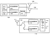
- FIG. 1 is a diagram of a first embodiment of a MIMO system according to the present invention.
- the figure shows an example in which two signals are OFDM-modulated by the same carrier wave and transmitted simultaneously, and is composed of a transmitting device 100 and a receiving device 110.
- the first signal 101 of the transmission device 100 is modulated by the first OFDM modulation circuit 103 and transmitted from the antenna 103.
- the second signal 102 is modulated by the second OFDM modulation circuit 104, delayed by a predetermined time by the delay circuit 107, and transmitted from the antenna 104.
- the receiving apparatus 110 has one antenna 111, and is alternately switched and connected to the first OFDM demodulation circuit 113 and the second OFDM demodulation circuit 114 by the switching circuit 112 within one signal period (transmission pulse period).
- the OFDM demodulation circuit 113 and the OFDM demodulation circuit 114 input the demodulated signal to the control circuit 115.
- the control circuit 115 obtains a channel response matrix between the transmission device 100 and the reception device 110 according to the MIMO technique.
- the receiving apparatus 110 separates the received signal using the channel response matrix, and outputs two outputs 116 and 117 corresponding to the first signal 101 and the second signal 102 transmitted by the transmitting apparatus 100.
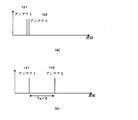
- FIG. 2 is a diagram illustrating a relationship between signals transmitted from two antennas.
- (A) of the figure shows a case where delayed transmission is not performed for any antenna, and shows that transmission 121 from antenna 1 and transmission 121 from antenna 2 are performed almost simultaneously.
- FIG. 2B shows that transmission 132 from antenna 2 is executed with a delay of [Ts / 2] from transmission 131 from antenna 1. Note that the pulse length (transmission pulse period) of this configuration is in the range of [ ⁇ Ts, Ts].
- FIG. 3 is a diagram illustrating the received signal and the timing of fractional interval sampling in the receiving apparatus.
- (A) of the figure is a case where delayed transmission is not performed for the two signals (s1, s2), and (b) the signal s1 of the antenna 1 is not delayed transmitted, and the signal s2 of the antenna 2 is [ It is a figure which shows the timing at the time of performing delayed transmission of [Ts / 2].
- the coefficient c (k) is a coefficient depending on the pulse shaping filter or the like.
- the received signal r2 (k) is obtained by multiplying r1 (k) by c (k), and the rank of the matrix of H (k) HH (k) is 1.
- the channel response matrix is as follows.
- s1 is a signal of the transmission antenna 1
- s2 is a signal of the transmission antenna 2.
- the signal received by the antenna 111 is input to the first OFDM demodulation circuit 113 by the switching circuit 112 and sampled at the central point (T1) of the pulse length.
- the signal from the antenna is input to the second OFDM demodulation circuit 114 by the switching circuit 112, and is sampled at the central time point (T2) of the period Ts.
- the OFDM demodulation circuit 113 and the OFDM demodulation circuit 114 pass the demodulated signal to the control circuit 115.
- r1 (k) is a value sampled at T1, and is the product of s1, s2, and each channel response.
- the value r2 (k) at the sampling time T2 is “0”. Therefore, the signals s1 and s2 transmitted from r1 (k) and r2 (k) influence each other, and the error rate increases.
- a MIMO system that receives a plurality of signals transmitted from a plurality of antennas by a receiving antenna that is equivalently increased by fractional interval sampling and separates the plurality of signals. Signals transmitted from some of the plurality of transmission antennas are transmitted with a predetermined delay.
- FIG. 1 shows a signal transmitted from an antenna 2 out of two antennas that transmit a signal with a pulse length (transmission pulse period) [ ⁇ Ts, Ts], as shown in FIG. Ts / 2 "is transmitted with a delay. If the size of DFT / IDFT is N, delay transmission is
- the rank of the matrix of H (k) HH (k) can be set to 2.
- Equation 7 assuming that the transmission signal is not affected by the filter and the coefficient c (k) is “0”, the channel response matrix of Equation 7 is
- the matrix of H (k) HH (k) is expressed as The rank is 1.
- cij (k) is a coefficient representing the contribution of the i-th multipath signal to the j-th sample. Also in this case, the rank of the matrix of H (k) HH (k) can be made 2 by performing delayed transmission.
- the horizontal axis represents the signal energy to noise ratio (Es / N0), and the vertical axis represents the ergodic capacity (Ergodic Capacity: bps / Hz). It shows that the channel capacity increases by delaying the transmission signal.
- FIGS. 5A and 5B are simulation results of channel capacity of the delayed transmission fraction interval sampling method according to the first embodiment of the present invention and the conventional delayed transmission diversity reception method used in Patent Document 1 and the like.
- the horizontal axis represents the signal energy to noise ratio (Es / N0), and the vertical axis represents the ergodic capacity (Ergodic Capacity: bps / Hz).
- FIG. 5A is a configuration used in the simulation
- FIG. 5B is a configuration according to the first embodiment of the present invention.
- One of the two transmission signals s1 (k) and s2 (k) s2 (k) Is delayed by [Ts / 2].
- FIG. 5-2 (a) is a configuration of the conventional system shown in the above-mentioned Patent Document 1 and the like, an antenna for adding two signals s1 (k) and s2 (k) and transmitting, and two signals s1 (k). And s2 (k) are added to each other and delayed by [Ts / 2] and [Ts], respectively, and transmitted.
- FIG. 5-2 (b) shows the result of the simulation, graph A is the result of the configuration of FIG. 5-1 (b), graph B is the result of the configuration of FIG. 5-1 (a), and graph C is the transmission signal.
- the configuration according to the first embodiment of the present invention can increase the channel capacity when no delay is performed and when compared with the conventional delayed transmission diversity reception system.
- the conventional configuration shown in FIG. 5-1 (a) transmits a plurality of identical data series from a plurality of antennas, and sets different delay amounts between different data series.
- fractional interval sampling is applied to the configuration and the number of samplings and the number of data series are the same or the number of data series is large, the diversity effect is lost for a specific data series.
- the equation corresponding to equation 10 is
- r1 (k) and r2 (k) show the response given by c (h11 (k) + h12 (k)), so that the diversity effect cannot be obtained.
- FIG. 1 The example shown in FIG. 1 is a configuration in which two signals are transmitted by two antennas, but a configuration in which three or more signals are transmitted by using three or more antennas is also possible.
- FIG. 6A shows a configuration in which the first embodiment of the present invention is applied to MIMO in which Mt signals are transmitted by Mt antennas.
- This figure shows the Mth signal, s1 (k) 201 to sMt (k) 203, modulated by OFDM modulation circuits 211 to 213 and transmitted from the transmission circuits 231 to 233, respectively, and the Kth signal (K 2 to Mt) are transmitted with a delay of [Ts (K-1) / Mt].
- FIG. 6B shows the configuration shown in FIG. 6A.
- the four signals 1 to 4 (510 to 504) of the transmission apparatus 500 are modulated by the OFDM modulation circuits 511 to 514, and then given the delays shown in FIG. Sent from 531 to 534. Since the delay amount of signal 1 (510) is zero, the output of OFDM modulation circuit 511 is transmitted from antenna 531 without passing through the delay circuit.
- the configuration including the OFDM demodulation circuit 624 corresponds to the configuration including the antenna 111, the switching circuit 112, the first OFDM demodulation circuit 113, and the second OFDM demodulation circuit 114 of the reception circuit 110 illustrated in FIG.
- the switching circuit 611 and the switching circuit 613 execute double fractional sampling with respect to the signals received by the antenna 601 and the antenna 603, and input to the OFDM demodulation circuits 621 to 624.
- the four signals demodulated by the OFDM demodulation circuits 621 to 624 are passed to the control circuit 650, and a channel response matrix between the transmission device 500 and the reception device 600 is obtained according to the MIMO technique.
- the control circuit 650 uses the channel response matrix to output four outputs corresponding to the signals 1 to 4 (510 to 504) transmitted from the transmitter 500 from the output signals of the OFDM demodulation circuits 621 to 624. Separates and outputs 651 to 654.
- the channel response matrix of the mth receive antenna in subcarrier k is
- the rank of the channel response matrix is 2 at maximum.
- the received signal is expressed as follows.
- the rank of the matrix is 4.
- the MIMO system can increase the communication capacity by setting multiple communication channels on a single carrier.
- the number of antennas corresponding to the number of communication channels must be set in the transmitter and receiver. It is necessary to install them apart to achieve diversity.
- the first embodiment of the present invention has a configuration in which one reception signal is sampled in a fractional interval to virtually increase the number of reception antennas and a transmission signal is transmitted with a time delay adapted to the fractional interval sampling. is doing.
- the receiving apparatus can virtually use one receiving antenna as a plurality of receiving antennas, and there is no need to install a plurality of antennas in a small casing such as a mobile device.
- the transmission device delays the transmission signal in a time suitable for the fractional interval sampling of the reception device, so that the channel response between the transmission device and the reception device can be separated.
- the communication distance is relatively short in indoor communication such as UWB (ultra-wide band wireless) communication
- the transmission device and the transmission / reception device can be seen, the delay amount of the signal from the antenna is small, This is applied when the channel response is expected to be Equation 4, and a predetermined delay amount is inserted in advance in the transmission signal.
- the positional relationship between the transmitter and the receiver changes, and the channel response characteristics also change. Therefore, there may be a case where a sufficient effect cannot be obtained with a configuration in which a predetermined delay amount is inserted in advance in the transmission signal.
- the second embodiment of the present invention is characterized in that it is determined whether or not a predetermined delay amount is inserted into a transmission signal in accordance with a response characteristic of a channel between the transmission device and the reception device.
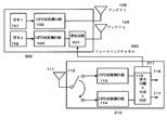
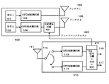
- FIG. 7 is a block diagram of the second embodiment of the present invention.
- the transmission apparatus 300 includes a delay circuit 301 that delays a transmission signal for a predetermined time in accordance with an instruction from the reception apparatus 310.
- the receiving apparatus 310 includes a determination circuit 311 that instructs the transmitting apparatus 300 to delay the transmission signal in accordance with the channel response characteristics between the transmitting apparatus 300 and the receiving apparatus 310.
- the determination circuit 311 uses the link from the reception device 310 to the transmission device 300 as the feedback channel 320 and transmits the delay instruction to the transmission device 300.
- Transmitting apparatus 300 controls delay circuit 301 in accordance with the above instruction, and transmits the output of OFDM modulation circuit 104 from antenna 2 with a predetermined delay.
- the MIMO system transmits a preamble such as a PN code before transmitting actual data.
- Receiving device 310 receives the preamble and calculates response characteristics H (K) of each channel between transmitting device 300 and receiving device 310 from the characteristics of the received signal.
- the determination circuit 311 of the receiving device 310 in the second embodiment of the present invention analyzes the channel response characteristic H (K) and separates the two actual data transmitted by the transmitting device 300 in the reception of actual data. It is determined whether sufficient response characteristics are obtained.
- a delay instruction is transmitted to the transmission apparatus side 300 via the feedback channel 320.
- the transmitter 300 receiving the instruction controls a delay circuit 301 installed between the OFDM modulator 104 and the transmitter of the antenna 2 to generate a signal 2 modulated by the OFDM modulator 104 [Ts / 2] is inserted.
- a predetermined delay amount is inserted in advance in the transmission signal.
- a portable receiving device such as a mobile phone
- the channel response characteristics also change greatly.
- H (K) of the channel measured by the receiving apparatus it is determined when the channel response characteristics are poor and a delay is necessary, and a transmission signal delay is inserted.
- no delay is performed.
- the receiving apparatus 310 determines whether or not to delay the transmission signal based on the channel response characteristic H (K), and sends an instruction to delay to the transmitting apparatus 300 via the feedback channel 320. It is the structure which transmits.
- the response characteristic H (K) of the channel is transmitted from the receiving apparatus 310 to the transmitting apparatus 300, and the transmitting apparatus 300 determines whether to delay the transmission signal.
- the transmission apparatus 300 does not need to include a means for determining whether or not a delay is necessary, and the configuration of the reception apparatus can be simplified.
- FIG. 7 shows an example in which two signals are transmitted by two antennas in the second embodiment. Three or more antennas are used by using three or more antennas as shown in FIGS. 6-1 and 6-2. It is also possible to transmit the signals simultaneously.
- the receiving apparatus 600 in FIG. 6-2 determines whether to delay each transmission signal based on the response characteristic H (K) of the channel, and transmits the transmission signal delay to the transmitting apparatus 500 via the feedback channel. Or a response characteristic H (K) of the channel is transmitted from the receiving apparatus 600 to the transmitting apparatus 500, and the transmitting apparatus 500 determines whether to delay each transmission signal.
- FIG. 8 is a block diagram of the third embodiment of the present invention.
- the receiving apparatus 410 determines the delay amount that maximizes the channel capacity from the response characteristics of the channel with the transmitting apparatus 400, and delays the transmission signal to the transmitting apparatus by the delay amount.
- control is performed so that the channel capacity represented by Equation 13 is maximized.
- N is the number of subcarriers in the OFDM modulation scheme
- ⁇ is the signal-to-noise power.
- the third embodiment searches for a delay amount that provides the best channel response characteristics between the transmission device and the reception device, and controls transmission by the transmission device based on the delay amount. Therefore, it is possible to obtain a good channel capacity in accordance with the communication environment between the transmission device and the reception device. Also, as in the second embodiment, the channel response information acquired by the transmission device is fed back to the transmission device, and the transmission device determines the optimum delay amount based on the channel response characteristics and delays the transmission signal. Configuration is also possible.
- FIG. 8 shows an example in which two signals are transmitted by two antennas in the third embodiment. Three or more antennas are used by using three or more antennas as shown in FIGS. 6-1 and 6-2. It is also possible to transmit the signals simultaneously.
- the receiving apparatus 600 in FIG. 6B determines the delay amount of each transmission signal that provides the best channel response characteristics based on the channel response characteristics H (K), and transmits the transmission apparatus 500 via the feedback channel. Or a delay instruction for each transmission signal in which the channel response characteristic H (K) is transmitted from the receiving apparatus 600 to the transmitting apparatus 500 and the channel response characteristic is the best. It becomes the structure which determines quantity.
- the present invention relates to a MIMO system, and more particularly to a MIMO system in which a receiving apparatus samples a signal received by one antenna at a fractional interval, and the number of receiving antennas is equivalently increased.
- the first embodiment of the present invention is a configuration in which a part of a transmission signal is delayed in advance by a transmission apparatus and transmitted by an optimal delay amount determined from the number of fractional sampling oversampling and the pulse length of the transmission signal. . With this configuration, it is possible to obtain good channel response characteristics with a simple configuration in a MIMO system using fractional interval sampling.
- the second embodiment is configured to determine whether or not to delay the transmission signal based on the channel response characteristic acquired by the receiving apparatus.
- the channel response characteristics between the transmitting device and the receiving device may change greatly as the receiving device moves.
- This embodiment has a configuration for determining whether or not transmission is delayed with respect to the transmission signal in accordance with the channel response characteristic acquired by the receiving apparatus. With this configuration, it is possible to obtain good channel response characteristics even with a portable receiving device.
- the third embodiment has a configuration in which a delay amount that maximizes the channel capacity is searched based on the channel response characteristic acquired by the receiving device, and a signal transmitted by the transmitting device is delayed based on the delay amount. Yes. With this configuration, even when the communication environment between the portable receiving device and the transmitting device changes greatly, it is possible to obtain optimum channel response characteristics between the two.
- the configuration of the present invention is also effective in a MIMO system using an OFDM diversity reception method using time shift sampling.
- the configuration shown in FIG. 1 to FIG. 8 transmits a different signal from each of a plurality of antennas of a transmitting apparatus, and samples the signals received by each antenna of one or a plurality of antennas provided in the receiving apparatus at fractional intervals. Then, a plurality of different signals transmitted by the transmission device are obtained by the control circuit for separation, synthesis, and determination. However, it is also possible to transmit the same signal from a plurality of antennas of the transmission device with a predetermined delay. In this case, the receiving apparatus samples the signals received by the respective antennas at fractional intervals, and the control circuit separates the signals transmitted from the plurality of antennas of the transmitting apparatus. Next, the separated signals are added to obtain the desired signal. With this configuration, it is possible to increase the energy of the transmission signal.
Landscapes
- Engineering & Computer Science (AREA)
- Signal Processing (AREA)
- Computer Networks & Wireless Communication (AREA)
- Quality & Reliability (AREA)
- Radio Transmission System (AREA)
Abstract
Description
等価的にアンテナ数を増加させる方法として、分数間隔サンプリングが提案されている。分数間隔サンプリング方式は、従来のOFDM復調に必要なサンプリング速度のG倍の速度でサンプリングすることにより、等価的にG本のアンテナによるダイバーシチを達成するものである。この構成により、MIMOシステムにおいてチャネル容量の増加が可能となる。
非特許文献4には、受信側で複数のアンテナを用いてMIMO伝送を行う場合に送信側で位相を回転させてチャネルの応答を変化させる方法が記載されている。しかしこの方法は信号分離ができなくなる状態を防ぐものであり、後述のH(k)HH(k)の行列のランクを増加させる効果はない。また、分数間隔サンプリングに対応した方式ではない。
本発明は、複数の送信アンテナから異なる情報を同一の搬送波により送信し、受信装置において上記異なる情報を分離するMIMOシステムにおいて、受信装置が分数間隔サンプリングを行うことにより受信アンテナの数を低減することを可能とするものであり、送信装置に少なくとも1つの送信信号を前記分数間隔サンプリングに適合した時間遅延させて送信する構成を備える。また、他の実施態様の受信装置はパイロット信号の復調結果に基づいて、送信装置に少なくとも1つの送信信号を所定時間遅延して送信することを指示する構成を有している。
送信装置100の第1の信号101は第1のOFDM変調回路103により変調されアンテナ103から送信される。第2の信号102は第2のOFDM変調回路104により変調され、遅延回路107により所定時間遅延されてアンテナ104から送信される。
受信装置110は1つのアンテナ111を有しており、1信号期間(送信パルス期間)内に、切替回路112により第1のOFDM復調回路113と第2のOFDM復調回路114に交互に切り替え接続することにより分数間隔サンプリングを実行する。OFDM復調回路113とOFDM復調回路114は復調した信号を制御回路115に入力する。制御回路115はMIMOの手法に従って送信装置100と受信装置110の間のチャネル応答行列を求める。受信装置110は、受信した信号を上記チャネル応答行列を用いて分離し、送信装置100が送信した第1の信号101と第2の信号102に対応する2つの出力116と117を出力する。
図2(b)はアンテナ2からの送信132が、アンテナ1からの送信131から[Ts/2]遅れて実行されることを示している。なお、本構成のパルス長(送信パルス期間)は[-Ts,Ts]の範囲とする。
図3は受信装置における受信信号と分数間隔サンプリングのタイミングを示す図である。同図の(a)は2つの信号(s1、s2)に対して遅延送信を行わない場合であり、(b)信号はアンテナ1の信号s1は遅延送信されず、アンテナ2の信号s2は[Ts/2]の遅延送信を行った場合のタイミングを示す図である。




例えば、送信信号がフィルタ等により影響されず、係数c(k)を「0」と仮定すると、チャネル応答行列は以下のようになる。


r1(k)=h11(k)s1(k)+h12(k)s2(k)
r2(k)=0
となる。
式6で表される信号を、図1の受信装置110により受信し処理するタイミングが図3(a)に示される。同図のs1は送信アンテナ1の信号であり、s2は送信アンテナ2の信号で
ある。
アンテナ111により受信された信号は切替回路112により第1OFDM復調回路113に入力され、パルス長の中央時点(T1)でサンプリングされる。次に、アンテナからの信号は切替回路112により第2OFDM復調回路114に入力され、期間Tsの中央時点(T2)でサンプリングされる。OFDM復調回路113とOFDM復調回路114は復調した信号を制御回路115に渡す。
r1(k)は、T1でサンプリングされた値であり、s1とs2と各チャネル応答の積となる。これに対して、サンプリング時点T2の値r2(k)は「0」となる。従って、r1(k)とr2(k)から送信された信号s1とs2が互いに影響して誤り率が増加する。
図1は、信号をパルス長(送信パルス期間)[-Ts,Ts]で送信さする2つのアンテナの内、アンテナ2から送信される信号を、図2(b)に示されるように、「Ts/2」遅延させ
て送信するものである。
DFT/IDFTのサイズをNとすると、遅延送信することは、式4を



r1(k)=h11(k)s1(k)
r2(k)=h12(k)s2(k)
となり、ランクは2となる。これは、図3(b)において、サンプリング点T1では遅延されていないアンテナ1からの信号s1を受信し、サンプリング点T2では「Ts/2」遅延されているアンテナ2からの信号s2を受信することを意味している。


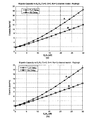
図4は、2本のアンテナから送信された2つの信号(Tx=2)を、1本のアンテナにより受信(Rx=1)し、分数間隔サンプリングにより処理するシステムの通信容量を、送信信号の一方を[Ts/2]遅延する場合(グラフA)と、遅延を行わない場合(グラフB)でチャネル容量をシミュレートした結果である。図4(a)は2倍の分数間隔サンプリング(G=2)であり、図4(b)は4倍の分数間隔サンプリング(G=4)である。なお、横軸は、信号エネルギー対雑音比(Es/N0)であり、縦軸は、エルゴード容量(Ergodic Capacity : bps/Hz)である。
送信信号を遅延することによりチャネル容量が増加することを示している。
図5-1は当該シミュレーションで用いた構成であり、(b)は本発明の第1実施態様に係る構成であり、2つの送信信号s1(k)とs2(k)の一方s2(k)を[Ts/2]遅延するものである。また、(a)は上記の特許文献1等に示される従来方式の構成であり、2つの信号s1(k)とs2(k)を加算して送信するアンテナと、2つの信号s1(k)とs2(k)を各々[Ts/2]と[Ts]遅延して加算し送信するアンテナからなるものである。
図5-2(a)はシミュレートのパラメータであり、当該シミュレーションは図5-1(a)の構成において2倍の分数間隔サンプリング(G=2)で行ったものである。図5-2(b)はシミュレーションの結果であり、グラフAは図5-1(b)の構成による結果、グラフBは図5-1(a)の構成による結果、グラフCは送信信号に遅延を行わない場合の結果である。同図に示されるように、本発明の第1実施態様に係る構成は、遅延を行わない場合、及び従来の遅延送信ダイバーシチ受信方式に比較してチャネル容量の増加が可能となる。
図5-1(a)に示される従来の構成は、複数のアンテナから複数かつ同一のデータ系列
を送信するものであり、異なるデータ系列間では異なる遅延量を設定するものである。当該構成に分数間隔サンプリングを適用し、サンプリング数とデータ系列数が同一か、データ系列数が多い場合には、特定のデータ系列に対してダイバーシチ効果がなくなる。つまり式10に対応する式は

同図は、Mtの信号、s1(k)201~sMt(k)203を各々OFDM変調回路211~213により変調し、送信回路231~233より送信するMIMOシステムにおい、第K番の信号(Kは2~Mt)を[Ts(K-1)/Mt]遅延して送信するものである。受信装置は、受信信号を少なくともMt倍の分数間隔サンプリング(G=Mt)により受信し、チャネル応答行列を判別する。
送信装置500の4つの信号1~信号4(510~504)はOFDM変調回路511~514により変調された後、各々対応する遅延回路522~424により図6-1に示される遅延が与えられアンテナ531~534から送信される。なお、信号1(510)の遅延量はゼロであるため、OFDM変調回路511の出力は遅延回路を介すことなくアンテナ531から送信される。







本発明の第1の実施態様では、1つの受信信号を分数間隔サンプリングすることにより、受信アンテナを仮想的に増加させると共に、送信信号を分数間隔サンプリングに適合した時間遅延して送信する構成を有している。
上記構成により、受信装置は1本の受信アンテナを仮想的に複数の受信アンテナとすることが可能となり、移動機等の小さな筐体内に複数のアンテナを設置する必要がなくなる。また、送信装置は送信信号を受信装置の分数間隔サンプリングに適合した時間遅延することにより、送信装置と受信装置間のチャネル応答を各信号の分離が可能な状態とするものである。
本発明の第2実施態様は、送信装置と受信装置の間のチャネルの応答特性に応じて、所定の遅延量を送信信号に挿入するか否かを決定することを特徴とするものである。
本発明の第2の実施態様における受信装置310の判定回路311は、上記のチャネル応答特性H(K)を分析し、実データの受信において、送信装置300が送信した2つの実データを分離するのに充分な応答特性が得られたか否かを判定する。
チャネル応答が式4、或いは式10に該当する場合、フィードバックチャネル320を介して遅延指示を送信装置側300に送信する。当該指示を受信した送信装置側300はOFDM変調回路104とアンテナ2の送信装置との間に設置されている遅延回路301を制御して、OFDM変調回路104により変調された信号2に[Ts/2]の遅延を挿入する。
第2の態様は受信装置で測定されチャネルの応答特性H(K)に基づいて、送信信号を遅延するか否かを決定するものである。当該実施態様の構成により、チャネルの応答特性が悪く、遅延が必要な場合を判定し送信信号遅延を挿入する。また、良好なチャネルの応答特性が得られ遅延の挿入が不要な場合に、遅延を行わない。従って、遅延が不要であるにもかかわらず、更に遅延を挿入してチャネルの応答特性を悪化させることがなく、受信状況が大きく変化する携帯型の受信装置であっても良好な受信を維持することが可能となる。
図7に示される形態は、受信装置310がチャネルの応答特性H(K)に基づいて、送信信号を遅延するか否かを決定し、遅延する指示をフィードバックチャネル320を介して送信装置300に送信する構成である。しかし、受信装置310から送信装置300にチャネルの応答特性H(K)を送信し、送信装置300が送信信号を遅延するか否かを決定する構成も可能である。当該構成により、送信装置300は遅延の要否を決定する手段を備える必要がなく、受信装置の構成の簡素化が可能となる。
別し、送信装置に送信信号を上記遅延量により遅延することを指示する判定回路411を有している。判定回路411は受信装置から送信装置400へのリンクをフィードバックチャネル420として使用し、前記の遅延の指示を送信装置400送信する。

受信装置410から遅延の挿入指示と挿入する遅延量の情報を受信した送信装置400は、可変遅延回路401を制御し、OFDM変調回路104の出力信号を指示され時間遅延しアンテナ2から送信する。
また、第2の実施態様と同様、送信装置が取得したチャネルの応答の情報を送信装置にフィードバックし、送信装置が上記チャネル応答特性に基づいて最適な遅延量を決定し、送信信号を遅延する構成も可能である。
第2の実施態様は、受信装置が取得したチャネル応答特性に基づいて送信信号を遅延するか否かを判定する構成としたものである。携帯電話等の移動可能な受信装置では、送信装置と受信装置間のチャネル応答特性は受信装置の移動に伴い大きく変化する場合がある。当実施態様では、受信装置により取得されたチャネル応答特性に応じて送信信号に遅延して送信するが否かを決定する構成を有している。この構成により、携帯可能な受信装置であっても良好なチャネル応答特性を得ることが可能となる。
第3の実施態様は、受信装置が取得したチャネル応答特性に基づいてチャネル容量が最大となる遅延量を探査し、当該遅延量に基づいて送信装置が送信する信号を遅延する構成を有している。当該構成により、携帯可能な受信装置と送信装置の間の通信環境が大きく変化しても、両者間の最適なチャネル応答特性を得ることが可能となる。
また、本発明の構成は時間シフトサンプリングを用いたOFDMダイバーシチ受信方式を利用したMIMOシステムにおいても有効である。
Claims (6)
- 複数のアンテナから同一の搬送波により複数系列のデータを送信する送信装置と、1本又は複数のアンテナにより前記複数系列のデータを受信する受信装置からなるマルチキャリア通信システムであって、
前記送信装置は、
前記複数系列の一部の系列のデータを所定の時間遅延して前記複数のアンテナから送信する送信手段を有し、
前記受信装置は、
前記1本又は複数のアンテナの各アンテナにより受信した信号を分数間隔サンプリングする手段と、
前記分数間隔サンプリングより得られた信号に基づいて前記複数系列のデータを復調する手段を有することを特徴とするマルチキャリア通信システム。 - 請求項1記載のマルチキャリア通信システムであって、
送信パルス期間を[-Ts,Ts]、送信信号の多重数をMtとすると、
K(2<=K<=Mt)番目の送信信号に対する前記遅延時間はTs (K-1)/Mtであることを特徴とするマルチキャリア通信システム。 - 請求項1又は請求項2記載のマルチキャリア通信システムであって、
前記受信装置は、受信したマルチキャリア信号のチャネルの応答特性の良否を判定する手段と、
前記判定手段の判定結果に基づいて前記送信装置にデータを前記所定の時間遅延して送信することを指示する手段を有することを特徴とするマルチキャリア通信システム。 - 請求項1又は請求項2記載のマルチキャリア通信システムであって、
前記受信装置は、
受信したマルチキャリア信号のチャネルの応答特性のデータを前記送信装置に送信する手段を有し、
前記送信装置は、
前記受信装置が送信した前記チャネルの応答特性のデータに基づいてチャネルの応答特性の良否を判定する手段と、
前記判定手段の判定結果に基づいてデータを前記所定の時間遅延して送信することを特徴とするマルチキャリア通信システム。 - 請求項1記載のマルチキャリア通信システムであって、
前記受信装置は、受信したマルチキャリア信号のチャネルの応答特性から送信信号に必要な遅延量を判別する手段と、
前記判別した遅延量に基づいて前記送信装置にデータを遅延して送信することを指示する手段を有することを特徴とするマルチキャリア通信システム。 - 請求項1記載のマルチキャリア通信システムであって
前記受信装置は、
受信したマルチキャリア信号のチャネルの応答特性のデータを前記送信装置に送信する手段を有し、
前記送信装置は、
前記受信装置が送信した前記チャネルの応答特性のデータから送信信号に必要な遅延量を判別する手段と、
前記判別した遅延量に基づいてデータの送信を遅延する手段を有することを特徴とするマルチキャリア通信システム。
Priority Applications (3)
| Application Number | Priority Date | Filing Date | Title |
|---|---|---|---|
| US12/996,707 US8451927B2 (en) | 2008-07-04 | 2009-06-02 | Multicarrier communication system |
| JP2010518884A JP5305305B2 (ja) | 2008-07-04 | 2009-06-02 | マルチキャリア通信システム |
| IL209173A IL209173A0 (en) | 2008-07-04 | 2010-11-07 | Multicarrier communication system |
Applications Claiming Priority (2)
| Application Number | Priority Date | Filing Date | Title |
|---|---|---|---|
| JP2008176119 | 2008-07-04 | ||
| JP2008-176119 | 2008-07-04 |
Publications (1)
| Publication Number | Publication Date |
|---|---|
| WO2010001528A1 true WO2010001528A1 (ja) | 2010-01-07 |
Family
ID=41465637
Family Applications (1)
| Application Number | Title | Priority Date | Filing Date |
|---|---|---|---|
| PCT/JP2009/002448 Ceased WO2010001528A1 (ja) | 2008-07-04 | 2009-06-02 | マルチキャリア通信システム |
Country Status (5)
| Country | Link |
|---|---|
| US (1) | US8451927B2 (ja) |
| JP (1) | JP5305305B2 (ja) |
| KR (1) | KR20110031165A (ja) |
| IL (1) | IL209173A0 (ja) |
| WO (1) | WO2010001528A1 (ja) |
Cited By (1)
| Publication number | Priority date | Publication date | Assignee | Title |
|---|---|---|---|---|
| JP2012095060A (ja) * | 2010-10-27 | 2012-05-17 | Nec Corp | 無線送信装置、無線受信装置、クロック同期方法および無線通信システム |
Families Citing this family (2)
| Publication number | Priority date | Publication date | Assignee | Title |
|---|---|---|---|---|
| CN114157329B (zh) * | 2020-09-08 | 2022-10-21 | 中国移动通信有限公司研究院 | 一种信号接收方法、设备及存储介质 |
| JP7613876B2 (ja) * | 2020-10-15 | 2025-01-15 | トヨタ自動車株式会社 | 受信側装置及び無線通信方法 |
Citations (2)
| Publication number | Priority date | Publication date | Assignee | Title |
|---|---|---|---|---|
| WO2007052768A1 (ja) * | 2005-11-04 | 2007-05-10 | Matsushita Electric Industrial Co., Ltd. | 無線送信装置、無線受信装置、無線通信方法及び無線通信システム |
| JP2008079217A (ja) * | 2006-09-25 | 2008-04-03 | Keio Gijuku | Ofdm通信装置 |
Family Cites Families (5)
| Publication number | Priority date | Publication date | Assignee | Title |
|---|---|---|---|---|
| KR100312836B1 (ko) * | 1997-06-03 | 2001-12-28 | 다치카와 게이지 | 어댑티브어레이송수신기 |
| US7042926B2 (en) * | 2001-11-21 | 2006-05-09 | Intel Corporation | Low complexity multiuser detector |
| JP3677492B2 (ja) | 2002-07-31 | 2005-08-03 | 松下電器産業株式会社 | マルチキャリア送信装置およびマルチキャリア送信方法 |
| US7436903B2 (en) * | 2004-09-29 | 2008-10-14 | Intel Corporation | Multicarrier transmitter and method for transmitting multiple data streams with cyclic delay diversity |
| US20070041457A1 (en) * | 2005-08-22 | 2007-02-22 | Tamer Kadous | Method and apparatus for providing antenna diversity in a wireless communication system |
-
2009
- 2009-06-02 JP JP2010518884A patent/JP5305305B2/ja not_active Expired - Fee Related
- 2009-06-02 US US12/996,707 patent/US8451927B2/en not_active Expired - Fee Related
- 2009-06-02 WO PCT/JP2009/002448 patent/WO2010001528A1/ja not_active Ceased
- 2009-06-02 KR KR1020107029691A patent/KR20110031165A/ko not_active Withdrawn
-
2010
- 2010-11-07 IL IL209173A patent/IL209173A0/en unknown
Patent Citations (2)
| Publication number | Priority date | Publication date | Assignee | Title |
|---|---|---|---|---|
| WO2007052768A1 (ja) * | 2005-11-04 | 2007-05-10 | Matsushita Electric Industrial Co., Ltd. | 無線送信装置、無線受信装置、無線通信方法及び無線通信システム |
| JP2008079217A (ja) * | 2006-09-25 | 2008-04-03 | Keio Gijuku | Ofdm通信装置 |
Non-Patent Citations (4)
| Title |
|---|
| "Communications, Computers and Signal Processing, 2007. PacRim 2007. IEEE Pacific Rim Conference on, 2007.08.22", article TSUBASA TAMURA ET AL.: "Fractional Sampling OFDM/OQAM-IOTA on Multipath Channel with Long Delay Spread", pages: 510 - 513 * |
| "Vehicular Technology Conference, 2008. VTC 2008-Fall. IEEE 68th, 2008.09.21", article HUI LU ET AL.: "SVD-Based Frequency Domain Equalizer for MIMO-CDMA Systems Using Virtual Antennas", pages: 1 - 5 * |
| "Vehicular Technology Conference, 2008. VTC 2008-Fall. IEEE 68th, 2008.09.21", article YUKITOSHI SANADA ET AL.: "Multipath Diversity through Time Shifted Sampling for Spatially Correlated OFDM-Antenna Array Systems", pages: 1 - 5 * |
| QIXING WANG ET AL.: "Deliberately Designed Asynchronous Transmission Scheme for MIMO Systems", SIGNAL PROCESSING LETTERS, IEEE, December 2007 (2007-12-01), pages 920 - 923 * |
Cited By (1)
| Publication number | Priority date | Publication date | Assignee | Title |
|---|---|---|---|---|
| JP2012095060A (ja) * | 2010-10-27 | 2012-05-17 | Nec Corp | 無線送信装置、無線受信装置、クロック同期方法および無線通信システム |
Also Published As
| Publication number | Publication date |
|---|---|
| IL209173A0 (en) | 2011-01-31 |
| US8451927B2 (en) | 2013-05-28 |
| JP5305305B2 (ja) | 2013-10-02 |
| JPWO2010001528A1 (ja) | 2011-12-15 |
| US20110096818A1 (en) | 2011-04-28 |
| KR20110031165A (ko) | 2011-03-24 |
Similar Documents
| Publication | Publication Date | Title |
|---|---|---|
| US9001774B2 (en) | System and method for channel estimation in a delay diversity wireless communication system | |
| EP2153543B1 (en) | Short range booster and methods for boosting with multiple antennas | |
| CN105684323B (zh) | 用于在无线通信系统中发送信号的方法和设备 | |
| CN106576036B (zh) | 发送用于估计模拟波束的训练符号的方法和设备 | |
| KR101120316B1 (ko) | 트랜시버 및 송신 방법 | |
| CN107836089A (zh) | 混合波束成形多天线无线系统 | |
| EP2157717B1 (en) | Method and system and device for CQI estimation disturbance cancellation | |
| EP2148483B1 (en) | OFDM system with subcarrier group phase rotation | |
| WO2021074000A1 (en) | Spatial multiplexing with single transmitter on wideband channels | |
| WO2008151534A1 (fr) | Système à multiples antennes et procédé de transmission de données | |
| EP2044717B1 (en) | Multicarrier transmission with time diversity and/or frequency diversity | |
| US9106289B2 (en) | Antenna device and method for precoding data in a multiple-input multiple-output system | |
| CN105519029A (zh) | Ofdm通信系统及信号收发方法与装置 | |
| JP5305305B2 (ja) | マルチキャリア通信システム | |
| EP3806523A1 (en) | Method and apparatus for sending signal, method and apparatus for reporting channel state information, and storage medium | |
| TW200513052A (en) | Method and system of path gain estimation in a WCDMA system | |
| CN115987739A (zh) | 一种基于双时间尺度的通信感知一体化信号处理方法 | |
| KR101685305B1 (ko) | Mimo-ofdm 시스템 및 그것을 이용한 하이브리드 협력 통신 방법 | |
| KR101084696B1 (ko) | 공간 다중화 초광대역 통신을 위한 송수신 시스템 | |
| KR20130005491A (ko) | 시공간 부호화 직교 주파수분할 다중화 기반 저복잡도 다중 안테나 릴레이 전송 기법 | |
| Fu et al. | Study on the Application of MIMO System | |
| NISHIMURA | Path Diversity Schemes in OFDM Transmitter and Receiver |
Legal Events
| Date | Code | Title | Description |
|---|---|---|---|
| 121 | Ep: the epo has been informed by wipo that ep was designated in this application |
Ref document number: 09773106 Country of ref document: EP Kind code of ref document: A1 |
|
| WWE | Wipo information: entry into national phase |
Ref document number: 2010518884 Country of ref document: JP |
|
| WWE | Wipo information: entry into national phase |
Ref document number: 12996707 Country of ref document: US |
|
| ENP | Entry into the national phase |
Ref document number: 20107029691 Country of ref document: KR Kind code of ref document: A |
|
| NENP | Non-entry into the national phase |
Ref country code: DE |
|
| 122 | Ep: pct application non-entry in european phase |
Ref document number: 09773106 Country of ref document: EP Kind code of ref document: A1 |