WO2009153841A1 - Mass analyzer - Google Patents
Mass analyzer Download PDFInfo
- Publication number
- WO2009153841A1 WO2009153841A1 PCT/JP2008/001602 JP2008001602W WO2009153841A1 WO 2009153841 A1 WO2009153841 A1 WO 2009153841A1 JP 2008001602 W JP2008001602 W JP 2008001602W WO 2009153841 A1 WO2009153841 A1 WO 2009153841A1
- Authority
- WO
- WIPO (PCT)
- Prior art keywords
- ion
- ions
- voltage
- ion trap
- end cap
- Prior art date
Links
- 238000005040 ion trap Methods 0.000 claims abstract description 72
- 150000002500 ions Chemical class 0.000 claims description 134
- 239000007789 gas Substances 0.000 claims description 17
- 238000004458 analytical method Methods 0.000 claims description 15
- 238000001816 cooling Methods 0.000 claims description 15
- 239000000112 cooling gas Substances 0.000 claims description 8
- 238000000034 method Methods 0.000 abstract description 13
- 238000003776 cleavage reaction Methods 0.000 abstract description 8
- 230000007017 scission Effects 0.000 abstract description 8
- 238000002955 isolation Methods 0.000 abstract description 7
- 238000004140 cleaning Methods 0.000 abstract 1
- 238000001269 time-of-flight mass spectrometry Methods 0.000 abstract 1
- 238000001360 collision-induced dissociation Methods 0.000 description 8
- 230000005684 electric field Effects 0.000 description 6
- 239000002243 precursor Substances 0.000 description 6
- 238000000752 ionisation method Methods 0.000 description 5
- XKRFYHLGVUSROY-UHFFFAOYSA-N Argon Chemical compound [Ar] XKRFYHLGVUSROY-UHFFFAOYSA-N 0.000 description 4
- 238000000605 extraction Methods 0.000 description 3
- IJGRMHOSHXDMSA-UHFFFAOYSA-N Atomic nitrogen Chemical compound N#N IJGRMHOSHXDMSA-UHFFFAOYSA-N 0.000 description 2
- 230000001133 acceleration Effects 0.000 description 2
- 229910052786 argon Inorganic materials 0.000 description 2
- 238000010586 diagram Methods 0.000 description 2
- 230000005284 excitation Effects 0.000 description 2
- 239000001307 helium Substances 0.000 description 2
- 229910052734 helium Inorganic materials 0.000 description 2
- SWQJXJOGLNCZEY-UHFFFAOYSA-N helium atom Chemical compound [He] SWQJXJOGLNCZEY-UHFFFAOYSA-N 0.000 description 2
- 239000011261 inert gas Substances 0.000 description 2
- 239000007788 liquid Substances 0.000 description 2
- 238000004949 mass spectrometry Methods 0.000 description 2
- 238000012986 modification Methods 0.000 description 2
- 230000004048 modification Effects 0.000 description 2
- 238000007792 addition Methods 0.000 description 1
- 239000003990 capacitor Substances 0.000 description 1
- 238000000451 chemical ionisation Methods 0.000 description 1
- 239000011248 coating agent Substances 0.000 description 1
- 238000000576 coating method Methods 0.000 description 1
- 230000008878 coupling Effects 0.000 description 1
- 238000010168 coupling process Methods 0.000 description 1
- 238000005859 coupling reaction Methods 0.000 description 1
- 238000001514 detection method Methods 0.000 description 1
- 238000000132 electrospray ionisation Methods 0.000 description 1
- 238000001819 mass spectrum Methods 0.000 description 1
- 238000000816 matrix-assisted laser desorption--ionisation Methods 0.000 description 1
- 229910052757 nitrogen Inorganic materials 0.000 description 1
- 239000007787 solid Substances 0.000 description 1
- 238000001228 spectrum Methods 0.000 description 1
Images

Classifications
-
- H—ELECTRICITY
- H01—ELECTRIC ELEMENTS
- H01J—ELECTRIC DISCHARGE TUBES OR DISCHARGE LAMPS
- H01J49/00—Particle spectrometers or separator tubes
- H01J49/004—Combinations of spectrometers, tandem spectrometers, e.g. MS/MS, MSn
-
- H—ELECTRICITY
- H01—ELECTRIC ELEMENTS
- H01J—ELECTRIC DISCHARGE TUBES OR DISCHARGE LAMPS
- H01J49/00—Particle spectrometers or separator tubes
- H01J49/26—Mass spectrometers or separator tubes
- H01J49/34—Dynamic spectrometers
- H01J49/36—Radio frequency spectrometers, e.g. Bennett-type spectrometers, Redhead-type spectrometers
-
- H—ELECTRICITY
- H01—ELECTRIC ELEMENTS
- H01J—ELECTRIC DISCHARGE TUBES OR DISCHARGE LAMPS
- H01J49/00—Particle spectrometers or separator tubes
- H01J49/02—Details
- H01J49/04—Arrangements for introducing or extracting samples to be analysed, e.g. vacuum locks; Arrangements for external adjustment of electron- or ion-optical components
- H01J49/0468—Arrangements for introducing or extracting samples to be analysed, e.g. vacuum locks; Arrangements for external adjustment of electron- or ion-optical components with means for heating or cooling the sample
- H01J49/0481—Arrangements for introducing or extracting samples to be analysed, e.g. vacuum locks; Arrangements for external adjustment of electron- or ion-optical components with means for heating or cooling the sample with means for collisional cooling
-
- H—ELECTRICITY
- H01—ELECTRIC ELEMENTS
- H01J—ELECTRIC DISCHARGE TUBES OR DISCHARGE LAMPS
- H01J49/00—Particle spectrometers or separator tubes
- H01J49/26—Mass spectrometers or separator tubes
- H01J49/34—Dynamic spectrometers
- H01J49/40—Time-of-flight spectrometers
-
- H—ELECTRICITY
- H01—ELECTRIC ELEMENTS
- H01J—ELECTRIC DISCHARGE TUBES OR DISCHARGE LAMPS
- H01J49/00—Particle spectrometers or separator tubes
- H01J49/26—Mass spectrometers or separator tubes
- H01J49/34—Dynamic spectrometers
- H01J49/42—Stability-of-path spectrometers, e.g. monopole, quadrupole, multipole, farvitrons
- H01J49/4205—Device types
- H01J49/424—Three-dimensional ion traps, i.e. comprising end-cap and ring electrodes
-
- H—ELECTRICITY
- H01—ELECTRIC ELEMENTS
- H01J—ELECTRIC DISCHARGE TUBES OR DISCHARGE LAMPS
- H01J49/00—Particle spectrometers or separator tubes
- H01J49/26—Mass spectrometers or separator tubes
- H01J49/34—Dynamic spectrometers
- H01J49/42—Stability-of-path spectrometers, e.g. monopole, quadrupole, multipole, farvitrons
- H01J49/426—Methods for controlling ions
- H01J49/427—Ejection and selection methods
Definitions
- the present invention provides a mass spectrometer comprising: an ion trap that captures and accumulates ions by an electric field; and a time-of-flight mass analyzer that separates and detects ions emitted from the ion trap according to m / z About.
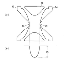
- ion trap As an ion trap, a linear type configuration in which a plurality of rod electrodes are arranged in parallel is also known. However, as shown in FIG. 3A, the annular ring electrode 31 and the ring electrode 31 are arranged opposite to each other. A three-dimensional quadrupole configuration including a pair of end cap electrodes 32 and 34 is widely used.
- the ion trap refers to this three-dimensional quadrupole ion trap.
- the end cap electrodes 32 and 34 are set to, for example, the ground potential, and a high-frequency high voltage with variable amplitude is applied to the ring electrode 31 to form a quadrupole electric field in a space surrounded by the electrodes.
- the ions are confined by the action of the electric field.
- a coil is connected to the ring electrode, the inductance of the coil, the capacitance between the ring electrode and two end cap electrodes, and the ring electrode
- An LC resonant circuit is formed with the capacitances of all other circuit elements connected to.
- a high frequency drive source (RF excitation circuit) for driving the LC resonance circuit is connected directly or through a transformer coupling.
- the amplitude is amplified using a high Q value, and a high-frequency high-frequency voltage can be applied to the ring electrode with a small drive voltage (see, for example, Patent Document 1).
- D z (V / 8) ⁇ q z (1)
- q z 8 ⁇ z ⁇ e ⁇ V / m ⁇ (r 0 2 + 2 ⁇ z 0 2 ) ⁇ ⁇ 2 (2)
- e is the elementary charge
- z is the number of charges of the ions
- V and ⁇ are the amplitude and angular frequency of the high frequency high voltage applied to the ring electrode 31 respectively
- m is the mass of the ions
- r 0 is the ring electrode 31
- the inscribed radius, z 0, is the shortest distance from the center point of the ion trap 3 to the end cap electrodes 32, 34.
- q z is one of the parameters indicating the stability condition of the solution of the Mathieu equation of motion.
- ions are accumulated in the ion trap 3 and then a high-frequency voltage with a small amplitude is applied between the end cap electrodes 32 and 34 while the ions are trapped in the ion trap 3.
- ions having a specific m / z corresponding to the frequency or included in the m / z range are resonance-excited and excluded from the ion trap 3, that is, ions are selected (isolated).
- the ions remaining in the ion trap are excited to collide with the CID gas. Promotes ion cleavage.
- product ions having smaller m / z are trapped and accumulated in the ion trap 3.
- an inert gas such as helium or argon is introduced into the ion trap 3, and the ions are allowed to collide with the gas molecules to reduce the kinetic energy of the ions.
- a process called cooling is performed.
- the spatial distribution state of ions in the ion trap 3 depends on the amplitude of the voltage applied to the ring electrode 31. This is because, as can be seen from the equation (1), the pseudopotential potential D z becomes shallower as the amplitude V of the high frequency high voltage applied to the ring electrode 31 becomes smaller, and ions tend to exist in a spread state. .
- the reflectron type TOF corrects the variation of the position of the ion starting point when the ions are folded back. However, if the initial distribution of the ion starting point becomes too large, it is out of the correctable range, resulting in a mass deviation. Realize.
- the pseudo-potential potential D z expressed by the equation (1) as much as possible in the cooling process before ion emission.
- the pseudo-potential potential D z is proportional to the square of the amplitude V of the high-frequency high voltage applied to the ring electrode 31, the pseudo-potential potential D z increases as the amplitude V is increased.
- increasing the amplitude V increases the qz value. From theory based on the stability conditions of the solution of the above-mentioned Mathieu equation, the trapping ions within the ion trap 3 is known to need to the q z value to 0.908 or less.
- the amplitude V may be increased in proportion to the square.
- q z value is taken as double the frequency ⁇ , it is necessary to quadruple the amplitude V.
- more high q z value is increasing its mass selectivity in making isolation of ions must be fairly large amplitude V and a high m / z of the target ions isolation.
- JP 2004-214077 A Junichi Taniguchi and Eizo Kawato, “Development of High Performance Liquid Chromatograph / Ion Trap Time-of-Flight Mass Spectrometer”, Analytical Chemistry, Analytical Chemistry of Japan, Analytical Chemistry, January 5, 2008, Vol. 57, No. 1 , P. 1-13
- the present invention has been made to solve the above problems, and its purpose is to deepen the pseudopotential potential in the ion trap during cooling without affecting ion selection. It is an object of the present invention to provide an ion trap time-of-flight mass spectrometer capable of improving the spatial convergence of ions immediately before emission of ions, improving the mass resolution of analysis by TOF, and reducing the mass deviation.
- the present invention comprises an ion trap composed of a ring electrode and a pair of end cap electrodes, and a time-of-flight mass analyzer that performs mass analysis of ions emitted from the ion trap.
- a high-frequency high voltage is applied to the ring electrode in the cooling stroke, thereby forming a pseudopotential potential for trapping ions.
- the end cap electrode is formed in the cooling stroke.
- a high frequency high voltage is applied to the capacitor to form a pseudopotential potential.
- a high frequency high voltage is applied to the ring electrode as in the past. Conventionally, a high frequency (alternating current) voltage has been applied between the end cap electrodes.
- this has a specific m / z or m / z for ion isolation or CID.
- the purpose was to excite ions included in the z range, and the amplitude was only about 10 [V] at most.
- the mass spectrometer according to the present invention is configured such that a high frequency high voltage having an amplitude of 100 [V] or more can be selectively applied to the end cap electrode.
- the frequency of the high frequency high voltage applied to the end cap electrode can be determined regardless of the frequency of the high frequency high voltage applied to the ring electrode during the isolation operation.
- the frequency of the high frequency high voltage applied to the end cap electrode is set to be higher than the frequency of the high frequency high voltage applied to the ring electrode.
- the pseudo-potential potential in order to increase the pseudo-potential potential while maintaining the q z value shown in equation (2), along with a higher frequency of the high frequency high voltage whose amplitude is also necessary to increase.
- a large pseudopotential potential can be formed in the ion trap during the cooling process, and ions can be efficiently collected in the center of the ion trap.
- mass spectrometer of the present invention for example, ion extraction is performed while maintaining mass selectivity at the time of isolating a specific ion in order to leave a precursor ion for MS n analysis in the ion trap as usual.
- the pseudopotential potential in the previous cooling stroke can be increased to improve ion convergence.
- variations in the initial position of ions when ions are introduced into the time-of-flight mass analyzer are reduced, so that mass resolution of mass analysis can be improved and mass deviation can be reduced.
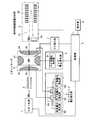
- FIG. 1 is an overall configuration diagram of an IT-TOFMS according to an embodiment of the present invention.
- the flowchart which shows an example of the procedure of the mass spectrometry by IT-TOFMS of a present Example.
- the figure which shows schematic structure and pseudo-potential potential shape of a general three-dimensional quadrupole ion trap.
- FIG. 1 is a configuration diagram of the main part of the IT-TOFMS of this embodiment.
- an ionization unit 1 an ion guide 2, an ion trap 3, and a time-of-flight mass analyzer (TOFMS) 4 are disposed inside a vacuum chamber (not shown).
- a vacuum chamber not shown.
- the sample is a solid sample, such as an atmospheric pressure ionization method such as an electrospray ionization method when the sample is a liquid sample, and an electron ionization method or a chemical ionization method when the sample is a gas sample.
- the sample components can be ionized using various ionization methods such as laser ionization.
- the ion trap 3 is a three-dimensional four-piece structure comprising a single annular ring electrode 31 and a pair of end cap electrodes 32 and 34 provided so as to sandwich the ring electrode 31. This is a quadrupole ion trap.
- An ion introduction port 33 is bored at substantially the center of the inlet end cap electrode 32, and an ion emission port 35 is bored at substantially the center of the exit end cap electrode 34 so as to be substantially in line with the ion introduction port 33. .
- the TOFMS 4 has a flight space 41 having an reflectron electrode 42 and an ion detector 43, and ions are folded back by an electric field formed by a voltage applied to the reflectron electrode 42 from a DC voltage generator (not shown). It reaches the detector 43 and is detected.
- the ring electrode 31 is connected to the ring voltage generator 5, and the end cap electrodes 32 and 34 are connected to the end cap voltage generator 6.
- the ring voltage generator 5 includes a high frequency (RF) high voltage generator 51 using, for example, an LC resonance circuit disclosed in Patent Document 1.
- the end cap voltage generation unit 6 includes a high frequency high voltage generation unit 63 having the same configuration as the high frequency high voltage generation unit 51 included in the ring voltage generation unit 5 in addition to the DC voltage generation unit 61 and the high frequency low voltage generation unit 62. These voltages are switched by the voltage switching unit 64 and applied to the end cap electrodes 32 and 34.
- the amplitude of the high-frequency voltage generated by the high-frequency high-voltage generator 63 is 100 [V] or more and reaches the kV order, whereas the amplitude of the high-frequency voltage generated by the high-frequency low-voltage generator 62 is much higher than this. It is about 10 [V] at most.
- the DC voltage generator 61 and the high frequency low voltage generator 62 are also provided in the conventional IT-TOFMS, but the high frequency high voltage generator 63 is not provided in the conventional IT-TOFMS.
- the cooling gas or CID gas is selectively introduced into the inside of the ion trap 3 from the gas introduction part 7 including a valve and the like.
- a stable gas that does not ionize or cleave even when it collides with ions to be measured for example, an inert gas such as helium, argon, or nitrogen is used.
- the operations of the ionization unit 1, the TOFMS 4, the ring voltage generation unit 5, the end cap voltage generation unit 6, the gas introduction unit 7 and the like are controlled by a control unit 8 mainly composed of a CPU.
- the control unit 8 is provided with an operation unit 9 for setting analysis conditions and the like.
- FIG. 2 is a flowchart of the analysis procedure using the IT-TOFMS of this embodiment.
- FIG. 2A shows a case where no cleavage operation is performed
- FIG. 2B shows a case where a single cleavage operation is performed, that is, a case where MS / MS analysis is performed.
- the basic operation of the mass spectrometer of the present embodiment will be described according to these flowcharts.
- the ionization unit 1 ionizes component molecules or atoms of the target sample by a predetermined ionization method (step S1).
- the generated ions are transported by the ion guide 2, introduced into the ion trap 3 through the ion introduction port 33, and captured therein (step S ⁇ b> 2).
- the DC voltage generator 61 and the end cap electrodes 32 and 34 are connected by the voltage switching unit 64, and the incident end cap 32 is sent from the ion guide 2.
- a direct current voltage is applied so as to attract the incoming ions, and a direct current voltage is applied to the emission-side end cap electrode 34 such that ions incident on the ion trap 3 are pushed back.
- the ionization unit 1 When the ionization unit 1 generates ions in a pulse shape like MALDI, the ion is generated by applying a high frequency high voltage to the ring electrode 31 immediately after the incoming ion packet is taken into the ion trap 3. To capture.
- a potential is applied to the end of the ion guide 2 by coating a part of the rod electrode of the ion guide 2 with a resistor. Can be formed, and ions can be temporarily accumulated in the dent, compressed in a short time, and introduced into the ion trap 3 (see, for example, p. 3-5 of Non-Patent Document 1).
- the high frequency high voltage applied to the ring electrode 31 has, for example, a frequency of 500 [kHz] and an amplitude of 100 [V] to several [kV]. This amplitude is appropriately determined according to the m / z range of ions to be captured.
- a cooling gas is introduced into the ion trap 3 from the gas introduction unit 7, and as described later, this is formed by applying a high frequency high voltage to the end cap electrodes 32 and 34.
- the ions are cooled while being captured by the quadrupole electric field (step S5).
- an initial acceleration energy is applied to the ions by applying a DC high voltage between the end cap electrodes 32 and 34, and the ions are ejected through the ion ejection port 35 and introduced into the TOFMS 4 (step S6). .
- ions accelerated by the same acceleration voltage have a larger velocity as m / z is smaller, they fly earlier and reach the ion detector 43 to be detected (step S7).
- the detection signal from the ion detector 43 is recorded with the passage of time starting from the time when ions are emitted from the ion trap 3, a time-of-flight spectrum is obtained showing the relationship between the flight time and the ion intensity. Since the flight time corresponds to the ion m / z, the mass spectrum is created by converting the flight time to m / z.
- steps S3 and S4 are executed between steps S2 and S5. That is, after various ions having various m / z are captured in the ion trap 3 in step S2, the high-frequency and low-voltage generation unit 62 and the end cap electrodes 32 and 34 are connected by the voltage switching unit 64 to form precursor ions.
- a small-amplitude high-frequency voltage having a frequency component having a notch at a frequency corresponding to m / z of ions to be left is applied between the end cap electrodes 32 and 34.
- ions having m / z other than m / z corresponding to the notch frequency are excited and greatly oscillated and discharged from the ion inlet 33 and ion outlet 35 or on the inner surfaces of the end cap electrodes 32 and 34. It disappears when it collides.
- ions having a specific m / z are selectively left in the ion trap 3 (step S3).
- a high frequency high voltage is subsequently applied to the ring electrode 31.
- CID gas is introduced into the ion trap 3 by the gas introduction unit 7, and a small-amplitude high-frequency voltage having a frequency corresponding to m / z of the precursor ion is applied between the end cap electrodes 32 and 34.
- the precursor ion given kinetic energy is excited and collides with the CID gas, causing cleavage to generate product ions (step S4). Since the product ions generated in this way have a smaller m / z than the original precursor ions, the amplitude of the high frequency high voltage applied to the ring electrode 31 is determined so that such low m / z ions can also be captured.
- the trapped product ions are cooled in step S5 and then emitted from the ion trap 3 for mass analysis.
- steps S3 and S4 in FIG. 2B may be repeated a plurality of times.
- step S5 In the cooling process of step S5, conventionally, ions are trapped by applying a high frequency high voltage to the ring electrode 31, as in the case of ion trapping in step S2 or ion sorting in step S3.
- a high frequency high voltage is applied to the end cap electrodes 32 and 34 instead of the ring electrode 31, thereby generating a trapping quadrupole electric field in the ion trap 3. Yes.
- the voltage application to the ring electrode 31 is generally stopped, and the ring electrode 31 is set to the ground potential.
- a high frequency high voltage having the same phase is applied to both end cap electrodes 32, 34.
- the frequency of the high frequency high voltage applied to the end cap electrodes 32 and 34 can be determined as appropriate, but is higher than the frequency of the high frequency high voltage applied to the ring electrode 31, for example, 1 [MHz] which is twice as high. can do.
- the amplitude may be about 400 [V].
- [MHz] it is necessary to increase the amplitude to about 1.6 [kV] which is four times.
- pseudo-potential potential as evidenced by (1), appears strongly influenced raising the amplitude than q z value, twice the frequency, when four times the amplitude, pseudo-potential potential 4 times greater Clearly
Abstract
Description
Dz=(V/8)・qz …(1)
qz=8・z・e・V/m・(r0 2+2・z0 2)・Ω2 …(2)
ここでeは電気素量、zはイオンの電荷数、V及びΩはそれそれリング電極31に印加される高周波高電圧の振幅及び角周波数、mはイオンの質量、r0はリング電極31の内接半径、z0はイオントラップ3の中心点からエンドキャップ電極32、34までの最短距離である。よく知られているように、qzはマチウ(Mathieu)運動方程式の解の安定条件を示すパラメータの1つである。 As described above, when a high frequency high voltage is applied to the
D z = (V / 8) · q z (1)
q z = 8 · z · e · V / m · (r 0 2 + 2 · z 0 2 ) · Ω 2 (2)
Here, e is the elementary charge, z is the number of charges of the ions, V and Ω are the amplitude and angular frequency of the high frequency high voltage applied to the
a)エンドキャップ電極に高周波高電圧と直流電圧とを選択的に印加する電圧印加手段と、
b)イオントラップ内にクーリングガスを導入するガス導入手段と、
c)イオントラップ内に分析対象イオンを捕捉した状態で、前記ガス導入手段によりクーリングガスをイオントラップ内に導入するとともに前記電圧印加手段により前記エンドキャップ電極に高周波高電圧を印加することでイオンのクーリングを実行し、その後に、前記電圧印加手段により前記エンドキャップ電極に直流電圧を印加しイオンに運動エネルギーを付与してイオントラップから出射させる制御手段と、
を備えることを特徴としている。 In order to solve the above-mentioned problems, the present invention comprises an ion trap composed of a ring electrode and a pair of end cap electrodes, and a time-of-flight mass analyzer that performs mass analysis of ions emitted from the ion trap. In the mass spectrometer to
a) voltage applying means for selectively applying a high-frequency high voltage and a DC voltage to the end cap electrode;
b) gas introduction means for introducing cooling gas into the ion trap;
c) In a state where ions to be analyzed are trapped in the ion trap, a cooling gas is introduced into the ion trap by the gas introducing means, and a high frequency high voltage is applied to the end cap electrode by the voltage applying means. Control means for performing cooling, and thereafter applying a DC voltage to the end cap electrode by the voltage application means to impart kinetic energy to the ions and eject the ions from the ion trap;
It is characterized by having.
2…イオンガイド
3…イオントラップ
31…リング電極
32、34…エンドキャップ電極
33…イオン導入口
35…イオン出射口
4…飛行時間型質量分析器(TOFMS)
41…飛行空間
42…リフレクトロン電極
43…イオン検出器
5…リング電圧発生部
51…高周波高電圧発生部
6…エンドキャップ電圧発生部
61…直流電圧発生部
62…高周波低電圧発生部
63…高周波高電圧発生部
64…電圧切替部
7…ガス導入部
8…制御部
9…操作部 DESCRIPTION OF SYMBOLS 1 ...
DESCRIPTION OF
Claims (2)
- リング電極及び一対のエンドキャップ電極からなるイオントラップと、該イオントラップから出射されたイオンを質量分析する飛行時間型質量分析器と、を具備する質量分析装置において、
a)エンドキャップ電極に高周波高電圧と直流電圧とを選択的に印加する電圧印加手段と、
b)イオントラップ内にクーリングガスを導入するガス導入手段と、
c)イオントラップ内に分析対象イオンを捕捉した状態で、前記ガス導入手段によりクーリングガスをイオントラップ内に導入するとともに前記電圧印加手段により前記エンドキャップ電極に高周波高電圧を印加することでイオンのクーリングを実行し、その後に、前記電圧印加手段により前記エンドキャップ電極に直流電圧を印加しイオンに運動エネルギーを付与してイオントラップから出射させる制御手段と、
を備えることを特徴とする質量分析装置。 In a mass spectrometer comprising: an ion trap composed of a ring electrode and a pair of end cap electrodes; and a time-of-flight mass analyzer that performs mass analysis of ions emitted from the ion trap.
a) voltage applying means for selectively applying a high-frequency high voltage and a DC voltage to the end cap electrode;
b) gas introduction means for introducing cooling gas into the ion trap;
c) In a state where ions to be analyzed are trapped in the ion trap, a cooling gas is introduced into the ion trap by the gas introducing means and a high frequency high voltage is applied to the end cap electrode by the voltage applying means. Control means for performing cooling, and thereafter applying a DC voltage to the end cap electrode by the voltage application means to impart kinetic energy to the ions and eject the ions from the ion trap;
A mass spectrometer comprising: - 請求項1に記載の質量分析装置であって、
リング電極にイオン捕捉用の高周波高電圧を印加するリング電圧印加手段をさらに備え、
クーリング実行時に前記電圧印加手段によりエンドキャップ電極に印加する高周波高電圧の周波数を、前記リング電圧印加手段によるイオン捕捉用の高周波高電圧の周波数よりも高い周波数に設定しておくことを特徴とする質量分析装置。 The mass spectrometer according to claim 1,
A ring voltage applying means for applying a high frequency high voltage for ion trapping to the ring electrode;
The frequency of the high frequency high voltage applied to the end cap electrode by the voltage application means during cooling is set to be higher than the frequency of the high frequency high voltage for ion trapping by the ring voltage application means. Mass spectrometer.
Priority Applications (5)
| Application Number | Priority Date | Filing Date | Title |
|---|---|---|---|
| US12/999,957 US8754368B2 (en) | 2008-06-20 | 2008-06-20 | Mass spectrometer |
| CN200880129936.7A CN102067275B (en) | 2008-06-20 | 2008-06-20 | Mass analyzer |
| EP08764185.8A EP2309531B1 (en) | 2008-06-20 | 2008-06-20 | Mass spectrometer |
| PCT/JP2008/001602 WO2009153841A1 (en) | 2008-06-20 | 2008-06-20 | Mass analyzer |
| JP2010517557A JP5158196B2 (en) | 2008-06-20 | 2008-06-20 | Mass spectrometer |
Applications Claiming Priority (1)
| Application Number | Priority Date | Filing Date | Title |
|---|---|---|---|
| PCT/JP2008/001602 WO2009153841A1 (en) | 2008-06-20 | 2008-06-20 | Mass analyzer |
Publications (1)
| Publication Number | Publication Date |
|---|---|
| WO2009153841A1 true WO2009153841A1 (en) | 2009-12-23 |
Family
ID=41433772
Family Applications (1)
| Application Number | Title | Priority Date | Filing Date |
|---|---|---|---|
| PCT/JP2008/001602 WO2009153841A1 (en) | 2008-06-20 | 2008-06-20 | Mass analyzer |
Country Status (5)
| Country | Link |
|---|---|
| US (1) | US8754368B2 (en) |
| EP (1) | EP2309531B1 (en) |
| JP (1) | JP5158196B2 (en) |
| CN (1) | CN102067275B (en) |
| WO (1) | WO2009153841A1 (en) |
Cited By (1)
| Publication number | Priority date | Publication date | Assignee | Title |
|---|---|---|---|---|
| JP2012123959A (en) * | 2010-12-07 | 2012-06-28 | Shimadzu Corp | Ion trap time-of-flight mass analyzer |
Families Citing this family (15)
| Publication number | Priority date | Publication date | Assignee | Title |
|---|---|---|---|---|
| GB0817433D0 (en) * | 2008-09-23 | 2008-10-29 | Thermo Fisher Scient Bremen | Ion trap for cooling ions |
| WO2012137806A1 (en) * | 2011-04-04 | 2012-10-11 | 株式会社島津製作所 | Mass spectrometry device and mass spectrometry method |
| US9218948B2 (en) * | 2012-03-22 | 2015-12-22 | Shimadzu Corporation | Mass spectrometer |
| DE102012013038B4 (en) | 2012-06-29 | 2014-06-26 | Bruker Daltonik Gmbh | Eject an ion cloud from 3D RF ion traps |
| US9818593B2 (en) | 2012-09-13 | 2017-11-14 | University Of Maine System Board Of Trustees | Radio-frequency ionization of chemicals |
| GB201409074D0 (en) * | 2014-05-21 | 2014-07-02 | Thermo Fisher Scient Bremen | Ion ejection from a quadrupole ion trap |
| CN104658850B (en) * | 2015-02-16 | 2016-05-11 | 中国科学院地质与地球物理研究所 | Experimental rig and the method for designing thereof in a kind of novel electron bombarding ion source |
| EP3379560A4 (en) * | 2015-09-29 | 2019-08-21 | Shimadzu Corporation | Liquid sample introduction system for ion source and alanysis device |
| CN110383418B (en) * | 2017-03-07 | 2021-06-25 | 株式会社岛津制作所 | Ion trap arrangement |
| JP6835210B2 (en) * | 2017-04-10 | 2021-02-24 | 株式会社島津製作所 | Ion analyzer and ion dissociation method |
| CN109300766B (en) * | 2018-08-09 | 2024-03-29 | 金华职业技术学院 | Molecular photoreaction testing method |
| CN108987241B (en) * | 2018-08-09 | 2024-01-30 | 金华职业技术学院 | Molecular light reaction testing device |
| CN110277302B (en) * | 2019-06-28 | 2021-06-15 | 清华大学深圳研究生院 | Ion trap and method for improving ion binding efficiency |
| JP7215589B2 (en) * | 2019-09-27 | 2023-01-31 | 株式会社島津製作所 | Ion trap mass spectrometer, mass spectrometry method and control program |
| JP7409260B2 (en) * | 2020-08-19 | 2024-01-09 | 株式会社島津製作所 | Mass spectrometry method and mass spectrometer |
Citations (3)
| Publication number | Priority date | Publication date | Assignee | Title |
|---|---|---|---|---|
| JP2004206933A (en) * | 2002-12-24 | 2004-07-22 | Hitachi High-Technologies Corp | Mass spectrometer and mass spectrometric method |
| JP2004214077A (en) | 2003-01-07 | 2004-07-29 | Shimadzu Corp | Mass spectrometer and mass spectrometry |
| JP2008091199A (en) * | 2006-10-02 | 2008-04-17 | Shimadzu Corp | Mass spectrometer |
Family Cites Families (4)
| Publication number | Priority date | Publication date | Assignee | Title |
|---|---|---|---|---|
| JP3480409B2 (en) * | 2000-01-31 | 2003-12-22 | 株式会社島津製作所 | Ion trap type mass spectrometer |
| GB0031342D0 (en) * | 2000-12-21 | 2001-02-07 | Shimadzu Res Lab Europe Ltd | Method and apparatus for ejecting ions from a quadrupole ion trap |
| US6838665B2 (en) * | 2002-09-26 | 2005-01-04 | Hitachi High-Technologies Corporation | Ion trap type mass spectrometer |
| GB0416288D0 (en) * | 2004-07-21 | 2004-08-25 | Micromass Ltd | Mass spectrometer |
-
2008
- 2008-06-20 WO PCT/JP2008/001602 patent/WO2009153841A1/en active Application Filing
- 2008-06-20 EP EP08764185.8A patent/EP2309531B1/en not_active Not-in-force
- 2008-06-20 US US12/999,957 patent/US8754368B2/en not_active Expired - Fee Related
- 2008-06-20 CN CN200880129936.7A patent/CN102067275B/en not_active Expired - Fee Related
- 2008-06-20 JP JP2010517557A patent/JP5158196B2/en active Active
Patent Citations (3)
| Publication number | Priority date | Publication date | Assignee | Title |
|---|---|---|---|---|
| JP2004206933A (en) * | 2002-12-24 | 2004-07-22 | Hitachi High-Technologies Corp | Mass spectrometer and mass spectrometric method |
| JP2004214077A (en) | 2003-01-07 | 2004-07-29 | Shimadzu Corp | Mass spectrometer and mass spectrometry |
| JP2008091199A (en) * | 2006-10-02 | 2008-04-17 | Shimadzu Corp | Mass spectrometer |
Non-Patent Citations (2)
| Title |
|---|
| JUNICHI TANIGUCHI; EIZOH KAWATOH: "Development of High-performance Liquid Chromatograph/IT-TOF Mass Spectrometer", BUNSEKI KAGAKU, vol. 57, no. 1, 5 January 2008 (2008-01-05), pages 1 - 13 |
| See also references of EP2309531A4 |
Cited By (1)
| Publication number | Priority date | Publication date | Assignee | Title |
|---|---|---|---|---|
| JP2012123959A (en) * | 2010-12-07 | 2012-06-28 | Shimadzu Corp | Ion trap time-of-flight mass analyzer |
Also Published As
| Publication number | Publication date |
|---|---|
| CN102067275B (en) | 2014-03-12 |
| CN102067275A (en) | 2011-05-18 |
| EP2309531A4 (en) | 2013-11-20 |
| JP5158196B2 (en) | 2013-03-06 |
| US20110095180A1 (en) | 2011-04-28 |
| EP2309531A1 (en) | 2011-04-13 |
| US8754368B2 (en) | 2014-06-17 |
| EP2309531B1 (en) | 2017-08-09 |
| JPWO2009153841A1 (en) | 2011-11-17 |
Similar Documents
| Publication | Publication Date | Title |
|---|---|---|
| JP5158196B2 (en) | Mass spectrometer | |
| JP4745982B2 (en) | Mass spectrometry method | |
| JP5081436B2 (en) | Mass spectrometer and mass spectrometry method | |
| JP5623428B2 (en) | Mass spectrometer for MS / MS / MS | |
| JP4918846B2 (en) | Mass spectrometer and mass spectrometry method | |
| JP4690641B2 (en) | Mass spectrometer | |
| JP4636943B2 (en) | Mass spectrometer | |
| US7759641B2 (en) | Ion trap mass spectrometer | |
| JP4463978B2 (en) | Method and apparatus for selective collision-induced dissociation of ions in a quadrupole ion guide | |
| US20110248157A1 (en) | Mass spectrometer and mass spectrometry method | |
| CA2955665A1 (en) | Method for tandem mass spectrometry analysis in ion trap mass analyzer | |
| JP2005183022A (en) | Mass spectroscope | |
| JP5481115B2 (en) | Mass spectrometer and mass spectrometry method | |
| JP5449701B2 (en) | Mass spectrometer | |
| EP1051731A1 (en) | Method of analyzing ions in an apparatus including a time of flight mass spectrometer and a linear ion trap | |
| US9576779B2 (en) | System and method for quantitation in mass spectrometry | |
| US20220384173A1 (en) | Methods and Systems of Fourier Transform Mass Spectrometry | |
| JP5206605B2 (en) | Ion trap mass spectrometer | |
| JP2009146913A (en) | Mass spectrometer |
Legal Events
| Date | Code | Title | Description |
|---|---|---|---|
| WWE | Wipo information: entry into national phase |
Ref document number: 200880129936.7 Country of ref document: CN |
|
| 121 | Ep: the epo has been informed by wipo that ep was designated in this application |
Ref document number: 08764185 Country of ref document: EP Kind code of ref document: A1 |
|
| WWE | Wipo information: entry into national phase |
Ref document number: 2010517557 Country of ref document: JP |
|
| NENP | Non-entry into the national phase |
Ref country code: DE |
|
| WWE | Wipo information: entry into national phase |
Ref document number: 12999957 Country of ref document: US |
|
| REEP | Request for entry into the european phase |
Ref document number: 2008764185 Country of ref document: EP |
|
| WWE | Wipo information: entry into national phase |
Ref document number: 2008764185 Country of ref document: EP |