JP5158196B2 - Mass spectrometer - Google Patents
Mass spectrometer Download PDFInfo
- Publication number
- JP5158196B2 JP5158196B2 JP2010517557A JP2010517557A JP5158196B2 JP 5158196 B2 JP5158196 B2 JP 5158196B2 JP 2010517557 A JP2010517557 A JP 2010517557A JP 2010517557 A JP2010517557 A JP 2010517557A JP 5158196 B2 JP5158196 B2 JP 5158196B2
- Authority
- JP
- Japan
- Prior art keywords
- voltage
- ions
- end cap
- ion trap
- ion
- Prior art date
- Legal status (The legal status is an assumption and is not a legal conclusion. Google has not performed a legal analysis and makes no representation as to the accuracy of the status listed.)
- Active
Links
- 150000002500 ions Chemical class 0.000 claims description 137
- 238000005040 ion trap Methods 0.000 claims description 71
- 239000007789 gas Substances 0.000 claims description 17
- 238000004458 analytical method Methods 0.000 claims description 15
- 238000001816 cooling Methods 0.000 claims description 15
- 239000000112 cooling gas Substances 0.000 claims description 8
- 239000012491 analyte Substances 0.000 claims description 2
- 238000000034 method Methods 0.000 description 12
- 238000001360 collision-induced dissociation Methods 0.000 description 8
- 238000003776 cleavage reaction Methods 0.000 description 7
- 230000007017 scission Effects 0.000 description 7
- 230000005684 electric field Effects 0.000 description 6
- 239000002243 precursor Substances 0.000 description 6
- 238000000752 ionisation method Methods 0.000 description 5
- 238000002955 isolation Methods 0.000 description 5
- XKRFYHLGVUSROY-UHFFFAOYSA-N Argon Chemical compound [Ar] XKRFYHLGVUSROY-UHFFFAOYSA-N 0.000 description 4
- IJGRMHOSHXDMSA-UHFFFAOYSA-N Atomic nitrogen Chemical compound N#N IJGRMHOSHXDMSA-UHFFFAOYSA-N 0.000 description 2
- 230000001133 acceleration Effects 0.000 description 2
- 229910052786 argon Inorganic materials 0.000 description 2
- 238000010586 diagram Methods 0.000 description 2
- 230000005284 excitation Effects 0.000 description 2
- 238000000605 extraction Methods 0.000 description 2
- 239000001307 helium Substances 0.000 description 2
- 229910052734 helium Inorganic materials 0.000 description 2
- SWQJXJOGLNCZEY-UHFFFAOYSA-N helium atom Chemical compound [He] SWQJXJOGLNCZEY-UHFFFAOYSA-N 0.000 description 2
- 239000011261 inert gas Substances 0.000 description 2
- 239000007788 liquid Substances 0.000 description 2
- 238000004949 mass spectrometry Methods 0.000 description 2
- 238000012986 modification Methods 0.000 description 2
- 230000004048 modification Effects 0.000 description 2
- 238000007792 addition Methods 0.000 description 1
- 239000003990 capacitor Substances 0.000 description 1
- 238000000451 chemical ionisation Methods 0.000 description 1
- 239000011248 coating agent Substances 0.000 description 1
- 238000000576 coating method Methods 0.000 description 1
- 230000008878 coupling Effects 0.000 description 1
- 238000010168 coupling process Methods 0.000 description 1
- 238000005859 coupling reaction Methods 0.000 description 1
- 238000001514 detection method Methods 0.000 description 1
- 238000000132 electrospray ionisation Methods 0.000 description 1
- 238000001819 mass spectrum Methods 0.000 description 1
- 238000000816 matrix-assisted laser desorption--ionisation Methods 0.000 description 1
- 229910052757 nitrogen Inorganic materials 0.000 description 1
- 239000007787 solid Substances 0.000 description 1
- 238000001228 spectrum Methods 0.000 description 1
Images

Classifications
-
- H—ELECTRICITY
- H01—ELECTRIC ELEMENTS
- H01J—ELECTRIC DISCHARGE TUBES OR DISCHARGE LAMPS
- H01J49/00—Particle spectrometers or separator tubes
- H01J49/004—Combinations of spectrometers, tandem spectrometers, e.g. MS/MS, MSn
-
- H—ELECTRICITY
- H01—ELECTRIC ELEMENTS
- H01J—ELECTRIC DISCHARGE TUBES OR DISCHARGE LAMPS
- H01J49/00—Particle spectrometers or separator tubes
- H01J49/26—Mass spectrometers or separator tubes
- H01J49/34—Dynamic spectrometers
- H01J49/36—Radio frequency spectrometers, e.g. Bennett-type spectrometers, Redhead-type spectrometers
-
- H—ELECTRICITY
- H01—ELECTRIC ELEMENTS
- H01J—ELECTRIC DISCHARGE TUBES OR DISCHARGE LAMPS
- H01J49/00—Particle spectrometers or separator tubes
- H01J49/02—Details
- H01J49/04—Arrangements for introducing or extracting samples to be analysed, e.g. vacuum locks; Arrangements for external adjustment of electron- or ion-optical components
- H01J49/0468—Arrangements for introducing or extracting samples to be analysed, e.g. vacuum locks; Arrangements for external adjustment of electron- or ion-optical components with means for heating or cooling the sample
- H01J49/0481—Arrangements for introducing or extracting samples to be analysed, e.g. vacuum locks; Arrangements for external adjustment of electron- or ion-optical components with means for heating or cooling the sample with means for collisional cooling
-
- H—ELECTRICITY
- H01—ELECTRIC ELEMENTS
- H01J—ELECTRIC DISCHARGE TUBES OR DISCHARGE LAMPS
- H01J49/00—Particle spectrometers or separator tubes
- H01J49/26—Mass spectrometers or separator tubes
- H01J49/34—Dynamic spectrometers
- H01J49/40—Time-of-flight spectrometers
-
- H—ELECTRICITY
- H01—ELECTRIC ELEMENTS
- H01J—ELECTRIC DISCHARGE TUBES OR DISCHARGE LAMPS
- H01J49/00—Particle spectrometers or separator tubes
- H01J49/26—Mass spectrometers or separator tubes
- H01J49/34—Dynamic spectrometers
- H01J49/42—Stability-of-path spectrometers, e.g. monopole, quadrupole, multipole, farvitrons
- H01J49/4205—Device types
- H01J49/424—Three-dimensional ion traps, i.e. comprising end-cap and ring electrodes
-
- H—ELECTRICITY
- H01—ELECTRIC ELEMENTS
- H01J—ELECTRIC DISCHARGE TUBES OR DISCHARGE LAMPS
- H01J49/00—Particle spectrometers or separator tubes
- H01J49/26—Mass spectrometers or separator tubes
- H01J49/34—Dynamic spectrometers
- H01J49/42—Stability-of-path spectrometers, e.g. monopole, quadrupole, multipole, farvitrons
- H01J49/426—Methods for controlling ions
- H01J49/427—Ejection and selection methods
Description
本発明は、電場によりイオンを捕捉して蓄積するイオントラップと、該イオントラップから出射されたイオンをm/zに応じて分離して検出する飛行時間型質量分析器と、を備える質量分析装置に関する。 The present invention provides a mass spectrometer comprising: an ion trap that captures and accumulates ions by an electric field; and a time-of-flight mass analyzer that separates and detects ions emitted from the ion trap according to m / z About.
質量分析装置の一種として、イオン源において生成された各種イオンをイオントラップ(IT)に一旦蓄積し、その後に、それらイオンを一斉にイオントラップから出射して飛行時間型質量分析器(TOFMS)に導入する、イオントラップ飛行時間型質量分析装置(IT−TOFMS)が知られている。この種の質量分析装置では、各種イオンをイオントラップに蓄積した後に、特定のm/zをもつ又は特定のm/z範囲に含まれるイオンのみをイオントラップ内に選択的に残し、その残したイオンをプリカーサイオンとして衝突誘起解離(CID)などの手法により開裂させ、開裂により生成されたプロダクトイオンをイオントラップから出射して質量分析することも可能である。 As a kind of mass spectrometer, various ions generated in the ion source are temporarily stored in the ion trap (IT), and then the ions are emitted from the ion trap all at once to the time-of-flight mass analyzer (TOFMS). An ion trap time-of-flight mass spectrometer (IT-TOFMS) to be introduced is known. In this type of mass spectrometer, after various ions are accumulated in the ion trap, only ions having a specific m / z or included in a specific m / z range are selectively left in the ion trap. It is also possible to cleave ions as precursor ions by a technique such as collision-induced dissociation (CID), and to extract the product ions generated by the cleavage from the ion trap for mass analysis.
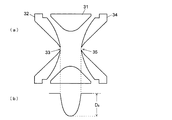
イオントラップとしては、複数のロッド電極を平行に配置したリニア型の構成も知られているが、図3(a)に示すように、円環状のリング電極31とリング電極31を挟んで対向配置された一対のエンドキャップ電極32、34とからなる3次元四重極型の構成が広く利用されている。以下、イオントラップとはこの3次元四重極型イオントラップを指すものとする。 As an ion trap, a linear type configuration in which a plurality of rod electrodes are arranged in parallel is also known. However, as shown in FIG. 3A, the
イオントラップ3では、基本的に、エンドキャップ電極32、34を例えば接地電位とし、振幅可変の高周波高電圧をリング電極31に印加することにより、それら電極で囲まれる空間に四重極電場を形成し、その電場の作用によってイオンを閉じ込める。リング電極に高周波高電圧を印加するための構成の一例としては、リング電極にコイルを接続し、そのコイルのインダクタンスと、リング電極と2つのエンドキャップ電極との間の静電容量、及びリング電極に接続された他の全ての回路要素の静電容量とでLC共振回路を形成する。このLC共振回路に、これを駆動する高周波駆動源(RF励振回路)を直接又は変圧器結合を通じて接続する。この構成では、高いQ値を利用して振幅を増幅し、小さな駆動電圧で以て、リング電極に大振幅の高周波電圧を印加することができる(例えば特許文献1など参照)。 In the
上述のようにリング電極31に高周波高電圧を印加した場合、イオントラップ3内には図3(b)に示すような形状の擬電位ポテンシャルが形成されることが知られている(非特許文献1参照)。イオンは擬電位ポテンシャルが落ち込んだポテンシャル井戸の中で振動しつつ捕捉される。理論的には、ポテンシャル井戸の深さDzは(1)、(2)式で近似される。
Dz=(V/8)・qz …(1)
qz=8・z・e・V/m・(r0 2+2・z0 2)・Ω2 …(2)
ここでeは電気素量、zはイオンの電荷数、V及びΩはそれそれリング電極31に印加される高周波高電圧の振幅及び角周波数、mはイオンの質量、r0はリング電極31の内接半径、z0はイオントラップ3の中心点からエンドキャップ電極32、34までの最短距離である。よく知られているように、qzはマチウ(Mathieu)運動方程式の解の安定条件を示すパラメータの1つである。As described above, when a high frequency high voltage is applied to the
D z = (V / 8) · q z (1)
q z = 8 · z · e · V / m · (r 0 2 + 2 · z 0 2 ) · Ω 2 (2)
Here, e is the elementary charge, z is the number of charges of the ions, V and Ω are the amplitude and angular frequency of the high frequency high voltage applied to the
MS/MS又はMSn分析を行う場合には、イオンをイオントラップ3内に蓄積した後、イオントラップ3内にイオンを捕捉しつつエンドキャップ電極32、34間に小振幅の高周波電圧を印加することで、その周波数に応じた特定のm/zを有する又はm/z範囲に含まれるイオンを共鳴励振させてイオントラップ3内から除外する、つまり、イオンの選別(アイソレーション)を行う。引き続いて、イオントラップ内にCIDガスを導入するとともにエンドキャップ電極32、34間に小振幅の高周波電圧を印加することで、イオントラップ内に残したイオンを励振させてCIDガスと衝突させ、そのイオンの開裂を促進する。これによって、より小さなm/zを持つプロダクトイオンをイオントラップ3内に捕捉・蓄積する。When performing MS / MS or MS n analysis, ions are accumulated in the
上述のようにして目的イオンをイオントラップ3に捕捉した後に、エンドキャップ電極32、34間に直流高電圧を印加することでイオンに運動エネルギーを付与し、イオンをイオントラップ3内から出射させてTOFへと送り込み、質量分析を実行する。このようにイオンをイオントラップ3から出射する際に、イオンはイオントラップ3内の中心部にできるだけ集まった状態であることが望ましい。何故なら、イオン出射時のイオンの空間的分布の拡がりは質量誤差の一因となるからである。そこで、一般に、イオンをイオントラップ3から出射する前に、イオントラップ3内にヘリウム、アルゴンなどの不活性ガスを導入し、そのガス分子にイオンを衝突させることによってイオンの運動エネルギーを減少させる、クーリングと呼ばれる行程が実行される。 After capturing the target ions in the
従来、クーリングを行う際には、イオン捕捉時と同様に、リング電極31に高周波高電圧を印加し、エンドキャップ電極32、34を接地電位とする。このとき、イオントラップ3内でのイオンの空間分布状態は、リング電極31への印加電圧の振幅に依存する。何故なら、(1)式で分かるように、リング電極31へ印加される高周波高電圧の振幅Vが小さいほど擬電位ポテンシャルDzは浅くなり、イオンが拡がった状態で存在し易くなるためである。一般にリフレクトロン型TOFでは、イオンを折り返す際にイオン出発点の位置のばらつきが補正されるが、イオン出発点の初期的な分布が大きくなりすぎると補正可能な範囲を外れ、質量ずれとなって顕在化する。Conventionally, when cooling is performed, a high frequency high voltage is applied to the
したがって、IT−TOFMSで質量分解能を向上させたり質量ずれを軽減したりするには、イオン出射前のクーリング行程において、(1)式で表される擬電位ポテンシャルDzをできるだけ大きくすることが望ましい。擬電位ポテンシャルDzはリング電極31に印加される高周波高電圧の振幅Vの二乗に比例するから、振幅Vを大きくすれば擬電位ポテンシャルDzは大きくなる。ところが、(2)式から分かるように、振幅Vを大きくするとq z値も大きくなる。上述したマチウ方程式の解の安定条件に基づく理論から、イオントラップ3内でイオンを捕捉するにはqz値を0.908以下にする必要があることが知られている。単に振幅Vを大きくすると、特に小さな質量mに対するqz値が0.908を超えてしまうおそれがある。つまり、クーリング行程でイオンの収束性を増すために擬電位ポテンシャルDzを大きくしようとすると、捕捉可能な最低質量(LMC=Low Mass Cutoff)が上がり、低m/z側のイオンを捕捉できなくなるおそれがある。 Therefore, in order to improve the mass resolution or reduce the mass deviation by IT-TOFMS, the pseudopotential potential D expressed by the equation (1) in the cooling process before the ion emission.zIs as large as possible. Pseudopotential potential DzIs proportional to the square of the amplitude V of the high-frequency high voltage applied to the
そこで、LMCを低く維持するためにqz値を保ったままで擬電位ポテンシャルDzを大きくするには、リング電極31へ印加する高周波電圧の振幅Vのみを大きくするのではなく、周波数Ωを大きくしてその二乗に比例して振幅Vも大きくすればよい。一方、(2)式から明らかなように、周波数Ωを2倍としたときに同じqz値を維持するには、振幅Vを4倍にする必要がある。イオンのアイソレーションを行う際にその質量選択性を高めるにはqz値が高いほうが好ましく、アイソレーションする対象のイオンのm/zが高いと振幅Vをかなり大きくしなければならない。例えば、r0=10[mm]、z0=7[mm]、周波数500[kHz]の条件の下でqz=0.81の動作点でm/z3000のイオンをアイソレーションするには、振幅Vは6.2[kV]ですむが、周波数を2倍の1[MHz]とすると振幅Vを4倍の24[kV]まで上げる必要がある。このようにリング電極31への印加電圧を上げることは、電極間での放電、或いは、LC共振回路の駆動能力の限界などの問題から、実際上不可能である。Therefore, in order to increase the pseudo-potential potential D z while maintaining the q z value to maintain a low LMC, rather than increasing only the amplitude V of the radio-frequency voltage applied to the
即ち、イオンをアイソレーションする際の質量選択性を良好に保つためにはリング電極31に印加する高周波高電圧の周波数と振幅とを共に上げることは望ましくない。一方、IT−TOFMSで質量分解能の向上や質量ずれの軽減を図るためには、イオントラップからのイオン出射前のクーリング行程においてイオンの収束性を高める必要があり、擬電位ポテンシャルを大きくしたいという要求がある。 That is, it is not desirable to increase both the frequency and the amplitude of the high frequency high voltage applied to the
本発明は上記課題を解決するために成されたものであり、その目的とするところは、イオン選別に影響を与えることなく、クーリングの際のイオントラップ内の擬電位ポテンシャルを深くすることで、イオンを出射する直前のイオンの空間的な収束性を高め、TOFによる分析の質量分解能の向上や質量ずれの軽減を図ることができるイオントラップ飛行時間型質量分析装置を提供することにある。 The present invention has been made to solve the above problems, and its purpose is to deepen the pseudopotential potential in the ion trap during cooling without affecting ion selection. It is an object of the present invention to provide an ion trap time-of-flight mass spectrometer capable of improving the spatial convergence of ions immediately before emission of ions, improving the mass resolution of analysis by TOF, and reducing the mass deviation.
上記課題を解決するために成された本発明は、リング電極及び一対のエンドキャップ電極からなるイオントラップと、該イオントラップから出射されたイオンを質量分析する飛行時間型質量分析器と、を具備する質量分析装置において、
a)リング電極に振幅が100[V]以上であるイオン捕捉用の高周波高電圧を印加するリング電圧印加手段と、
b)エンドキャップ電極に振幅が100[V]以上である高周波高電圧と直流電圧とを選択的に印加するエンドキャップ電圧印加手段と、
c)イオントラップ内にクーリングガスを導入するガス導入手段と、
d)前記リング電圧印加手段からリング電極に高周波高電圧を印加することによりイオントラップ内に分析対象イオンを捕捉した状態で、前記ガス導入手段によりクーリングガスを該イオントラップ内に導入するとともに、前記リング電極への電圧印加を停止する一方、前記エンドキャップ電圧印加手段により前記一対のエンドキャップ電極に同位相の高周波高電圧を印加することでイオンのクーリングを実行し、その後に、前記エンドキャップ電圧印加手段により前記エンドキャップ電極に直流電圧を印加しイオンに運動エネルギーを付与してイオントラップから出射させる制御手段と、
を備えることを特徴としている。
In order to solve the above-mentioned problems, the present invention comprises an ion trap composed of a ring electrode and a pair of end cap electrodes, and a time-of-flight mass analyzer that performs mass analysis of ions emitted from the ion trap. In the mass spectrometer to
a) a ring voltage applying means for applying a high frequency high voltage for ion trapping having an amplitude of 100 [V] or more to the ring electrode;
b) an end cap voltage applying means for selectively applying a high frequency high voltage and a DC voltage having an amplitude of 100 [V] or more to the end cap electrode;
c) gas introduction means for introducing cooling gas into the ion trap;
while capturing the analyte ions in the ion trap by applying a high-frequency high voltage from d) the ring voltage applying means to the ring electrode, a cooling gas is introduced into the ion trap by the gas introduction means, wherein While stopping the voltage application to the ring electrodes, the end cap voltage applying means applies an in- phase high frequency high voltage to the pair of end cap electrodes to perform ion cooling, and then the end cap voltage A control means for applying a DC voltage to the end cap electrode by an applying means to impart kinetic energy to the ions and to emit the ions from the ion trap;
It is characterized by having.
即ち、従来のイオントラップでは、クーリング行程においてリング電極に高周波高電圧を印加し、これによりイオン捕捉用の擬電位ポテンシャルを形成していたのに対し、本発明では、クーリング行程においてはエンドキャップ電極に高周波高電圧を印加し、これにより擬電位ポテンシャルを形成する。一方、特定のm/zやm/z範囲のイオンをイオントラップ内に残すアイソレーションの際には、従来通り、リング電極に高周波高電圧を印加する。従来でも、エンドキャップ電極間に高周波(交流)電圧を印加することは行われていたが、これは前述したように、イオンのアイソレーションやCIDのために特定のm/zを有する又はm/z範囲に含まれるイオンを共鳴励振させることが目的であり、その振幅は高々10[V]程度にすぎなかった。これに対し、本発明に係る質量分析装置では、エンドキャップ電極に振幅が100[V]以上の高周波高電圧を選択的に印加できる構成とする。 That is, in the conventional ion trap, a high-frequency high voltage is applied to the ring electrode in the cooling stroke, thereby forming a pseudopotential potential for trapping ions. In the present invention, in the cooling stroke, the end cap electrode is formed. A high frequency high voltage is applied to the capacitor to form a pseudopotential potential. On the other hand, at the time of isolation in which ions in a specific m / z or m / z range are left in the ion trap, a high frequency high voltage is applied to the ring electrode as in the past. Conventionally, a high frequency (alternating current) voltage has been applied between the end cap electrodes. As described above, this has a specific m / z or m / z for ion isolation or CID. The purpose was to excite ions included in the z range, and the amplitude was only about 10 [V] at most. On the other hand, the mass spectrometer according to the present invention is configured such that a high frequency high voltage having an amplitude of 100 [V] or more can be selectively applied to the end cap electrode.
エンドキャップ電極に印加する高周波高電圧の周波数は、アイソレーション動作時などにリング電極に印加される高周波高電圧の周波数とは無関係に決めることができる。好ましくは、エンドキャップ電極に印加される高周波高電圧の周波数を、リング電極に印加される高周波高電圧の周波数よりも高い周波数と定めておくとよい。もちろん、上記(2)式に示されるqz値を保ったままで擬電位ポテンシャルを大きくするには、高周波高電圧の周波数を高くするに伴いその振幅も大きくすることが必要である。これにより、クーリング行程時に大きな擬電位ポテンシャルをイオントラップ内に形成し、イオンをイオントラップの中心部に効率よく集めることができる。その結果、エンドキャップ電極に直流高電圧が印加されてイオンが出射される際のイオンの初期位置のばらつきが少なくなり、質量分解能が向上するとともに質量ずれも軽減される。また、特に低m/zのイオンに対する安定捕捉条件をも満たすことができるから、低m/zのイオンも確実にイオントラップ内に捕捉してクーリングすることができる。The frequency of the high frequency high voltage applied to the end cap electrode can be determined regardless of the frequency of the high frequency high voltage applied to the ring electrode during the isolation operation. Preferably, the frequency of the high frequency high voltage applied to the end cap electrode is set to be higher than the frequency of the high frequency high voltage applied to the ring electrode. Of course, in order to increase the pseudo-potential potential while maintaining the q z value shown in equation (2), along with a higher frequency of the high frequency high voltage whose amplitude is also necessary to increase. Thereby, a large pseudopotential potential can be formed in the ion trap during the cooling process, and ions can be efficiently collected in the center of the ion trap. As a result, variations in the initial position of ions when a high DC voltage is applied to the end cap electrode and ions are emitted are reduced, improving mass resolution and reducing mass deviation. In addition, since stable trapping conditions for particularly low m / z ions can be satisfied, low m / z ions can also be reliably trapped and cooled in the ion trap.
本発明に係る質量分析装置によれば、例えばMSn分析のためのプリカーサイオンをイオントラップ内に残すべく特定のイオンをアイソレーションする際の質量選択性を従来通り良好に維持したまま、イオン出射前のクーリング行程における擬電位ポテンシャルを大きくしてイオンの収束性を高めることができる。それによって、飛行時間型質量分析器へイオンを導入する際のイオンの初期位置のばらつきが小さくなるので、質量分析の質量分解能が向上し、質量ずれも軽減することができる。According to the mass spectrometer of the present invention, for example, ion extraction is performed while maintaining mass selectivity at the time of isolating a specific ion in order to leave a precursor ion for MS n analysis in the ion trap as usual. The pseudopotential potential in the previous cooling stroke can be increased to improve ion convergence. As a result, variations in the initial position of ions when ions are introduced into the time-of-flight mass analyzer are reduced, so that mass resolution of mass analysis can be improved and mass deviation can be reduced.
1…イオン化部
2…イオンガイド
3…イオントラップ
31…リング電極
32、34…エンドキャップ電極
33…イオン導入口
35…イオン出射口
4…飛行時間型質量分析器(TOFMS)
41…飛行空間
42…リフレクトロン電極
43…イオン検出器
5…リング電圧発生部
51…高周波高電圧発生部
6…エンドキャップ電圧発生部
61…直流電圧発生部
62…高周波低電圧発生部
63…高周波高電圧発生部
64…電圧切替部
7…ガス導入部
8…制御部
9…操作部DESCRIPTION OF SYMBOLS 1 ... Ionization part 2 ...
DESCRIPTION OF
本発明の一実施例によるIT−TOFMSについて、図面を参照して説明する。図1は本実施例のIT−TOFMSの要部の構成図である。 An IT-TOFMS according to an embodiment of the present invention will be described with reference to the drawings. FIG. 1 is a configuration diagram of a main part of the IT-TOFMS of this embodiment.
図1において、図示しない真空室の内部には、イオン化部1、イオンガイド2、イオントラップ3、及び飛行時間型質量分析器(TOFMS)4が配設されている。イオン化部1は、試料が液体試料である場合にはエレクトロスプレイイオン化法などの大気圧イオン化法、試料が気体試料である場合には電子イオン化法や化学イオン化法など、試料が固体試料である場合にはレーザイオン化法など、各種のイオン化法を用いて試料成分をイオン化するものとすることができる。 In FIG. 1, an ionization unit 1, an ion guide 2, an
イオントラップ3は、図3(a)と同様に、1個の円環状のリング電極31と、それを挟むように対向して設けられた一対のエンドキャップ電極32、34とから成る3次元四重極型のイオントラップである。入口側エンドキャップ電極32のほぼ中央にはイオン導入口33が穿設され、出口側エンドキャップ電極34のほぼ中央にはイオン導入口33とほぼ一直線上にイオン出射口35が穿設されている。 Similar to FIG. 3A, the
TOFMS4はリフレクトロン電極42を備えた飛行空間41とイオン検出器43とを有し、図示しない直流電圧発生部よりリフレクトロン電極42に印加される電圧により形成される電場によってイオンは折り返されてイオン検出器43に到達し検出される。 The TOFMS 4 has a
リング電極31にはリング電圧発生部5が接続され、エンドキャップ電極32、34にはエンドキャップ電圧発生部6が接続されている。リング電圧発生部5は例えば特許文献1に開示されたLC共振回路を利用した高周波(RF)高電圧発生部51を含む。エンドキャップ電圧発生部6は、直流電圧発生部61、高周波低電圧発生部62のほか、リング電圧発生部5に含まれる高周波高電圧発生部51と同様の構成の高周波高電圧発生部63を含み、これらの電圧が電圧切替部64で切り替えられてエンドキャップ電極32、34に印加される。高周波高電圧発生部63で生成される高周波電圧の振幅は100[V]以上でkVオーダーにまで及ぶのに対し、高周波低電圧発生部62で生成される高周波電圧の振幅はこれよりも遙かに小さく高々10[V]程度である。なお、直流電圧発生部61及び高周波低電圧発生部62は従来のIT−TOFMSにも備わっているが、高周波高電圧発生部63は従来のIT−TOFMSには備えられていない。 A
イオントラップ3の内部にはバルブ等を含むガス導入部7からクーリングガス又はCIDガスが選択的に導入される。通常、クーリングガスとしては、測定対象であるイオンと衝突してもそれ自身がイオン化せず又は開裂もしない安定したガス、例えばヘリウム、アルゴン、窒素などの不活性ガスが利用される。 Cooling gas or CID gas is selectively introduced into the inside of the
イオン化部1、TOFMS4、リング電圧発生部5、エンドキャップ電圧発生部6、ガス導入部7等の動作はCPUを中心に構成される制御部8により制御される。また、制御部8には分析条件等を設定するための操作部9が付設されている。 The operations of the ionization unit 1, the TOFMS 4, the ring
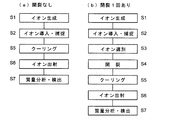
図2は本実施例のIT−TOFMSを用いた分析手順のフローチャートである。図2(a)は開裂操作を実施しない場合、図2(b)は1回の開裂操作を実施する場合、つまりMS/MS分析を行う場合である。これらフローチャートに従って、本実施例の質量分析装置の基本的な動作を説明する。 FIG. 2 is a flowchart of an analysis procedure using the IT-TOFMS of this embodiment. FIG. 2A shows a case where no cleavage operation is performed, and FIG. 2B shows a case where a single cleavage operation is performed, that is, a case where MS / MS analysis is performed. The basic operation of the mass spectrometer of the present embodiment will be described according to these flowcharts.
まず、開裂操作を行わない通常のMS分析動作について説明する。イオン化部1は目的試料の成分分子又は原子を所定のイオン化法によりイオン化する(ステップS1)。生成されたイオンはイオンガイド2によって輸送され、イオン導入口33を通してイオントラップ3内に導入されてその内部に捕捉される(ステップS2)。通常、イオントラップ3へイオンを導入する際には、電圧切替部64により直流電圧発生部61とエンドキャップ電極32、34とが接続され、入射側のエンドキャップ電極32にはイオンガイド2から送られてくるイオンを引き込むような直流電圧が印加され、出射側のエンドキャップ電極34にはイオントラップ3に入射したイオンが押し戻されるような直流電圧が印加される。 First, a normal MS analysis operation in which the cleavage operation is not performed will be described. The ionization unit 1 ionizes component molecules or atoms of the target sample by a predetermined ionization method (step S1). The generated ions are transported by the ion guide 2, introduced into the
イオン化部1がMALDIのようにパルス状にイオンを生成するものである場合には、到来するイオンパケットをイオントラップ3内に取り込んだ直後にリング電極31に高周波高電圧を印加することでイオンを捕捉する。またイオン化部1が大気圧イオン化法のようにほぼ連続的にイオンを生成するものである場合、イオンガイド2のロッド電極の一部に抵抗体をコートすることにより、イオンガイド2末端部に電位の窪みを形成し、その窪みにイオンを一時的に蓄積し、短時間に圧縮してイオントラップ3に導入するようにすることができる(例えば非特許文献1のp.3−5参照)。リング電極31に印加される高周波高電圧は、例えば周波数が500[kHz]、振幅が100[V]〜数[kV]である。この振幅は捕捉するイオンのm/zの範囲に応じて適宜定められる。 When the ionization unit 1 generates ions in a pulse shape like MALDI, the ion is generated by applying a high frequency high voltage to the
イオントラップ3内にイオンを蓄積した後に、ガス導入部7よりクーリングガスをイオントラップ3内に導入し、後述するように今度はエンドキャップ電極32、34に高周波高電圧を印加することで形成した四重極電場によりイオンを捕捉しつつイオンをクーリングする(ステップS5)。所定時間クーリングを実施した後に、エンドキャップ電極32、34間に直流高電圧を印加することでイオンに初期加速エネルギーを付与し、イオン出射口35を通してイオンを出射させTOFMS4に導入する(ステップS6)。同一の加速電圧により加速されたイオンはm/zが小さいほど大きな速度を有するから、先行して飛行してイオン検出器43に到達して検出される(ステップS7)。イオントラップ3からのイオンの出射時点を起点としてイオン検出器43からの検出信号を時間経過に伴って記録すると、飛行時間とイオン強度との関係を示し飛行時間スペクトルが得られる。飛行時間はイオンのm/zと対応するから、飛行時間をm/zに換算することで質量スペクトルが作成される。 After accumulating ions in the
次にMS/MS分析を行う場合の動作を説明する。この場合、上記ステップS2とS5の間に、ステップS3、S4の処理(操作)が実行される。即ち、ステップS2で様々なm/zを有する各種イオンをイオントラップ3内に捕捉した後に、電圧切替部64により高周波低電圧発生部62とエンドキャップ電極32、34とを接続し、プリカーサイオンとして残したいイオンのm/zに対応した周波数にノッチを有する周波数成分を持つ小振幅の高周波電圧をエンドキャップ電極32、34間に印加する。これにより、ノッチ周波数に対応するm/z以外のm/zを持つイオンは励振され、大きく振動してイオン導入口33及びイオン出射口35から排出されてしまったりエンドキャップ電極32、34内面に衝突したりして消滅する。このようにして特定のm/zを有するイオンが選択的にイオントラップ3内に残される(ステップS3)。このとき、リング電極31には、引き続いて高周波高電圧が印加される。 Next, the operation when performing MS / MS analysis will be described. In this case, the processes (operations) of steps S3 and S4 are executed between steps S2 and S5. That is, after various ions having various m / z are captured in the
その後に、ガス導入部7によりCIDガスをイオントラップ3内に導入し、プリカーサイオンのm/zに応じた周波数を持つ小振幅の高周波電圧をエンドキャップ電極32、34間に印加する。すると、運動エネルギーを付与されたプリカーサイオンが励振してCIDガスに衝突し、開裂を生じてプロダクトイオンを生成する(ステップS4)。こうして生成させたプロダクトイオンは元のプリカーサイオンよりもm/zが小さくなるから、こうした低m/zのイオンも捕捉できるようにリング電極31に印加する高周波高電圧の振幅を定めておく。捕捉したプロダクトイオンをステップS5でクーリングした後にイオントラップ3から出射させて質量分析に供する。 Thereafter, CID gas is introduced into the
なお、2回以上のイオン選別と開裂操作を伴うMSn分析を実行する際には、図2(b)においてステップS3、S4を複数回繰り返せばよい。In addition, when performing MS n analysis with ion selection and cleavage operation two or more times, steps S3 and S4 in FIG. 2B may be repeated a plurality of times.
次に本実施例のIT−TOFMSに特徴的な動作について説明する。上記ステップS5のクーリング行程においては、従来、ステップS2のイオン捕捉時やステップS3のイオン選別時などと同様に、リング電極31に高周波高電圧を印加することでイオンを捕捉していた。これに対し、この実施例のIT−TOFMSでは、リング電極31でなくエンドキャップ電極32、34に高周波高電圧を印加し、それによってイオントラップ3内に捕捉用の四重極電場を発生させている。このとき一般的にはリング電極31への電圧印加は停止し、リング電極31を接地電位にする。なお、励振用の高周波低電圧をエンドキャップ電極32、34に印加する場合とは異なり、両エンドキャップ電極32、34には同位相の高周波高電圧を印加する。 Next, operations characteristic of the IT-TOFMS of this embodiment will be described. In the cooling process of step S5, conventionally, ions are trapped by applying a high frequency high voltage to the
このときエンドキャップ電極32、34に印加する高周波高電圧の周波数は適宜に定めることができるが、リング電極31へ印加される高周波高電圧の周波数よりも高い、例えば2倍の1[MHz]とすることができる。上記(2)式から、同じqz値を維持するためには周波数を2倍にした場合に振幅を4倍にする必要がある。例えば最低質量(LMC)を200にしたい場合、高周波高電圧の周波数が500[kHz]である場合には振幅を400[V]程度とすればよいが、高周波高電圧の周波数が2倍の1[MHz]である場合には振幅を4倍の1.6[kV]程度に上げる必要がある。一方、擬電位ポテンシャルは、(1)式で明らかなように、qz値よりも振幅を上げた影響が強く現れ、周波数を2倍、振幅を4倍とすると、擬電位ポテンシャルは4倍大きくなる。At this time, the frequency of the high frequency high voltage applied to the
このようにエンドキャップ電極32、34に印加する高周波高電圧を定めることにより、擬電位ポテンシャルが大きくなると、クーリングガスとの衝突により運動エネルギーを失ったイオンはイオントラップ3の中心に集まり易くなる。つまり、イオンの空間分布が狭くなり、引き続いてエンドキャップ電極32、34間に直流高電圧を印加し、イオンに運動エネルギーを付与して飛行開始させる際のイオンの初期位置のばらつきが小さくなる。その結果、TOFMS4での質量分析の際の質量分解能が高くなり、質量ずれも抑制することができる。 By determining the high frequency high voltage applied to the
なお、上記実施例は本発明の一例にすぎず、本発明の趣旨の範囲で適宜、変形、追加、修正を行っても本願請求の範囲に包含されることは当然である。 The above-described embodiment is merely an example of the present invention, and it is obvious that modifications, additions, and modifications are appropriately included in the scope of the present application within the scope of the present invention.
Claims (2)
a)リング電極に振幅が100[V]以上であるイオン捕捉用の高周波高電圧を印加するリング電圧印加手段と、
b)エンドキャップ電極に振幅が100[V]以上である高周波高電圧と直流電圧とを選択的に印加するエンドキャップ電圧印加手段と、
c)イオントラップ内にクーリングガスを導入するガス導入手段と、
d)前記リング電圧印加手段からリング電極に高周波高電圧を印加することによりイオントラップ内に分析対象イオンを捕捉した状態で、前記ガス導入手段によりクーリングガスを該イオントラップ内に導入するとともに、前記リング電極への電圧印加を停止する一方、前記エンドキャップ電圧印加手段により前記一対のエンドキャップ電極に同位相の高周波高電圧を印加することでイオンのクーリングを実行し、その後に、前記エンドキャップ電圧印加手段により前記エンドキャップ電極に直流電圧を印加しイオンに運動エネルギーを付与してイオントラップから出射させる制御手段と、
を備えることを特徴とする質量分析装置。In a mass spectrometer comprising: an ion trap composed of a ring electrode and a pair of end cap electrodes; and a time-of-flight mass analyzer that performs mass analysis of ions emitted from the ion trap.
a) a ring voltage applying means for applying a high frequency high voltage for ion trapping having an amplitude of 100 [V] or more to the ring electrode;
b) an end cap voltage applying means for selectively applying a high frequency high voltage and a DC voltage having an amplitude of 100 [V] or more to the end cap electrode;
c) gas introduction means for introducing cooling gas into the ion trap;
while capturing the analyte ions in the ion trap by applying a high-frequency high voltage from d) the ring voltage applying means to the ring electrode, a cooling gas is introduced into the ion trap by the gas introduction means, wherein While stopping the voltage application to the ring electrodes, the end cap voltage applying means applies an in- phase high frequency high voltage to the pair of end cap electrodes to perform ion cooling, and then the end cap voltage A control means for applying a DC voltage to the end cap electrode by an applying means to impart kinetic energy to the ions and to emit the ions from the ion trap;
A mass spectrometer comprising:
クーリング実行時に前記エンドキャップ電圧印加手段によりエンドキャップ電極に印加する高周波高電圧の周波数を、前記リング電圧印加手段によるイオン捕捉用の高周波高電圧の周波数よりも高い周波数に設定しておくことを特徴とする質量分析装置。The mass spectrometer according to claim 1,
The frequency of the high frequency high voltage applied to the end cap electrode by the end cap voltage applying means during cooling is set higher than the frequency of the high frequency high voltage for ion trapping by the ring voltage applying means. Mass spectrometer.
Applications Claiming Priority (1)
| Application Number | Priority Date | Filing Date | Title |
|---|---|---|---|
| PCT/JP2008/001602 WO2009153841A1 (en) | 2008-06-20 | 2008-06-20 | Mass analyzer |
Publications (2)
| Publication Number | Publication Date |
|---|---|
| JPWO2009153841A1 JPWO2009153841A1 (en) | 2011-11-17 |
| JP5158196B2 true JP5158196B2 (en) | 2013-03-06 |
Family
ID=41433772
Family Applications (1)
| Application Number | Title | Priority Date | Filing Date |
|---|---|---|---|
| JP2010517557A Active JP5158196B2 (en) | 2008-06-20 | 2008-06-20 | Mass spectrometer |
Country Status (5)
| Country | Link |
|---|---|
| US (1) | US8754368B2 (en) |
| EP (1) | EP2309531B1 (en) |
| JP (1) | JP5158196B2 (en) |
| CN (1) | CN102067275B (en) |
| WO (1) | WO2009153841A1 (en) |
Families Citing this family (16)
| Publication number | Priority date | Publication date | Assignee | Title |
|---|---|---|---|---|
| GB0817433D0 (en) * | 2008-09-23 | 2008-10-29 | Thermo Fisher Scient Bremen | Ion trap for cooling ions |
| JP5533612B2 (en) * | 2010-12-07 | 2014-06-25 | 株式会社島津製作所 | Ion trap time-of-flight mass spectrometer |
| WO2012137806A1 (en) * | 2011-04-04 | 2012-10-11 | 株式会社島津製作所 | Mass spectrometry device and mass spectrometry method |
| US9218948B2 (en) * | 2012-03-22 | 2015-12-22 | Shimadzu Corporation | Mass spectrometer |
| DE102012013038B4 (en) | 2012-06-29 | 2014-06-26 | Bruker Daltonik Gmbh | Eject an ion cloud from 3D RF ion traps |
| US9818593B2 (en) | 2012-09-13 | 2017-11-14 | University Of Maine System Board Of Trustees | Radio-frequency ionization of chemicals |
| GB201409074D0 (en) * | 2014-05-21 | 2014-07-02 | Thermo Fisher Scient Bremen | Ion ejection from a quadrupole ion trap |
| CN104658850B (en) * | 2015-02-16 | 2016-05-11 | 中国科学院地质与地球物理研究所 | Experimental rig and the method for designing thereof in a kind of novel electron bombarding ion source |
| JP6477902B2 (en) * | 2015-09-29 | 2019-03-06 | 株式会社島津製作所 | Liquid sample introduction system and analysis system for ion source |
| JP6705553B2 (en) * | 2017-03-07 | 2020-06-03 | 株式会社島津製作所 | Ion trap device |
| US11075067B2 (en) * | 2017-04-10 | 2021-07-27 | Shimadzu Corporation | Ion analysis device and ion dissociation method |
| CN109300766B (en) * | 2018-08-09 | 2024-03-29 | 金华职业技术学院 | Molecular photoreaction testing method |
| CN108987241B (en) * | 2018-08-09 | 2024-01-30 | 金华职业技术学院 | Molecular light reaction testing device |
| CN110277302B (en) * | 2019-06-28 | 2021-06-15 | 清华大学深圳研究生院 | Ion trap and method for improving ion binding efficiency |
| US11887833B2 (en) * | 2019-09-27 | 2024-01-30 | Shimadzu Corporation | Ion trap mass spectrometer, mass spectrometry method and non-transitory computer readable medium storing control program |
| JP7409260B2 (en) * | 2020-08-19 | 2024-01-09 | 株式会社島津製作所 | Mass spectrometry method and mass spectrometer |
Citations (1)
| Publication number | Priority date | Publication date | Assignee | Title |
|---|---|---|---|---|
| JP2004206933A (en) * | 2002-12-24 | 2004-07-22 | Hitachi High-Technologies Corp | Mass spectrometer and mass spectrometric method |
Family Cites Families (6)
| Publication number | Priority date | Publication date | Assignee | Title |
|---|---|---|---|---|
| JP3480409B2 (en) * | 2000-01-31 | 2003-12-22 | 株式会社島津製作所 | Ion trap type mass spectrometer |
| GB0031342D0 (en) * | 2000-12-21 | 2001-02-07 | Shimadzu Res Lab Europe Ltd | Method and apparatus for ejecting ions from a quadrupole ion trap |
| US6838665B2 (en) * | 2002-09-26 | 2005-01-04 | Hitachi High-Technologies Corporation | Ion trap type mass spectrometer |
| JP3800178B2 (en) | 2003-01-07 | 2006-07-26 | 株式会社島津製作所 | Mass spectrometer and mass spectrometry method |
| GB0416288D0 (en) | 2004-07-21 | 2004-08-25 | Micromass Ltd | Mass spectrometer |
| JP2008091199A (en) * | 2006-10-02 | 2008-04-17 | Shimadzu Corp | Mass spectrometer |
-
2008
- 2008-06-20 CN CN200880129936.7A patent/CN102067275B/en not_active Expired - Fee Related
- 2008-06-20 JP JP2010517557A patent/JP5158196B2/en active Active
- 2008-06-20 US US12/999,957 patent/US8754368B2/en not_active Expired - Fee Related
- 2008-06-20 WO PCT/JP2008/001602 patent/WO2009153841A1/en active Application Filing
- 2008-06-20 EP EP08764185.8A patent/EP2309531B1/en not_active Not-in-force
Patent Citations (1)
| Publication number | Priority date | Publication date | Assignee | Title |
|---|---|---|---|---|
| JP2004206933A (en) * | 2002-12-24 | 2004-07-22 | Hitachi High-Technologies Corp | Mass spectrometer and mass spectrometric method |
Also Published As
| Publication number | Publication date |
|---|---|
| CN102067275B (en) | 2014-03-12 |
| US8754368B2 (en) | 2014-06-17 |
| EP2309531A4 (en) | 2013-11-20 |
| CN102067275A (en) | 2011-05-18 |
| WO2009153841A1 (en) | 2009-12-23 |
| EP2309531A1 (en) | 2011-04-13 |
| EP2309531B1 (en) | 2017-08-09 |
| US20110095180A1 (en) | 2011-04-28 |
| JPWO2009153841A1 (en) | 2011-11-17 |
Similar Documents
| Publication | Publication Date | Title |
|---|---|---|
| JP5158196B2 (en) | Mass spectrometer | |
| JP5001965B2 (en) | Mass spectrometer | |
| JP5081436B2 (en) | Mass spectrometer and mass spectrometry method | |
| JP4223937B2 (en) | Mass spectrometer | |
| JP5623428B2 (en) | Mass spectrometer for MS / MS / MS | |
| JP4918846B2 (en) | Mass spectrometer and mass spectrometry method | |
| JP4636943B2 (en) | Mass spectrometer | |
| JP5603246B2 (en) | Mass spectrometer | |
| US7759641B2 (en) | Ion trap mass spectrometer | |
| JP4463978B2 (en) | Method and apparatus for selective collision-induced dissociation of ions in a quadrupole ion guide | |
| JP2005044594A (en) | Mass spectrometer | |
| US20120138788A1 (en) | Ion Trap Time-Of-Flight Mass Spectrometer | |
| JP2011023184A (en) | Mass spectrometer and mass spectrometry method | |
| US9576779B2 (en) | System and method for quantitation in mass spectrometry | |
| JP3496458B2 (en) | Ion trap mass spectrometer and ion trap mass spectrometry method | |
| US20220384173A1 (en) | Methods and Systems of Fourier Transform Mass Spectrometry | |
| CN113366609A (en) | Automatic gain control for optimized ion trap fill | |
| CN113366608A (en) | Fourier transform mass spectrometer and method of analysis using the same | |
| JP5206605B2 (en) | Ion trap mass spectrometer | |
| JP2009146913A (en) | Mass spectrometer |
Legal Events
| Date | Code | Title | Description |
|---|---|---|---|
| A131 | Notification of reasons for refusal |
Free format text: JAPANESE INTERMEDIATE CODE: A131 Effective date: 20120807 |
|
| A521 | Request for written amendment filed |
Free format text: JAPANESE INTERMEDIATE CODE: A523 Effective date: 20121005 |
|
| TRDD | Decision of grant or rejection written | ||
| A01 | Written decision to grant a patent or to grant a registration (utility model) |
Free format text: JAPANESE INTERMEDIATE CODE: A01 Effective date: 20121113 |
|
| A61 | First payment of annual fees (during grant procedure) |
Free format text: JAPANESE INTERMEDIATE CODE: A61 Effective date: 20121126 |
|
| R151 | Written notification of patent or utility model registration |
Ref document number: 5158196 Country of ref document: JP Free format text: JAPANESE INTERMEDIATE CODE: R151 |
|
| FPAY | Renewal fee payment (event date is renewal date of database) |
Free format text: PAYMENT UNTIL: 20151221 Year of fee payment: 3 |