WO2009150849A1 - Network monitoring device, bus system monitoring device, method and program - Google Patents
Network monitoring device, bus system monitoring device, method and program Download PDFInfo
- Publication number
- WO2009150849A1 WO2009150849A1 PCT/JP2009/002660 JP2009002660W WO2009150849A1 WO 2009150849 A1 WO2009150849 A1 WO 2009150849A1 JP 2009002660 W JP2009002660 W JP 2009002660W WO 2009150849 A1 WO2009150849 A1 WO 2009150849A1
- Authority
- WO
- WIPO (PCT)
- Prior art keywords
- monitoring
- unit
- repeater
- monitoring frequency
- frequency
- Prior art date
Links
Images


Classifications
-
- H—ELECTRICITY
- H04—ELECTRIC COMMUNICATION TECHNIQUE
- H04N—PICTORIAL COMMUNICATION, e.g. TELEVISION
- H04N7/00—Television systems
- H04N7/18—Closed-circuit television [CCTV] systems, i.e. systems in which the video signal is not broadcast
- H04N7/183—Closed-circuit television [CCTV] systems, i.e. systems in which the video signal is not broadcast for receiving images from a single remote source
- H04N7/185—Closed-circuit television [CCTV] systems, i.e. systems in which the video signal is not broadcast for receiving images from a single remote source from a mobile camera, e.g. for remote control
-
- H—ELECTRICITY
- H04—ELECTRIC COMMUNICATION TECHNIQUE
- H04L—TRANSMISSION OF DIGITAL INFORMATION, e.g. TELEGRAPHIC COMMUNICATION
- H04L43/00—Arrangements for monitoring or testing data switching networks
- H04L43/08—Monitoring or testing based on specific metrics, e.g. QoS, energy consumption or environmental parameters
- H04L43/0852—Delays
- H04L43/0864—Round trip delays
-
- H—ELECTRICITY
- H04—ELECTRIC COMMUNICATION TECHNIQUE
- H04L—TRANSMISSION OF DIGITAL INFORMATION, e.g. TELEGRAPHIC COMMUNICATION
- H04L43/00—Arrangements for monitoring or testing data switching networks
- H04L43/10—Active monitoring, e.g. heartbeat, ping or trace-route
- H04L43/103—Active monitoring, e.g. heartbeat, ping or trace-route with adaptive polling, i.e. dynamically adapting the polling rate
-
- H—ELECTRICITY
- H04—ELECTRIC COMMUNICATION TECHNIQUE
- H04L—TRANSMISSION OF DIGITAL INFORMATION, e.g. TELEGRAPHIC COMMUNICATION
- H04L43/00—Arrangements for monitoring or testing data switching networks
- H04L43/12—Network monitoring probes
-
- H—ELECTRICITY
- H04—ELECTRIC COMMUNICATION TECHNIQUE
- H04N—PICTORIAL COMMUNICATION, e.g. TELEVISION
- H04N7/00—Television systems
- H04N7/18—Closed-circuit television [CCTV] systems, i.e. systems in which the video signal is not broadcast
- H04N7/181—Closed-circuit television [CCTV] systems, i.e. systems in which the video signal is not broadcast for receiving images from a plurality of remote sources
-
- H—ELECTRICITY
- H04—ELECTRIC COMMUNICATION TECHNIQUE
- H04L—TRANSMISSION OF DIGITAL INFORMATION, e.g. TELEGRAPHIC COMMUNICATION
- H04L43/00—Arrangements for monitoring or testing data switching networks
- H04L43/02—Capturing of monitoring data
-
- H—ELECTRICITY
- H04—ELECTRIC COMMUNICATION TECHNIQUE
- H04L—TRANSMISSION OF DIGITAL INFORMATION, e.g. TELEGRAPHIC COMMUNICATION
- H04L43/00—Arrangements for monitoring or testing data switching networks
- H04L43/08—Monitoring or testing based on specific metrics, e.g. QoS, energy consumption or environmental parameters
- H04L43/0805—Monitoring or testing based on specific metrics, e.g. QoS, energy consumption or environmental parameters by checking availability
- H04L43/0817—Monitoring or testing based on specific metrics, e.g. QoS, energy consumption or environmental parameters by checking availability by checking functioning
-
- H—ELECTRICITY
- H04—ELECTRIC COMMUNICATION TECHNIQUE
- H04L—TRANSMISSION OF DIGITAL INFORMATION, e.g. TELEGRAPHIC COMMUNICATION
- H04L43/00—Arrangements for monitoring or testing data switching networks
- H04L43/08—Monitoring or testing based on specific metrics, e.g. QoS, energy consumption or environmental parameters
- H04L43/0876—Network utilisation, e.g. volume of load or congestion level
- H04L43/0888—Throughput
Definitions
- the present invention relates to a communication apparatus, a communication method, and a program provided with a communication state monitoring technique for a data transmission path in a packet switching network represented by an IP network or a wireless ad hoc network.
- Throughput is used as one of the indexes for representing the state of a communication path when data is transferred from a transmitter to a receiver in a conventional bandwidth sharing type packet switching network such as the Internet, an intranet, and a wireless IP network. It is done. Throughput is the amount of execution transfer per unit time of the communication path measured between the transmission end and the reception end, expressed as the number of bits transferred per second, and bps is often used as the unit.
- traffic that a user is currently paying attention to such as a specific video in a video transmission system that transmits video from various locations captured by a plurality of street cameras, is called observed traffic. All other traffic that can affect the traffic is referred to as cross traffic.
- Cross traffic includes not only traffic generated by another application, but also traffic generated by other cameras not currently focused on the same video transmission system.
- the link throughput between each repeater located on the communication path from the transmitter to the receiver is not always constant in time but usually fluctuates.
- the main factor of the fluctuation of the throughput of the link between the repeaters is that the resources of the link that can be used for transferring the observation traffic fluctuate due to the influence of the temporal fluctuation of the cross traffic.
- the transmitter sequentially detects fluctuations in the throughput of the transmission path and performs transmission rate control according to the path state.
- the first conventional technique for roughly monitoring the receiver and the second conventional technique for monitoring the repeater on the path Technology exists.
- TFRC TCP Friendly Rate Control
- IETF Internet Engineering Task Force
- FIG. 35 shows streaming distribution of video data from the transmitter A to the receiver B.
- the transmitter A divides the video data to be transmitted and stores it in a UDP (User Datagram Protocol) packet. Send to B.
- UDP User Datagram Protocol
- Receiver B calculates the reception loss rate (LOSS), which is the degree of packet loss per unit time, by statistically measuring the received packets.
- the round trip propagation delay time (RTT) of the communication path between the transmitter A and the receiver B is also calculated based on the time stamp indicating the transmission time and the time stamp of the reception time.
- the receiver B stores the round-trip propagation delay time and the reception loss rate in the measurement packet in accordance with a predetermined time period, and feeds back to the transmitter A, thereby transmitting the transmission state of the communication path to the transmitter A.
- the transmitter A that has received the measurement packet controls the transmission rate according to Equation 1 from the reception loss rate and the round-trip propagation delay time.
- R is a transmission rate
- MTU Maximum Transmission Unit
- T 0 is a timeout period of a TCP (Transmission Control Protocol) session.
- Patent Document 1 discloses a method of fixedly monitoring a repeater having the smallest physical band as a method of selecting a repeater to be monitored.
- An existing bandwidth estimation technique such as a one-packet estimation method is used to estimate the physical bandwidth of each repeater.
- Patent Document 2 discloses a method of selecting and monitoring a repeater that tends to be congested based on the history information of the transmission state of each repeater.
- FIG. 36 is a diagram showing a state in which a data transmission application is activated on the P2P network in Patent Document 2.
- the data transmission application includes a transmission program that operates on the peer 1, a transmission data relay program that operates on the peer 2, the peer 3, and the peer 4, and a reception program that operates on the peer 5, each of which includes a transmitter, It corresponds to a repeater and a receiver.
- On the transmitter A a quality information table in which the quality information of each repeater is recorded is managed, and the repeater numbers are sorted according to the poor transmission quality indicated by the quality information.
- the quality information an estimated load for each repeater estimated using the pair packet estimation method is used as an example.
- the transmitter A reexamines the quality information with respect to a certain number of repeaters recorded in the upper level of the quality information table, updates the quality information table using the result, and sorts again. . Assuming that a certain number is 3, and in the order from the top of the quality information table, assuming that the repeater 3, the repeater 6, the repeater 1, the repeater 4,. At the next cycle timing, the load level is measured for the three units of the repeater 3, the repeater 6, and the repeater 1 by using the pair packet estimation method. The measurement results are written at the corresponding positions in the quality information table and sorted again.
- the repeaters are sequentially arranged from the top of the quality information table. 3, repeater 6, repeater 4, and repeater 1.
- the upper part of the quality information table fluctuates with time, so that it follows dynamic load changes of the repeater.
- the problem with the first prior art in monitoring fluctuations in throughput is low real-time performance.
- the transmission time stamp and the reception time stamp of the probe packet are required.
- the timing at which the transmitter detects a change in throughput differs greatly from the timing at which cross traffic actually occurs, and it was not possible to detect a throughput change with high real-time characteristics.
- the responsiveness is higher than that in the first prior art in which the receiver is monitored.
- This method is characterized in that, among all the repeaters existing on the route, which repeater is to be monitored.
- a repeater with the smallest physical communication band is specified and fixedly monitored.
- a problem when such a fixed monitoring method is adopted is that it is impossible to detect a variation in throughput generated for a repeater not selected as a monitoring target.
- the monitoring accuracy may be reduced.
- the monitoring target is selected in accordance with the variation in throughput, not fixed monitoring.
- the condition for remeasurement becomes stricter as it becomes a lower repeater in the quality information table, and the time required for remeasurement is growing.
- the quality of all repeaters recorded at the higher order is improved and remeasured. It is selected as a target and needs to be placed at the top of the quality information table by sort processing. For this reason, there is a problem that the real-time property is lowered when the remeasurement target number is set small.
- the ratio of measurement packets to the throughput is This will increase the network resource utilization efficiency.
- the overhead due to the measurement packet becomes a problem particularly in a network with limited communication resources such as a wireless IP network.
- the first invention described in the present application is for solving the problems found in the above-described network monitoring technology, can quickly catch a congestion sign on a transmission path in a network system, and is resistant to fluctuations in cross traffic.
- the purpose is to realize a network monitoring technology suitable for use in a wireless infrastructure having low network performance.
- problems corresponding to excess communication capacity due to throughput fluctuations in the network system and the accompanying deterioration in communication quality may occur in the bus system in the semiconductor processor.
- the architecture of a SoC (System on Chip) or multi-core processor is to perform a series of signal processing by connecting a plurality of cores such as CPU, DSP, RISC, and GPU via a bus system.
- the cores are connected by a dedicated bus and handshaked by a high-speed control signal.
- the cores in the bus system and the buses between the cores correspond to peers in the network system and links between the peers, respectively.
- the second invention described in the present application is for solving the problems found in the throughput fluctuation detection technology in such a bus system, and catches a sign of excess of the transfer capability on the data transfer bus in the semiconductor processor at high speed. It is possible to realize a bus system monitoring technology that can withstand fluctuations in the data generation status of each core.
- a network monitoring apparatus is a network monitoring apparatus that monitors a network that transmits data via a plurality of repeaters, and monitors a transmission state monitoring frequency of each repeater.
- the selection probability generation unit that generates selection probability information that is a predetermined probability value for each of the repeaters, the monitoring frequency and the selection probability information of the plurality of repeaters
- a monitoring target identifying unit that identifies a repeater that is to be monitored for a transmission state, a transmission state obtaining unit that acquires transmission state information indicating a transmission state in the repeater identified by the monitoring target identifying unit, and
- the monitoring target specifying unit acquires the transmission state from the monitoring frequency of each repeater existing on the data transmission path recorded in the monitoring frequency recording unit and the selection probability information output by the selection probability generation unit. A repeater is selected, but this selection is performed probabilistically.
- the selection process of each repeater selects with high probability for repeaters with poor transmission status due to the difference in monitoring frequency, but also with low probability for repeaters with good transmission status .
- the selection probability information adds a random probability element to the selection probability distribution determined from the monitoring frequency.
- transmission status information is not frequently acquired for a large number of repeaters, and repeater sequences determined by the monitoring target specifying unit are sequentially monitored, thereby suppressing an increase in the number of measurement packets. Even in a wireless IP network composed of low-speed links, repeater monitoring can be realized without increasing the load on the network.
- the bus system monitoring apparatus of the present invention is a bus system monitoring apparatus that connects a plurality of signal processing units and monitors a bus system that transmits data processed by the plurality of signal processing units.
- a monitoring frequency recording unit that records the monitoring frequency of the data generation status of the processing unit, a selection probability generation unit that generates selection probability information that is a predetermined probability value for each signal processing unit, the monitoring frequency and the selection According to the probability information, a monitoring target specifying unit that specifies a signal processing unit to be monitored for data generation status, and generated data amount information indicating the data generation status in the signal processing unit specified by the monitoring target specifying unit is acquired.
- activity calculation section that calculates the activity representing the accuracy of the monitoring, on the basis of the activity
- monitoring frequency updating unit that updates the monitoring frequency recorded on said monitoring frequency recording unit.
- the present invention can be realized not only as such a network monitoring device and a bus system monitoring device, but also as a network monitoring method and a bus system monitoring method. Further, the network monitoring method and the bus system monitoring method can be realized as a program for executing by a computer.
- the monitoring target repeater is selected stochastically, so that it is resistant to unpredictable throughput fluctuations and can be used for monitoring the repeater. It is possible to grasp the transmission path state while minimizing the network load due to the required measurement packet.
- FIG. 1 is a schematic diagram illustrating a configuration of a video transmission system according to the first embodiment.
- FIG. 2 is a diagram for explaining the variation of the throughput value.
- FIG. 3 is a functional block diagram illustrating an example of the configuration of the network monitoring apparatus according to the first embodiment.
- FIG. 4 is a flowchart illustrating an example of the network monitoring process according to the first embodiment.
- FIG. 5 is a flowchart illustrating an example of a transmission state acquisition process in the first embodiment.
- FIG. 6 is a data flow diagram illustrating an example of an RTT measurement operation according to the first embodiment.
- FIG. 7 is a diagram illustrating an example of the format of the measurement packet and the reply packet in the first embodiment.
- FIG. 1 is a schematic diagram illustrating a configuration of a video transmission system according to the first embodiment.
- FIG. 2 is a diagram for explaining the variation of the throughput value.
- FIG. 3 is a functional block diagram illustrating an example of the configuration of the network monitoring apparatus according to the
- FIG. 8 is a diagram illustrating an example of a data structure of the transmission state information table in the first embodiment.
- FIG. 9 is a flowchart illustrating an example of transmission processing according to the first embodiment.
- FIG. 10 is a diagram illustrating a relationship between the monitoring frequency distribution and the transmission load state in the first embodiment.
- FIG. 11 is a diagram illustrating a relationship between the monitoring frequency distribution and the transmission load state in the first embodiment.
- FIG. 12 is a flowchart illustrating an example of activity calculation processing according to the first embodiment.
- FIG. 13 is a flowchart illustrating an example of the monitoring frequency update process according to the first embodiment.
- FIG. 14 is a diagram illustrating an example of a data structure of a monitoring frequency table according to the first embodiment.
- FIG. 15 is a flowchart illustrating an example of the monitoring target specifying process according to the first embodiment.
- FIG. 16 is a diagram illustrating an example of a data structure for recording the normalized monitoring frequency in the first embodiment.
- FIG. 17 is a block diagram showing a configuration of the video encoding SoC in the second embodiment.
- FIG. 18 is a functional block diagram illustrating an example of the configuration of the bus system monitoring apparatus according to the second embodiment.
- FIG. 19 is a flowchart illustrating an example of generated data amount acquisition processing according to the second embodiment.
- FIG. 20 is a timing chart according to the generated data amount transfer request and acquisition according to the second embodiment.
- FIG. 21 is a timing chart according to the generated data amount control request in the second embodiment.
- FIG. 22 is a flowchart illustrating an example of the generated data amount recording process in the second embodiment.
- FIG. 23 is a diagram illustrating an example of a data structure of the generated data amount information table according to the second embodiment.
- FIG. 24 is a flowchart illustrating an example of activity calculation processing according to the second embodiment.
- FIG. 25 is a block diagram illustrating a configuration of a multi-core processor according to the third embodiment.
- FIG. 26 is a diagram illustrating a traffic transmission state according to the third embodiment.
- FIG. 27 is a block diagram showing the configuration of the core processor in the third embodiment.
- FIG. 28 is a block diagram showing an internal configuration of the NoC router in the third embodiment.
- FIG. 29 is a diagram illustrating a format example of a notification request packet in the third embodiment.
- FIG. 30 is a diagram illustrating a format example of a notification packet in the third embodiment.
- FIG. 31 is a block diagram showing the configuration of the VOD system in the fourth embodiment.
- FIG. 32 is a block diagram showing a configuration of the VOD server in the fourth embodiment.
- FIG. 33 is a diagram illustrating a change in the transmission state of the PCL modem according to the fourth embodiment.
- FIG. 34 is a diagram illustrating an example of a data structure for recording the monitoring frequency in the fourth embodiment.
- FIG. 35 is a configuration diagram showing an example of a network that performs streaming distribution of conventional video data.
- FIG. 36 is a configuration diagram illustrating an example of a P2P network in which a conventional data transmission application operates.
- FIG. 1 is a schematic diagram showing a configuration of a video transmission system as an example of a monitoring target of a network monitoring apparatus according to Embodiment 1 of the present invention.
- This video transmission system can be used with remote monitoring by installing a camera device in an area that requires safety monitoring, such as a busy street or school road, and transmitting the video captured by the camera device to the center station via the network. It is a kind of crime prevention system that realizes safety support.
- CAM1 to CAM4 are installed at each intersection and are camera devices for capturing images in the intersection, MP1 to MP4 are repeaters installed at each intersection, and MPP1 is an AP (access to the receiving station). These devices are connected by a wireless ad hoc network that is easy to install.
- each camera device The shooting range of each camera device is indicated by a dotted line in FIG. 1, and the video in each intersection captured by CAM1 to CAM4 is transmitted to the nearest repeater, and between the repeaters to the receiving station AP by multi-hop communication. Sent.
- transmission from the receiving station AP to the center station is performed using a bandwidth-guaranteed NGN (New Generation Network) network or the like.
- NGN New Generation Network
- a mesh communication infrastructure such as IEEE 802.11s capable of multi-hop communication can be used.
- the end-to-end throughput value from the camera device as a transmitter to the receiving station access point as a receiver is not constant but fluctuates.
- FIG. 2 is a diagram for explaining such a variation in the throughput value, and shows a state in which data is transmitted from the transmitter A to the receiver B via the four repeaters 1 to 4.
- repeaters 1 to 4 in FIG. 2 transmitter A, and receiver B correspond to repeaters MP1 to MP4, camera device CAM1, and receiving station access point MPP1 in FIG. 1, respectively.
- the repeater 3 Due to the difference in bandwidth allocated to the communication interface of the repeater and the influence of cross traffic, between the transmitter and the repeater 1, between the repeater 1 and the repeater 2, between the repeater 2 and the repeater 3, the repeater 3
- the throughput of each of the five links between the relay 4 and the relay 4 and the receiver is normally different, and the throughput between the transmitter and the receiver is the thinnest link, the relay 3 and the relay 4 The link throughput between them.
- the transmission path of the video transmitted by the camera devices CAM1 to CAM4 is determined by the path control protocol between the repeaters MP1 to MP4.
- the camera video of CAM1 is sent to MPP1 through four repeaters of MP1, MP2, MP3, and MP4 in order.
- the camera video of CAM2 is sent to MPP1 through three repeaters of MP2, MP3, and MP4 in order.
- the camera video of CAM3 is sent to MPP1 via two repeaters of MP3 and MP4 in order.
- the camera video of CAM4 is sent to MPP1 via MP4.
- This transmission path is indicated by an arrow in FIG. Also, the IP address assigned to each device is shown in parentheses in the figure.
- FIG. 3 is a functional block diagram showing a configuration of a main part of the camera devices CAM1 to CAM4 as a transmitter (in particular, a network monitoring device).
- the main part of the camera device is shown as the network monitoring device 100.
- the configuration shown in FIG. 3 is common to all the camera devices CAM1 to CAM4.
- the network monitoring device 100 which is the main part of each camera device, includes a transmission state acquisition unit 106, a transmission state recording unit 107, a transmission unit 108, an activity calculation unit 109, a monitoring frequency update unit 110, a monitoring frequency recording unit 111, and a selection probability.
- the generating unit 112 and the monitoring target specifying unit 113 are configured. In FIG. 3, the illustration of the configuration for realizing the photographing function of the camera device is omitted.
- MP1, MP2, MP3, and MP4 in FIG. 1 correspond to the repeater 101, repeater 102, repeater 103, and repeater 104 in FIG. 3, respectively, and receive access points in FIG. MPP1 corresponds to the receiver 105 in FIG.
- FIG. 4 is a flowchart illustrating an example of processing executed by the network monitoring apparatus 100.
- the transmission state acquisition unit 106 acquires the transmission state (S11), and the acquired transmission state is recorded by the transmission state recording unit 107. (S12). Acquisition of the transmission state is performed by issuing a measurement packet.
- the timing for investigating the state of the transmission path is typically periodic processing, but may be in accordance with other time scheduling.
- the transmission unit 108 detects a change in throughput according to the transmission state of the path, and adjusts transmission conditions such as the bit rate, frame rate, and screen resolution of the video data according to the situation (S13).
- the activity calculation unit 109 calculates the activity based on the degree of correlation between the transmission status information and the current monitoring status (S14), and the monitoring frequency update unit 110 monitors the monitoring frequency of each repeater on the path based on the activity. (S15), and the monitoring frequency recording unit 111 records the updated value (S16).
- the selection probability generation unit 112 generates selection probability information (S17).
- the monitoring target specifying unit 113 determines the monitoring target relay according to the monitoring frequency recorded by the monitoring frequency recording unit 111 and the selection probability information generated by the selection probability generation unit 112 (S18).
- the transmission state acquisition unit 106 acquires transmission state information for the repeater on the transmission path selected by the monitoring target specifying unit 113.
- the transmission status information that can be acquired from the repeater includes various quality measures such as round-trip propagation delay time (RTT), delay fluctuation, packet loss rate, etc.
- RTT round-trip propagation delay time
- it is effective to use an RTT that can detect a sign of congestion before packet loss occurs as transmission state information.
- FIG. 5 is a flowchart illustrating an example of processing executed by the transmission status acquisition unit 106.
- the transmission state acquisition unit 106 reads monitoring target specifying information for specifying the monitoring target repeater from the monitoring target specifying unit 113 (S20). A characteristic method for the monitoring target specifying unit 113 to specify the monitoring target repeater will be described later.
- a measurement packet is issued to the relay specified by the read monitoring target specifying information (S21 to S23), a reply packet is received (S24), and the RTT of the monitoring target relay is calculated (S25).
- FIG. 6 is a data flow diagram showing an example of an RTT measurement operation. In FIG. 6, the process shown in FIG. 5 is performed three times.
- the repeater MP2 is specified as the monitoring target repeater
- the repeater MP4 is specified as the monitoring target repeater
- the repeater MP1 is specified as the monitoring target.
- the camera device CAM1 issues a measurement packet to the identified monitoring target repeater and receives a reply packet.
- FIG. 7 is a diagram showing an example of the format of the measurement packet and the reply packet. As shown in FIG. 7, Echo Request and Echo Reply implemented in the ICMP protocol can be used as the measurement packet and the reply packet.
- the camera device CAM1 records the transmission time of the measurement packet in the REQ TIME field in the Echo Request, and the monitored repeater copies the contents of the received REQ TIME field in the Echo Request to the REQ TIME field in the Echo Reply. And reply.
- the camera device 1 that has received Echo Reply can calculate the RTT of the monitoring target repeater by taking the difference between the reception time and the transmission time copied in the REQ TIME field.
- the packet size of the measured packet is adjusted to the packet size for transmitting video data.
- the packet size of the Echo Request packet is adjusted to 1518 bytes by performing stuffing of 1468 bytes.
- the transmission state acquisition unit 106 records the calculated RTT value of the monitoring target repeater in the transmission state information table provided in the transmission state recording unit 107.
- FIG. 8 is a diagram showing an example of the data structure of the transmission status information table.
- the first column records the number of hops counted from the camera side of the repeater on the route.
- the IP address of each repeater is recorded.
- the third column is a route RTT, and the value of RTT acquired by the transmission state acquisition unit 106 is recorded in milliseconds.
- the fourth column is a link RTT, which represents a delay time generated with respect to a round trip between adjacent repeaters, and is an index representing the delay of the repeater itself.
- the link RTT is calculated by subtracting the route RTT of the repeater having one hop less than the repeater from the route RTT of the repeater as the difference of the route RTT. However, for a repeater with a hop count of 1, the route RTT and the link RTT are equal.
- the transmission unit 108 encodes and transmits the captured video, determines an appropriate rate of the observed traffic data based on the transmission state information table, and performs transmission rate control so that the actual transmission rate approaches the appropriate rate. .
- FIG. 9 is a flowchart illustrating an example of processing executed by the transmission unit 108.
- a Motion Picture Expert Group (MBR) VBR (Variable Bitrate) encoding method or the like can be used as a video encoding method.
- MRR Motion Picture Expert Group
- VBR Variable Bitrate
- the maximum value p current of the path RTT is read on the transmission state information table. If the difference from the maximum value p prev of the path RTT at the previous measurement is ⁇ p,
- R current can be controlled according to the following dynamics with respect to R prev , which is the current transmission rate adjusted at the time of the previous measurement.
- K is a coefficient for determining the rate adjustment speed (S33).
- the rate adjustment granularity is limited by the method, but in the case of MPEG2, for example, it can be set in units of 400 bps (S34).
- the target rate calculated by Equation 3 is limited by the minimum bit rate value and the maximum bit rate value specified by the system (S35 to S38), and the code in the transmission unit 108 is set at the target rate after limitation.
- the target rate of the generator is changed (S39).
- (Activity calculation unit 109) 10 and 11 are diagrams illustrating the relationship between the monitoring frequency distribution and the transmission load state.
- the transmission state of the repeaters 1 to 3 is good among the four repeaters on the route, whereas the repeater 4 has a round trip propagation delay time 10 times that of other repeaters.
- the transmission state is bad.
- the repeater that is frequently monitored is the repeater 3, and the repeater 4 is set to the same monitoring frequency as the repeaters 1 and 2 in which the other transmission states are good.
- the monitoring frequency means a probability that the relay is selected as a monitoring target.
- the relationship is such a relationship, it is considered that the monitoring frequency distribution is not suitable for the transmission load state of the repeater on the route, so that the monitoring accuracy is low.
- the monitoring frequency of the relay 4 having a poor transmission state is the highest as compared with other relays, and the monitoring frequency for the other three relays is low.
- the activity ⁇ is an index representing how well the current monitoring frequency distribution for each repeater reflects the transmission load state of the data transmission path.
- FIG. 12 is a flowchart illustrating an example of processing executed by the activity calculation unit 109.
- Activity calculation unit 109 reads the link RTTl i from the transmission status information table (S40), reads the monitoring frequency m i from the monitoring frequency table in the monitoring frequency recording unit 111 (S41), and read link RTT and the monitoring frequency Then, the change in activity ⁇ is calculated according to Equation 4 (S42 to S44).
- Equation 4 is an example of the definition of dynamics of activity ⁇ , where n is the number of repeaters on the transmission path, l i is the link RTT of the repeater with the number of hops i recorded in the transmission state information table, m i Represents the monitoring frequency assigned to the repeater, and N and ⁇ represent constants governing the change rate of the dynamics.
- the term of the product-sum operation for the link RTT and the monitoring frequency indicates the degree of these correlations.
- Equation 7 is a time interval determined by the update cycle.
- the range of the activity ⁇ is limited to a closed section from 0 to 1 for ease of handling (S46 to S49). Due to this limitation, the activity ⁇ is a real value between 0 and 1.
- a state where the activity ⁇ is close to 0 corresponds to a state where the monitoring accuracy is low
- a state where the activity ⁇ is close to 1 corresponds to a state where the monitoring accuracy is high. This is because, according to the dynamics of Equation 4, the degree of activity ⁇ approaches 1 as the monitoring state distribution for the repeater group of the transmission path is in a desirable state, and the monitoring state distribution is more dissociated from the transmission load state of the repeater. This is because the behavior approaches 0.
- Monitoring frequency updating unit 110 based on the value of the activity calculation unit 109 activity as determined by alpha, updates the monitoring frequency m i for each repeater on the transmission path.
- FIG. 13 is a flowchart illustrating an example of processing executed by the monitoring frequency update unit 110.
- Monitoring frequency updating unit 110 reads the activity calculation section 109 activity determined from alpha (S50), reads the monitoring frequency m i from the monitoring frequency table in the monitoring frequency recording unit 111 (S51), the maximum value of the monitoring frequency m max is searched (S52). Using the read activity ⁇ , monitoring frequency m i , and maximum value m max of the monitoring frequency, a new monitoring frequency of each repeater is calculated (S53 to S56).
- Equation 8 is an example of a definition of the dynamics of the monitoring frequency m i, beta in the equation, gamma, [psi is a constant that controls the rate of change of the dynamics.
- ⁇ T is a time interval determined by the update cycle.
- Monitoring frequency recording unit 111 records the monitoring frequency m i for each repeater on the transmission path calculated by the monitoring frequency updating unit 110 to the monitoring frequency table managed.
- FIG. 14 is a diagram illustrating an example of the data structure of the monitoring frequency table.
- the second column is the IP address
- the third column the value of the monitoring frequency m i of each relay calculated by the monitoring frequency updating unit 110 is recorded.
- Selection probability generator 112 The selection probability generation unit 112 generates selection probability information, which is a random number necessary for adding a stochastic behavior to the selection mechanism, according to the timing at which the monitoring target specifying unit 113 selects the monitoring target repeater.
- the selection probability information is preferably a random number, but may be substituted by a pseudo-random number that is relatively easy to generate.
- the probability distribution used in that case may be a general uniform distribution, Gaussian distribution, or the like.
- the variation range of the selection probability information can be determined from Equation 9 and Equation 10. Considering the case where the degree of activity ⁇ is 0, the distance D between solutions is given by Equation 12.
- the Random function generates a real random number or a pseudo real random number within a specified range, and ⁇ is an adjustment coefficient that takes a value of zero or more.
- the amplitude of the selection probability information generated by increasing ⁇ can be increased.
- FIG. 15 is a flowchart illustrating an example of processing executed by the monitoring target specifying unit 113.
- Monitoring target identification unit 113 reads the monitoring frequency m i of each relay from the monitoring frequency table monitoring frequency recording unit 111 manages, for the corresponding repeater generated by the selection probability generating unit 112 as shown by Equation 14 By adding to the selection probability information ⁇ i , a stochastic behavior is added to the selection of the monitoring target (S60 to S64).
- the updated monitoring frequency of each repeater is normalized by Equation 15 so as to be a probability value (S65 to S67).
- FIG. 16 is a diagram showing an example of a data structure for recording the normalized monitoring frequency obtained in this way.
- the first column is the number of relay hops counted from the transmitter of each repeater
- the second column is the IP address assigned to each repeater
- the third column is the normalized monitoring frequency calculated by Equation 15.
- the monitoring target specifying unit 113 regards the index of the relay to be selected as a probability variable by viewing the normalized monitoring frequency as a probability distribution with respect to the index of each relay, and relays the monitoring target according to the value taken by this random variable.
- a device is selected (S68, S69).
- FIG. 17 is a block diagram illustrating a configuration of a video encoding SoC as an example of a control target of the bus system monitoring apparatus (arbiter) according to the second embodiment of the present invention.
- a data processing framework in video encoding processing standardized by MPEG2 and the like includes decimation processing for reducing the amount of information of an input video signal, preprocessing for reducing noise and band limitation, motion detection processing, time It can be roughly divided into a frequency synthesis analysis process for converting from a domain to a frequency domain, and a video encoding process for performing information compression and code allocation using visual characteristics.
- the video encoding SoC shown in FIG. 17 is an example of a multi-core architecture in which these processes are executed by DSP1, DSP2, DSP3, DSP4, and DSP5, which are independent digital signal processors, and each DSP performs bus transfer. They are connected by independent video data buses VBUS2, VBUS3, VBUS4, and VBUS5 having different speeds.
- the video data to be encoded is accumulated in the input frame buffer BUF1 for color difference signals.
- Video data is first read out by DSP 1 via VBUS 1 and subjected to decimation processing by DSP 1. Then, while passing through VBUS2, VBUS3, VBUS4, and VBUS5, the preprocessing by DPS2, the motion detection processing by DSP3, the frequency component analysis processing by DSP4, and the encoding processing by DSP5 are received, and finally the output frame buffer BUF2 passes through VBUS6 Sent to.
- the arbiter ARB monitors the amount of data generated by each DSP, and adjusts the amount of data generated by the DSP 1 when the transfer rate of the video bus exceeds a threshold value.
- FIG. 18 is a functional block diagram showing a configuration of a main part of the arbiter ARB as a bus system monitoring device.
- the main part of the arbiter ARB is shown as a bus system monitoring device 200.
- functional blocks realized by DSP1 to DSP5 are shown as a decimation processing unit 208, a preprocessing unit 201, a motion detection processing unit 202, a frequency component analysis processing unit 203, and an encoding processing unit 204, respectively.
- the output frame buffer BUF2 is shown as the output frame buffer 205.
- bus system monitoring apparatus 200 of FIG. 18 the same components as those of the network monitoring apparatus 100 (see FIG. 3) are assigned the same symbols, and the description thereof is omitted. Hereinafter, only differences are detailed. Explained.
- the generated data amount acquisition unit 206 acquires the generated data amount information for the signal processors DSP2, DSP3, DSP4, and DSP5 on the video data transmission path selected by the monitoring target specifying unit 113.
- FIG. 19 is a flowchart illustrating an example of processing executed by the generated data amount acquisition unit 206.
- the generated data amount acquisition unit 206 reads monitoring target specifying information for specifying the monitoring target DSP from the monitoring target specifying unit 113 (S70).
- a generated data amount transfer request is transmitted to the DSP specified by the read monitoring target specifying information (S71), and the generated data amount information returned from the DSP is acquired (S72).
- FIG. 20 is a timing chart showing an example of signals transmitted by main signal lines constituting the arbitration bus ABUS at the time of generation data amount transfer request and acquisition.
- the bus system monitoring apparatus 200 transmits an 8-bit wide sub-address corresponding to the DSP to be monitored on the SADDR, and serially transmits an 8-bit wide command designation bit pattern defined as a generated data amount request on the CDATA.
- the subaddress is an 8-bit index assigned to each DSP. For example, 0x01 is assigned to DSP1, 0x02 is assigned to DSP2, 0x03 is assigned to DSP3, 0x04 is assigned to DSP4, and 0x05 is assigned to DSP5.
- the signal line validation timing is detected by the DSP by asserting the command strobe (/ CSTRB).
- the DSP having the designated sub-address generates the 8-bit width generated data amount information on the DATA line and drives the data strobe (/ DSTRB) at the next timing after detecting the negation of / CSTRB.
- the generated data amount information is transferred to the monitoring device 200.
- the generated data amount is defined in the range of 0x00 to 0x64, and the output bus currently assigned The ratio of the actual transfer rate to the maximum transfer rate may be transferred on the DATA line.
- the generated data amount information acquired by the generated data amount acquisition unit 206 is transferred to the generated data amount recording unit 207 and recorded and managed in the generated data amount information table (S73). Details of the processing by the generated data amount recording unit 207 will be described later.
- the generated data amount acquisition unit 206 reads the generated data amount difference value for the DSP having the maximum generated data amount difference value from the generated data amount information table, and calculates the target value of the generated data amount according to Equation 16 (S74 to S75). .
- the calculated target value is transferred to the decimation processing unit 208 according to the timing chart of FIG. At this time, the sub address of the DSP designates 0x01 assigned to the decimation processing unit 208 (S76).
- FIG. 22 is a flowchart illustrating an example of processing executed by the generated data amount recording unit 207.
- the generated data amount recording unit 207 reads the generated data amount information of the monitoring target DSP collected by the generated data amount acquisition unit 206 (S80).
- FIG. 23 is a diagram illustrating an example of the data structure of the generated data amount information table.
- the DSP sub-address is recorded in advance.
- the maximum transfer rate assigned to the output bus of each DSP is recorded in advance, and each DSP adjusts the output bus clock based on this information.
- the generated data amount p current acquired by the generated data amount acquisition unit 206 is recorded, but the generated data amount p prev previously recorded before data writing is read (S81), and the difference is calculated according to Expression 17. A value is obtained and recorded as a generated data amount difference value in the fourth column (S82 to S83).
- the decimation processing unit 208 adjusts the amount of data transferred to the VBUS 2 to an appropriate value based on the generated data amount information table.
- the amount of generated data may be controlled by adjusting the output resolution of the decimation filter for the video signal read from the input frame buffer.
- the effective value as the output resolution is discrete, it is preferable to perform the decimation process with the maximum output resolution that does not exceed the target value specified by the generated data amount acquisition unit 206.
- FIG. 24 is a flowchart illustrating an example of processing executed by the activity calculation unit 209. As shown in FIG. 24, the processing of the activity calculation unit 209 (S90 ⁇ S98), compared with the process of the activity calculation unit 109 (see S40 ⁇ S49 of FIG. 12), the normalized value of the link RTTl i to different in using a normalized value of the generated data amount P i instead of.
- the activity dynamics is defined by the correlation between the normalized monitoring frequency for each DSP and the normalized generated data amount difference, as shown in Equation 19, for example.
- the monitoring target repeater is selected probabilistically in network applications such as media transmission in which the throughput variation leads to a decrease in service quality. By doing so, it is possible to grasp the transmission path state that is resistant to unpredictable throughput fluctuations and minimizes the network load due to the measurement packet required for monitoring the repeater.
- the repeater selection apparatus, method, and program according to the present invention include a repeater that monitors a transmission path status in a data transmission service over an IP network that performs data transmission through multiple stages of repeaters. Because it is determined by taking into account both the load state of the repeater and the stochastic randomness, it is resistant to unpredictable changes in the network state and has the effect of suppressing the measurement load for network state measurement This is effective when applied to a bandwidth sharing type communication system in which the throughput fluctuation of the transmission path is likely to occur due to the influence of other unpredictable service traffic.
- the measurement load for monitoring the network state can be suppressed, when applied to a system constituted by mobile devices whose line usage cost is high, it has the effect of reducing measurement packets and power consumption.
- the present invention is not limited to a network system, and can be applied as a large-scale LSI arbiter control logic having a shared bandwidth bus architecture.
- NoC Network-on-Chip
- FIG. 25 is a block diagram showing an example of a configuration of a mesh type multi-core processor connected by NoC.
- Each core processor is connected to a NoC router, and the NoC routers are connected by a simple bus.
- a NoC router is a functional block that performs data transfer processing like a router in an IP network.
- the NoC router passes through R00 connected to the output port of the CP00, and passes through the R01, R02, R03, R13, R23, and R33, and then arrives at the core processor CP33. Perform route control.
- a normal packet is composed of a plurality of flits including a packet header.
- the address of the core processor of the transmission source and the address of the core processor of the transmission destination are stored in the packet header, and the NoC router crosses the output stage based on the packet header information and the routing information. By controlling the bar switch, the packet is transmitted to an appropriate output port.
- the NoC bus on the processor does not cause flit loss due to router congestion, and stays on the NoC router until the congestion is eliminated.
- the transfer to the core processor of the transfer destination within a desired time due to the stagnation of flits on the path. A situation occurs where necessary data does not arrive. Under such circumstances, a video processing failure occurs and the processing of the processor fails for a certain time.
- the cause of such congestion in the NoC router is unexpected generation of traffic between core processors, which includes estimation errors at the chip design stage, fluctuations in the amount of generated code depending on the original signal to be encoded, and the like. .
- this embodiment takes a form in which data transmission using a plurality of paths is performed from the core processor on the transmission side to the core processor on the reception side, and the NoC on each path.
- FIG. 26 shows a situation in which traffic is transmitted using two paths for data transfer from the core processor CP00 on the transmission side to the core processor CP33 on the reception side.
- two routes are used as a plurality of routes, but more routes may be used.
- the core processor CP00 on the transmission side performs data transfer to the CP 33 using the route passing through R03 as the main route
- the transmission state due to congestion of the main route is determined. Due to the deterioration, the transmission path can be switched to the alternative path through R30. Also, by distributing a part of the amount of data being transmitted on the main route to the alternative route passing through R30, it is possible to guarantee the real-time property of data transfer within a desired time while alleviating congestion on the main route. It becomes possible.
- the configuration of the core processor on the transmission side is shown in FIG.
- the repeater in FIG. 27 corresponds to a NoC router in NoC.
- the transmission-side core processor CP00 of FIG. 27 the same components as those of the network monitoring device 100 (see FIG. 3) are assigned the same symbols and description thereof is omitted, and only the differences are detailed below. Explained.
- the transmission state acquisition unit 106 acquires monitoring target transmission state information from the NoC router that is the monitoring target specified by the monitoring target specifying unit 113. Since the average stay time R of flits in the NoC router is considered as an example of the monitoring target transmission state information, this embodiment will be described using the average stay time.
- the monitoring target transmission status information may use an index other than the average stay time as long as it reflects the load status of the NoC router.
- FIG. 28 shows an internal configuration example of the NoC router.
- a NoC router connected in a two-dimensional mesh topology as shown in FIG. 25 has a total of five input / output ports in four directions, top and bottom, left and right, and a core processor direction directly connected to the NoC router.
- the four input / output ports in the upper, lower, left, and right directions are indicated as X +, X ⁇ , Y +, and Y ⁇ , respectively, and the input / output port in the core processor direction is indicated as Core.
- the flits input from any of these five ports are temporarily stored in the corresponding input buffer 331, and after the port to be output is determined, the crossbar switch 333 in the output stage is switched to appropriately Output to the correct port.
- the stay counter 332 is a mechanism for measuring the average stay time of the flits on the input buffer and notifying the core processor of the traffic transmission source.
- the input buffer is composed of one or a plurality of virtual channels, and the transfer target flits with different ports to be output are prevented from staying in a ripple due to the stay of other flits previously input from the same port.
- the input buffer is composed of two virtual channels VC0 and VC1.
- FIG. 29 shows a format example of a notification request packet issued to a NoC router that is a target for obtaining an average residence time from a core processor that is a traffic transmission source.
- FIG. 30 shows a format example of a notification packet for notifying the average residence time from the NoC router that has received the notification request packet to the core processor of the transmission source.
- the transmission state acquisition unit 106 exchanges these packets to collect the average stay time for all available routes and detect the congestion state of each transmission route.
- the transmission state acquisition unit 106 collects the average stay time of flits in each NoC router on each transmission path.
- the maximum average residence time of the NoC router on the path from the core processor CP00 to the CP33 via the NoC routers R00, R01, R02, R03, R13, R23, R33 is R1, and from the core processor CP00
- R2 be the maximum average residence time of NoC routers on the route from NoC routers R00, R10, R20, R30, R31, R32, and R33 to CP33.
- R1 and R2 are expressed as in Expression 20 and Expression 21.
- P0 and P1 are obtained by normalizing R0 and R1 according to Equation 22.
- the transmission unit 108 regards P0 and P1 in Expression 22 as a path selection probability when transmitting a data packet to the reception-side core processor CP33, and selects a transmission path for each packet.
- Selection probability generator 112 The generation of pseudo-random numbers according to a uniform distribution or a Gaussian distribution may be difficult to implement in an embedded processor for a network application having a small number of gates and a semiconductor or a memory resource.
- the selection probability generation unit 112 As a simple implementation form of the selection probability generation unit 112, a method of storing a series of non-overlapping numeric strings as a list and using them cyclically may be used. For example, a numerical value is cyclically read in order from a list in which 1, 2, 3, 4, 5, 6, and 7 are stored, and the result of the readout is used as a substitute for the pseudo-random number generation result, so that resources for random number calculation can be obtained. It is possible to reduce.
- the selection probability generation unit 112 outputs the numerical value read from the list to the monitoring target specifying unit 113.
- Monitoring target specifying unit 113 When the monitoring target specifying unit 113 specifies the NoC router to be monitored, the monitoring target specifying unit 113 is selected in a situation where the stochastic operation in which the activity calculation unit 109 outputs an activity lower than a predetermined threshold is dominant.
- the NoC router associated with the numerical value input from the probability generation unit 112 is specified as a monitoring target. That is, the NoC routers to be monitored are uniformly selected according to the order of the numerical list stored in the selection probability generation unit.
- R00 is first, R01 is second, R02 is third, R03 is fourth, R13 is fifth, R23 is sixth, R33 is seventh NoC router, and the contents of the list are 1, 2, In the case of 3, 4, 5, 6, 7, NoC routers R00, R01, R02, R03, R13, R23, and R33 are cyclically selected and monitored in this order.
- the configuration of the present invention can be implemented with low resources.
- Such an implementation is also included in the present invention because it expects a uniform distribution effect of the monitoring target.
- FIG. 31 shows a configuration diagram of a business VOD (Video-on-Demand) system using a power line.
- a PLC modem or a relay device existing on the route performs multi-hop transmission, so that a signal form is secured.
- video content is distributed from the VOD server 511 to the viewing monitors 512 to 517.
- the video content is routed through the installed power line to the PLC modem 501, switchboard 500, PLC modem 505, PLC modem 506, PLC modem. It reaches the viewing monitor 517 via 507.
- the VOD server 511 passes through the PLC modem 501, the switchboard 500, the PLC modem 502, the PLC modem 503, the CD section, and the PLC modem 507. In some cases, high-quality data transmission may be possible by using the route to the viewing monitor 517.
- the CD section on this route is not wired by a power line, but when the distance between the power lines laid in parallel is small, the CD is caused by the interference of the signal state between the communication paths. In the meantime, an available radio path is generated.
- the power lines of hotels, buildings, etc. generally have a tree structure topology that spreads around the switchboard, but due to the behavior between distributed constant circuit lines, radio sections are generated, and in reality a mesh structure topology It becomes.
- the selection of the PLC modem to be monitored according to the present invention is probabilistic in the VOD system that transmits video content requiring QoS using multi-hop transmission using such a meshed power line infrastructure. By doing so, it is possible to perform high-quality VOD transmission that is resistant to unpredictable throughput fluctuations and minimizes the overhead of measurement packets required for monitoring transmission quality.
- FIG. 32 is a block diagram showing the configuration of the VOD server 511. Noise superimposed on the power line has a strong correlation with the usage status of electrical appliances connected to the communication path, and often depends on the usage time, usage location, and user life pattern of the appliance. Control of transmission quality using the history of the situation is effective.
- FIG. 33 shows a change pattern of the transmission state for 24 hours of the PLC modems 505, 506, and 507 existing on the path from the VOD server 511 to the viewing monitor 517.
- the load on the PLC modems 505 and 507 is increasing at the 19:00 level, and the load on the PLC modem 505 is still high at the 20:00 level. The load is decreasing. At 21:00, the load on the PLC modem 506 in addition to the PLC modem 505 is increasing.
- the distribution of the periodic load time variation and the number of monitoring times caused by it reflects the influence of the use of electrical appliances, and therefore has reproducibility.
- FIG. 34 shows an example of a data structure for recording the monitoring frequency.
- it has a field for recording the history of the number of monitoring times per unit time for each PLC modem.
- a specific PLC is added to the monitoring frequency for each PLC modem.
- to the modem of the pair may be set the monitoring frequency m i. Even m i newly introduced in this manner as well as other m i, only to be controlled in accordance with equation 8.
- Monitoring frequency updating unit 110 Monitoring frequency updating unit 110, the value of the monitoring frequency m i for a set of PLC modems, normalizes and updates the monitoring frequency m i and the same method for each PLC modem.
- Transmission state acquisition unit 106 When acquiring the transmission status for the set of PLC modems, the transmission status acquisition unit 106 acquires the transmission status for the corresponding PLC modems by using the same method as that shown in FIGS.
- the present invention is applicable to a network that transmits data via a plurality of repeaters and a bus system that connects a plurality of signal processing units and transmits data processed by the plurality of signal processing units.
Abstract
Description
図1は、本発明の実施の形態1におけるネットワーク監視装置の監視対象の一例としての、映像伝送システムの構成を示す模式図である。この映像伝送システムは、繁華街や通学路等の安全監視が必要なエリア内にカメラ装置を設置し、カメラ装置で捉えた映像を、ネットワークを介してセンター局まで送信することで遠隔監視による安心安全支援を実現する防犯システムの一種である。 (Embodiment 1)
FIG. 1 is a schematic diagram showing a configuration of a video transmission system as an example of a monitoring target of a network monitoring apparatus according to
伝送状態取得部106は、監視対象特定部113によって選択された送信経路上の中継器に対して、伝送状態情報の取得を行う。 (Transmission state acquisition unit 106)
The transmission
伝送状態取得部106は、算出した監視対象中継器のRTTの値を、伝送状態記録部107に設けられる伝送状態情報テーブルに記録する。 (Transmission status recording unit 107)
The transmission
送信部108は、撮影された映像を符号化伝送すると共に、伝送状態情報テーブルを基にして観測トラフィックデータの適正レートを決定し、実際の送信レートが適正レートに近づくように伝送レート制御を行う。 (Transmitter 108)
The
図10および図11は、監視頻度分布と伝送負荷状態との関係を示す図である。 (Activity calculation unit 109)
10 and 11 are diagrams illustrating the relationship between the monitoring frequency distribution and the transmission load state.


監視頻度更新部110は、活性度算出部109によって決定された活性度αの値を基に、送信経路上の各中継器に対する監視頻度miを更新する。 (Monitoring frequency update unit 110)
Monitoring


監視頻度記録部111は、監視頻度更新部110によって算出された伝送経路上の各中継器に対応する監視頻度miを監視頻度テーブルに記録、管理する。 (Monitoring frequency recording unit 111)
Monitoring
選択確率生成部112は、監視対象特定部113が監視対象中継器を選択するタイミングに応じて、選択メカニズムに確率的挙動を付加するために必要な乱数である選択確率情報を発生させる。選択確率情報は乱数であることが望ましいが、比較的生成が容易な疑似乱数によって代用してもよい。またその場合に用いる確率分布としては、一般的な一様分布やガウス分布等でよい。 (Selection probability generator 112)
The selection


図15は、監視対象特定部113によって実行される処理の一例を示すフローチャートである。 (Monitoring target specifying unit 113)
FIG. 15 is a flowchart illustrating an example of processing executed by the monitoring

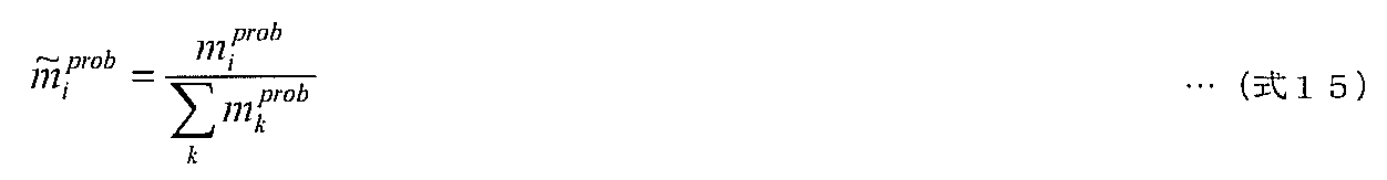
図17は、本発明の実施の形態2におけるバスシステム監視装置(アービタ)の制御対象の一例としての、映像符号化SoCの構成を示すブロック図である。 (Embodiment 2)
FIG. 17 is a block diagram illustrating a configuration of a video encoding SoC as an example of a control target of the bus system monitoring apparatus (arbiter) according to the second embodiment of the present invention.
発生データ量取得部206は、監視対象特定部113によって選択されたビデオデータ送信経路上の信号処理プロセッサDSP2、DSP3、DSP4、DSP5に対して、発生データ量情報の取得を行う。 (Generated data amount acquisition unit 206)
The generated data

図22は、発生データ量記録部207によって実行される処理の一例を示すフローチャートである。 (Generated data amount recording unit 207)
FIG. 22 is a flowchart illustrating an example of processing executed by the generated data


デシメーション処理部208は、発生データ量情報テーブルを基にしてVBUS2にデータ転送するデータ量を適正な値に調節する。発生データ量の制御は、入力フレームバッファから読み込む映像信号に対するデシメーションフィルタの出力解像度の調整によって行ってもよい。 (Decimation processing unit 208)
The
図24は、活性度算出部209によって実行される処理の一例を示すフローチャートである。図24に示されるように、活性度算出部209の処理(S90~S98)は、活性度算出部109の処理(図12のS40~S49を参照)と比べて、リンクRTTliの正規化値の代わりに発生データ量Piの正規化値を用いる点で相違する。 (Activity calculation unit 209)
FIG. 24 is a flowchart illustrating an example of processing executed by the activity calculation unit 209. As shown in FIG. 24, the processing of the activity calculation unit 209 (S90 ~ S98), compared with the process of the activity calculation unit 109 (see S40 ~ S49 of FIG. 12), the normalized value of the link RTTl i to different in using a normalized value of the generated data amount P i instead of.

半導体プロセッサの省電力化は、プロセスルールの微細化による高集積化によって進められてきた。しかしながら、現在主流となっているような微細なプロセスルールにおいては、トランジスタ回路におけるリーク電流の増大等により、さらなる高集積化と消費電力の低減が両立するようなスケーリングが困難となっている。 (Embodiment 3)
Power saving of semiconductor processors has been promoted by high integration by miniaturizing process rules. However, in a fine process rule which is currently mainstream, scaling that makes it possible to achieve both higher integration and lower power consumption is difficult due to an increase in leakage current in a transistor circuit.
伝送状態取得部106は、監視対象特定部113によって特定された監視対象となるNoCルータから、監視対象伝送状態情報を取得する。NoCルータにおけるフリットの平均滞在時間Rは、監視対象伝送状態情報の一例として考えられるため、本実施の形態では、平均滞在時間を用いて説明を行う。監視対象伝送状態情報には、NoCルータの負荷状況を反映する指標であれば、平均滞在時間以外の指標を用いてもよい。 (Transmission state acquisition unit 106)
The transmission
伝送状態取得部106によって、各送信経路上の各NoCルータにおけるフリットの平均滞在時間が収集される。図27において、コアプロセッサCP00から、NoCルータR00、R01、R02、R03、R13、R23、R33を経てCP33に至る経路上のNoCルータの平均滞留時間の最大値をR1とし、コアプロセッサCP00から、NoCルータR00、R10、R20、R30、R31、R32、R33を経てCP33に至る経路上のNoCルータの平均滞留時間の最大値をR2とする。このとき、R1およびR2は、式20および式21のように表される。 (Transmitter 108)
The transmission

一様分布やガウス分布に従う疑似乱数の生成は、ゲート数に厳しい制約が課される半導体やメモリリソースの少ないネットワーク用途の組込プロセッサにおいては、実装が困難な場合がある。 (Selection probability generator 112)
The generation of pseudo-random numbers according to a uniform distribution or a Gaussian distribution may be difficult to implement in an embedded processor for a network application having a small number of gates and a semiconductor or a memory resource.
監視対象特定部113は、監視対象のNoCルータを特定する際に、活性度算出部109が予め定められた閾値より低い活性度を出力している確率的動作が支配的な状況下では、選択確率生成部112より入力された数値に対応付けられたNoCルータを監視対象として特定する。すなわち、選択確率生成部が記憶している数値リストの順番に従って、監視対象のNoCルータが一様に選択される。 (Monitoring target specifying unit 113)
When the monitoring
図31に、電灯線を用いた業務用のVOD(Video-on-Demand)システムの構成図を示す。 (Embodiment 4)
FIG. 31 shows a configuration diagram of a business VOD (Video-on-Demand) system using a power line.
図33に、VODサーバ511から視聴用モニタ517への経路上に存在するPLCモデム505、506、507の24時間分の伝送状態の変動の模様を示す。 (Monitoring frequency recording unit 111)
FIG. 33 shows a change pattern of the transmission state for 24 hours of the PLC modems 505, 506, and 507 existing on the path from the
監視頻度更新部110は、PLCモデムの組に対する監視頻度miの値を、各PLCモデムの監視頻度miと同様の方法で更新し正規化する。 (Monitoring frequency update unit 110)
Monitoring
伝送状態取得部106は、PLCモデムの組に対する伝送状態取得時には、対応する複数のPLCモデムに対して、図6、図7に示した方法と同様の方法を用いて、伝送状態を取得する。 (Transmission state acquisition unit 106)
When acquiring the transmission status for the set of PLC modems, the transmission
101~104 中継器
105 受信機
106 伝送状態取得部
107 伝送状態記録部
108 送信部
109 活性度算出部
110 監視頻度更新部
111 監視頻度記録部
112 選択確率生成部
113 監視対象特定部
200 バスシステム監視装置
206 発生データ量取得部
207 発生データ量記録部
208 デシメーション処理部
209 活性度算出部
331 入力バッファ
332 滞留カウンタ
333 クロスバースイッチ
500 配電盤
501~507 PLCモデム
511 VODサーバ
512~517 視聴用モニタ DESCRIPTION OF
Claims (13)
- 複数の中継器を介してデータを伝送するネットワークを監視するネットワーク監視装置であって、
前記各中継器の伝送状態の監視頻度を記録している監視頻度記録部と、
前記各中継器について所定の確率値である選択確率情報を生成する選択確率生成部と、
前記監視頻度と前記選択確率情報とに従って、前記複数の中継器の中から伝送状態の監視の対象となる中継器を特定する監視対象特定部と、
前記監視対象特定部によって特定された中継器における伝送状態を示す伝送状態情報を取得する伝送状態取得部と、
前記伝送状態情報を記録する伝送状態記録部と、
前記伝送状態情報から、前記各中継器の伝送状態の監視の正確性を表す活性度を算出する活性度算出部と、
前記活性度に基づき、前記監視頻度記録部に記録されている監視頻度を更新する監視頻度更新部と
を備えるネットワーク監視装置。 A network monitoring device for monitoring a network that transmits data via a plurality of repeaters,
A monitoring frequency recording unit that records the monitoring frequency of the transmission state of each repeater;
A selection probability generation unit that generates selection probability information that is a predetermined probability value for each of the repeaters;
According to the monitoring frequency and the selection probability information, a monitoring target specifying unit that specifies a relay that is a monitoring target of a transmission state from the plurality of relays;
A transmission state acquisition unit for acquiring transmission state information indicating a transmission state in the repeater specified by the monitoring target specifying unit;
A transmission state recording unit for recording the transmission state information;
From the transmission status information, an activity calculation unit that calculates the activity indicating the accuracy of monitoring the transmission status of each repeater;
A network monitoring apparatus comprising: a monitoring frequency update unit that updates a monitoring frequency recorded in the monitoring frequency recording unit based on the activity. - 前記活性度算出部は、前記各中継器の伝送状態と監視頻度との相関によって前記活性度を算出する
請求項1に記載のネットワーク監視装置。 The network monitoring apparatus according to claim 1, wherein the activity calculation unit calculates the activity based on a correlation between a transmission state of each repeater and a monitoring frequency. - 前記伝送状態記録部は、各中継器iの往復伝搬遅延時間liを、前記伝送状態情報として記録しており、
前記活性度算出部は、前記往復伝搬遅延時間liが大きい中継器ほど当該中継器の監視頻度miが高いという傾向の強さを表す相関値αを算出し、
前記監視頻度更新部は、前記相関値αが小さいほど、各中継器の監視頻度miのうちの最大値と他の値との差が小さくなるように、各監視頻度miを更新し、
前記選択確率生成部は、各中継器について、前記差の収束値に応じて決定される範囲内の乱数値である確率値ηiを生成し、
前記監視対象特定部は、監視頻度miと確率値ηiとを加算した各中継器の監視頻度によって表される確率分布に従って、伝送状態の監視の対象となる中継器を、確率的挙動を持って特定する
請求項2に記載のネットワーク監視装置。 The transmission state recording unit records the round trip propagation delay time l i of each repeater i as the transmission state information,
The activity calculation unit calculates a correlation value α representing the propagation delay l i is greater repeater as the strength of the trend of the monitoring frequency m i of the repeater is high,
The monitoring frequency updating unit, the higher the correlation value α is small, so that the difference between the maximum value and the other values of the monitoring frequency m i of each repeater is reduced, and updates the respective monitoring frequency m i,
The selection probability generation unit generates a probability value η i that is a random value within a range determined according to the convergence value of the difference for each repeater,
The monitoring target specifying unit determines a repeater to be a target of transmission state monitoring according to a probability distribution represented by the monitoring frequency of each repeater obtained by adding the monitoring frequency m i and the probability value η i. The network monitoring apparatus according to claim 2, wherein the network monitoring apparatus is specified. - 複数の信号処理部を接続し、かつ前記複数の信号処理部で加工されるデータを伝送するバスシステムを監視するバスシステム監視装置であって、
各信号処理部のデータ発生状況の監視頻度を記録している監視頻度記録部と、
前記各信号処理部について所定の確率値である選択確率情報を生成する選択確率生成部と、
前記監視頻度と前記選択確率情報とに従って、データ発生状況の監視の対象となる信号処理部を特定する監視対象特定部と、
前記監視対象特定部によって特定された信号処理部におけるデータ発生状況を示す発生データ量情報を取得する発生データ量取得部と、
前記発生データ量情報を記録する発生データ量記録部と、
前記発生データ量情報から、前記各信号処理部のデータ発生状況の監視の正確性を表す活性度を算出する活性度算出部と、
前記活性度に基づき、前記監視頻度記録部に記録されている監視頻度を更新する監視頻度更新部と
を備えるバスシステム監視装置。 A bus system monitoring apparatus that connects a plurality of signal processing units and monitors a bus system that transmits data processed by the plurality of signal processing units,
A monitoring frequency recording unit that records the monitoring frequency of the data generation status of each signal processing unit;
A selection probability generation unit that generates selection probability information that is a predetermined probability value for each of the signal processing units;
In accordance with the monitoring frequency and the selection probability information, a monitoring target specifying unit that specifies a signal processing unit to be monitored for data occurrence status;
A generated data amount acquisition unit for acquiring generated data amount information indicating a data generation state in the signal processing unit specified by the monitoring target specifying unit;
A generated data amount recording unit for recording the generated data amount information;
From the generated data amount information, an activity calculating unit that calculates an activity indicating the accuracy of monitoring the data generation status of each signal processing unit;
A bus system monitoring apparatus comprising: a monitoring frequency updating unit that updates a monitoring frequency recorded in the monitoring frequency recording unit based on the activity. - 前記活性度算出部は、前記各信号処理部のデータ発生状況と監視頻度との相関によって前記活性度を算出する
請求項4に記載のバスシステム監視装置。 The bus system monitoring apparatus according to claim 4, wherein the activity calculation unit calculates the activity based on a correlation between a data generation status of each signal processing unit and a monitoring frequency. - 前記伝送状態記録部は、各信号処理部iにおける発生データ量piを記録しており、
前記活性度算出部は、前記発生データ量piが大きい信号処理部ほど当該信号処理部の監視頻度miが高いという傾向の強さを表す相関値αを算出し、
前記監視頻度更新部は、前記相関値αが小さいほど、各信号処理部の監視頻度miのうちの最大値と他の値との差が小さくなるように、各監視頻度miを更新し、
前記選択確率生成部は、各信号処理部について、前記差の収束値に応じて決定される範囲内の乱数値である確率値ηiを生成し、
前記監視対象特定部は、監視頻度miと確率値ηiとを加算した各信号処理部の監視頻度によって表される確率分布に従って、データ発生状況の監視の対象となる信号処理部を、確率的挙動を持って特定する
請求項5に記載のバスシステム監視装置。 The transmission state recording unit records the generated data amount p i in each signal processing unit i,
The activity calculation unit calculates a correlation value α representing the generated data amount p i is larger signal processing unit as the strength of the trend of the monitoring frequency m i of the signal processing unit is high,
The monitoring frequency updating unit, the higher the correlation value α is small, so that the difference between the maximum value and the other values of the monitoring frequency m i of each signal processing unit is reduced, and updates the respective monitoring frequency m i ,
The selection probability generation unit generates, for each signal processing unit, a probability value η i that is a random value within a range determined according to the convergence value of the difference,
The monitoring target specifying unit determines a signal processing unit to be monitored for data generation status according to a probability distribution represented by the monitoring frequency of each signal processing unit obtained by adding the monitoring frequency mi and the probability value η i. The bus system monitoring device according to claim 5, wherein the bus system monitoring device is specified with a specific behavior. - 複数の中継器を介してデータを伝送するネットワークを監視するネットワーク監視装置において行われるネットワーク監視方法であって、
前記ネットワーク監視装置は、監視頻度記録部と、選択確率生成部と、監視対象特定部と、伝送状態取得部と、伝送状態記録部と、活性度算出部と、監視頻度更新部とを備え、
前記監視頻度記録部は、前記各中継器の伝送状態の監視頻度を記録しており、
前記ネットワーク監視方法は、
前記選択確率生成部で、前記各中継器について所定の確率値である選択確率情報を生成するステップと、
前記監視対象特定部で、前記監視頻度と前記選択確率情報とに従って、前記複数の中継器の中から伝送状態の監視の対象となる中継器を特定するステップと、
前記伝送状態取得部で、前記監視対象特定ステップによって特定された中継器における伝送状態を示す伝送状態情報を取得するステップと、
前記伝送状態記録部で、前記伝送状態情報を記録するステップと、
前記活性度算出部で、前記伝送状態情報から、前記各中継器の伝送状態の監視の正確性を表す活性度を算出するステップと、
前記監視頻度更新部で、前記活性度に基づき、前記監視頻度記録部に記録されている監視頻度を更新するステップと
を含むことを特徴とするネットワーク監視方法。 A network monitoring method performed in a network monitoring device that monitors a network that transmits data via a plurality of repeaters,
The network monitoring device includes a monitoring frequency recording unit, a selection probability generation unit, a monitoring target specifying unit, a transmission state acquisition unit, a transmission state recording unit, an activity calculation unit, and a monitoring frequency update unit,
The monitoring frequency recording unit records the monitoring frequency of the transmission state of each repeater,
The network monitoring method includes:
In the selection probability generation unit, generating selection probability information that is a predetermined probability value for each repeater;
In the monitoring target specifying unit, according to the monitoring frequency and the selection probability information, specifying a repeater to be monitored for transmission status from the plurality of repeaters;
In the transmission state acquisition unit, acquiring transmission state information indicating a transmission state in the repeater specified by the monitoring target specifying step;
Recording the transmission state information in the transmission state recording unit;
In the activity level calculation unit, from the transmission status information, calculating an activity level indicating the accuracy of monitoring the transmission status of each repeater;
Updating the monitoring frequency recorded in the monitoring frequency recording unit based on the activity level in the monitoring frequency updating unit. - 複数の信号処理部を接続し、かつ前記複数の信号処理部で加工されるデータを伝送するバスシステムを監視するバスシステム監視装置において行われるバスシステム監視方法であって、
前記バスシステム監視装置は、監視頻度記録部と、選択確率生成部と、監視対象特定部と、発生データ量取得部と、発生データ量記録部と、活性度算出部と、監視頻度更新部とを備え、
前記監視頻度記録部は、前記各信号処理部における発生データ量の監視頻度を記録しており、
前記バスシステム監視方法は、
前記選択確率生成部で、前記各信号処理部について所定の確率値である選択確率情報を生成するステップと、
前記監視対象特定部で、前記監視頻度と前記選択確率情報とに従って、データ発生状況の監視の対象となる信号処理部を特定するステップと、
前記発生データ量取得部で、前記監視対象特定ステップによって特定された信号処理部におけるデータ発生状況を示す発生データ量情報を取得するステップと、
前記発生データ量記録部で、前記発生データ量情報を記録するステップと、
前記活性度算出部で、前記発生データ量情報から、前記各信号処理部のデータ発生状況の監視の正確性を表す活性度を算出するステップと、
前記監視頻度更新部で、前記活性度に基づき、前記監視頻度記録部に記録されている監視頻度を更新するステップと
を含むことを特徴とするバスシステム監視方法。 A bus system monitoring method performed in a bus system monitoring device that monitors a bus system that connects a plurality of signal processing units and transmits data processed by the plurality of signal processing units,
The bus system monitoring device includes a monitoring frequency recording unit, a selection probability generation unit, a monitoring target specifying unit, a generated data amount acquisition unit, a generated data amount recording unit, an activity calculation unit, and a monitoring frequency update unit. With
The monitoring frequency recording unit records the monitoring frequency of the generated data amount in each signal processing unit,
The bus system monitoring method includes:
Generating selection probability information that is a predetermined probability value for each of the signal processing units in the selection probability generation unit;
In the monitoring target specifying unit, according to the monitoring frequency and the selection probability information, specifying a signal processing unit to be monitored for data generation status;
In the generated data amount acquisition unit, acquiring generated data amount information indicating a data generation status in the signal processing unit specified by the monitoring target specifying step;
Recording the generated data amount information in the generated data amount recording unit;
A step of calculating an activity level representing the accuracy of monitoring the data generation status of each signal processing unit from the generated data amount information in the activity level calculation unit;
And updating the monitoring frequency recorded in the monitoring frequency recording unit based on the activity level in the monitoring frequency updating unit. - 請求項7に記載のネットワーク監視方法に含まれるステップを、コンピュータに実行させることを特徴とするプログラム。 A program that causes a computer to execute the steps included in the network monitoring method according to claim 7.
- 請求項8に記載のバスシステム監視方法に含まれるステップを、コンピュータに実行させることを特徴とするプログラム。 A program that causes a computer to execute the steps included in the bus system monitoring method according to claim 8.
- 中継器を介してコアが相互に接続された半導体上で複数の送信経路の伝送状態を監視しながらバス上でデータを転送するバスシステム監視装置であって、
各中継器の監視頻度を記録している監視頻度記録部と、
前記各中継器について所定の確率値である選択確率情報を生成する選択確率生成部と、
前記監視頻度と前記選択確率情報とに従って、監視の対象となる中継器を特定する監視対象特定部と、
前記監視対象特定部によって特定された中継器における伝送状態を示す伝送状態情報を取得する伝送状態取得部と、
前記伝送状態情報を記録する伝送状態記録部と、
前記伝送状態情報から、前記各中継器の伝送状態の監視の正確性を表す活性度を算出する活性度算出部と、
前記活性度に基づき、前記監視頻度記録部に記録されている監視頻度を更新する監視頻度更新部と
を備えるバスシステム監視装置。 A bus system monitoring device for transferring data on a bus while monitoring transmission states of a plurality of transmission paths on a semiconductor in which cores are connected to each other via a repeater,
A monitoring frequency recording unit that records the monitoring frequency of each repeater;
A selection probability generation unit that generates selection probability information that is a predetermined probability value for each of the repeaters;
According to the monitoring frequency and the selection probability information, a monitoring target specifying unit that specifies a repeater to be monitored;
A transmission state acquisition unit for acquiring transmission state information indicating a transmission state in the repeater specified by the monitoring target specifying unit;
A transmission state recording unit for recording the transmission state information;
From the transmission status information, an activity calculation unit that calculates the activity indicating the accuracy of monitoring the transmission status of each repeater;
A bus system monitoring apparatus comprising: a monitoring frequency updating unit that updates a monitoring frequency recorded in the monitoring frequency recording unit based on the activity. - 前記選択確率生成部は、前記活性度算出部が算出した前記活性度の値が予め定められた閾値より低い場合には、予め記録された一連の数値列のリストから読み出した数値を、前記選択確率情報として前記監視対象特定部に提供し、
前記監視対象特定部は、前記選択確率生成部によって提供された数値に対応付けられた中継器を監視対象として特定する
請求項11に記載のバスシステム監視装置。 The selection probability generation unit, when the value of the activity calculated by the activity calculation unit is lower than a predetermined threshold, selects a numerical value read from a list of a series of numerical values recorded in advance. Providing the monitoring target specifying unit as probability information,
The bus system monitoring apparatus according to claim 11, wherein the monitoring target specifying unit specifies a repeater associated with the numerical value provided by the selection probability generation unit as a monitoring target. - 前記監視頻度更新部は、複数の中継器の組に対する監視頻度を更新する
請求項1に記載のネットワーク監視装置。 The network monitoring apparatus according to claim 1, wherein the monitoring frequency update unit updates a monitoring frequency for a set of a plurality of repeaters.
Priority Applications (4)
| Application Number | Priority Date | Filing Date | Title |
|---|---|---|---|
| EP09762280.7A EP2288086B1 (en) | 2008-06-12 | 2009-06-12 | Network monitoring device, bus system monitoring device, method and program |
| CN2009801153196A CN102017548B (en) | 2008-06-12 | 2009-06-12 | Network monitoring device, bus system monitoring device, method and program |
| US12/989,808 US8352594B2 (en) | 2008-06-12 | 2009-06-12 | Network monitoring device, bus system monitoring device, method and program |
| JP2010516764A JP4607254B2 (en) | 2008-06-12 | 2009-06-12 | Network monitoring device, bus system monitoring device, method, and program |
Applications Claiming Priority (4)
| Application Number | Priority Date | Filing Date | Title |
|---|---|---|---|
| JP2008-154031 | 2008-06-12 | ||
| JP2008154031 | 2008-06-12 | ||
| JP2009-021006 | 2009-01-30 | ||
| JP2009021006 | 2009-01-30 |
Publications (1)
| Publication Number | Publication Date |
|---|---|
| WO2009150849A1 true WO2009150849A1 (en) | 2009-12-17 |
Family
ID=41416562
Family Applications (1)
| Application Number | Title | Priority Date | Filing Date |
|---|---|---|---|
| PCT/JP2009/002660 WO2009150849A1 (en) | 2008-06-12 | 2009-06-12 | Network monitoring device, bus system monitoring device, method and program |
Country Status (5)
| Country | Link |
|---|---|
| US (1) | US8352594B2 (en) |
| EP (1) | EP2288086B1 (en) |
| JP (1) | JP4607254B2 (en) |
| CN (1) | CN102017548B (en) |
| WO (1) | WO2009150849A1 (en) |
Cited By (8)
| Publication number | Priority date | Publication date | Assignee | Title |
|---|---|---|---|---|
| WO2011089899A1 (en) * | 2010-01-25 | 2011-07-28 | パナソニック株式会社 | Semiconductor system, relay apparatus, and chip circuit |
| WO2011142087A1 (en) * | 2010-05-12 | 2011-11-17 | パナソニック株式会社 | Router and chip circuit |
| WO2011148583A1 (en) * | 2010-05-27 | 2011-12-01 | パナソニック株式会社 | Bus control device and control device for outputting instructions to the bus control device |
| CN102547206A (en) * | 2010-12-30 | 2012-07-04 | 中国移动通信集团公司 | Method and device for determining video transmission parameter during video communication |
| JP2012213124A (en) * | 2011-03-31 | 2012-11-01 | Secom Co Ltd | Monitoring device and program |
| JP2013532453A (en) * | 2010-07-09 | 2013-08-15 | クアルコム,インコーポレイテッド | Techniques using frits for clock gating |
| JP2014216991A (en) * | 2013-04-30 | 2014-11-17 | 株式会社日立製作所 | Analysis server and analysis method |
| EP2400754A3 (en) * | 2010-06-24 | 2016-05-18 | Sony Corporation | Connection setting method, camera system, and recording medium |
Families Citing this family (115)
| Publication number | Priority date | Publication date | Assignee | Title |
|---|---|---|---|---|
| US7675854B2 (en) | 2006-02-21 | 2010-03-09 | A10 Networks, Inc. | System and method for an adaptive TCP SYN cookie with time validation |
| US8584199B1 (en) | 2006-10-17 | 2013-11-12 | A10 Networks, Inc. | System and method to apply a packet routing policy to an application session |
| US8312507B2 (en) | 2006-10-17 | 2012-11-13 | A10 Networks, Inc. | System and method to apply network traffic policy to an application session |
| US9961094B1 (en) | 2007-07-25 | 2018-05-01 | Xangati, Inc | Symptom detection using behavior probability density, network monitoring of multiple observation value types, and network monitoring using orthogonal profiling dimensions |
| US10992555B2 (en) | 2009-05-29 | 2021-04-27 | Virtual Instruments Worldwide, Inc. | Recording, replay, and sharing of live network monitoring views |
| US9960967B2 (en) | 2009-10-21 | 2018-05-01 | A10 Networks, Inc. | Determining an application delivery server based on geo-location information |
| US9215275B2 (en) | 2010-09-30 | 2015-12-15 | A10 Networks, Inc. | System and method to balance servers based on server load status |
| CN108429800B (en) * | 2010-11-22 | 2020-04-24 | 杭州硕文软件有限公司 | Mobile device |
| US9609052B2 (en) | 2010-12-02 | 2017-03-28 | A10 Networks, Inc. | Distributing application traffic to servers based on dynamic service response time |
| CN102845022B (en) * | 2011-04-20 | 2016-08-10 | 华为技术有限公司 | Transmission quality determining method, device and transmission system |
| US8619846B2 (en) * | 2011-04-21 | 2013-12-31 | Landis+Gyr | Amplitude control in a variable load environment |
| US8897154B2 (en) | 2011-10-24 | 2014-11-25 | A10 Networks, Inc. | Combining stateless and stateful server load balancing |
| US9386088B2 (en) | 2011-11-29 | 2016-07-05 | A10 Networks, Inc. | Accelerating service processing using fast path TCP |
| US9094364B2 (en) | 2011-12-23 | 2015-07-28 | A10 Networks, Inc. | Methods to manage services over a service gateway |
| US10044582B2 (en) | 2012-01-28 | 2018-08-07 | A10 Networks, Inc. | Generating secure name records |
| US8782221B2 (en) | 2012-07-05 | 2014-07-15 | A10 Networks, Inc. | Method to allocate buffer for TCP proxy session based on dynamic network conditions |
| US9647921B2 (en) | 2012-08-07 | 2017-05-09 | Qualcomm Incorporated | Statistics and failure detection in a network on a chip (NoC) network |
| US9244880B2 (en) | 2012-08-30 | 2016-01-26 | Netspeed Systems | Automatic construction of deadlock free interconnects |
| US10021174B2 (en) | 2012-09-25 | 2018-07-10 | A10 Networks, Inc. | Distributing service sessions |
| US9106561B2 (en) | 2012-12-06 | 2015-08-11 | A10 Networks, Inc. | Configuration of a virtual service network |
| US10002141B2 (en) | 2012-09-25 | 2018-06-19 | A10 Networks, Inc. | Distributed database in software driven networks |
| CN108027805B (en) | 2012-09-25 | 2021-12-21 | A10网络股份有限公司 | Load distribution in a data network |
| US9843484B2 (en) | 2012-09-25 | 2017-12-12 | A10 Networks, Inc. | Graceful scaling in software driven networks |
| US8885510B2 (en) | 2012-10-09 | 2014-11-11 | Netspeed Systems | Heterogeneous channel capacities in an interconnect |
| US8601423B1 (en) | 2012-10-23 | 2013-12-03 | Netspeed Systems | Asymmetric mesh NoC topologies |
| US9338225B2 (en) | 2012-12-06 | 2016-05-10 | A10 Networks, Inc. | Forwarding policies on a virtual service network |
| US9774498B2 (en) | 2012-12-21 | 2017-09-26 | Netspeed Systems | Hierarchical asymmetric mesh with virtual routers |
| US9253085B2 (en) | 2012-12-21 | 2016-02-02 | Netspeed Systems | Hierarchical asymmetric mesh with virtual routers |
| US9185026B2 (en) | 2012-12-21 | 2015-11-10 | Netspeed Systems | Tagging and synchronization for fairness in NOC interconnects |
| US9007920B2 (en) | 2013-01-18 | 2015-04-14 | Netspeed Systems | QoS in heterogeneous NoC by assigning weights to NoC node channels and using weighted arbitration at NoC nodes |
| US9009648B2 (en) | 2013-01-18 | 2015-04-14 | Netspeed Systems | Automatic deadlock detection and avoidance in a system interconnect by capturing internal dependencies of IP cores using high level specification |
| US9531846B2 (en) | 2013-01-23 | 2016-12-27 | A10 Networks, Inc. | Reducing buffer usage for TCP proxy session based on delayed acknowledgement |
| US9130856B2 (en) | 2013-01-28 | 2015-09-08 | Netspeed Systems | Creating multiple NoC layers for isolation or avoiding NoC traffic congestion |
| US9900252B2 (en) | 2013-03-08 | 2018-02-20 | A10 Networks, Inc. | Application delivery controller and global server load balancer |
| US8934377B2 (en) | 2013-03-11 | 2015-01-13 | Netspeed Systems | Reconfigurable NoC for customizing traffic and optimizing performance after NoC synthesis |
| US9992107B2 (en) | 2013-03-15 | 2018-06-05 | A10 Networks, Inc. | Processing data packets using a policy based network path |
| US9160627B2 (en) | 2013-04-04 | 2015-10-13 | Netspeed Systems | Multiple heterogeneous NoC layers |
| US9571402B2 (en) | 2013-05-03 | 2017-02-14 | Netspeed Systems | Congestion control and QoS in NoC by regulating the injection traffic |
| US10038693B2 (en) | 2013-05-03 | 2018-07-31 | A10 Networks, Inc. | Facilitating secure network traffic by an application delivery controller |
| US10027761B2 (en) | 2013-05-03 | 2018-07-17 | A10 Networks, Inc. | Facilitating a secure 3 party network session by a network device |
| US9185023B2 (en) | 2013-05-03 | 2015-11-10 | Netspeed Systems | Heterogeneous SoC IP core placement in an interconnect to optimize latency and interconnect performance |
| US10027433B2 (en) | 2013-06-19 | 2018-07-17 | Netspeed Systems | Multiple clock domains in NoC |
| US9781043B2 (en) | 2013-07-15 | 2017-10-03 | Netspeed Systems | Identification of internal dependencies within system components for evaluating potential protocol level deadlocks |
| US9471726B2 (en) | 2013-07-25 | 2016-10-18 | Netspeed Systems | System level simulation in network on chip architecture |
| US9054977B2 (en) | 2013-08-05 | 2015-06-09 | Netspeed Systems | Automatic NoC topology generation |
| US9473388B2 (en) | 2013-08-07 | 2016-10-18 | Netspeed Systems | Supporting multicast in NOC interconnect |
| US9223711B2 (en) | 2013-08-13 | 2015-12-29 | Netspeed Systems | Combining associativity and cuckoo hashing |
| US9294354B2 (en) | 2013-10-24 | 2016-03-22 | Netspeed Systems | Using multiple traffic profiles to design a network on chip |
| US9830265B2 (en) | 2013-11-20 | 2017-11-28 | Netspeed Systems, Inc. | Reuse of directory entries for holding state information through use of multiple formats |
| US10230770B2 (en) | 2013-12-02 | 2019-03-12 | A10 Networks, Inc. | Network proxy layer for policy-based application proxies |
| US9158882B2 (en) | 2013-12-19 | 2015-10-13 | Netspeed Systems | Automatic pipelining of NoC channels to meet timing and/or performance |
| US9699079B2 (en) | 2013-12-30 | 2017-07-04 | Netspeed Systems | Streaming bridge design with host interfaces and network on chip (NoC) layers |
| US9473415B2 (en) | 2014-02-20 | 2016-10-18 | Netspeed Systems | QoS in a system with end-to-end flow control and QoS aware buffer allocation |
| US9942152B2 (en) | 2014-03-25 | 2018-04-10 | A10 Networks, Inc. | Forwarding data packets using a service-based forwarding policy |
| US10020979B1 (en) | 2014-03-25 | 2018-07-10 | A10 Networks, Inc. | Allocating resources in multi-core computing environments |
| US9942162B2 (en) | 2014-03-31 | 2018-04-10 | A10 Networks, Inc. | Active application response delay time |
| US9319232B2 (en) | 2014-04-04 | 2016-04-19 | Netspeed Systems | Integrated NoC for performing data communication and NoC functions |
| US9762474B2 (en) | 2014-04-07 | 2017-09-12 | Netspeed Systems | Systems and methods for selecting a router to connect a bridge in the network on chip (NoC) |
| US9860818B2 (en) * | 2014-04-17 | 2018-01-02 | T-Mobile Usa, Inc. | Resource allocation for self-organizing networks |
| US9806943B2 (en) | 2014-04-24 | 2017-10-31 | A10 Networks, Inc. | Enabling planned upgrade/downgrade of network devices without impacting network sessions |
| DK2943011T3 (en) * | 2014-05-08 | 2019-07-22 | Icomera Ab | Wireless communication system for moving vessels |
| US9244845B2 (en) | 2014-05-12 | 2016-01-26 | Netspeed Systems | System and method for improving snoop performance |
| US9906422B2 (en) | 2014-05-16 | 2018-02-27 | A10 Networks, Inc. | Distributed system to determine a server's health |
| US9986061B2 (en) | 2014-06-03 | 2018-05-29 | A10 Networks, Inc. | Programming a data network device using user defined scripts |
| US10129122B2 (en) | 2014-06-03 | 2018-11-13 | A10 Networks, Inc. | User defined objects for network devices |
| US9992229B2 (en) | 2014-06-03 | 2018-06-05 | A10 Networks, Inc. | Programming a data network device using user defined scripts with licenses |
| US9473359B2 (en) | 2014-06-06 | 2016-10-18 | Netspeed Systems | Transactional traffic specification for network-on-chip design |
| US9535848B2 (en) | 2014-06-18 | 2017-01-03 | Netspeed Systems | Using cuckoo movement for improved cache coherency |
| US9577949B2 (en) | 2014-08-11 | 2017-02-21 | Cisco Technology, Inc. | Maintaining named data networking (NDN) flow balance with highly variable data object sizes |
| US9716638B1 (en) * | 2015-08-24 | 2017-07-25 | Virtual Instruments | Push pull data collection |
| US10250470B1 (en) | 2014-08-24 | 2019-04-02 | Virtual Instruments Worldwide | Push pull data collection |
| US10009237B1 (en) * | 2014-08-24 | 2018-06-26 | Virtual Instruments Worldwide | Cross silo time stiching |
| US10528682B2 (en) | 2014-09-04 | 2020-01-07 | Netspeed Systems | Automatic performance characterization of a network-on-chip (NOC) interconnect |
| US9742630B2 (en) | 2014-09-22 | 2017-08-22 | Netspeed Systems | Configurable router for a network on chip (NoC) |
| US9477280B1 (en) | 2014-09-24 | 2016-10-25 | Netspeed Systems | Specification for automatic power management of network-on-chip and system-on-chip |
| US10042404B2 (en) | 2014-09-26 | 2018-08-07 | Netspeed Systems | Automatic generation of power management sequence in a SoC or NoC |
| US9571341B1 (en) | 2014-10-01 | 2017-02-14 | Netspeed Systems | Clock gating for system-on-chip elements |
| KR101619623B1 (en) * | 2014-10-20 | 2016-05-10 | 현대자동차주식회사 | System and method for reprogramming of vehicle controller |
| US9529400B1 (en) | 2014-10-29 | 2016-12-27 | Netspeed Systems | Automatic power domain and voltage domain assignment to system-on-chip agents and network-on-chip elements |
| US9660942B2 (en) | 2015-02-03 | 2017-05-23 | Netspeed Systems | Automatic buffer sizing for optimal network-on-chip design |
| US9444702B1 (en) | 2015-02-06 | 2016-09-13 | Netspeed Systems | System and method for visualization of NoC performance based on simulation output |
| US9568970B1 (en) | 2015-02-12 | 2017-02-14 | Netspeed Systems, Inc. | Hardware and software enabled implementation of power profile management instructions in system on chip |
| US9928204B2 (en) | 2015-02-12 | 2018-03-27 | Netspeed Systems, Inc. | Transaction expansion for NoC simulation and NoC design |
| US10348563B2 (en) | 2015-02-18 | 2019-07-09 | Netspeed Systems, Inc. | System-on-chip (SoC) optimization through transformation and generation of a network-on-chip (NoC) topology |
| US10050843B2 (en) | 2015-02-18 | 2018-08-14 | Netspeed Systems | Generation of network-on-chip layout based on user specified topological constraints |
| US9825809B2 (en) | 2015-05-29 | 2017-11-21 | Netspeed Systems | Dynamically configuring store-and-forward channels and cut-through channels in a network-on-chip |
| US9864728B2 (en) | 2015-05-29 | 2018-01-09 | Netspeed Systems, Inc. | Automatic generation of physically aware aggregation/distribution networks |
| US10218580B2 (en) | 2015-06-18 | 2019-02-26 | Netspeed Systems | Generating physically aware network-on-chip design from a physical system-on-chip specification |
| US10581976B2 (en) | 2015-08-12 | 2020-03-03 | A10 Networks, Inc. | Transmission control of protocol state exchange for dynamic stateful service insertion |
| US10243791B2 (en) | 2015-08-13 | 2019-03-26 | A10 Networks, Inc. | Automated adjustment of subscriber policies |
| US10348549B1 (en) | 2015-08-24 | 2019-07-09 | Virtual Instruments Worldwide | Storm detection, analysis, remediation, and other network behavior |
| US9935858B1 (en) | 2015-08-24 | 2018-04-03 | Xangati, Inc | Enhanched flow processing |
| US20170126550A1 (en) * | 2015-10-29 | 2017-05-04 | Ca, Inc. | Selecting a flow data source |
| US10318288B2 (en) | 2016-01-13 | 2019-06-11 | A10 Networks, Inc. | System and method to process a chain of network applications |
| US10452124B2 (en) | 2016-09-12 | 2019-10-22 | Netspeed Systems, Inc. | Systems and methods for facilitating low power on a network-on-chip |
| US20180159786A1 (en) | 2016-12-02 | 2018-06-07 | Netspeed Systems, Inc. | Interface virtualization and fast path for network on chip |
| US10313269B2 (en) | 2016-12-26 | 2019-06-04 | Netspeed Systems, Inc. | System and method for network on chip construction through machine learning |
| US10063496B2 (en) | 2017-01-10 | 2018-08-28 | Netspeed Systems Inc. | Buffer sizing of a NoC through machine learning |
| US10389835B2 (en) | 2017-01-10 | 2019-08-20 | A10 Networks, Inc. | Application aware systems and methods to process user loadable network applications |
| US10084725B2 (en) | 2017-01-11 | 2018-09-25 | Netspeed Systems, Inc. | Extracting features from a NoC for machine learning construction |
| US10469337B2 (en) | 2017-02-01 | 2019-11-05 | Netspeed Systems, Inc. | Cost management against requirements for the generation of a NoC |
| US10298485B2 (en) | 2017-02-06 | 2019-05-21 | Netspeed Systems, Inc. | Systems and methods for NoC construction |
| CN107438192A (en) * | 2017-07-26 | 2017-12-05 | 武汉烽火众智数字技术有限责任公司 | The synchronous method of audio and video playing and related system and multimedia play terminal |
| JP6943191B2 (en) * | 2018-01-22 | 2021-09-29 | トヨタ自動車株式会社 | Electronic controls, monitoring methods, and programs |
| US10896476B2 (en) | 2018-02-22 | 2021-01-19 | Netspeed Systems, Inc. | Repository of integration description of hardware intellectual property for NoC construction and SoC integration |
| US10547514B2 (en) | 2018-02-22 | 2020-01-28 | Netspeed Systems, Inc. | Automatic crossbar generation and router connections for network-on-chip (NOC) topology generation |
| US10983910B2 (en) | 2018-02-22 | 2021-04-20 | Netspeed Systems, Inc. | Bandwidth weighting mechanism based network-on-chip (NoC) configuration |
| US11144457B2 (en) | 2018-02-22 | 2021-10-12 | Netspeed Systems, Inc. | Enhanced page locality in network-on-chip (NoC) architectures |
| US11023377B2 (en) | 2018-02-23 | 2021-06-01 | Netspeed Systems, Inc. | Application mapping on hardened network-on-chip (NoC) of field-programmable gate array (FPGA) |
| US11176302B2 (en) | 2018-02-23 | 2021-11-16 | Netspeed Systems, Inc. | System on chip (SoC) builder |
| JP7113282B2 (en) * | 2018-02-28 | 2022-08-05 | パナソニックIpマネジメント株式会社 | Video display system and video display method |
| US11080160B1 (en) | 2019-01-29 | 2021-08-03 | Virtual Instruments Worldwide, Inc. | Self-learning and best-practice profiling and alerting with relative and absolute capacity |
| US10860762B2 (en) | 2019-07-11 | 2020-12-08 | Intel Corpration | Subsystem-based SoC integration |
| RU200168U1 (en) * | 2020-03-03 | 2020-10-08 | Общество с ограниченной ответственностью "НПФ Мультиобработка" | HIGH-FREQUENCY COMMUNICATION DEVICE FOR ELECTRIC POWER LINES |
| CN115150339A (en) * | 2021-03-31 | 2022-10-04 | 瑞昱半导体股份有限公司 | Delay adjustment method and data stream processing device |
Citations (4)
| Publication number | Priority date | Publication date | Assignee | Title |
|---|---|---|---|---|
| JP2003249960A (en) | 2002-02-01 | 2003-09-05 | Microsoft Corp | Peer-to-peer method of quality of service probing and analysis and infrastructure employing same |
| JP2004134966A (en) * | 2002-10-09 | 2004-04-30 | Nec Corp | Apparatus and method for fault detection of communication route, and communication route selecting apparatus |
| JP3662907B2 (en) | 2000-09-22 | 2005-06-22 | 松下電器産業株式会社 | Data transmission / reception method, transmission apparatus, reception apparatus, transmission / reception system, and program |
| JP2005318222A (en) * | 2004-04-28 | 2005-11-10 | Mitsubishi Electric Corp | System and method for packet transmission |
Family Cites Families (19)
| Publication number | Priority date | Publication date | Assignee | Title |
|---|---|---|---|---|
| US5161107A (en) * | 1990-10-25 | 1992-11-03 | Mestech Creation Corporation | Traffic surveillance system |
| US5922051A (en) * | 1997-05-14 | 1999-07-13 | Ncr Corporation | System and method for traffic management in a network management system |
| US6173323B1 (en) * | 1997-12-24 | 2001-01-09 | Lucent Technologies Inc. | Adaptive polling rate algorithm for SNMP-based network monitoring |
| JP3534067B2 (en) | 2000-11-15 | 2004-06-07 | 株式会社日立情報システムズ | Network monitoring device and method, and network monitoring program |
| JP3818901B2 (en) | 2000-12-21 | 2006-09-06 | 富士通株式会社 | Recording medium, network monitoring apparatus, and program |
| US7353269B2 (en) * | 2000-12-21 | 2008-04-01 | Fujitsu Limited | Network monitoring system |
| JP4642353B2 (en) * | 2001-09-12 | 2011-03-02 | 富士通株式会社 | Network monitoring and control device |
| JP2003258903A (en) * | 2002-03-04 | 2003-09-12 | Hitachi Ltd | Communication line monitor system |
| JP3982501B2 (en) * | 2004-01-13 | 2007-09-26 | ソニー株式会社 | Remote imaging device, camera device and option card board |
| WO2006025296A1 (en) * | 2004-08-31 | 2006-03-09 | Nec Corporation | Failure recovery method, network device, and program |
| JP2006287331A (en) * | 2005-03-31 | 2006-10-19 | Fujitsu Ltd | Congestion control network repeating device and method |
| JP4697525B2 (en) * | 2005-04-20 | 2011-06-08 | ソニー株式会社 | Transmission / reception system, transmission apparatus and transmission method, reception apparatus and reception method, and program |
| JP2007328403A (en) * | 2006-06-06 | 2007-12-20 | Matsushita Electric Ind Co Ltd | Bus monitoring circuit and information processing inspection system |
| WO2008035745A1 (en) * | 2006-09-20 | 2008-03-27 | Panasonic Corporation | Monitor system, camera and video image coding method |
| US8799734B2 (en) * | 2007-07-03 | 2014-08-05 | Industrial Technology Research Institute | Transmission control methods and devices for communication systems |
| JP4973734B2 (en) * | 2007-09-26 | 2012-07-11 | 富士通株式会社 | Network monitoring system, route extraction method, program, and computer-readable recording medium recording the program |
| US8103436B1 (en) * | 2007-11-26 | 2012-01-24 | Rhythm Engineering, LLC | External adaptive control systems and methods |
| US8488963B2 (en) * | 2008-06-30 | 2013-07-16 | Infinera Corporation | Link diversity and load balancing across digital and optical express-thru nodes |
| JP5565121B2 (en) * | 2010-06-09 | 2014-08-06 | ソニー株式会社 | COMMUNICATION PROCESSING DEVICE, COMMUNICATION PROCESSING SYSTEM, COMMUNICATION PROCESSING METHOD, AND PROGRAM |
-
2009
- 2009-06-12 US US12/989,808 patent/US8352594B2/en active Active
- 2009-06-12 JP JP2010516764A patent/JP4607254B2/en active Active
- 2009-06-12 WO PCT/JP2009/002660 patent/WO2009150849A1/en active Application Filing
- 2009-06-12 CN CN2009801153196A patent/CN102017548B/en active Active
- 2009-06-12 EP EP09762280.7A patent/EP2288086B1/en active Active
Patent Citations (4)
| Publication number | Priority date | Publication date | Assignee | Title |
|---|---|---|---|---|
| JP3662907B2 (en) | 2000-09-22 | 2005-06-22 | 松下電器産業株式会社 | Data transmission / reception method, transmission apparatus, reception apparatus, transmission / reception system, and program |
| JP2003249960A (en) | 2002-02-01 | 2003-09-05 | Microsoft Corp | Peer-to-peer method of quality of service probing and analysis and infrastructure employing same |
| JP2004134966A (en) * | 2002-10-09 | 2004-04-30 | Nec Corp | Apparatus and method for fault detection of communication route, and communication route selecting apparatus |
| JP2005318222A (en) * | 2004-04-28 | 2005-11-10 | Mitsubishi Electric Corp | System and method for packet transmission |
Non-Patent Citations (1)
| Title |
|---|
| K. LEIBNITZ; N. WAKAMIYA; M. MURATA: "Resilient Multi-path Routing Based on a Biological Attractor Selection Scheme", THE SECOND INTERNATIONAL WORKSHOP ON BIOLOGICALLY INSPIRED APPROACHES TO ADVANCED INFORMATION TECHNOLOGY (BIOADIT 2006), OSAKA, JAPAN, January 2006 (2006-01-01) |
Cited By (18)
| Publication number | Priority date | Publication date | Assignee | Title |
|---|---|---|---|---|
| WO2011089899A1 (en) * | 2010-01-25 | 2011-07-28 | パナソニック株式会社 | Semiconductor system, relay apparatus, and chip circuit |
| JP4820466B2 (en) * | 2010-01-25 | 2011-11-24 | パナソニック株式会社 | Semiconductor system, repeater and chip circuit |
| US9164944B2 (en) | 2010-01-25 | 2015-10-20 | Panasonic Intellectual Property Management Co., Ltd. | Semiconductor system, relay apparatus, and chip circuit |
| CN102474468A (en) * | 2010-01-25 | 2012-05-23 | 松下电器产业株式会社 | Semiconductor system, relay apparatus, and chip circuit |
| WO2011142087A1 (en) * | 2010-05-12 | 2011-11-17 | パナソニック株式会社 | Router and chip circuit |
| US9025457B2 (en) | 2010-05-12 | 2015-05-05 | Panasonic Intellectual Property Management Co., Ltd. | Router and chip circuit |
| CN103109248A (en) * | 2010-05-12 | 2013-05-15 | 松下电器产业株式会社 | Router and chip circuit |
| JP5122025B2 (en) * | 2010-05-12 | 2013-01-16 | パナソニック株式会社 | Repeater and chip circuit |
| CN102893268A (en) * | 2010-05-27 | 2013-01-23 | 松下电器产业株式会社 | Bus control device and control device for outputting instructions to the bus control device |
| JP5276220B2 (en) * | 2010-05-27 | 2013-08-28 | パナソニック株式会社 | Bus control device and control device for outputting instructions to bus control device |
| US9075747B2 (en) | 2010-05-27 | 2015-07-07 | Panasonic Intellectual Property Management Co., Ltd. | Bus controller and control unit that outputs instruction to the bus controller |
| WO2011148583A1 (en) * | 2010-05-27 | 2011-12-01 | パナソニック株式会社 | Bus control device and control device for outputting instructions to the bus control device |
| EP2400754A3 (en) * | 2010-06-24 | 2016-05-18 | Sony Corporation | Connection setting method, camera system, and recording medium |
| JP2013532453A (en) * | 2010-07-09 | 2013-08-15 | クアルコム,インコーポレイテッド | Techniques using frits for clock gating |
| CN102547206B (en) * | 2010-12-30 | 2014-03-26 | 中国移动通信集团公司 | Method and device for determining video transmission parameter during video communication |
| CN102547206A (en) * | 2010-12-30 | 2012-07-04 | 中国移动通信集团公司 | Method and device for determining video transmission parameter during video communication |
| JP2012213124A (en) * | 2011-03-31 | 2012-11-01 | Secom Co Ltd | Monitoring device and program |
| JP2014216991A (en) * | 2013-04-30 | 2014-11-17 | 株式会社日立製作所 | Analysis server and analysis method |
Also Published As
| Publication number | Publication date |
|---|---|
| US20110060831A1 (en) | 2011-03-10 |
| EP2288086B1 (en) | 2018-03-21 |
| US8352594B2 (en) | 2013-01-08 |
| JPWO2009150849A1 (en) | 2011-11-10 |
| CN102017548B (en) | 2013-08-28 |
| EP2288086A4 (en) | 2014-06-25 |
| JP4607254B2 (en) | 2011-01-05 |
| EP2288086A1 (en) | 2011-02-23 |
| CN102017548A (en) | 2011-04-13 |
Similar Documents
| Publication | Publication Date | Title |
|---|---|---|
| JP4607254B2 (en) | Network monitoring device, bus system monitoring device, method, and program | |
| EP2856710B1 (en) | Real-time network monitoring and subscriber identification with an on-demand appliance | |
| EP3295621B1 (en) | Systems and methods for inferring network topology and path metrics in wide area networks | |
| KR101123020B1 (en) | High-speed traffic measurement and analysis methodologies and protocols | |
| JP4402170B2 (en) | COMMUNICATION DEVICE, COMMUNICATION METHOD, AND PROGRAM | |
| Zhang et al. | TimeoutX: An adaptive flow table management method in software defined networks | |
| WO2015069944A1 (en) | Systems and methods for proactive congestion detection in radio access networks | |
| US11843531B2 (en) | System and method for continuous in-line monitoring of data-center traffic | |
| Wei et al. | Shared bottleneck detection based on congestion interval variance measurement | |
| Go et al. | An SDN-based framework for improving the performance of underprovisioned IP Video Surveillance networks | |
| Chiang et al. | A multipath transmission scheme for the improvement of throughput over SDN | |
| Dai et al. | Correlation-aware qos routing for wireless video sensor networks | |
| Deng et al. | QoE-oriented rate allocation for multipath high-definition video streaming over heterogeneous wireless access networks | |
| JP2008048131A (en) | P2p traffic monitoring and control system, and method therefor | |
| CN110199505B (en) | Determining bandwidth of a communication link | |
| Kadhum et al. | Congestion-aware TCP-friendly system for multimedia transmission based on UDP | |
| Akanbi et al. | Proactive load shifting for distributed sdn control plane architecture | |
| JP5923914B2 (en) | Network state estimation apparatus and network state estimation program | |
| Xue et al. | Providing reliable data transport for dynamic event sensing in wireless sensor networks | |
| Lindner | Advances for Resilient Real-Time Networks using Network Softwarization | |
| WO2019181236A1 (en) | Communication throughput estimation device, communication throughput estimation method, recording medium, and video delivery device | |
| Fan | Measuring Named Data Networks | |
| Antonyuk | Performance Evaluation of Computer Campus Network Segments | |
| Kim et al. | A Queue Management Algorithm for QoS Provisioning in WMSN | |
| Hung et al. | Gop-based geographic routing scheme in wireless sensor networks |
Legal Events
| Date | Code | Title | Description |
|---|---|---|---|
| WWE | Wipo information: entry into national phase |
Ref document number: 200980115319.6 Country of ref document: CN |
|
| 121 | Ep: the epo has been informed by wipo that ep was designated in this application |
Ref document number: 09762280 Country of ref document: EP Kind code of ref document: A1 |
|
| DPE2 | Request for preliminary examination filed before expiration of 19th month from priority date (pct application filed from 20040101) | ||
| ENP | Entry into the national phase |
Ref document number: 2010516764 Country of ref document: JP Kind code of ref document: A |
|
| WWE | Wipo information: entry into national phase |
Ref document number: 12989808 Country of ref document: US |
|
| WWE | Wipo information: entry into national phase |
Ref document number: 2009762280 Country of ref document: EP |
|
| NENP | Non-entry into the national phase |
Ref country code: DE |