WO2009139089A1 - 振動試験装置 - Google Patents
振動試験装置 Download PDFInfo
- Publication number
- WO2009139089A1 WO2009139089A1 PCT/JP2008/071735 JP2008071735W WO2009139089A1 WO 2009139089 A1 WO2009139089 A1 WO 2009139089A1 JP 2008071735 W JP2008071735 W JP 2008071735W WO 2009139089 A1 WO2009139089 A1 WO 2009139089A1
- Authority
- WO
- WIPO (PCT)
- Prior art keywords
- roller
- roller unit
- screw
- groove
- rail
- Prior art date
- Legal status (The legal status is an assumption and is not a legal conclusion. Google has not performed a legal analysis and makes no representation as to the accuracy of the status listed.)
- Ceased
Links
Images


Classifications
-
- G—PHYSICS
- G01—MEASURING; TESTING
- G01M—TESTING STATIC OR DYNAMIC BALANCE OF MACHINES OR STRUCTURES; TESTING OF STRUCTURES OR APPARATUS, NOT OTHERWISE PROVIDED FOR
- G01M7/00—Vibration-testing of structures; Shock-testing of structures
- G01M7/02—Vibration-testing by means of a shake table
- G01M7/027—Specimen mounting arrangements, e.g. table head adapters
-
- G—PHYSICS
- G01—MEASURING; TESTING
- G01M—TESTING STATIC OR DYNAMIC BALANCE OF MACHINES OR STRUCTURES; TESTING OF STRUCTURES OR APPARATUS, NOT OTHERWISE PROVIDED FOR
- G01M7/00—Vibration-testing of structures; Shock-testing of structures
- G01M7/02—Vibration-testing by means of a shake table
-
- G—PHYSICS
- G01—MEASURING; TESTING
- G01N—INVESTIGATING OR ANALYSING MATERIALS BY DETERMINING THEIR CHEMICAL OR PHYSICAL PROPERTIES
- G01N3/00—Investigating strength properties of solid materials by application of mechanical stress
- G01N3/32—Investigating strength properties of solid materials by application of mechanical stress by applying repeated or pulsating forces
- G01N3/34—Investigating strength properties of solid materials by application of mechanical stress by applying repeated or pulsating forces generated by mechanical means, e.g. hammer blows
-
- G—PHYSICS
- G01—MEASURING; TESTING
- G01N—INVESTIGATING OR ANALYSING MATERIALS BY DETERMINING THEIR CHEMICAL OR PHYSICAL PROPERTIES
- G01N2203/00—Investigating strength properties of solid materials by application of mechanical stress
- G01N2203/0001—Type of application of the stress
- G01N2203/0005—Repeated or cyclic
Definitions
- the present invention relates to a vibration test apparatus which converts a reciprocating rotational motion from a motor into a linear reciprocating motion by a linear motion converter and vibrates an object by the linear reciprocating motion.
- a servomotor As a test device for applying tension, compression, bending load, etc. to a test object (workpiece), a servomotor is used as a ball screw mechanism which is a kind of linear motion converter as described in JP-A-6-129969. It is known to drive.
- a ball screw is connected to the rotary shaft of a servomotor, and a crosshead (movable table) is attached to a ball nut engaged with the ball screw. The ball screw is rotated by driving the servomotor. , Apply a load to a work attached to the crosshead and the fixed end.
- an object of the present invention is to provide a vibration test apparatus capable of performing a vibration test that vibrates a workpiece with a long period and a large acceleration amplitude.
- a linear motion converter frame is fixed to a frame of the vibration testing device, and a linear motion transducer frame
- An input shaft rotatably supported rotatably and connected to a rotary shaft of a servomotor, an angular screw formed on at least a part of an outer peripheral surface of the input shaft, and a roller having a cylindrical surface abutting on a flank of the angular screw
- a roller unit in which a rotary shaft is rotatably installed for rotatably supporting the roller via a cylindrical roller bearing substantially accommodated in a valley of a square screw, and the linear motion converter frame fixed to the linear motion converter frame
- an output shaft that is connected to the roller unit directly or indirectly and supports the movable table at its upper end, and the input shaft rotates.
- a roller engaged with the screw moves along the thread groove of the square screw, and the output shaft is also moved rectilinearly to move the movable table up and down in conjunction with the
- the vibration testing device As described above, it has the feed screw which is the square screw, and the roller which abuts on the flank of the mountain screw.
- the runner block rolls up and down along the valleys of the square screws.
- spiked noise may cause the runner block and the noise even when the vibration test is performed by switching the rotational direction of the square screw. There is no input to the output axis. Therefore, a vibration test that vibrates the workpiece with a long period and a large acceleration amplitude is possible.
- the roller can be smoothly rotated by the cylindrical roller bearing that can sufficiently withstand a large load in the radial direction.
- a vibration test apparatus capable of performing a vibration test that vibrates a workpiece with a long cycle and a large acceleration amplitude is realized.
- a plurality of rollers be provided, and two rollers included in the plurality of rollers be disposed so as to sandwich a peak of a square screw.
- the square screw is a multiple thread screw.
- a plurality of rails disposed at substantially equal angles (for example, every 180 °) in the circumferential direction of the square screw and a plurality of rollers corresponding to each rail are used.
- the pitch of the square screws is reduced, the difference in the axial position of the square screws of the rollers of one rail and the other rails can be reduced. As the difference in position is smaller, the length of the square screw can be shortened, so that the vibration testing device can be made compact.
- the square screw is a multi-spin screw and the pitch with respect to the lead is reduced. Therefore, the work can be vibrated at high speed, the table is firmly supported, and a compact vibration test device is realized.
- the roller unit has a split groove formed between the pair of rollers, and the biasing means adjusts the distance between the pair of rollers and the pair of rollers by adjusting the distance between the split grooves.
- the load biased toward the mountain of the square screw can be adjusted.
- the biasing means may be a first through hole bored from one end of the roller unit toward the split groove, and one end of the roller unit bored from the one end toward the split groove, with an internal thread on the inner circumference.
- a second through hole being formed, a female screw hole opposed to the first through hole and the split groove and extending toward the other end of the roller support plate, and a female screw hole passing through the first through hole
- the head of the first bolt squeezes one end of the roller unit and narrows the width of the split groove, and has a first bolt screwed into the second through hole and a second bolt screwed into the second through hole
- the load of the second bolt is applied to the roller unit while the tip end portion of the second bolt compresses the split groove to widen the width of the split groove.
- the angular screw, the roller unit and the rail are housed in a casing body filled with lubricating oil.
- the casing body has a bottom plate formed with an opening to which a bearing for rotatably supporting an input shaft is attached, and an opening to which a bearing for slidably supporting an output shaft is attached.
- a top plate is provided, and an oil seal is provided between the opening of the bottom plate and the input shaft and the opening of the front top plate to prevent the leakage of lubricating oil.
- the roller block has a runner block movable along the rail by engaging with the rail, and the runner block includes a recess surrounding the rail, and a groove formed along the moving direction of the runner block in the recess. And a retracting path formed inside the runner block and connected to both ends of the groove in the moving direction so as to form a groove and a closed circuit, and circulate in the closed circuit and contact the rail when positioned in the groove It is preferable to have a configuration having a plurality of balls. With this configuration, the runner block can be moved along the rail smoothly and without rattling.
- the closed circuits are formed in the runner block, and balls disposed in each of the two closed circuit grooves of the four closed circuits have a contact angle of approximately ⁇ 45 degrees with respect to the radial direction of the runner block
- the balls disposed in each of the other two closed circuit grooves have a contact angle of approximately ⁇ 45 degrees with respect to the reverse radial direction of the runner block.
- FIG. 5 is a cross-sectional view taken along line II of FIG. 4; In the embodiment of the present invention, it is a sectional view which explained a runner block and a rail by one side perpendicular to the major axis direction of a rail. It is II-II sectional drawing of FIG. It is the graph which showed the test result by the vibration testing device of the embodiment of the present invention. It is the graph which showed the test result by the vibration testing device of a comparative example.
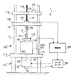
- FIG. 1 is a front view of a vibration test apparatus of the present embodiment.
- the vibration test apparatus of the present embodiment is configured to be able to repetitively apply a tension, compression or bending load to a test object (work) or to vibrate the work.
- directions such as “upper”, “lower”, “right”, “left”, “front”, and “back” are based on the front view of FIG. 1 unless otherwise specified. It will be determined.
- the test apparatus 1 includes an apparatus main body 100 that applies a load to a workpiece W or vibrates the workpiece W, and a servo amplifier 200 for driving a servomotor 120 of the apparatus main body 100. , And a control unit 300 that controls the servo amplifier 200.
- the apparatus body 100 includes a frame 110, a servomotor 120, a linear motion converter 400, a load cell 140, a displacement sensor 150, and adapters 181 and 182.
- the linear motion converter 400 is for converting the rotational movement of the rotation shaft of the servomotor 120 into a movement in the linear direction.
- the linear motion converter 400 is fixed to the upper surface of the table portion 111 of the frame 110 and is connected to the rotational shaft of the servomotor 120.
- the movable table 130 provided on the upper portion of the linear motion converter 400 moves up and down with respect to the table portion 111.
- a lower adapter 181 for holding the work W from below is mounted on the movable table 130.
- An upper stage 160 is suspended from the lower surface of the ceiling 112 of the frame 110. Further, on the upper surface of the table portion 111, a pair of guide bars 171 extending upward in the figure is provided.
- the upper stage 160 is bored in the vertical direction at the end in the left-right direction to form a through hole 161, and a guide bar 171 is passed through the through hole 161, respectively. Therefore, the upper stage 160 is vertically movable along the guide bar 171. Further, by tightening a bolt (not shown) provided on the upper stage 160, the inner diameter of the through hole 161 can be narrowed, whereby the upper stage 160 can be fixed to the guide bar 171. It has become.
- An upper adapter 182 for holding the workpiece W from above is attached to the lower surface of the upper stage 160.
- a load can be applied to the work W by moving the movable table 130 up and down while holding the work W between the upper adapter 182 and the lower adapter 181.
- the upper and lower adapters 182 and 181 are configured to be attachable to and detachable from the upper stage 160 and the movable table 130, respectively, so that an appropriate adapter can be selected according to the type of load to be applied to the work W . 1 is configured to apply a tensile load to the workpiece W, the upper adapter 182 and the lower adapter 181 are chucks for gripping the workpiece.
- an adapter When a compressive load is applied to the workpiece W, an adapter is used in which the lower surface of the upper adapter 182 and the upper surface of the lower adapter 181 are flat so that the workpiece W can be pressed from the vertical direction and compressed.
- an adapter for compression testing and a jig for three-point bending are used in combination.
- the lower adapter 181 having a function of fixing the work W on the movable table 130 is used, and the upper adapter 182 is not used.
- the selection of these adapters is an example, and another type of adapter may be used, or another combination may be used.
- the upper stage 160 is suspended from the ceiling 112 of the frame 110 by a feed screw 175.
- the ceiling 112 is embedded with a rotatable nut 173 which engages with the feed screw 175.
- the nut 173 is connected to a motor 172 disposed on the ceiling 112 by an endless belt, and is rotationally driven by the motor 172 about the axis of the feed screw 175.
- the lower end of the feed screw 175 is connected to a link 174 fixed to the upper stage 160, so that the feed screw 175 does not rotate about its axis with respect to the upper stage 160.
- the feed screw 175 and the upper stage 160 connected to the feed screw 175 are rotated by rotating the nut 173 with the motor 172. It can be driven up and down.
- This function is used to adjust the distance between the adapter 181 and the adapter 182 in accordance with the dimensions of the workpiece W. After adjusting the distance between the adapter 181 and the adapter 182, the upper stage 160 is fixed to the guide bar 171 by tightening bolts before conducting a test.
- the displacement sensor 150 is a sensor (for example, a dial gauge incorporating a rotary encoder) that detects the displacement of the lower adapter 181, that is, the deformation amount of the workpiece W.
- the control unit 300 inputs the target angle, the target angular velocity, and the like to the servo amplifier 200 as needed.
- the servo amplifier 200 controls the drive current of the servomotor 120 based on the target angle, the target angular velocity, and the like input from the control unit 300.
- the outputs of the load cell 140 and the displacement sensor 150 are input to the control unit 300.
- the control unit 300 is based on the load measured by the load cell 140 and the displacement of the movable table 130 measured by the displacement sensor 150.
- a target angle, a target angular velocity, and the like to be input to the servo amplifier 200 can be set.
- the target angular velocity to be applied to the servo amplifier 200 is reduced as the detected load of the load cell 140 approaches the maximum load, and the speed of the movable table 132 becomes zero at the maximum load.
- Control that is, the target angular velocity given to the servo amplifier 200 is 0.
- the control unit 300 can give the servo amplifier 200 a target value such that the displacement amplitude, velocity amplitude or acceleration amplitude of the movable table 132 becomes substantially constant.
- the linear motion converter 400 generally includes a casing 410 having a substantially rectangular parallelepiped shape, and a linear connecting rod 461 which protrudes upward through the upper surface of the casing.
- the movable table 130 is fixed to the upper end of the linear connecting rod 410.
- the rotation shaft of the servomotor 120 is coupled to the input shaft 420 of the linear motion converter 400 via the coupler 123.
- Most of the input shaft 420 is housed in the casing 410, and the input shaft 420 is connected to a linear motion mechanism that converts its rotational motion into a vertical linear motion.
- the vertical movement which is the output of this linear movement mechanism, is transmitted to the linear connecting rod 461. Therefore, when the servomotor 120 is driven, the linear connecting rod 461 moves up and down.
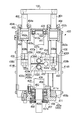
- FIG. 2 is a front view of the linear motion converter 400, in which the front side plate 414F (described later) of the casing 410 is cut to expose the inside of the casing 410.
- FIG. 3 is a side view of the linear motion converter 400 as viewed from the right, in which the right side plate 413R (described later) of the casing 410 is cut to expose the inside of the casing 410.
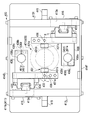
- FIG. 4 is a top view of the linear motion converter 400, in which a top plate 412 (described later) of the casing 410 is cut to expose the inside of the casing 410.
- FIG. 2 the periphery of the upper and lower bearings 451 and 452 that rotatably support the input shaft 420 is shown as a cross-sectional view. Further, in FIG. 3, the peripheries of the upper and lower bearings 451, 452 and the oil seal portion of the linear connecting rod 461 are shown as cross-sectional views. In FIG. 4, the input shaft 420 is indicated by a broken line.
- the casing 410 includes a bottom plate 411, a top plate 412, a left side plate 413L (FIGS. 2 and 4), a right side plate 413R (FIGS. 2 and 4), a near side plate 414F (FIGS. 3 and 4) and a back side plate 414B (FIG. 3). 4) are bolted and connected by welding or the like to form a rectangular solid.
- the bottom plate 411 is fixed to the table portion 111 of the frame 110 with a bolt. Further, the bottom plate 411 is provided with an opening 411 a for passing the input shaft 420. Further, the top plate 412 is provided with an opening 412 a for attaching the upper bearing 451 and an opening 412 b (FIG. 3) for passing the linear connecting rod 461.
- the lateral dimension of the bottom plate 411 is longer than the distance between the right side plate 413R and the left side plate 413L, and both lateral ends of the bottom plate 411 are laterally shaped like flanges from the right side plate 413R and the left side plate 413L. It has become the flange part 411b which overflowed.
- the bottom plate 411 is fixed to the table portion 111 of the frame 110 via a bolt (not shown) at the flange portion 411 b.
- ribs 415 respectively projecting vertically from substantially the center in the depth direction are attached.
- the rib 415 is firmly fixed to the right side plate 413R, the left side plate 413L and the bottom plate 411 by fillet welding.
- Openings 413a are respectively formed at substantially central portions of the right side plate 413R and the left side plate 413L.
- the opening 413 a is used to access the casing 410 when assembling or inspecting the linear motion converter 400.
- the cover 416 is bolted to the right side plate 413R and the left side plate 413 to close the opening 413a.
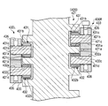
- FIGS. 5 is a cross-sectional view taken along a line II in FIG.
- an external thread portion 421 is formed at a substantially central portion of the input shaft 420.
- a pair of roller units 430L and 430R engaged with the male screw portion 421 is provided on both sides in the left-right direction of the male screw portion 421.
- Each of the roller units 430L and 430R has an upper roller 431, a lower roller 432, a connection plate 433 and a runner block 434.
- the upper roller 431 and the lower roller 432 are fixed to the connection plate 433 by bolts.
- the connection plate 433 is fixed to the runner block 434 by bolts. Accordingly, the runner block 434, the connection plate 433, the upper roller 431 and the lower roller 432 are integrated.
- the pair of runner blocks 434 engage with rails 435 bolted to the inner walls of the right side plate 413R and the left side plate 413L, respectively (FIG. 4).
- the rail 435 extends in the vertical direction (FIGS. 2 and 3), and the moving direction of the roller units 430L and 430R including the runner block 434 is limited to the vertical direction.
- the upper roller 431 and the lower roller 432 respectively have shaft portions 431 a and 432 a and roller portions 431 b and 432 b rotatable around the shaft portions.
- the shaft portions 431a and 432a are fixed to the connection plate 433 by the set screw 436.
- Cylindrical roller bearings 431c, 432c are provided between the roller portions 431b, 432b and the shaft portions 431a, 432a, whereby the roller portions 431b, 432b can rotate around the shaft portions 431a, 432a. ing.
- the male screw portion 421 is a so-called square screw in which the cross-sectional shape of the valley 421 b is substantially rectangular.
- the roller portions 431 b and 432 b have a cylindrical shape, and the roller portion 431 a of the upper roller 431 is a flank 421 c on the upper side of the male screw portion 421 (that is, the upper surface side of the peak 421 a), and the roller portion 432 a of the lower roller 432 is a male screw portion 421.
- the lower side i.e., the lower side of the mountain 421a
- the flanks 421d described later. That is, the roller portions 431 b and 432 b of the roller units 430 L and 430 R are configured to sandwich the ridge 421 a of the male screw portion 421.
- the moving directions of the roller units 430L and 430R are limited only in the vertical direction, and the roller portions 431b and 432b of the upper roller 431 and the lower roller 432 are the flanks 421c of the male screw portion 421 of the input shaft 420, It is in close contact with 421d. Therefore, when the servomotor 120 (FIG. 1) is driven to rotate the input shaft 420, the roller portions 431b and 432b rotate along the flanks 421c and 421d of the male screw portion 421, and the roller units 430L and 430R are input. It is adapted to move up or down depending on the direction of rotation of the shaft 420.
- an opening 433a is formed in substantially the central portion of the connection plate 433 of the roller unit 430R, and from the opening 433a toward the front side of the connection plate 433 (direction toward the front side plate 414F)
- the split groove 433b is formed.
- the shaft portion 431a of the upper roller 431 is fixed to the connection plate 433 on the upper side of the split groove 433b, and the shaft portion 432a of the lower roller 432 is on the lower side of the split groove 433b.
- Through holes 433c and 433d are provided from the upper surface of the connection plate 433 toward the upper surface 433b1 of the slit groove 433b.
- the through holes 433 c and 433 d are both disposed on the near side of the shaft portion 431 a of the upper roller 431, and the through holes 433 c are disposed on the near side of the through hole 433 d.
- a downward hole 433 e is formed at a position opposed to the through hole 433 c on the lower surface 433 b 2 of the split groove 433 b.
- An internal thread is formed in the hole 433e, and a first bolt 437a passes through the through hole 433c and is screwed into the hole 433e. Therefore, when the first bolt 437a is tightened, the connection plate 433 is biased in the direction in which the width of the split groove 433b is narrowed.
- a female screw is also formed in the through hole 433d, and the second bolt 437b is screwed into the through hole 433d. The tip of the second bolt 437b passes through the upper surface 433b1 of the split groove 433b and abuts on the lower surface 433b2. Therefore, when the second bolt 437b is tightened, the connection plate 433 is biased in the direction in which the width of the split groove 433b is expanded.
- the contact between the upper surface of the connection plate 433 and the head of the first bolt 437a restricts the width of the split groove 433b not to widen
- the contact between the lower surface 433b2 of the split groove 433b and the second bolt 437b regulates the width of the split groove 433b not to narrow.
- the flanks 421c and 421d have a large biasing force.
- the roller portions 431 b and 432 b can be in close contact with each other. Since the roller portions 431 b and 432 b are in close contact with the flanks 421 c and 421 d of the male screw portion 421 as described above, the roller portions 431 b and 432 b rotate smoothly without rattling when the input shaft 420 is rotated.
- roller portions 431 b and 432 b of the roller unit 430 L are also urged into close contact with the flanks 421 c and 421 d of the male screw portion 421 of the input shaft 420 by the same configuration as the roller unit 430 R.
- the ridge 421a of the male screw portion 421 is sandwiched between the pair of rollers 431 and 432, the deformation of the ridge 421a of the male screw portion 421 is prevented by the other roller even if a load is applied from one roller. As a result, the mountain 421a is less likely to bend. For this reason, even if the input shaft 420 is rotated at a large angular acceleration, the positional deviation of the roller unit 430R does not occur due to the bending of the mountain 421a.
- roller portions 431 b and 432 b are rotatably supported by the cylindrical roller bearings 431 c and 432 c with respect to the shaft portions 431 a and 432 a.
- the rollers of cylindrical roller bearings are designed to be able to withstand large compressive loads applied in the radial direction, while they are deformed or broken by a relatively small load against shear loads applied in the radial direction. Have. For this reason, in the present embodiment, the load in the shear direction is not applied to the rollers.
- the cylindrical roller bearings 431 c and 432 c are engaged with the peaks 421 a of the male screw portion 421 over substantially the entire axial direction, the cylindrical roller bearings 431 c and 432 c are of the male screw portion 421
- the load received from the mountain 421a is exclusively a compressive load in the radial direction, and almost no load in the shear direction is applied to the rollers. For this reason, even if a large load is acting between the roller portions 431 b and 432 b and the ridge 421 a of the male screw portion 421, the cylindrical roller bearings 431 c and 432 c can sufficiently bear the large load. , 432b can rotate smoothly.
- a rod connecting block 438 (FIGS. 3 and 4) is fixed to the connecting plate 433.
- the lower end 461a of the linear connecting rod 461 is gripped by the rod connecting block 438.
- the gripping structure of the linear connecting rod 461 will be described below.
- the rod connection block 438 is provided with a through hole 438a of circular cross section penetrating in the vertical direction.
- the diameter of the through hole 438 a is slightly larger than the diameter of the lower end 461 a of the linear connecting rod 461.
- a split groove 438b is provided from the inner circumferential surface of the through hole 438a toward the tip of the rod connection block 438 (the right end in the roller unit 430L and the left end in the roller unit 430R).
- through holes 438c and 438d orthogonal to the split grooves 438b are formed.
- the through holes 438 c and 438 d are formed at opposing positions across the split groove 438 b, and an internal thread is formed in the through hole 438 d proximal to the input shaft 420. Therefore, when the linear connecting rod 461 is passed through the through hole 438a and then a bolt is inserted through the through hole 438c and screwed into the through hole 438d, the rod connecting block 438 is deformed so that the diameter of the through hole 438a decreases. The lower end 461 a of the rod 461 is tightened to the rod connection block 438. Thereby, the connecting rod 461 is fixed to the rod connection block 438. Therefore, the connecting rod 461 can be moved up and down by rotating the input shaft 420 by the servomotor 120 (FIG. 1). Further, by controlling the rotational direction of the input shaft 420 to be switched periodically, the connecting rod 461 and the movable table 130 fixed to the upper end of the connecting rod 461 can be vibrated in the vertical direction.
- an upper limit detection sensor 441 is provided on the lower surface of the top plate 412 of the casing 410, and a lower limit detection sensor 442 is provided on the upper surface of the bottom plate 411.
- the upper limit detection sensor 441 and the lower limit detection sensor 442 are both proximity sensors.
- the upper limit detection sensor 441 detects that the upper end of the right roller unit 430R approaches, and the lower limit detection sensor 442 detects that the lower end of the left roller unit 430L approaches.
- the servomotor is urgently stopped.
- the inside of the casing 410 is filled with lubricating oil. For this reason, the friction between the upper and lower rollers 431, 432 and the external thread portion 421 of the input shaft 420 and the friction between the runner block 434 and the rail 435 are reduced.
- the input shaft 420 is rotatably supported at its upper end by the upper bearing 451, which is a ball bearing, and rotated by the lower bearing 452, which is a combined angular ball bearing at the position of the opening 411a of the bottom plate 411. Possible support.
- the upper end of the input shaft 420 is formed with a step portion 422 whose diameter is reduced, and the upper bearing 451 is attached such that the inner ring thereof rides on the step portion 422 .
- a snap ring 423 is fitted to the upper end of the input shaft 420, and the inner ring of the ball bearing 451 is fixed so as not to move in the vertical direction by being pinched by the step portion 422 and the snap ring 423.
- the opening 412 a of the top plate 412 is an interference fit with the outer ring of the upper bearing 451, and the outer ring of the upper bearing 451 is fitted into the opening 412 a of the top plate 412.
- the opening 412 a of the top plate 412 is covered by the cover 453 so that the lubricating oil does not leak.
- the cover 453 is fixed to the top plate 412 by a bolt.
- a circumferential groove 453a is provided on the surface of the cover 453 in contact with the inner circumferential surface of the opening 412a, and the lubricating oil from the gap between the cover 453 and the opening 412a is provided by an O ring not shown attached thereto.
- a stepped portion 424 whose diameter decreases downward is formed in the input shaft 420.
- the upper surface of the inner ring of the lower bearing 452 is disposed to abut on this stepped portion.
- a male screw portion 425 is formed on the outer peripheral surface below the step portion 424 of the input shaft 420.
- the lower bearing 452 is a combined angular bearing and also receives a load in the thrust direction. Therefore, unlike the upper bearing 451, both the inner ring and the outer ring need to be fixed so as not to move vertically.
- a bearing support member 455 for supporting the outer ring of the lower bearing 452 from below is attached to the opening 411 a of the bottom plate 411.
- the bearing support member 455 is a cylindrical member in which a through hole 455c for passing the input shaft 420 is formed at the center, and a flange portion 455a is provided at the lower end thereof.
- the bearing support member 455 is fixed to the bottom plate 411 by fixing the flange portion 455a to the lower surface of the bottom plate 411 with a bolt.
- a circumferential groove 455b is provided at a position facing the inner periphery of the opening 411a on the outer peripheral surface of the bearing support member 455, and the bearing support member 455 and the opening 411a are provided by an O ring (not shown) attached thereto. Prevent the leakage of lubricating oil from the
- a stepped portion 455d is formed such that the inner diameter thereof increases upward.
- a portion of the through hole 455 c above the step portion 455 d is an interference fit with the outer ring of the lower bearing 452, and the outer ring of the lower bearing 452 is fitted here.
- the diameter of the lower part of the through hole 455c from the step portion 455d is substantially equal to the inner diameter of the outer ring of the lower bearing 452, and the outer ring of the lower bearing 452 is supported from below by the step portion 455d.
- a bearing stop 454 is screwed to the upper end of the bearing support member 455.
- the bearing stopper 454 is a holed disk-like member, and the inner diameter of the hole is approximately equal to the inner diameter of the outer ring of the lower bearing 452. Also, the height from the step portion 455 d to the upper end of the bearing support member 455 is equal to or slightly smaller than the height of the lower bearing 452, and the lower bearing can be screwed to the bearing support member 455.
- the outer ring 452 is fixed so as not to move in the vertical direction by being sandwiched between the bearing stopper 454 and the step portion 455 d of the bearing support member 455.
- the oil seal 458 is provided to prevent the lubricating oil from leaking from the gap between the input shaft 420 and the through hole 455c of the bearing support member 455.
- the oil seal 458 is fitted in the hole portion of the oil seal attaching member 457 which is a perforated disk-like member.
- the oil seal attaching member 457 is fixed to the lower surface of the bearing support member 455 by a bolt.
- An annular groove 457a is formed on the upper surface of the oil seal attachment member 457 facing the lower surface of the bearing support member 455, and the lower surface of the bearing support member 455 and the oil are attached by attaching an O-ring not shown here.
- the oil seal 458 is configured such that the inner periphery thereof slides on the outer periphery of the input shaft 420, and rotates the input shaft 420 with low friction, and between the inner periphery of the oil seal 458 and the outer periphery of the input shaft 420 Prevent leakage of lubricating oil from
- the linear connecting rod 461 protrudes upward from the top plate 412 of the casing 410 (FIG. 3). Therefore, in the present embodiment, in order to prevent the leakage of the lubricating oil from the gap between the linear connecting rod 461 and the top plate 412, a cover 464 with an oil seal is provided. The configuration of the cover 464 will be described below.
- the linear connecting rod 461 is supported by a bushing 462 at a position slightly below the top plate 412.
- the inner periphery of the bushing 462 is configured to be slidable with the outer periphery of the linear connecting rod 461.
- the bushing 462 is fixed to the top plate 412 by a bushing attachment member 463 and a cover 464.
- the bush attachment member 463 is fixed to the top plate 412 together with the cover 464 by a bolt (not shown).
- the bushing attachment member 463 is a cylindrical member into which the bushing 462 is fitted, and a lower end portion thereof is provided with a step portion 463a that spreads radially inward.
- the cover 464 is a cylindrically shaped member through which the linear connecting rod 461 passes, the inside diameter of which is smaller than the outer diameter of the bushing 462. Therefore, when the cover 464 and the bushing attachment member 463 are integrated by bolts, the bushing 462 is sandwiched and fixed between the lower surface of the cover 464 and the upper surface of the step portion 463a of the bushing attachment member 463.
- annular groove 462a is provided on the outer periphery of the bushing 462, and by attaching an O-ring not shown here, lubricating oil from the gap between the outer periphery of the bushing 462 and the inner periphery of the bushing attachment member 463 Prevent leaks.
- annular groove 464 b is formed on the outer periphery of the cover 464 facing the inner periphery of the bushing attachment member 463, and the inner periphery of the bushing attachment member 463 and the cover 464 are formed by attaching an O-ring not shown here. Prevent the leakage of lubricating oil from the gap between the
- annular groove 464a is formed on the inner periphery of the cover 464, and an oil seal is attached to the groove 464a.
- the outer periphery of the linear connecting rod 461 moves up and down while sliding with the oil seal, and the oil seal prevents the lubricating oil from leaking from the sliding surface.
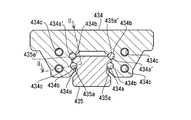
- FIG. 6 is a cross-sectional view of the runner block 434 and the rail 435 cut along a plane perpendicular to the longitudinal direction of the rail 435
- FIG. 7 is a cross-sectional view taken along line II-II of FIG.
- the runner block 434 has a recess formed so as to surround the rail 435, and the recess is formed with four grooves 434a and 434a 'extending in the axial direction of the rail 435. It is done.
- the grooves 434a, 434a ' accommodate a number of stainless steel balls 434b.
- the rail 435 is provided with grooves 435a and 435a 'at positions facing the grooves 434a and 434a' of the runner block 434, and the ball 434b is formed between the groove 434a and the groove 435a or the groove 434a 'and the groove 435a'. It is supposed to be sandwiched between.
- the cross-sectional shape of the grooves 434a, 434a ', 435a, 435a' is a circular arc, and the radius of curvature thereof is approximately equal to the radius of the ball 434b. For this reason, the ball 434b is in close contact with the grooves 434a, 434a ', 435a, 435a' with little play.
- the groove 434a and the withdrawal path 434c are connected at their respective ends via a U-shaped passage 434d, and the groove 434a, the groove 435a, the withdrawal path 434c, and the U-shaped passage 434d are balls.
- the inner diameter of the retraction path 434c and the U-shaped path 434d is slightly larger than the diameter of the ball 434b, and the frictional force generated between the retraction path 434c and the U-shaped path 434d and the ball 434b is very small. This does not disturb the circulation of the balls 434b.
- the two rows of balls 434b sandwiched by the grooves 434a and 435a form a frontal combination angular ball bearing with a contact angle of approximately 45 °.
- the contact angle in this case is an angle formed by the line connecting the contact points where the grooves 434a and 435a contact the balls 434b and the radial direction of the linear guide (the direction from the runner block to the rail).
- the angular ball bearing formed in this manner has loads in the reverse radial direction (direction from the rail to the runner block) and in the lateral direction (direction orthogonal to both the radial direction and the advancing and retracting direction of the runner block; left and right direction in the figure). It can be supported.
- the two rows of balls 434b sandwiched by the grooves 434a 'and 435a' have a contact angle (a line connecting contact points where the grooves 434a 'and 435a' make contact with the balls 434b and the reverse of the linear guide
- a frontal combination type angular contact ball bearing is formed in which the angle with the radial direction is 45 °.
- the angular ball bearing can support radial and lateral loads.
- the two rows of balls 434b respectively sandwiched by one of the grooves 434a and 435a (left side in the drawing) and one of the grooves 434a 'and 435a' (left side in the drawing) are also frontal combination type angular contact ball bearings
- two rows of balls 434b respectively sandwiched by the other of grooves 434a and 435a (left side in the figure) and the other of grooves 434a 'and 435a' (left side in figure) are also frontal combination type angular ball bearings
- the front combination type angular contact ball bearings support the loads acting in the radial direction, the reverse radial direction, and the lateral direction, respectively, and are applied in directions other than the rail axial direction. It can support a large load well.
- FIG. 8 shows a vibration waveform measured by the vibration pickup attached on the movable table 130 when the vibration test apparatus 1 of the present embodiment is driven at an acceleration amplitude of 0.7 G and a frequency of 5 Hz.
- the movable table 130 can be oscillated with an acceleration waveform with less noise (close to a sine wave).
- FIG. 9 shows a vibration waveform measured by a vibration pickup mounted on a movable table when the vibration test apparatus of the comparative example is driven at an acceleration amplitude of 0.7 G and a frequency of 5 Hz.
- spike noise generated due to a collision between balls of a ball screw mechanism or the like is generated, and the movable table can not be oscillated with an acceleration waveform close to a sine wave. I understand.
Landscapes
- Physics & Mathematics (AREA)
- General Physics & Mathematics (AREA)
- Health & Medical Sciences (AREA)
- Life Sciences & Earth Sciences (AREA)
- Chemical & Material Sciences (AREA)
- Analytical Chemistry (AREA)
- Biochemistry (AREA)
- General Health & Medical Sciences (AREA)
- Immunology (AREA)
- Pathology (AREA)
- Transmission Devices (AREA)
- Investigating Strength Of Materials By Application Of Mechanical Stress (AREA)
Priority Applications (1)
| Application Number | Priority Date | Filing Date | Title |
|---|---|---|---|
| CN2008801061109A CN101796383B (zh) | 2008-05-14 | 2008-11-28 | 振动试验装置 |
Applications Claiming Priority (2)
| Application Number | Priority Date | Filing Date | Title |
|---|---|---|---|
| JP2008-127261 | 2008-05-14 | ||
| JP2008127261A JP4812802B2 (ja) | 2008-05-14 | 2008-05-14 | 振動試験装置、直動アクチュエータ及び直動変換器 |
Publications (1)
| Publication Number | Publication Date |
|---|---|
| WO2009139089A1 true WO2009139089A1 (ja) | 2009-11-19 |
Family
ID=41318469
Family Applications (1)
| Application Number | Title | Priority Date | Filing Date |
|---|---|---|---|
| PCT/JP2008/071735 Ceased WO2009139089A1 (ja) | 2008-05-14 | 2008-11-28 | 振動試験装置 |
Country Status (5)
| Country | Link |
|---|---|
| JP (1) | JP4812802B2 (enExample) |
| KR (1) | KR101262804B1 (enExample) |
| CN (1) | CN101796383B (enExample) |
| TW (1) | TWI454681B (enExample) |
| WO (1) | WO2009139089A1 (enExample) |
Cited By (7)
| Publication number | Priority date | Publication date | Assignee | Title |
|---|---|---|---|---|
| CN104614237A (zh) * | 2015-03-04 | 2015-05-13 | 中铁第五勘察设计院集团有限公司 | 表面振动压实试验仪参数检测装置 |
| CN107389481A (zh) * | 2017-08-02 | 2017-11-24 | 中国地震局工程力学研究所 | 疲劳试验机 |
| EP3255403A1 (de) * | 2016-06-07 | 2017-12-13 | Prisma Engineering Maschinen- und Motorentechnik GmbH | Schwinglast, prüfstand zum schwingungsprüfen und verfahren hiefür |
| CN111272572A (zh) * | 2019-11-04 | 2020-06-12 | 于重久 | 多头拉伸试验机 |
| CN111272573A (zh) * | 2019-11-04 | 2020-06-12 | 于重久 | 多头持久蠕变试验机 |
| US11656148B2 (en) * | 2020-05-18 | 2023-05-23 | Hyundai Motor Company | Elastic material vibration test apparatus |
| CN120521707A (zh) * | 2025-07-24 | 2025-08-22 | 宁波银球科技股份有限公司 | 轴承测振机及轴承装配装置 |
Families Citing this family (9)
| Publication number | Priority date | Publication date | Assignee | Title |
|---|---|---|---|---|
| CN102853981B (zh) * | 2012-09-28 | 2015-04-29 | 中国科学院力学研究所 | 一种可模拟大幅值振动系统的实验装置 |
| CN103575491B (zh) * | 2013-11-12 | 2016-04-20 | 中国航空工业集团公司北京航空制造工程研究所 | 空心结构高周疲劳振动测试装置及方法 |
| CN104020038B (zh) * | 2014-06-17 | 2016-05-25 | 山东大学 | 一种振动试验台用组合测试附件及静态疲劳试验方法 |
| CN105841905B (zh) * | 2016-05-23 | 2018-07-06 | 中国工程物理研究院总体工程研究所 | 一种可自动调心的直线运动补偿装置 |
| KR101866134B1 (ko) * | 2017-04-28 | 2018-06-08 | 한국항공우주연구원 | 음향센서 배열 조정장치 |
| CN111721396A (zh) * | 2020-06-30 | 2020-09-29 | 广州百畅信息科技有限公司 | 一种基于传感技术的检测振动装置 |
| CN114199601B (zh) * | 2021-12-08 | 2023-09-01 | 西安苏试广博环境可靠性实验室有限公司 | 一种新型的滚筒式元器件加速度试验设备 |
| KR102545912B1 (ko) * | 2023-02-23 | 2023-06-21 | 한국원자력로봇 유한책임회사 | 햅틱 하중 피드백 인가장치 |
| CN119321959B (zh) * | 2024-11-25 | 2025-10-17 | 北京靖宏云泰科技有限公司 | 基于建筑钢混结构的实体抗压强度的测试方法 |
Citations (3)
| Publication number | Priority date | Publication date | Assignee | Title |
|---|---|---|---|---|
| JPH03277810A (ja) * | 1990-03-23 | 1991-12-09 | Nippon Seiko Kk | 耐衝撃性リニアガイド装置 |
| JPH11153205A (ja) * | 1997-11-19 | 1999-06-08 | Nippon Seiko Kk | 直進運動装置 |
| JP2001141599A (ja) * | 1999-11-11 | 2001-05-25 | Kayaba Ind Co Ltd | 振動/加振試験機 |
Family Cites Families (4)
| Publication number | Priority date | Publication date | Assignee | Title |
|---|---|---|---|---|
| TW463019B (en) * | 1999-07-08 | 2001-11-11 | Isel Co Ltd | Ball screw and linearly movable apparatus using the ball screw |
| JP4814438B2 (ja) | 2001-05-02 | 2011-11-16 | 日本トムソン株式会社 | リニアモータを内蔵したステージ装置 |
| KR200335646Y1 (ko) | 2003-09-01 | 2003-12-11 | 주식회사 네스지오 | 진동방향 전환 장치 및 이를 구비한 진동 시험 장치 |
| JP4575674B2 (ja) * | 2004-01-23 | 2010-11-04 | Thk株式会社 | 回転テーブル装置 |
-
2008
- 2008-05-14 JP JP2008127261A patent/JP4812802B2/ja active Active
- 2008-11-28 KR KR1020097027273A patent/KR101262804B1/ko active Active
- 2008-11-28 WO PCT/JP2008/071735 patent/WO2009139089A1/ja not_active Ceased
- 2008-11-28 CN CN2008801061109A patent/CN101796383B/zh active Active
-
2009
- 2009-05-07 TW TW098115077A patent/TWI454681B/zh active
Patent Citations (3)
| Publication number | Priority date | Publication date | Assignee | Title |
|---|---|---|---|---|
| JPH03277810A (ja) * | 1990-03-23 | 1991-12-09 | Nippon Seiko Kk | 耐衝撃性リニアガイド装置 |
| JPH11153205A (ja) * | 1997-11-19 | 1999-06-08 | Nippon Seiko Kk | 直進運動装置 |
| JP2001141599A (ja) * | 1999-11-11 | 2001-05-25 | Kayaba Ind Co Ltd | 振動/加振試験機 |
Cited By (8)
| Publication number | Priority date | Publication date | Assignee | Title |
|---|---|---|---|---|
| CN104614237A (zh) * | 2015-03-04 | 2015-05-13 | 中铁第五勘察设计院集团有限公司 | 表面振动压实试验仪参数检测装置 |
| EP3255403A1 (de) * | 2016-06-07 | 2017-12-13 | Prisma Engineering Maschinen- und Motorentechnik GmbH | Schwinglast, prüfstand zum schwingungsprüfen und verfahren hiefür |
| CN107389481A (zh) * | 2017-08-02 | 2017-11-24 | 中国地震局工程力学研究所 | 疲劳试验机 |
| CN107389481B (zh) * | 2017-08-02 | 2023-05-26 | 中国地震局工程力学研究所 | 疲劳试验机 |
| CN111272572A (zh) * | 2019-11-04 | 2020-06-12 | 于重久 | 多头拉伸试验机 |
| CN111272573A (zh) * | 2019-11-04 | 2020-06-12 | 于重久 | 多头持久蠕变试验机 |
| US11656148B2 (en) * | 2020-05-18 | 2023-05-23 | Hyundai Motor Company | Elastic material vibration test apparatus |
| CN120521707A (zh) * | 2025-07-24 | 2025-08-22 | 宁波银球科技股份有限公司 | 轴承测振机及轴承装配装置 |
Also Published As
| Publication number | Publication date |
|---|---|
| JP4812802B2 (ja) | 2011-11-09 |
| TW200946891A (en) | 2009-11-16 |
| JP2009276190A (ja) | 2009-11-26 |
| KR20110008139A (ko) | 2011-01-26 |
| KR101262804B1 (ko) | 2013-05-09 |
| CN101796383A (zh) | 2010-08-04 |
| CN101796383B (zh) | 2013-03-20 |
| TWI454681B (zh) | 2014-10-01 |
Similar Documents
| Publication | Publication Date | Title |
|---|---|---|
| WO2009139089A1 (ja) | 振動試験装置 | |
| JP7240021B2 (ja) | タイヤ試験装置 | |
| KR101223548B1 (ko) | 만능 시험 장치, 직동 액추에이터, 및 비틀림 시험 장치 | |
| JP5220899B2 (ja) | セミリジッドカップリング、連結機構、駆動機構及び加振装置 | |
| JP5351939B2 (ja) | 加振装置 | |
| KR102781431B1 (ko) | 하모닉 감속기용 소음 측정장치 | |
| JP2009075064A (ja) | 万能試験装置及び直動アクチュエータ | |
| JP2008267939A (ja) | ねじり試験装置 | |
| JP2016194365A (ja) | 一軸アクチュエータおよびこれを備える一軸アクチュエータ装置 | |
| JP2014527386A (ja) | 電動シリンダ及び電動シリンダシステム | |
| CN206399365U (zh) | 用于监测轴承轴向游隙的监测装置以及风力发电机组 | |
| JP2020501495A (ja) | 電動アクチュエータ | |
| CN112577842A (zh) | 一种微动磨损实验装置 | |
| JP5388185B2 (ja) | 防振器用試験装置 | |
| CN104596750A (zh) | 波形膨胀节性能检测装置 | |
| CN120488908A (zh) | 输入轴与连接轴组装后轴承档跳动检测设备及方法 | |
| JPH08178904A (ja) | 超音波探傷装置 | |
| CN107607337A (zh) | 动车组液压作动器激振双短轴摆动接地装置试验台 | |
| JP2013032803A (ja) | シリンダ装置 |
Legal Events
| Date | Code | Title | Description |
|---|---|---|---|
| WWE | Wipo information: entry into national phase |
Ref document number: 200880106110.9 Country of ref document: CN |
|
| ENP | Entry into the national phase |
Ref document number: 20097027273 Country of ref document: KR Kind code of ref document: A |
|
| 121 | Ep: the epo has been informed by wipo that ep was designated in this application |
Ref document number: 08874280 Country of ref document: EP Kind code of ref document: A1 |
|
| NENP | Non-entry into the national phase |
Ref country code: DE |
|
| 122 | Ep: pct application non-entry in european phase |
Ref document number: 08874280 Country of ref document: EP Kind code of ref document: A1 |