WO2009133601A1 - Joining tool and frame structure - Google Patents
Joining tool and frame structure Download PDFInfo
- Publication number
- WO2009133601A1 WO2009133601A1 PCT/JP2008/058207 JP2008058207W WO2009133601A1 WO 2009133601 A1 WO2009133601 A1 WO 2009133601A1 JP 2008058207 W JP2008058207 W JP 2008058207W WO 2009133601 A1 WO2009133601 A1 WO 2009133601A1
- Authority
- WO
- WIPO (PCT)
- Prior art keywords
- frame
- fixing member
- joint
- engaging body
- pipe
- Prior art date
Links
- 238000000034 method Methods 0.000 description 18
- 238000003780 insertion Methods 0.000 description 13
- 230000037431 insertion Effects 0.000 description 13
- XEEYBQQBJWHFJM-UHFFFAOYSA-N Iron Chemical compound [Fe] XEEYBQQBJWHFJM-UHFFFAOYSA-N 0.000 description 6
- 239000000463 material Substances 0.000 description 4
- 229910000831 Steel Inorganic materials 0.000 description 3
- 229910052742 iron Inorganic materials 0.000 description 3
- JEIPFZHSYJVQDO-UHFFFAOYSA-N iron(III) oxide Inorganic materials O=[Fe]O[Fe]=O JEIPFZHSYJVQDO-UHFFFAOYSA-N 0.000 description 3
- 230000000149 penetrating effect Effects 0.000 description 3
- 239000010959 steel Substances 0.000 description 3
- 230000002265 prevention Effects 0.000 description 2
- 238000003466 welding Methods 0.000 description 2
- 229910000838 Al alloy Inorganic materials 0.000 description 1
- 210000000078 claw Anatomy 0.000 description 1
- 238000010586 diagram Methods 0.000 description 1
- 229910052751 metal Inorganic materials 0.000 description 1
- 239000002184 metal Substances 0.000 description 1
- 238000003825 pressing Methods 0.000 description 1
- 239000011347 resin Substances 0.000 description 1
- 229920005989 resin Polymers 0.000 description 1
- 238000000926 separation method Methods 0.000 description 1
Images


Classifications
-
- F—MECHANICAL ENGINEERING; LIGHTING; HEATING; WEAPONS; BLASTING
- F16—ENGINEERING ELEMENTS AND UNITS; GENERAL MEASURES FOR PRODUCING AND MAINTAINING EFFECTIVE FUNCTIONING OF MACHINES OR INSTALLATIONS; THERMAL INSULATION IN GENERAL
- F16B—DEVICES FOR FASTENING OR SECURING CONSTRUCTIONAL ELEMENTS OR MACHINE PARTS TOGETHER, e.g. NAILS, BOLTS, CIRCLIPS, CLAMPS, CLIPS OR WEDGES; JOINTS OR JOINTING
- F16B7/00—Connections of rods or tubes, e.g. of non-circular section, mutually, including resilient connections
- F16B7/02—Connections of rods or tubes, e.g. of non-circular section, mutually, including resilient connections with conical parts
- F16B7/025—Connections of rods or tubes, e.g. of non-circular section, mutually, including resilient connections with conical parts with the expansion of an element inside the tubes due to axial movement towards a wedge or conical element
Definitions
- This case relates to a joint for joining a plurality of frames, a frame structure including two frames and a joint for joining the two frames.
- a frame structure constructed by joining strong frames such as metal pipes is known, and such a frame structure is a load such as a skeleton part of a shelf or a handrail. It is often used for structures requiring great durability against the above.
- a method of joining the frames by welding and a method of driving rivets to join the frames are known.
- the method of joining by welding has the advantage that the joining state is strong, rust (rust) is likely to occur at the joint part, so post-treatment is necessary to prevent rust, and it takes time and labor to join There are drawbacks.
- the method of driving the rivets to join the frames to each other is easy to join, but has a drawback that the joining portion becomes large due to the necessity of driving a plurality of rivets to strengthen the joining state.
- a pipe fixing device for fixing a pipe constituting a handrail to a fixing target has been proposed (see, for example, Patent Document 1).
- an object of the present invention is to provide a connector and a frame structure in which joining work is simple and the enlargement of the joining portion is suppressed when joining a plurality of frames.
- the basic form of the connector that achieves the above object is as follows: A joint for joining a plurality of frames, An engagement body comprising a plurality of engagement members inserted into the first frame of the plurality of frames and engaged with the plurality of engagement portions of the first frame; And a fixing member having a tapered shape that is inserted into a space formed by the engagement body and pushes the engagement body.
- engagement means a state of being caught by some physical structure
- engagement portion means a portion having such a physical structure of being caught.
- the “engagement body” has a physical structure that is caught by the “engagement portion” and also has a structure that can be expanded by the “fixing member”.
- the physical structure on which the “engagement part” and the “engagement body” are caught may be a structure in which one is convex and the other is concave, or a structure in which both are convex.
- the “engagement part” preferably has a hole, and the “engagement body” has a protrusion that fits into the hole.
- the engaging member that engages with the first frame inside the first frame pushes the fixing member toward the first frame inside the first frame.
- this fixing member is joined to another frame among a plurality of frames by, for example, bolts or the like, thereby realizing the joining of the frames.
- the joining work is simple as described above, and since the joining tool is inserted into the frame, enlargement of the joining portion can be suppressed.
- the basic form of the frame structure that achieves the above object is as follows: A first frame; A second frame connected to the first frame; A frame structure including the first frame and a joint for connecting the second frame,
- the connector is An engaging body inserted into the first frame and engaged with a plurality of engaging portions of the first frame; and a plurality of the first frame inserted into a space formed by the engaging body.
- An engaging body comprising a plurality of engaging members respectively engaged with the engaging portion, and a fixing member having a tapered shape that is inserted into a space formed by the engaging body and pushes the engaging body. Is.
- the joining operation is simplified and the enlargement of the joining portion is suppressed when joining a plurality of frames.
- FIG. 4 is an exploded view of the joint shown in FIG. 3.
- FIG. 4 is a bottom view of the joint when the joint shown in FIG. 3 is viewed from below in FIG. 3.
- It is sectional drawing in the plane along the vertical direction of FIG. 3 of the joint shown in FIG. It is sectional drawing showing a mode when the joint of FIG. 2 is inserted in the pipe extended in the vertical direction of FIG.
- FIG. 1 is a diagram showing a rack 1 which is a specific embodiment of a frame structure.
- Part (a) of FIG. 1 shows a state when the rack 1 is viewed obliquely from above, and part (b) of FIG. 1 shows the rack 1 of part (a) of FIG. The state when it sees from the back side of the part (a) of FIG. 1 shown by A is shown.
- the rack 1 is a rack for housing the server 1a, and a skeleton of the rack 1 is formed by joining a plurality of pipes 10.
- FIG. 2 is a view showing a joining mechanism for joining the two pipes 10 of FIG.
- one of the two pipes 10 is a pipe 10 and the other is a pipe 10 ′. I do.
- the two pipes 10 and 10 ' are square pipes having a hollow inside and a square cross section.
- the pipe 10 extending in the longitudinal direction in the figure and a right angle to the pipe 10 are shown.
- a state is shown in which another pipe 10 ′ extending in a direction (hereinafter referred to as a lateral direction) is joined.
- the pipe 10 extending in the vertical direction in the figure moves in the direction indicated by the downward arrow in the figure, so that the joint 100 is inserted into the pipe 10 and is fixed inside the pipe 10 by the method described later. Is done.
- a first bolt insertion port 10a and a second bolt insertion port 10a ′ are provided on the side surface of the pipe 10 ′ extending in the lateral direction, and when the two pipes 10, 10 ′ are joined, the bolt 20 is It is inserted in the direction of the upward arrow in the figure, and is fastened to the joint 100 via the second bolt insertion port 10a ′ and the first bolt insertion port 10a.
- the fastening of the bolt main body 20a and the joint 100 will be described in detail in the description of the joining between the two pipes 10 and 10 'shown in FIG.
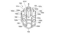
- FIG. 3 is a view showing the joint 100
- FIG. 4 is an exploded view of the joint 100 shown in FIG.
- the joint 100 includes a block 101, four plates 102 surrounding the block 101, and an O-ring 103 that presses the four plates 102 against the block 101.
- the block 101 and the plate 102 are members made of a steel material mainly composed of iron
- the O-ring 103 is a rubber member.
- the plate 102 will be described as a member made of a steel material mainly composed of iron.
- an aluminum alloy or a resin is used in addition to the steel material mainly composed of iron. It may be adopted.
- the “engagement body” in the basic form of the connector and the frame structure described above may be an assembly of a plurality of members or a single member, but “the engagement body is composed of a plurality of plates.
- the application form “is” is suitable. According to this preferred application mode, since the “fixing member” is inserted between the plurality of plates, the plates spread smoothly and engage with the “engagement portion”, so that the joining is realized smoothly.
- the block 101 corresponds to an example of the fixing member in the basic form of the joint and the basic form of the frame structure
- the combination of the four plates 102 is the basic form and the frame of the joint.
- the four plates 102 correspond to an example of “a plurality of plates” in the application mode described above.
- the direction in which the joint 100 is relatively inserted with respect to the pipe 10 extending in the vertical direction in FIG. 2 is represented by an upward arrow B in FIG. 4.
- the four block side surfaces 101c that contact the four plates 102 are inclined obliquely with respect to the insertion direction indicated by the arrow B.
- the block 101 as a whole has a quadrangular truncated pyramid shape that tapers in a direction opposite to the insertion direction (downward direction in the figure).
- the tapered shape is said to be a tapered shape
- the shape of the truncated pyramid that is tapered in the downward direction as described above is the tapered shape in the basic form of the joint and the basic form of the frame structure described above. It corresponds to an example.
- the shape of the truncated pyramid other than the square truncated pyramid is not limited to that of the block 101 having the truncated pyramid shape as described above.
- the block 101 may be the same, or the truncated cone-shaped block 101 may be used.
- Each of the four block side surfaces 101c of the block 101 is provided with a groove portion 101a extending in parallel with the insertion direction.
- the four plates 102 are provided with convex portions 102a that fit into the groove portions 101a. When the block 101 comes into contact with the four plates 102, the convex portions 102a of the plates 102 are It fits in each groove 101a of the block 101.
- the engaging body is provided with a convex portion on a surface that contacts the fixing member, and the fixing member includes the convex portion and
- the application mode that “a concave portion to be fitted” is provided is preferable.
- the “concave portion” is formed in, for example, a groove shape so as not to prevent insertion of the “fixing member” for expanding the “engaging body”.
- the movement direction of the “engagement body” is restricted by the fitting of the “convex portion” and the “concave portion”, and the “engaging portion” is surely Will be engaged.
- Each groove 101a of the block 101 corresponds to an example of a recess in this application mode
- the projection 102a of the plate 102 corresponds to an example of a projection in this application mode.
- the block 101 is formed with a through hole 1010 penetrating the inside of the block 101 in the vertical direction of FIG.
- a spiral thread groove is formed on the wall surface of the through hole 1010.
- the spiral screw portion formed on the side surface of the bolt main body 20a in FIG. 2 rotates the bolt 20 with the insertion direction of the bolt 20 as the rotation axis. Fit into the above thread groove.
- the screw portion on the side surface of the bolt main body portion 20a is fitted in the screw groove on the wall surface of the through hole 1010 of the block 101 as the bolt 20 rotates, so that the block 101 and the bolt 20 described above in FIG. A strong bond between is realized.
- the fixing member is fastened at one end to a fastening member inserted into an opening provided in the second frame among the plurality of frames.
- fastening means tightening by being moved by a hand or a tool (that is, “fastening operation”), and thus “fastening member” is connected to “fastening portion” by some physical structure, This means that the “fastening portion” and the “fixing member” can be pulled to the “second frame” by the “fastening operation”.
- the “fastening member” is inserted into the “opening portion” and one end is fastened to the “fastening portion”, and the other end with respect to the one end is caught in the “second frame” side in some form.
- the bolt 20 is an example of a fastening member in the above-described application mode, and a portion provided with the through hole 1010 of the block 101 functions as an example of a fastening portion for the fastening member.
- a bolt-nut mechanism that is fastened by screw engagement can be applied to the “fastening member” and the “fastening portion”.
- a mechanism or a mechanism that is fastened by catching between a gear and a claw can be applied. According to such a preferred application mode, the frames can be easily and reliably joined by the fastening operation.
- FIG. 5 is a bottom view of the joint 100 when the joint 100 shown in FIG. 3 is viewed from below in FIG. 3, and
- FIG. 6 is a cross-sectional view of the joint 100 shown in FIG. 3 in a plane along the vertical direction of FIG. FIG.
- the four plates 102 are arranged so as to surround the center O with the adjacent plates 102 in contact with the adjacent plate contact surfaces 102 c.
- a substantially circular opening centered on the center O is formed on the bottom surface of the joint 100.
- this opening is an opening into which the bolt 20 is inserted so that the joint 100 is fastened to the bolt 20 of FIG.
- the four plates 102 form a quadrangular frustum-shaped space into which the block 101 is inserted, and have a substantially quadrangular frustum-shaped cylinder shape surrounding the space.
- the four plates 102 arranged as described above are tightened from the outside by O-rings 103 surrounding the four plates 102 as shown in FIG.
- O-rings 103 surrounding the four plates 102 as shown in FIG.
- the shape of FIG. 5 in which the four plates 102 surround the center O with the adjacent plate contact surfaces 102c in contact with each other is firmly held.
- an O-ring fixing groove 102d shown in FIG. 4 is provided in a portion of the four plates 102 in contact with the O-ring 103.
- the O-ring 103 By fitting the O-ring 103 into the O-ring fixing groove 102d, The O-ring 103 is prevented from shifting in the vertical direction in the figure, and the state where the four plates 102 are in contact with each other at the adjacent plate contact surface 102c as shown in FIG. 5 is maintained.
- the “engagement body” is an aggregate of a plurality of plates
- the “predetermined shape” is a shape that forms a space in which the “fixing member” is inserted, and is a shape that surrounds the space with a plurality of plates.
- the O-ring 103 described above corresponds to an example of the holding member.
- FIG. 6 shows a cross section of the joint 100 in a plane extending in the lateral direction of FIG. 5 passing through the center O of FIG.
- FIG. 6 shows a state in which the convex portion 102a of the plate 102 is fitted into the groove portion 101a of the block 101 within the dotted circle in this figure.
- the convex part 102a is caught by the terminal part 1010a of the groove part 101a of the block 101, and therefore, the block 101 is prevented from shifting upward from the state shown in FIG. .
- This terminal portion 1010a corresponds to an example of the “drop-off prevention portion”.
- the block 101 cannot move upward as compared with the state shown in FIG. 6, but can move downward, and the convex portion 102 a of the plate 102 remains along the groove portion 101 a of the block 101.
- the right plate 102 of FIG. receives a force pushed away from the block 101 in the left direction.
- FIG. 6 In the above description of FIG. 6, the left and right two plates 102 in FIG. 6 among the four plates 102 in FIG. 4 have been described, but the front side and the back side of the block 101 in FIG. In FIG. 6, there is a plate 102 (not shown), and when the block 101 moves downward from the state shown in FIG. 6, these plates 102 also receive a force pushed away from the block 101.
- the engaging body has a tapered shape corresponding to the tapered shape of the fixing member formed on the contact surface with the fixing member”.
- the application form is suitable.
- “the taper shape is formed” means that the “contact surfaces” form a taper shape
- “the taper shape corresponding to the taper shape of the fixing member” means “ It means that the angle between the “contact surfaces” is the same as the taper angle in the taper shape of the “fixing member”. According to such an application mode, the “fixing member” is brought into contact with the entire “abutting surface” to realize strong bonding.
- the left and right plates 102 in FIG. 6 each have a block abutting surface 102 e that abuts the block 101, which is inclined with respect to the vertical direction in FIG. 6 in accordance with the taper shape of the block 101. The situation is shown.
- FIG. 7 is a cross-sectional view showing a state when the joint 100 of FIG. 2 is inserted into the pipe 10 extending in the vertical direction of FIG.
- FIG. 7 shows the same cross section as that of FIG. 6 with respect to the cross section of the joint 100, and FIG. 7 also shows the cross section of the pipe 10 extending in the longitudinal direction of FIG. 2 into which the joint 100 is inserted. Yes.
- the plate 102 is provided with a protruding portion 102b protruding toward the pipe 10 in FIG. 7 on the surface (front surface) opposite to the surface in contact with the block 101.
- the protruding portion 102b When viewed from the front surface of 102, it has a disk-like shape as shown in the protrusion 102b of FIG.
- a joint fixing opening 10b is provided on the side surface of the pipe 10, and the joint fixing opening 10b has the same size as the protrusion 102b. It is a disk-shaped opening. Further, the positions (heights) of the protrusions 102b and the joint fixing opening 10b are aligned at the lower end of the joint 100 and the lower end of the pipe 10 as shown in FIG.
- FIG. 8 is a view showing a state in which the two pipes 10 and 10 ′ of FIG. 2 are joined by the joint 100 and the bolt 20.
- the bolt 20 passes through the second insertion port 10 a ′.
- the bolt body 20 of the bolt 20 is inserted into the circular opening shown in FIG. 5 formed by the four plates 102 of the joint 100.
- the bolt 20 is tightened (the bolt 20 rotates with the insertion direction of the bolt 20 as a rotation axis), so that the screw portion on the side surface of the front end portion (upper end portion in this figure) of the bolt main body portion 20a is blocked.
- 101 begins to fit into the thread groove on the wall surface of the through-hole 1010, whereby the entire bolt 20 moves upward in the figure.
- the movement of the bolt 20 continues until the bolt head portion 20a 'reaches the first insertion port 10a.
- the bolt 20 can no longer move upward in the figure.
- the block 101 is now moved to the bolt 20 side. The downward movement is started so as to be attracted.
- Part (b) of FIG. 8 shows a state when the block 101 starts to move downward by the rotation of the bolt 20.
- the four plates 102 are pressed toward the wall surface of the upper pipe 10 in the figure by the taper shape of the block 101 and the plate 102 described above in FIG. Go. Due to this pressing force, the protruding portion 102b of each plate 102 is pushed into the joint fixing opening 10b of the upper pipe 10. Further, when the four plates 102 are pressed toward the wall surface of the upper pipe 10 in the figure, the O-ring 103 is crushed between the four plates 102 and the wall surface of the upper pipe 10. And pushed into the O-ring fixing groove 102d.
- Part (c) of Fig. 8 shows a state in which the protruding portion 102b of each plate 102 is completely fitted into the joint fixing opening 10b of the upper pipe 10.
- the protrusions 102 b of the plates 102 are fitted into the joint fixing openings 10 b of the upper pipe 10, so that the joint 100 is made of the part (c) of FIG. 8.
- the joint 100 cannot be moved in the vertical direction, and the joint 100 is firmly fixed to the upper pipe 10.
- the O-ring 103 is completely pushed into the O-ring fixing groove 102d.
- the block 101 corresponds to an example of a fixing member in the basic form of the connector and the basic form of the frame structure
- the combination of the four plates 102 is the above-described connector.
- This corresponds to an example of the engaging body in the basic form and the basic form of the frame structure.
- the joint fixing opening 10b corresponds to an example of the engaging portion in the basic form of the connector and the basic form of the frame structure. That is, in the present embodiment, as an engagement method between the “engagement body” and the “engagement portion”, a method is employed in which the “engagement body” having the protrusion is fitted into the “engagement portion” having the opening.
- the joint 100 is inserted into the upper pipe 10 in FIG. 8, and the bolt 20 is inserted into the lower pipe 10 ′.
- the two pipes 10 and 10 ' can be easily joined.
- the joint 100 and the bolt 20 are accommodated in the pipes 10 and 10 ', enlargement of the joint portion is suppressed.
- the joints 100 are firmly fixed to the upper pipe 10 by fitting the protrusions 102b of the respective plates 102 into the joint fixing openings 10b of the upper pipe 10 in FIG.
- the joint can be fixed to the pipe.
- each plate 102 is pressed against the wall surface of the pipe, whereby the frictional force between each plate 102 and the wall surface of the pipe increases, and this joint is fixed to the upper pipe by this frictional force. Is done.
- each plate 102 to be pressed against the wall surface of the upper pipe 10
- the block 101 rotates around the bolt 20. May move downward.
- the pipes 10 and 10 ′ to be joined are square pipes having a hollow inside and a square cross section.
- a frame is used in each of the basic forms of the joining tool and the frame structure described above.
- a square pipe having a cross section other than a square or a cylindrical pipe may be employed in each of the basic forms of the joining tool and the frame structure described above.
- the inner wall of the upper pipe 10 in FIG. 8 that contacts the joint 100 is also tapered to increase the frictional force between the joint 100 and the upper pipe 10 in FIG. 8 may be devised so as to be easily fixed to the upper pipe 10.
- the block 101 is provided with the through hole 1010 penetrating the block 101 in order to fasten the bolt main body portion 20a.
- the hole for fastening the bolt body 20a Any hole having an opening on the side into which the portion 20 a is inserted may be used, and the hole is not necessarily a through hole penetrating the block 101.
Abstract
A joining tool for joining frames to each other includes an engagement body comprising engagement members inserted into the first frame among a plurality of frames and with the engagement parts of the first frame, and a fixing member inserted into the space formed by the engagement body and tapered so as to push and expand the engagement body. Furthermore, a frame structure comprising a first frame, a second frame connected to the first frame and the joining device for connecting the first frame to the second frame is provided.
Description
本件は、複数のフレームを接合する接合具と、2つのフレームおよびこれら2つのフレームを接合する接合具を備えたフレーム構造体とに関する。
This case relates to a joint for joining a plurality of frames, a frame structure including two frames and a joint for joining the two frames.
従来から、金属パイプのように丈夫なフレーム同士を接合することで構成されたフレーム構造体が知られており、こうしたフレーム構造体は、棚(ラック)の骨格部分や手すりなどのような、負荷に対する大きな耐久性が要求される構造物に用いられることが多い。
Conventionally, a frame structure constructed by joining strong frames such as metal pipes is known, and such a frame structure is a load such as a skeleton part of a shelf or a handrail. It is often used for structures requiring great durability against the above.
フレームを複数組み合わせる方式としては、フレーム同士を溶接によって接合する方式や、リベットを打ち込んでフレーム同士を接合する方式が知られている。溶接によって接合する方式には、接合状態が強固であるという利点があるものの、接合部分に錆(さび)が発生しやすいので錆防止のための後処理が必要となり、接合作業に手間がかかるという欠点がある。一方、リベットを打ち込んでフレーム同士を接合する方式には、接合作業は簡単であるが、接合状態を強固にするため複数のリベットを打ち込む必要性から接合部分が大きくなってしまうという欠点がある。最近では、手すりを構成するパイプを固着目標に固着させるためのパイプ固着装置が提案されており(例えば、特許文献1参照)、このパイプ固着装置では、固着目標となる部材上に設けられたパイプ固着装置の嵌合部を、パイプ内部に嵌りこませることでパイプが固着される。このパイプの固着方式では、パイプの固着処理が簡単で接合部分も小さくてすむという利点がある。
特開平11-311006号公報
As a method of combining a plurality of frames, a method of joining the frames by welding and a method of driving rivets to join the frames are known. Although the method of joining by welding has the advantage that the joining state is strong, rust (rust) is likely to occur at the joint part, so post-treatment is necessary to prevent rust, and it takes time and labor to join There are drawbacks. On the other hand, the method of driving the rivets to join the frames to each other is easy to join, but has a drawback that the joining portion becomes large due to the necessity of driving a plurality of rivets to strengthen the joining state. Recently, a pipe fixing device for fixing a pipe constituting a handrail to a fixing target has been proposed (see, for example, Patent Document 1). In this pipe fixing device, a pipe provided on a member to be a fixing target is proposed. The pipe is fixed by fitting the fitting portion of the fixing device into the pipe. This pipe fixing method is advantageous in that the pipe fixing process is simple and the joint portion can be small.
Japanese Patent Laid-Open No. 11-311006
しかしながら、特許文献1記載のパイプの固着方式を、2本のパイプ同士を接合する場合に応用しようとすると、一方のパイプが、パイプ固着装置が設けられた特殊なパイプであることが必要となる。このため、特許文献1記載のパイプの固着方式では、単純な構造のパイプ同士を接合する際には、一方のパイプ上にパイプ固着装置を設ける作業が別途必要となり、かえって手間がかかる。
However, if the pipe fixing method described in Patent Document 1 is applied to a case where two pipes are joined together, one pipe needs to be a special pipe provided with a pipe fixing device. . For this reason, in the pipe fixing method described in Patent Document 1, when pipes having a simple structure are joined together, an operation of providing a pipe fixing device on one of the pipes is necessary, which is troublesome.
このように、接合部分の肥大化を抑えるとともに接合作業に手間のかからない、フレーム同士の接合方式の実現には、まだ、解決すべき問題があるといえる。
Thus, it can be said that there is still a problem to be solved in realizing the joining method of the frames, which suppresses the enlargement of the joining portion and does not require the joining work.
上記事情に鑑み、本件は、複数のフレームの接合にあたり、接合作業が簡単であるとともに、接合部分の肥大化を抑えた接合具およびフレーム構造体を提供することを目的とする。
In view of the above circumstances, an object of the present invention is to provide a connector and a frame structure in which joining work is simple and the enlargement of the joining portion is suppressed when joining a plurality of frames.
上記目的を達成する接合具の基本形態は、
複数のフレームを接合する接合具であって、
上記複数のフレームのうち第1のフレームの内部に挿入されて上記第1のフレームの複数の係合部とそれぞれ係合する複数の係合部材からなる係合体と、
上記係合体によって形成される空間内に挿入されて上記係合体を押し広げるテーパー形状を有した固定部材とを備えている。 The basic form of the connector that achieves the above object is as follows:
A joint for joining a plurality of frames,
An engagement body comprising a plurality of engagement members inserted into the first frame of the plurality of frames and engaged with the plurality of engagement portions of the first frame;
And a fixing member having a tapered shape that is inserted into a space formed by the engagement body and pushes the engagement body.
ここで「係合」とは何らかの物理的構造によって引っかかる状態を意味し、「係合部」は、そのように引っかかる物理的構造を有した箇所を意味する。「係合体」は、「係合部」に引っかかる物理的構造を有するとともに、「固定部材」によって押し広げることが可能な構造も有することとなる。「係合部」と「係合体」とが引っかかる物理的構造としては、一方が凸で他方が凹となった構造や両方が凸となった構造などが考えられるが、製造の容易さや接合作業の便宜などを考慮すると、「係合部」が孔を有し、その孔に嵌り込む突起を「係合体」が有する構造が好ましい。
Here, “engagement” means a state of being caught by some physical structure, and “engagement portion” means a portion having such a physical structure of being caught. The “engagement body” has a physical structure that is caught by the “engagement portion” and also has a structure that can be expanded by the “fixing member”. The physical structure on which the “engagement part” and the “engagement body” are caught may be a structure in which one is convex and the other is concave, or a structure in which both are convex. In view of the above, the “engagement part” preferably has a hole, and the “engagement body” has a protrusion that fits into the hole.
この接合具の基本形態によれば、第1のフレームの内部で第1のフレームと係合する係合体を、この第1のフレームの内部で固定部材が第1のフレームに向かって押し広げることで、接合具と第1のフレームとが簡単かつ強固に接合される。さらに、この固定部材が、例えばボルト等で、複数のフレームのうちの他のフレームに接合されることでフレーム同士の接合が実現する。この接合方式は、このように接合作業が簡単であるとともに、接合具がフレーム内部に挿入されるので接合部分の肥大化も抑えられる。
According to the basic form of the connector, the engaging member that engages with the first frame inside the first frame pushes the fixing member toward the first frame inside the first frame. Thus, the joining tool and the first frame are joined easily and firmly. Furthermore, this fixing member is joined to another frame among a plurality of frames by, for example, bolts or the like, thereby realizing the joining of the frames. In this joining method, the joining work is simple as described above, and since the joining tool is inserted into the frame, enlargement of the joining portion can be suppressed.
上記目的を達成するフレーム構造体の基本形態は、
第1のフレームと、
上記第1のフレームに接続される第2のフレームと、
上記第1のフレームと上記第2のフレームを接続する接合具とを備えたフレーム構造体であって、
上記接合具は、
上記第1のフレームの内部に挿入されて上記第1のフレームの複数の係合部と係合する係合体と、上記係合体によって形成される空間内に挿入されて上記第1のフレームの複数の係合部とそれぞれ係合する複数の係合部材からなる係合体と、上記係合体によって形成される空間内に挿入されて上記係合体を押し広げるテーパー形状を有した固定部材とを備えたものである。 The basic form of the frame structure that achieves the above object is as follows:
A first frame;
A second frame connected to the first frame;
A frame structure including the first frame and a joint for connecting the second frame,
The connector is
An engaging body inserted into the first frame and engaged with a plurality of engaging portions of the first frame; and a plurality of the first frame inserted into a space formed by the engaging body. An engaging body comprising a plurality of engaging members respectively engaged with the engaging portion, and a fixing member having a tapered shape that is inserted into a space formed by the engaging body and pushes the engaging body. Is.
このフレーム構造体の基本形態は、上述した接合具の基本形態を備えているため、フレーム構造体を構成するフレーム同士の接合作業が簡単であるとともに、接合部分の肥大化も抑えられる。
Since the basic form of this frame structure is provided with the basic form of the above-described connector, the joining work between the frames constituting the frame structure is simple, and the enlargement of the joint portion can be suppressed.
以上説明したように、接合具の基本形態およびフレーム構造体の基本形態によれば、複数のフレームの接合にあたり、接合作業が簡単になるとともに、接合部分の肥大化が抑えられる。
As described above, according to the basic form of the connector and the basic form of the frame structure, the joining operation is simplified and the enlargement of the joining portion is suppressed when joining a plurality of frames.
基本形態について上述した接合具およびフレーム構造体に対する具体的な実施形態を、以下図面を参照して説明する。
Specific embodiments of the connector and the frame structure described above for the basic form will be described below with reference to the drawings.
図1は、フレーム構造体の具体的な実施形態であるラック1を表した図である。
FIG. 1 is a diagram showing a rack 1 which is a specific embodiment of a frame structure.
図1のパート(a)には、ラック1を斜め上から見たときの様子が示されており、図1のパート(b)には、図1のパート(a)のラック1を、矢印Aで示す、図1のパート(a)の後ろ側から見たときの様子が示されている。ラック1は、サーバ1aを収容するためのラックであり、複数のパイプ10を接合することでラック1の骨格が形成されている。
Part (a) of FIG. 1 shows a state when the rack 1 is viewed obliquely from above, and part (b) of FIG. 1 shows the rack 1 of part (a) of FIG. The state when it sees from the back side of the part (a) of FIG. 1 shown by A is shown. The rack 1 is a rack for housing the server 1a, and a skeleton of the rack 1 is formed by joining a plurality of pipes 10.
次に、このラック1においてパイプ10同士を接合するための接合機構について説明する。
Next, a joining mechanism for joining the pipes 10 in the rack 1 will be described.
図2は、図1の2本のパイプ10同士を接合するための接合機構を表した図である。
FIG. 2 is a view showing a joining mechanism for joining the two pipes 10 of FIG.
以下では、図1の2本のパイプ10の接合機構について説明するにあたり、説明の明確さのため、これら2本のパイプ10の一方をパイプ10、もう一方をパイプ10’として符合を区別して説明を行う。
In the following, in describing the joining mechanism of the two pipes 10 in FIG. 1, for clarity of explanation, one of the two pipes 10 is a pipe 10 and the other is a pipe 10 ′. I do.
この図に示すように2本のパイプ10、10’は、内部が空洞で断面が四角形の角パイプであり、この図では、図の縦方向に延びたパイプ10と、このパイプ10に直角な方向(以下、横方向と呼ぶ)に延びたもう1つのパイプ10’とが接合される様子が示されている。接合時には、図の下向き矢印で示す方向に、図の縦方向に延びたパイプ10が移動することで、このパイプ10の内部にジョイント100が挿入され、このパイプ10の内部で後述の方式により固定される。一方、横方向に延びたパイプ10’の側面には、第1ボルト挿通口10aおよび第2ボルト挿通口10a’が設けられており、2本のパイプ10,10’の接合時には、ボルト20が図の上向き矢印方向に挿入されて、第2ボルト挿通口10a’と第1ボルト挿通口10aを介してジョイント100と締結される。ボルト本体部20aとジョイント100との締結については、後で述べる、図2の2本のパイプ10,10’同士の接合の説明において詳述する。
As shown in this figure, the two pipes 10 and 10 'are square pipes having a hollow inside and a square cross section. In this figure, the pipe 10 extending in the longitudinal direction in the figure and a right angle to the pipe 10 are shown. A state is shown in which another pipe 10 ′ extending in a direction (hereinafter referred to as a lateral direction) is joined. At the time of joining, the pipe 10 extending in the vertical direction in the figure moves in the direction indicated by the downward arrow in the figure, so that the joint 100 is inserted into the pipe 10 and is fixed inside the pipe 10 by the method described later. Is done. On the other hand, a first bolt insertion port 10a and a second bolt insertion port 10a ′ are provided on the side surface of the pipe 10 ′ extending in the lateral direction, and when the two pipes 10, 10 ′ are joined, the bolt 20 is It is inserted in the direction of the upward arrow in the figure, and is fastened to the joint 100 via the second bolt insertion port 10a ′ and the first bolt insertion port 10a. The fastening of the bolt main body 20a and the joint 100 will be described in detail in the description of the joining between the two pipes 10 and 10 'shown in FIG.
図3は、ジョイント100を表した図、図4は、図3に示すジョイント100の分解図である。
3 is a view showing the joint 100, and FIG. 4 is an exploded view of the joint 100 shown in FIG.
ジョイント100は、ブロック101と、ブロック101を取り巻く4枚のプレート102と、4枚のプレート102をブロック101に押しつけるOリング103で構成されている。なお、図3では、4枚のプレート102のうち、図の手前側を向いた2枚のプレート102だけが図示されている。ここで、ブロック101およびプレート102は、鉄を主成分とする鋼材を材料とする部材であり、Oリング103は、ゴム製の部材である。ここでは、プレート102は、鉄を主成分とする鋼材を材料とする部材であるとして話を進めるが、プレート102の材料としては、鉄を主成分とする鋼材の他に、アルミニウム合金や樹脂が採用されてもよい。
The joint 100 includes a block 101, four plates 102 surrounding the block 101, and an O-ring 103 that presses the four plates 102 against the block 101. In FIG. 3, of the four plates 102, only two plates 102 facing the front side of the figure are shown. Here, the block 101 and the plate 102 are members made of a steel material mainly composed of iron, and the O-ring 103 is a rubber member. Here, the plate 102 will be described as a member made of a steel material mainly composed of iron. However, as a material of the plate 102, an aluminum alloy or a resin is used in addition to the steel material mainly composed of iron. It may be adopted.
接合具およびフレーム構造体の上述した基本形態における「係合体」は、複数の部材の集合体であっても良く単一の部材であっても良いが、「係合体が複数のプレートから構成されるものである」という応用形態は好適である。この好適な応用形態によれば、複数のプレートの相互間に「固定部材」が挿入されることでプレート同士がスムーズに広がって「係合部」に係合するので接合がスムーズに実現する。
The “engagement body” in the basic form of the connector and the frame structure described above may be an assembly of a plurality of members or a single member, but “the engagement body is composed of a plurality of plates. The application form “is” is suitable. According to this preferred application mode, since the “fixing member” is inserted between the plurality of plates, the plates spread smoothly and engage with the “engagement portion”, so that the joining is realized smoothly.
ここで、ブロック101が、上述した接合具の基本形態およびフレーム構造体の基本形態における固定部材の一例に相当し、4枚のプレート102を合わせたものが、上述した接合具の基本形態およびフレーム構造体の基本形態における係合体の一例に相当し、これら4枚のプレート102は、上述した応用形態における「複数のプレート」の一例に相当する。
Here, the block 101 corresponds to an example of the fixing member in the basic form of the joint and the basic form of the frame structure, and the combination of the four plates 102 is the basic form and the frame of the joint. The four plates 102 correspond to an example of “a plurality of plates” in the application mode described above.
図4では、図2の縦方向に延びたパイプ10に対してジョイント100が相対的に挿入される方向が、図4の上向きの矢印Bで表されている。ブロック101では、4枚のプレート102にそれぞれ当接する4つのブロック側面101c(図4では手前側の2つのブロック側面101cのみが図示されている)は、矢印Bで示す挿入方向に対し斜めに傾いており、ブロック101全体としては、挿入方向と反対の方向(図の下向き方向)に向かって先細りの四角錐台の形状となっている。一般に、先細りの形状はテーパ形状と言われるものであり、上記のような下向き方向に向かって先細りの四角錐台の形状は、上述した接合具の基本形態およびフレーム構造体の基本形態におけるテーパ形状の一例に相当する。なお、上述した接合具の基本形態およびフレーム構造体の基本形態におけるテーパ形状としては、上記のように、四角錐台の形状のブロック101によるもの以外にも、四角錐台以外の角錐台の形状のブロック101によるものや、円錐台の形状のブロック101によるものであってもよい。
4, the direction in which the joint 100 is relatively inserted with respect to the pipe 10 extending in the vertical direction in FIG. 2 is represented by an upward arrow B in FIG. 4. In the block 101, the four block side surfaces 101c that contact the four plates 102 (only the two block side surfaces 101c on the front side are shown in FIG. 4) are inclined obliquely with respect to the insertion direction indicated by the arrow B. The block 101 as a whole has a quadrangular truncated pyramid shape that tapers in a direction opposite to the insertion direction (downward direction in the figure). In general, the tapered shape is said to be a tapered shape, and the shape of the truncated pyramid that is tapered in the downward direction as described above is the tapered shape in the basic form of the joint and the basic form of the frame structure described above. It corresponds to an example. In addition, as the taper shape in the basic form of the connector and the basic form of the frame structure described above, the shape of the truncated pyramid other than the square truncated pyramid is not limited to that of the block 101 having the truncated pyramid shape as described above. The block 101 may be the same, or the truncated cone-shaped block 101 may be used.
ブロック101の4つのブロック側面101cには、それぞれ、挿入方向に平行に延びた溝部101aが設けられている。一方、4枚のプレート102には、この溝部101aと嵌合する凸部102aが設けられており、ブロック101が4枚のプレート102に当接する際には、各プレート102の凸部102aが、ブロック101の各溝部101aに嵌合する。
Each of the four block side surfaces 101c of the block 101 is provided with a groove portion 101a extending in parallel with the insertion direction. On the other hand, the four plates 102 are provided with convex portions 102a that fit into the groove portions 101a. When the block 101 comes into contact with the four plates 102, the convex portions 102a of the plates 102 are It fits in each groove 101a of the block 101.
ここで、接合具およびフレーム構造体の上述した基本形態に対し、「上記係合体は、上記固定部材と当接する面に凸部が設けられたものであり、上記固定部材は、上記凸部と嵌合する凹部が設けられたものである」という応用形態は好適である。ここで「凹部」は、「係合体」を押し広げるための「固定部材」の挿入を妨げないように例えば溝状などに形成されている。この応用形態によれば、「固定部材」が挿入された際に、「凸部」と「凹部」との嵌合で「係合体」の移動方向が規制されて「係合部」と確実に係合することとなる。ブロック101の各溝部101aがこの応用形態における凹部の一例に相当し、プレート102の凸部102aがこの応用形態における凸部の一例に相当する。
Here, with respect to the basic form described above of the joint tool and the frame structure, “the engaging body is provided with a convex portion on a surface that contacts the fixing member, and the fixing member includes the convex portion and The application mode that “a concave portion to be fitted” is provided is preferable. Here, the “concave portion” is formed in, for example, a groove shape so as not to prevent insertion of the “fixing member” for expanding the “engaging body”. According to this application mode, when the “fixing member” is inserted, the movement direction of the “engagement body” is restricted by the fitting of the “convex portion” and the “concave portion”, and the “engaging portion” is surely Will be engaged. Each groove 101a of the block 101 corresponds to an example of a recess in this application mode, and the projection 102a of the plate 102 corresponds to an example of a projection in this application mode.
ここで、ブロック101には、ブロック101内部を図4の縦方向に貫通する貫通孔1010が形成されている。この貫通孔1010の壁面には、らせん状のネジ溝が形成されている。2本のパイプ10,10’の接合時には、図2のボルト本体部20a側面上に形成されているらせん状のネジ部が、ボルト20がボルト20の挿入方向を回転軸として回転することで、上記のネジ溝に嵌り込む。このように、ボルト本体部20a側面のネジ部が、ボルト20の回転とともに、ブロック101の貫通孔1010の壁面上のネジ溝に嵌っていくことで、図2で上述したブロック101とボルト20との間の強固な結合が実現する。
Here, the block 101 is formed with a through hole 1010 penetrating the inside of the block 101 in the vertical direction of FIG. A spiral thread groove is formed on the wall surface of the through hole 1010. At the time of joining the two pipes 10 and 10 ′, the spiral screw portion formed on the side surface of the bolt main body 20a in FIG. 2 rotates the bolt 20 with the insertion direction of the bolt 20 as the rotation axis. Fit into the above thread groove. As described above, the screw portion on the side surface of the bolt main body portion 20a is fitted in the screw groove on the wall surface of the through hole 1010 of the block 101 as the bolt 20 rotates, so that the block 101 and the bolt 20 described above in FIG. A strong bond between is realized.
ここで、接合具およびフレーム構造体の上述した基本形態に対し、「上記固定部材は一端に、上記複数のフレームのうち第2のフレームに設けられた開口部に挿通される締結部材が締結される締結部が設けられており、締結動作によって上記係合体が押し広げられる」という応用形態は好適である。ここで「締結」とは、手や工具で動かされること(即ち「締結動作」)によって引き締めることを意味し、従って「締結部材」とは、「締結部」と何らかの物理的構造で連結され、「締結動作」によって「締結部」および「固定部材」を「第2のフレーム」へと引っ張ることができるものを言う。また、「締結部材」は、「開口部」に挿通されて一端は「締結部」に締結されるが、その一端に対する他端は何らかの形態で「第2のフレーム」側に引っかかっていることとなる。
Here, with respect to the basic form described above of the connector and the frame structure, “the fixing member is fastened at one end to a fastening member inserted into an opening provided in the second frame among the plurality of frames. An application form in which a fastening portion is provided and the engaging body is pushed and expanded by a fastening operation is suitable. Here, “fastening” means tightening by being moved by a hand or a tool (that is, “fastening operation”), and thus “fastening member” is connected to “fastening portion” by some physical structure, This means that the “fastening portion” and the “fixing member” can be pulled to the “second frame” by the “fastening operation”. In addition, the “fastening member” is inserted into the “opening portion” and one end is fastened to the “fastening portion”, and the other end with respect to the one end is caught in the “second frame” side in some form. Become.
この実施形態では、ボルト20が、上記の応用形態における締結部材の一例であって、ブロック101の貫通孔1010が設けられた部分はこの締結部材に対する締結部の一例として機能する。なお、「締結部材」と「締結部」には、典型的かつ簡素な例として、ねじの噛み合いによって締結されるボルトナット機構が適用可能であり、他にも、ギア同士の嵌り合いで締結する機構やギアと爪との引っ掛かりで締結する機構などが適用可能である。このような好適な応用形態によれば、締結動作でフレームどうしを簡単かつ確実に接合することが出来る。
In this embodiment, the bolt 20 is an example of a fastening member in the above-described application mode, and a portion provided with the through hole 1010 of the block 101 functions as an example of a fastening portion for the fastening member. In addition, as a typical and simple example, a bolt-nut mechanism that is fastened by screw engagement can be applied to the “fastening member” and the “fastening portion”. A mechanism or a mechanism that is fastened by catching between a gear and a claw can be applied. According to such a preferred application mode, the frames can be easily and reliably joined by the fastening operation.
図5は、図3に示すジョイント100を、図3の下方からみたときのジョイント100の底面図、図6は、図3に示すジョイント100の、図3の縦方向に沿った平面での断面図である。
5 is a bottom view of the joint 100 when the joint 100 shown in FIG. 3 is viewed from below in FIG. 3, and FIG. 6 is a cross-sectional view of the joint 100 shown in FIG. 3 in a plane along the vertical direction of FIG. FIG.
図5に示すように、4つのプレート102は、それぞれ、隣接するプレート102との間で、隣接プレート当接面102cを互いに接した状態で、中心Oを取り巻くように配置されている。このように配置されることで、ジョイント100の底面には、中心Oを中心とするほぼ円状の開口が形成されている。後述するようにこの開口は、ジョイント100が、図2のボルト20と締結されるためにボルト20が挿入される開口である。また、この配置により4つのプレート102はブロック101が挿入される四角錐台状の空間を形成し、その空間を取り囲んだ略四角錐台状の筒の形状となる。
As shown in FIG. 5, the four plates 102 are arranged so as to surround the center O with the adjacent plates 102 in contact with the adjacent plate contact surfaces 102 c. With this arrangement, a substantially circular opening centered on the center O is formed on the bottom surface of the joint 100. As will be described later, this opening is an opening into which the bolt 20 is inserted so that the joint 100 is fastened to the bolt 20 of FIG. Also, with this arrangement, the four plates 102 form a quadrangular frustum-shaped space into which the block 101 is inserted, and have a substantially quadrangular frustum-shaped cylinder shape surrounding the space.
上記のように配置された4つのプレート102は、図5に示すように、4つのプレート102を取り巻くOリング103により外側から締め付けられている。このOリング103による締め付けにより、4つのプレート102が、隣接プレート当接面102cを互いに接して中心Oを取り巻く図5の形状が強固に保持される。4つのプレート102をこのような形状に保持するには、Oリング103以外に、環状のバネで4つのプレート102が上記の形状に保持する方式もあり得る。ここで、4つのプレート102の、Oリング103と接する部分には、図4に示すOリング固定溝102dが設けられており、このOリング固定溝102dに、Oリング103が嵌り込むことにより、Oリング103が図の縦方向にずれることが防止され、図5のように4つのプレート102が隣接プレート当接面102cで互いに接した状態が保持される。
The four plates 102 arranged as described above are tightened from the outside by O-rings 103 surrounding the four plates 102 as shown in FIG. By the tightening by the O-ring 103, the shape of FIG. 5 in which the four plates 102 surround the center O with the adjacent plate contact surfaces 102c in contact with each other is firmly held. In order to hold the four plates 102 in such a shape, in addition to the O-ring 103, there may be a method in which the four plates 102 are held in the above shape by an annular spring. Here, an O-ring fixing groove 102d shown in FIG. 4 is provided in a portion of the four plates 102 in contact with the O-ring 103. By fitting the O-ring 103 into the O-ring fixing groove 102d, The O-ring 103 is prevented from shifting in the vertical direction in the figure, and the state where the four plates 102 are in contact with each other at the adjacent plate contact surface 102c as shown in FIG. 5 is maintained.
「係合体」が複数のプレートの集合体となっている応用形態においては、更に「係合体を所定の形状に保持する保持部材を備える」ことでプレート同士の分離を防止することが好ましい。ここで「所定の形状」とは、「固定部材」が挿入される空間を形成した形状であり、その空間を複数のプレートが取り囲んだ形状である。
In the application form in which the “engagement body” is an aggregate of a plurality of plates, it is preferable to further prevent separation of the plates by “including a holding member that holds the engagement body in a predetermined shape”. Here, the “predetermined shape” is a shape that forms a space in which the “fixing member” is inserted, and is a shape that surrounds the space with a plurality of plates.
上述したOリング103は、上記の保持部材の一例に相当する。
The O-ring 103 described above corresponds to an example of the holding member.
図6には、図5の中心Oを通る図5の横方向に広がった平面でのジョイント100の断面が示されている。図6では、この図の点線の円内に、ブロック101の溝部101aにプレート102の凸部102aが嵌合している様子が示されている。
FIG. 6 shows a cross section of the joint 100 in a plane extending in the lateral direction of FIG. 5 passing through the center O of FIG. FIG. 6 shows a state in which the convex portion 102a of the plate 102 is fitted into the groove portion 101a of the block 101 within the dotted circle in this figure.
上述した「凸部」「凹部」が設けられた応用形態に対し、「上記固定部材は、上記凹部の終端に上記凸部と係合する脱落防止部を備えた」という更なる応用形態も好適である。ここでの「係合」も、何らかの物理的構造によって引っかかる状態を意味している。この更なる応用形態によれば、「固定部材」から「係合体」が脱落することが「脱落防止部」によって防止されているので、「固定部材」と「係合体」とを組んだ状態で安全にフレーム内に挿入することが出来る。
In contrast to the above-described application form in which the “convex part” and the “concave part” are provided, a further application form in which “the fixing member has a drop-off preventing part that engages with the convex part at the end of the concave part” is also suitable It is. Here, “engagement” also means a state of being caught by some physical structure. According to this further application mode, the “engagement body” is prevented from dropping from the “fixing member” by the “fallout prevention portion”, so that the “fixing member” and the “engagement body” are assembled. It can be safely inserted into the frame.
図6に示すように、凸部102aは、ブロック101の溝部101aの終端部1010aに引っ掛かっており、このため、ブロック101が、図6に示す状態よりも上方向にずれることが防止されている。この終端部1010aが上記の「脱落防止部」の一例に相当する。このようにブロック101は、図6に示す状態よりも上方向には移動できないが、下方向には移動することができ、プレート102の凸部102aがブロック101の溝部101aに沿った状態のまま、ブロック101が、図6に示す状態よりも下方向に移動する際には、後述するように、ブロック101のテーパ形状のために、図6の右側のプレート102は、ブロック101から右方向に押しのけられる力を受け、一方、図6の左側のプレート102は、ブロック101から左方向に押しのけられる力を受ける。なお、以上の図6の説明では、図4の4枚のプレート102のうち、図6の左右の2枚のプレート102について説明したが、図6のブロック101の手前側および奥側には、図6では不図示のプレート102が存在しており、ブロック101が、図6に示す状態よりも下方向に移動する際には、これらのプレート102も、ブロック101から押しのけられる力を受ける。
As shown in FIG. 6, the convex part 102a is caught by the terminal part 1010a of the groove part 101a of the block 101, and therefore, the block 101 is prevented from shifting upward from the state shown in FIG. . This terminal portion 1010a corresponds to an example of the “drop-off prevention portion”. As described above, the block 101 cannot move upward as compared with the state shown in FIG. 6, but can move downward, and the convex portion 102 a of the plate 102 remains along the groove portion 101 a of the block 101. When the block 101 moves downward from the state shown in FIG. 6, as will be described later, the right plate 102 of FIG. On the other hand, the plate 102 on the left side in FIG. 6 receives a force pushed away from the block 101 in the left direction. In the above description of FIG. 6, the left and right two plates 102 in FIG. 6 among the four plates 102 in FIG. 4 have been described, but the front side and the back side of the block 101 in FIG. In FIG. 6, there is a plate 102 (not shown), and when the block 101 moves downward from the state shown in FIG. 6, these plates 102 also receive a force pushed away from the block 101.
ここで、接合具およびフレーム構造体の上述した基本形態に対し、「上記係合体は、上記固定部材との当接面に上記固定部材のテーパ形状に対応するテーパ形状が形成されている」という応用形態は好適である。ここで「テーパ形状が形成されている」とは、「当接面」どうしでテーパ形状を成していることを意味し、「固定部材のテーパ形状に対応するテーパ形状」とは、「当接面」どうしの角度が、「固定部材」のテーパ形状におけるテーパ角度と同様の角度であることを意味する。このような応用形態によれば、「固定部材」が「当接面」全体に当接して強固な接合が実現する。
Here, with respect to the basic form described above of the connector and the frame structure, “the engaging body has a tapered shape corresponding to the tapered shape of the fixing member formed on the contact surface with the fixing member”. The application form is suitable. Here, “the taper shape is formed” means that the “contact surfaces” form a taper shape, and “the taper shape corresponding to the taper shape of the fixing member” means “ It means that the angle between the “contact surfaces” is the same as the taper angle in the taper shape of the “fixing member”. According to such an application mode, the “fixing member” is brought into contact with the entire “abutting surface” to realize strong bonding.
図6では、図6の左右の2枚のプレート102は、それぞれ、ブロック101と当接するブロック当接面102eが、ブロック101のテーパ形状に合わせて図6の縦方向に対して斜めになっている様子が示されている。
In FIG. 6, the left and right plates 102 in FIG. 6 each have a block abutting surface 102 e that abuts the block 101, which is inclined with respect to the vertical direction in FIG. 6 in accordance with the taper shape of the block 101. The situation is shown.
図7は、図2のジョイント100が、図2の縦方向に延びたパイプ10内に挿入されたときの様子を表す断面図である。
FIG. 7 is a cross-sectional view showing a state when the joint 100 of FIG. 2 is inserted into the pipe 10 extending in the vertical direction of FIG.
図7では、ジョイント100の断面については図6と同じ断面が示されており、図7では、さらに、ジョイント100が挿入される、図2の縦方向に延びたパイプ10の断面も示されている。
7 shows the same cross section as that of FIG. 6 with respect to the cross section of the joint 100, and FIG. 7 also shows the cross section of the pipe 10 extending in the longitudinal direction of FIG. 2 into which the joint 100 is inserted. Yes.
プレート102には、ブロック101と接する面とは反対側の面(おもて面)に、図7のパイプ10側に向かって突き出た突出部102bを備えており、この突出部102bは、プレート102のおもて面から見ると、図4の突出部102bに示されているように、円盤状の形状をしている。ここで、図7に示すように、パイプ10の側面には、ジョイント固定用開口部10bが設けられており、このジョイント固定用開口部10bは、上記の突出部102bと同程度の大きさの円盤状の開口部である。また、これら突出部102bとジョイント固定用開口部10bの位置(高さ)は、図7のように、ジョイント100の下端とパイプ10の下端とがそろっている(図7の横方向に並んでいる)状態では、ほぼ同じ位置(高さ)となっている。以下に説明するように、図2の2本のパイプ10,10’の接合時には、ジョイント100が挿入される、図7のパイプ10のジョイント固定用開口部10bに、ジョイント100の突出部102bが嵌ることにより、ジョイント100が、図7のパイプ10に固定される。
The plate 102 is provided with a protruding portion 102b protruding toward the pipe 10 in FIG. 7 on the surface (front surface) opposite to the surface in contact with the block 101. The protruding portion 102b When viewed from the front surface of 102, it has a disk-like shape as shown in the protrusion 102b of FIG. Here, as shown in FIG. 7, a joint fixing opening 10b is provided on the side surface of the pipe 10, and the joint fixing opening 10b has the same size as the protrusion 102b. It is a disk-shaped opening. Further, the positions (heights) of the protrusions 102b and the joint fixing opening 10b are aligned at the lower end of the joint 100 and the lower end of the pipe 10 as shown in FIG. 7 (aligned in the horizontal direction of FIG. 7). In the state, the positions (heights) are almost the same. As described below, when the two pipes 10 and 10 ′ of FIG. 2 are joined, the joint 102 is inserted into the joint fixing opening 10b of the pipe 10 of FIG. By fitting, the joint 100 is fixed to the pipe 10 of FIG.
次に、図2の2本のパイプ10,10’がジョイント100およびボルト20により接合されるときの様子について説明する。
Next, a state when the two pipes 10 and 10 ′ in FIG. 2 are joined by the joint 100 and the bolt 20 will be described.
図8は、図2の2本のパイプ10,10’がジョイント100およびボルト20により接合されるときの様子を表した図である。
FIG. 8 is a view showing a state in which the two pipes 10 and 10 ′ of FIG. 2 are joined by the joint 100 and the bolt 20.
図8では、図2の縦方向に延びたパイプ10に沿った平面であって、図2の横方向に延びたパイプ10’に垂直な平面における、2本のパイプ10,10’、ジョイント100、およびボルト20の断面が示されており、図8の上側のパイプ10が、図2の縦方向に延びたパイプ10であり、図8の下側のパイプ10’が、図2の横方向に延びたパイプ10’である。
8, two pipes 10, 10 ′ and joint 100 in a plane along the pipe 10 extending in the vertical direction in FIG. 2 and perpendicular to the pipe 10 ′ extending in the horizontal direction in FIG. And the cross section of the bolt 20 is shown, the upper pipe 10 of FIG. 8 being the longitudinally extending pipe 10 of FIG. 2, and the lower pipe 10 ′ of FIG. 8 being the lateral direction of FIG. A pipe 10 'extending to
図2の2本のパイプ10,10’がジョイント100およびボルト20により接合される際には、図8のパート(a)に示すように、まず、ボルト20が、第2挿通口10a’を挿通して下側のパイプ10’の内部に差し込まれ、さらに、ボルト20のボルト本体部20が、ジョイント100の4枚のプレート102で形成された図5の円形の開口に差し込まれる。次に、ボルト20が締められる(ボルト20が、ボルト20の差し込み方向を回転軸として回転する)ことで、ボルト本体部20aの先端部(この図では上端部)の側面のネジ部が、ブロック101の貫通孔1010の壁面上のネジ溝に嵌り始め、これにより、ボルト20全体が図の上方に向かって移動していく。このボルト20の移動は、ボルトヘッド部20a’が第1挿通口10aに到達するまで続く。ボルトヘッド部20a’が第1挿通口10aに到達すると、ボルト20は、これ以上、図の上方に移動することができなくなるが、ボルト20の回転により、今度はブロック101が、ボルト20側に引き寄せられるようにして下方への移動を開始する。
When the two pipes 10 and 10 ′ in FIG. 2 are joined by the joint 100 and the bolt 20, as shown in part (a) of FIG. 8, first, the bolt 20 passes through the second insertion port 10 a ′. The bolt body 20 of the bolt 20 is inserted into the circular opening shown in FIG. 5 formed by the four plates 102 of the joint 100. Next, the bolt 20 is tightened (the bolt 20 rotates with the insertion direction of the bolt 20 as a rotation axis), so that the screw portion on the side surface of the front end portion (upper end portion in this figure) of the bolt main body portion 20a is blocked. 101 begins to fit into the thread groove on the wall surface of the through-hole 1010, whereby the entire bolt 20 moves upward in the figure. The movement of the bolt 20 continues until the bolt head portion 20a 'reaches the first insertion port 10a. When the bolt head portion 20a ′ reaches the first insertion port 10a, the bolt 20 can no longer move upward in the figure. However, due to the rotation of the bolt 20, the block 101 is now moved to the bolt 20 side. The downward movement is started so as to be attracted.
図8のパート(b)には、ボルト20の回転によりブロック101が下方への移動を開始したときの様子が示されている。ボルト20の回転によりブロック101が下方に移動するにつれ、図4で上述したブロック101とプレート102のテーパ形状により、4枚のプレート102は、図の上側のパイプ10の壁面に向かって押しつけられていく。この押しつけ力により、各プレート102の突出部102bは、上側のパイプ10のジョイント固定用開口部10b内に押し込まれる。また、4枚のプレート102が、図の上側のパイプ10の壁面に向かって押しつけられていく際には、Oリング103は、4枚のプレート102と上側のパイプ10の壁面との間でつぶされ、Oリング固定溝102dに押し込まれる。
Part (b) of FIG. 8 shows a state when the block 101 starts to move downward by the rotation of the bolt 20. As the block 101 moves downward by the rotation of the bolt 20, the four plates 102 are pressed toward the wall surface of the upper pipe 10 in the figure by the taper shape of the block 101 and the plate 102 described above in FIG. Go. Due to this pressing force, the protruding portion 102b of each plate 102 is pushed into the joint fixing opening 10b of the upper pipe 10. Further, when the four plates 102 are pressed toward the wall surface of the upper pipe 10 in the figure, the O-ring 103 is crushed between the four plates 102 and the wall surface of the upper pipe 10. And pushed into the O-ring fixing groove 102d.
図8のパート(c)には、各プレート102の突出部102bが、上側のパイプ10のジョイント固定用開口部10bに完全に嵌ったときの様子が示されている。この図8のパート(c)に示すように、各プレート102の突出部102bが上側のパイプ10のジョイント固定用開口部10bに嵌ることで、ジョイント100は、この図8のパート(c)の縦方向に動けなくなり、ジョイント100が、この上側のパイプ10に強固に固定される。また、このときには、Oリング103は、Oリング固定溝102dの中に完全に押し込まれる。一方、下側のパイプ10’は、ボルト20とジョイント100とに挟まれているので、上述したようにジョイント100が固定されることで、下側のパイプ10’も、上側のパイプ10に固定されることとなり、2本のパイプ10,10’の接合が実現する。
Part (c) of Fig. 8 shows a state in which the protruding portion 102b of each plate 102 is completely fitted into the joint fixing opening 10b of the upper pipe 10. As shown in part (c) of FIG. 8, the protrusions 102 b of the plates 102 are fitted into the joint fixing openings 10 b of the upper pipe 10, so that the joint 100 is made of the part (c) of FIG. 8. The joint 100 cannot be moved in the vertical direction, and the joint 100 is firmly fixed to the upper pipe 10. At this time, the O-ring 103 is completely pushed into the O-ring fixing groove 102d. On the other hand, since the lower pipe 10 ′ is sandwiched between the bolt 20 and the joint 100, the lower pipe 10 ′ is also fixed to the upper pipe 10 by fixing the joint 100 as described above. As a result, the joining of the two pipes 10 and 10 'is realized.
上述したように、本実施形態では、ブロック101が、接合具の基本形態およびフレーム構造体の基本形態における固定部材の一例に相当し、4枚のプレート102を合わせたものが、上述した接合具の基本形態およびフレーム構造体の基本形態における係合体の一例に相当している。さらに、本実施形態では、上記のジョイント固定用開口部10bが、接合具の基本形態およびフレーム構造体の基本形態における係合部の一例に相当している。つまり、本実施形態では、「係合体」と「係合部」との係合方式として、突起を有する「係合体」が開口を有する「係合部」に嵌り込む方式が採用されている。
As described above, in the present embodiment, the block 101 corresponds to an example of a fixing member in the basic form of the connector and the basic form of the frame structure, and the combination of the four plates 102 is the above-described connector. This corresponds to an example of the engaging body in the basic form and the basic form of the frame structure. Furthermore, in the present embodiment, the joint fixing opening 10b corresponds to an example of the engaging portion in the basic form of the connector and the basic form of the frame structure. That is, in the present embodiment, as an engagement method between the “engagement body” and the “engagement portion”, a method is employed in which the “engagement body” having the protrusion is fitted into the “engagement portion” having the opening.
このように、ジョイント100とボルト20とを用いた上記の接合方式では、ジョイント100が図8の上側のパイプ10内に挿入され、ボルト20が下側のパイプ10’内に挿入されて、この状態でボルト20が締め上げられるだけで、2本のパイプ10,10’の接合が簡単に実現する。また、ジョイント100とボルト20は、パイプ10,10’内部にそれぞれ収容されているので、接合部分の肥大化も抑えられている。
As described above, in the above joining method using the joint 100 and the bolt 20, the joint 100 is inserted into the upper pipe 10 in FIG. 8, and the bolt 20 is inserted into the lower pipe 10 ′. By simply tightening the bolt 20 in this state, the two pipes 10 and 10 'can be easily joined. Further, since the joint 100 and the bolt 20 are accommodated in the pipes 10 and 10 ', enlargement of the joint portion is suppressed.
なお、上記の接合方式では、各プレート102の突出部102bが、図8の上側のパイプ10のジョイント固定用開口部10bに嵌ることで、ジョイント100が、この上側のパイプ10に強固に固定されたが、このように、突出部102bやジョイント固定用開口部10bが設けられていないプレートやパイプであっても、ジョイントのパイプへの固定は可能である。このようなプレートやパイプでは、各プレート102がパイプの壁面に押し付けられることで各プレート102がパイプの壁面との摩擦力が大きくなり、この摩擦力により、このジョイントが、この上側のパイプに固定される。
In the above joining method, the joints 100 are firmly fixed to the upper pipe 10 by fitting the protrusions 102b of the respective plates 102 into the joint fixing openings 10b of the upper pipe 10 in FIG. However, in this way, even if the plate or pipe is not provided with the protrusion 102b or the joint fixing opening 10b, the joint can be fixed to the pipe. In such a plate or pipe, each plate 102 is pressed against the wall surface of the pipe, whereby the frictional force between each plate 102 and the wall surface of the pipe increases, and this joint is fixed to the upper pipe by this frictional force. Is done.
また、各プレート102が上側のパイプ10の壁面に押し付けられるためには、上述したようにブロック101がボルト20の回転により下方に移動する代わりに、ブロック101の方がボルト20の周りを回転して下方に移動するものであってもよい。
Further, in order for each plate 102 to be pressed against the wall surface of the upper pipe 10, instead of the block 101 moving downward by the rotation of the bolt 20 as described above, the block 101 rotates around the bolt 20. May move downward.
また、上記の接合方式では、接合対象となったパイプ10,10’は、内部が空洞で断面が四角形の角パイプであったが、上述した接合具およびフレーム構造体の各基本形態では、フレームとして、断面が四角形以外の角パイプや、円筒形状のパイプが採用されてもよい。また、ジョイント100と接触する図8の上側のパイプ10の内壁にもテーパ形状を設けることで、ジョイント100と図8の上側のパイプ10との間の摩擦力を大きくして、ジョイント100が図8の上側のパイプ10に固定されやすくなるよう工夫されていてもよい。
Further, in the above joining method, the pipes 10 and 10 ′ to be joined are square pipes having a hollow inside and a square cross section. However, in each of the basic forms of the joining tool and the frame structure described above, a frame is used. Alternatively, a square pipe having a cross section other than a square or a cylindrical pipe may be employed. Further, the inner wall of the upper pipe 10 in FIG. 8 that contacts the joint 100 is also tapered to increase the frictional force between the joint 100 and the upper pipe 10 in FIG. 8 may be devised so as to be easily fixed to the upper pipe 10.
なお、以上の説明では、ブロック101には、ボルト本体部20aが締結されるために、ブロック101を貫通する貫通孔1010が設けられていたが、上述した接合具およびフレーム構造体の各基本形態では、ボルト本体部20aが差し込まれる方向についてのブロック101の長さが、ボルト本体部20aの長さに比べて充分長い場合には、ボルト本体部20aが締結されるための孔は、ボルト本体部20aが差し込まれる側に開口を有する孔であればよく、必ずしもブロック101を貫通する貫通孔でなくてもよい。
In the above description, the block 101 is provided with the through hole 1010 penetrating the block 101 in order to fasten the bolt main body portion 20a. However, each basic form of the above-described joint and frame structure is described above. Then, when the length of the block 101 in the direction in which the bolt body 20a is inserted is sufficiently longer than the length of the bolt body 20a, the hole for fastening the bolt body 20a Any hole having an opening on the side into which the portion 20 a is inserted may be used, and the hole is not necessarily a through hole penetrating the block 101.
Claims (14)
- 複数のフレームを接合する接合具であって、
前記複数のフレームのうち第1のフレームの内部に挿入されて前記第1のフレームの複数の係合部とそれぞれ係合する複数の係合部材からなる係合体と、
前記係合体によって形成される空間内に挿入されて前記係合体を押し広げるテーパー形状を有した固定部材とを備えたことを特徴とする接合具。 A joint for joining a plurality of frames,
An engagement body comprising a plurality of engagement members inserted into the first frame of the plurality of frames and engaged with the plurality of engagement portions of the first frame;
And a fixing member having a tapered shape that is inserted into a space formed by the engagement body and pushes the engagement body. - 前記固定部材は一端に、前記複数のフレームのうち第2のフレームに設けられた開口部に挿通される締結部材が締結される締結部が設けられており、締結動作によって前記係合体が押し広げられる事を特徴とする請求項1記載の接合具。 The fixing member is provided at one end with a fastening portion to which a fastening member inserted into an opening provided in a second frame of the plurality of frames is fastened, and the engaging body is expanded by a fastening operation. The connector according to claim 1, wherein:
- 前記係合体は、前記固定部材と当接する面に凸部が設けられ、
前記固定部材は、前記凸部と嵌合する凹部が設けられたことを特徴とする請求項1又は2記載の接合具。 The engaging body is provided with a convex portion on a surface contacting the fixing member,
The joint according to claim 1, wherein the fixing member is provided with a concave portion that fits into the convex portion. - 前記固定部材は、前記凹部の終端に前記凸部と係合する脱落防止部を備えたことを特徴とする請求項3記載の接合具。 4. The connector according to claim 3, wherein the fixing member includes a drop-off preventing portion that engages with the convex portion at an end of the concave portion.
- 前記係合体は複数のプレートから構成されるものであることを特徴とする請求項1から4のうちいずれか1項記載の接合具。 The connector according to any one of claims 1 to 4, wherein the engagement body is composed of a plurality of plates.
- 前記係合体を所定の形状に保持する保持部材を備えたことを特徴とする請求項5記載の接合具。 6. The connector according to claim 5, further comprising a holding member that holds the engaging body in a predetermined shape.
- 前記係合体は、前記固定部材との当接面に前記固定部材のテーパー形状に対応するテーパー形状が形成されていることを特徴とする請求項1から6のうちいずれか1項記載の接合具。 The said engaging body has the taper shape corresponding to the taper shape of the said fixing member in the contact surface with the said fixing member, The connector of any one of Claim 1 to 6 characterized by the above-mentioned. .
- 第1のフレームと、
前記第1のフレームに接続される第2のフレームと、
前記第1のフレームと前記第2のフレームを接続する接合具とを備えたフレーム構造体であって、
前記接合具は、
前記第1のフレームの内部に挿入されて前記第1のフレームの複数の係合部と係合する係合体と、前記係合体によって形成される空間内に挿入されて前記第1のフレームの複数の係合部とそれぞれ係合する複数の係合部材からなる係合体と、前記係合体によって形成される空間内に挿入されて前記係合体を押し広げるテーパー形状を有した固定部材とを備えたものであることを特徴とするフレーム構造体。 A first frame;
A second frame connected to the first frame;
A frame structure including a first frame and a connector for connecting the second frame,
The connector is
An engaging body inserted into the first frame and engaged with a plurality of engaging portions of the first frame; and a plurality of the first frame inserted into a space formed by the engaging body. An engaging body composed of a plurality of engaging members that respectively engage with the engaging portions, and a fixing member having a taper shape that is inserted into a space formed by the engaging body to push the engaging body. A frame structure characterized by being a thing. - 前記固定部材は一端に、前記複数のフレームのうち第2のフレームに設けられた開口部に挿通される締結部材が締結される締結部が設けられており、締結動作によって前記係合体が押し広げられる事を特徴とする請求項8記載の接合具。 The fixing member is provided at one end with a fastening portion to which a fastening member inserted into an opening provided in a second frame of the plurality of frames is fastened, and the engaging body is expanded by a fastening operation. The connector according to claim 8, wherein:
- 前記係合体は、前記固定部材と当接する面に凸部が設けられ、
前記固定部材は、前記凸部と嵌合する凹部が設けられたことを特徴とする請求項8又は9記載の接合具。 The engaging body is provided with a convex portion on a surface contacting the fixing member,
The connector according to claim 8 or 9, wherein the fixing member is provided with a concave portion that fits into the convex portion. - 前記固定部材は、前記凹部の終端に前記凸部と係合する脱落防止部を備えたことを特徴とする請求項10記載の接合具。 11. The connector according to claim 10, wherein the fixing member includes a drop-off preventing portion that engages with the convex portion at an end of the concave portion.
- 前記係合体は複数のプレートから構成されるものであることを特徴とする請求項8から11のうちいずれか1項記載の接合具。 The connector according to any one of claims 8 to 11, wherein the engaging body is composed of a plurality of plates.
- 前記係合体を所定の形状に保持する保持部材を備えたことを特徴とする請求項12記載の接合具。 The connector according to claim 12, further comprising a holding member that holds the engaging body in a predetermined shape.
- 前記係合体は、前記固定部材との当接面に前記固定部材のテーパー形状に対応するテーパー形状が形成されていることを特徴とする請求項8から13のうちいずれか1項記載の接合具。 14. The connector according to claim 8, wherein the engaging body has a tapered shape corresponding to a tapered shape of the fixing member formed on a contact surface with the fixing member. .
Priority Applications (1)
| Application Number | Priority Date | Filing Date | Title |
|---|---|---|---|
| PCT/JP2008/058207 WO2009133601A1 (en) | 2008-04-28 | 2008-04-28 | Joining tool and frame structure |
Applications Claiming Priority (1)
| Application Number | Priority Date | Filing Date | Title |
|---|---|---|---|
| PCT/JP2008/058207 WO2009133601A1 (en) | 2008-04-28 | 2008-04-28 | Joining tool and frame structure |
Publications (1)
| Publication Number | Publication Date |
|---|---|
| WO2009133601A1 true WO2009133601A1 (en) | 2009-11-05 |
Family
ID=41254832
Family Applications (1)
| Application Number | Title | Priority Date | Filing Date |
|---|---|---|---|
| PCT/JP2008/058207 WO2009133601A1 (en) | 2008-04-28 | 2008-04-28 | Joining tool and frame structure |
Country Status (1)
| Country | Link |
|---|---|
| WO (1) | WO2009133601A1 (en) |
Cited By (2)
| Publication number | Priority date | Publication date | Assignee | Title |
|---|---|---|---|---|
| US20160010675A1 (en) * | 2014-07-11 | 2016-01-14 | Maxplus Industries Co., Ltd | Connection device for tubes |
| CN108302104A (en) * | 2018-02-09 | 2018-07-20 | 宁波积家创意家居设计有限公司 | A kind of expansion button for connecting square pipes |
Citations (2)
| Publication number | Priority date | Publication date | Assignee | Title |
|---|---|---|---|---|
| JPH0446211U (en) * | 1990-08-23 | 1992-04-20 | ||
| JPH06200912A (en) * | 1992-12-29 | 1994-07-19 | Takiron Co Ltd | Pipe connecting tool |
-
2008
- 2008-04-28 WO PCT/JP2008/058207 patent/WO2009133601A1/en active Application Filing
Patent Citations (2)
| Publication number | Priority date | Publication date | Assignee | Title |
|---|---|---|---|---|
| JPH0446211U (en) * | 1990-08-23 | 1992-04-20 | ||
| JPH06200912A (en) * | 1992-12-29 | 1994-07-19 | Takiron Co Ltd | Pipe connecting tool |
Cited By (3)
| Publication number | Priority date | Publication date | Assignee | Title |
|---|---|---|---|---|
| US20160010675A1 (en) * | 2014-07-11 | 2016-01-14 | Maxplus Industries Co., Ltd | Connection device for tubes |
| CN108302104A (en) * | 2018-02-09 | 2018-07-20 | 宁波积家创意家居设计有限公司 | A kind of expansion button for connecting square pipes |
| CN108302104B (en) * | 2018-02-09 | 2024-04-09 | 宁波积家创意家居设计有限公司 | Expansion buckle for connecting square tubes |
Similar Documents
| Publication | Publication Date | Title |
|---|---|---|
| US7594788B2 (en) | Clinch/broach connector | |
| US3881753A (en) | Fastener mechanism | |
| KR101926130B1 (en) | One-touch type reinforcing bar coupler | |
| KR19980070144A (en) | Clinch Type Fixture Member | |
| JP6498938B2 (en) | Joining reinforcement jig | |
| WO2009133601A1 (en) | Joining tool and frame structure | |
| JP2017145885A (en) | Reinforcement jig for junction and reinforcement structure for junction | |
| KR102581591B1 (en) | Pipe connecting structure and phc pile structure using the same | |
| JP2009144809A (en) | Clamp for pipe body joint | |
| JP7010429B2 (en) | Blind bolt | |
| JP2003171980A (en) | Join structure of steel frame column | |
| JP4871142B2 (en) | Detachment prevention structure of pipe joint part, locking part large diameter remodeling method of insertion pipe part and locking part large diameter remodeling tool for insertion pipe part | |
| JP7216407B2 (en) | Pipe joint structure | |
| JP6080361B2 (en) | Junction structure | |
| JP2004293231A (en) | Connection structure of steel pipe and its connecting method | |
| JP6072549B2 (en) | Fastening washer device | |
| JP3898700B2 (en) | Hydraulic damper for vibration control | |
| JP3054915B2 (en) | Column-column joint structure | |
| JP3054905B2 (en) | Column-column joint structure | |
| JP6910612B2 (en) | Joint reinforcement structure | |
| JP2008115911A (en) | Packing fastening device in pipe coupling | |
| JP6747678B2 (en) | Joint reinforcement structure | |
| JP2000329118A (en) | Joining structure of pile | |
| JP3739367B2 (en) | Steel aggregate connection mechanism | |
| JP7297252B2 (en) | Connection structure and connection method of frame members, and connection metal fittings therefor |
Legal Events
| Date | Code | Title | Description |
|---|---|---|---|
| 121 | Ep: the epo has been informed by wipo that ep was designated in this application |
Ref document number: 08752217 Country of ref document: EP Kind code of ref document: A1 |
|
| NENP | Non-entry into the national phase |
Ref country code: DE |
|
| 122 | Ep: pct application non-entry in european phase |
Ref document number: 08752217 Country of ref document: EP Kind code of ref document: A1 |
|
| NENP | Non-entry into the national phase |
Ref country code: JP |