WO2009131037A1 - Dispositif de station mobile, système de communication mobile et procédé de communication - Google Patents
Dispositif de station mobile, système de communication mobile et procédé de communication Download PDFInfo
- Publication number
- WO2009131037A1 WO2009131037A1 PCT/JP2009/057520 JP2009057520W WO2009131037A1 WO 2009131037 A1 WO2009131037 A1 WO 2009131037A1 JP 2009057520 W JP2009057520 W JP 2009057520W WO 2009131037 A1 WO2009131037 A1 WO 2009131037A1
- Authority
- WO
- WIPO (PCT)
- Prior art keywords
- mobile station
- channel
- downlink control
- station apparatus
- physical downlink
- Prior art date
Links
Images


Classifications
-
- H—ELECTRICITY
- H04—ELECTRIC COMMUNICATION TECHNIQUE
- H04W—WIRELESS COMMUNICATION NETWORKS
- H04W48/00—Access restriction; Network selection; Access point selection
- H04W48/16—Discovering, processing access restriction or access information
-
- H—ELECTRICITY
- H04—ELECTRIC COMMUNICATION TECHNIQUE
- H04L—TRANSMISSION OF DIGITAL INFORMATION, e.g. TELEGRAPHIC COMMUNICATION
- H04L5/00—Arrangements affording multiple use of the transmission path
- H04L5/003—Arrangements for allocating sub-channels of the transmission path
- H04L5/0037—Inter-user or inter-terminal allocation
-
- H—ELECTRICITY
- H04—ELECTRIC COMMUNICATION TECHNIQUE
- H04L—TRANSMISSION OF DIGITAL INFORMATION, e.g. TELEGRAPHIC COMMUNICATION
- H04L5/00—Arrangements affording multiple use of the transmission path
- H04L5/003—Arrangements for allocating sub-channels of the transmission path
- H04L5/0078—Timing of allocation
- H04L5/0087—Timing of allocation when data requirements change
- H04L5/0089—Timing of allocation when data requirements change due to addition or removal of users or terminals
-
- H—ELECTRICITY
- H04—ELECTRIC COMMUNICATION TECHNIQUE
- H04L—TRANSMISSION OF DIGITAL INFORMATION, e.g. TELEGRAPHIC COMMUNICATION
- H04L5/00—Arrangements affording multiple use of the transmission path
- H04L5/0091—Signaling for the administration of the divided path
- H04L5/0096—Indication of changes in allocation
-
- H—ELECTRICITY
- H04—ELECTRIC COMMUNICATION TECHNIQUE
- H04W—WIRELESS COMMUNICATION NETWORKS
- H04W24/00—Supervisory, monitoring or testing arrangements
- H04W24/10—Scheduling measurement reports ; Arrangements for measurement reports
-
- H—ELECTRICITY
- H04—ELECTRIC COMMUNICATION TECHNIQUE
- H04W—WIRELESS COMMUNICATION NETWORKS
- H04W72/00—Local resource management
- H04W72/20—Control channels or signalling for resource management
- H04W72/23—Control channels or signalling for resource management in the downlink direction of a wireless link, i.e. towards a terminal
-
- H—ELECTRICITY
- H04—ELECTRIC COMMUNICATION TECHNIQUE
- H04L—TRANSMISSION OF DIGITAL INFORMATION, e.g. TELEGRAPHIC COMMUNICATION
- H04L5/00—Arrangements affording multiple use of the transmission path
- H04L5/0001—Arrangements for dividing the transmission path
- H04L5/0014—Three-dimensional division
- H04L5/0023—Time-frequency-space
-
- H—ELECTRICITY
- H04—ELECTRIC COMMUNICATION TECHNIQUE
- H04W—WIRELESS COMMUNICATION NETWORKS
- H04W8/00—Network data management
- H04W8/26—Network addressing or numbering for mobility support
Definitions
- the present invention relates to a mobile station apparatus, a mobile communication system, a communication method, and a physical downlink control channel decoding process.
- 3GPP 3 rd Generation Partnership Project
- W-CDMA Wideband-Code Division Multiple Access
- GSM Global System for Mobile Communications
- the W-CDMA system is standardized as a third generation cellular mobile communication system, and services are sequentially started.
- HSDPA High-Speed Downlink Packet Access
- 3GPP the evolution of the third generation radio access technology (Evolved Universal Terrestrial Radio Access: hereinafter referred to as “EUTRA”) is being studied.
- EUTRA Evolution of the third generation radio access technology
- AMCS adaptive modulation / error correction scheme
- AMC mode The channel quality of each mobile station apparatus is fed back to the base station apparatus using CQI (Channel Quality Indicator).
- a communicable area can be physically divided into a frequency domain and a time domain corresponding to subcarriers.
- a group of these divided areas is called a physical resource block, and one or several physical resource blocks are allocated to each mobile station apparatus, and communication is performed by multiplexing a plurality of mobile station apparatuses. .
- physical resource block In order for the base station apparatus and each mobile station apparatus to communicate with each other at the optimum quality and speed according to the request, physical in consideration of the channel quality of the frequency band corresponding to each subcarrier in each mobile station apparatus Allocation to resource blocks and determination of transmission method is necessary. Since the transmission system and scheduling are performed by the base station apparatus, in order to realize this requirement, channel quality for each frequency domain is fed back from each mobile station apparatus to the base station apparatus. Further, if necessary, information indicating a frequency region selected by each mobile station device (for example, good channel quality) is fed back to the base station device.
- MIMO Multiple Input Input Multiple Output
- SDM Space Division Multiplexing
- SFBC Space-Frequency Block Diversity
- CDD Cell Delay Diversity
- MIMO Multiple Input Input Multiple Output
- the use of transmission diversity is proposed.
- MIMO is a general term for a multi-input / multi-output system or technology, and is characterized in that a plurality of antennas are used on the transmitting side and the receiving side, and the number of branches of input / output of radio waves is made plural.
- a unit of a signal sequence that can be spatially multiplexed using the MIMO scheme is called a stream.
- the number of streams (Rank) during MIMO communication is determined by the base station apparatus in consideration of the channel state.
- the number of streams (Rank) requested by the mobile station apparatus is fed back from the mobile station apparatus to the base station apparatus using RI (Rank Indicator).
- Precoding when using SDM in the downlink, in order to correctly separate information of a plurality of streams transmitted from each antenna, a transmission signal sequence is pre-processed (this is referred to as “precoding”). Is being considered. Precoding information can be calculated based on the channel state estimated by the mobile station apparatus, and is fed back from the mobile station apparatus to the base station apparatus using PMI (Precording-Matrix-Indicator).
- This channel feedback report CFR channel state information
- CQI channel state information
- PMI PMI
- RI channel index
- the number of bits and the format of these channel feedback reports are designated from the base station apparatus to the mobile station apparatus according to the situation.
- FIG. 15 is a diagram showing a channel configuration in EUTRA (see Non-Patent Document 1).
- the downlink of EUTRA includes a physical broadcast channel (PBCH), a physical downlink control channel (PDCCH: Physical Downlink Control Channel), a physical downlink shared channel (PDSCH), a physical multicast channel (PMCH). : Physical Multicast ⁇ Channel), physical control format indication channel (PCFICH: Physical Control Format Indicator Channel), and physical hybrid automatic retransmission request indication channel (PHICH: Physical Hybrid ARQ Indicator Channel).
- PBCH physical broadcast channel
- PDCCH Physical Downlink Control Channel
- PDSCH Physical downlink shared channel
- PMCH physical multicast channel
- PCFICH Physical Control Format Indicator Channel
- PHICH Physical Hybrid ARQ Indicator Channel
- the uplink of EUTRA includes a physical uplink shared channel (PUSCH), a physical random access channel (PRACH), a physical uplink control channel (PUCCH: Physical Uplink Control Channel). It is comprised by.
- PUSCH physical uplink shared channel
- PRACH physical random access channel
- PUCCH Physical Uplink Control Channel
- EUTRA due to the nature of uplink single carrier, it is not possible to transmit simultaneously from the mobile station apparatus using different channels (for example, PUSCH and PUCCH).
- the mobile station device When transmitting these channels at the same timing, the mobile station device multiplexes the information according to the definition of the specification etc. and transmits it on the determined channel, or only one of the information according to the definition of the specification etc. Send (no other data is sent (dropped)).
- PUSCH is mainly used for transmitting uplink data, but when the channel feedback report CFR is not transmitted using PUCCH, it is transmitted using PUSCH together with uplink data (UL-SCH). Is done. That is, the channel feedback report CFR is fed back to the base station apparatus using PUSCH or PUCCH.
- resources allocated for transmitting the channel feedback report CFR are larger in the PUSCH than in the PUCCH, and more detailed channel feedback report CFR (by the base station apparatus and the mobile station apparatus).
- the number of supported physical resource blocks is 65 to 110 (20 MHz system bandwidth)
- information of about 20 to 100 bits or more can be transmitted.
- the mobile station apparatus can transmit only information of about 15 bits or less in one subframe using PUCCH.
- the mobile station apparatus can periodically transmit a channel feedback report CFR using PUCCH. Moreover, the mobile station apparatus can transmit the channel feedback report CFR periodically and aperiodically using PUSCH (Non-patent Documents 1 and 2).
- the base station apparatus uses the RRC signaling (radio resource control signal) to the mobile station apparatus to set the persistent or permanent PUSCH resource and the transmission interval, thereby to send the channel feedback report CFR to the PUSCH. Can be used to transmit periodically. Further, by including 1-bit information indicating a channel feedback report request (channel state report trigger) in the uplink transmission permission signal, the channel feedback report CFR and the uplink data are aperiodically (temporarily used) using the PUSCH. (Automatic, single-shot).
- the mobile station apparatus can transmit only the channel feedback report CFR aperiodically using PUSCH.
- the transmission of only the channel feedback report CFR means that the mobile station apparatus does not transmit uplink data and the channel feedback report CFR at the same time, but only the channel feedback report CFR to the base station apparatus (however, information such as ACK / NACK) Is included)).
- persistent or persistent PUSCH resources are scheduled for real-time traffic such as voice communication, and the mobile device transmits PUSCH for uplink data without an uplink transmission permission signal by PDCCH.
- PDCCH physical channels control signal
- the base station apparatus uses RRC signaling (radio resource control signal) for the mobile station apparatus to set a transmission interval and activates continuous PUSCH allocation by a special PDCCH.
- This special PDCCH includes information for specifying a continuous PUSCH resource block, modulation and coding scheme, and the like.
- 3GPP TS Technical Specification
- E-UTRA Evolved Universal Terrestrial Radio Access
- E-UTRA Stage 2 Evolved Universal Terrestrial Radio Access
- 3GPP TS Technical Specification Group Radio Access Network, Physical Layer Procedures (Release 8)
- the present invention has been made in view of such circumstances, and a base station apparatus requests a channel feedback report and / or persistent scheduling from a mobile station apparatus using an efficient signal. It is an object of the present invention to provide a mobile station apparatus, a mobile communication system, and a communication method that can perform communication.
- the mobile station apparatus of the present invention is a mobile station apparatus that can determine a physical downlink control channel area to be searched based on a mobile station identifier set by the base station apparatus.
- the mobile station identifier is set, in the physical downlink control channel search region corresponding to the first mobile station identifier, the physical downlink control channel and the second mobile station that include the first mobile station identifier
- the physical downlink control channel including the identifier is decoded.
- the first mobile station identifier is C-RNTI
- the second mobile station identifier is C-RNTI for persistent scheduling. To do.
- the mobile communication system of the present invention is a mobile communication system in which an area of a physical downlink control channel to be searched by the mobile station apparatus is determined based on a mobile station identifier set from the base station apparatus.
- the base station apparatus sets a plurality of mobile station identifiers for the mobile station apparatus, the base station apparatus includes the first mobile station identifier in a physical downlink control channel search area corresponding to the first mobile station identifier.
- a physical downlink control channel including a second mobile station identifier or a physical downlink control channel including a second mobile station identifier when the mobile station device sets a plurality of mobile station identifiers from the base station device, In the physical downlink control channel search area corresponding to the first mobile station identifier, the physical downlink control channel including the first mobile station identifier and the The decoding processing of the physical downlink control channel including the second mobile station identifier and performing.
- the first mobile station identifier is C-RNTI
- the second mobile station identifier is C-RNTI for persistent scheduling. To do.
- the mobile station apparatus of the present invention is a mobile station apparatus that communicates with the base station apparatus, and activates persistent resource allocation when the physical downlink control channel includes a specific mobile station identifier.
- the physical downlink control channel includes the specific mobile station identifier and the resource allocation information is a predetermined value, the persistently allocated resource is deactivated. .
- the mobile station apparatus of this invention is a mobile station apparatus which communicates with a base station apparatus, and the request
- the physical downlink control channel does not include a request for channel feedback report Is characterized in that uplink data is transmitted to the base station apparatus using uplink resources allocated continuously.
- the communication method of the present invention is a communication method in a mobile station apparatus in which an area of a physical downlink control channel to be searched is determined based on a mobile station identifier set from a base station apparatus, When a plurality of mobile station identifiers are set from the base station device, the mobile station device includes the first mobile station identifier in a physical downlink control channel search area corresponding to the first mobile station identifier. A decoding process of the physical downlink control channel including the physical downlink control channel and the second mobile station identifier is performed.
- the first mobile station identifier is C-RNTI
- the second mobile station identifier is C-RNTI for persistent scheduling.
- the communication method of the present invention is a communication method in a mobile station apparatus that communicates with a base station apparatus, and the mobile station apparatus includes: a physical downlink control channel including a specific mobile station identifier; If persistent resource allocation is activated, the physical downlink control channel includes the specific mobile station identifier, and resource allocation information is a predetermined value, the persistently allocated resource is It is characterized by being activated.
- the communication method of the present invention is a communication method in a mobile station apparatus that communicates with a base station apparatus, and the mobile station apparatus transmits a channel feedback report to a physical downlink control channel to which persistent resources are allocated. If the request is included, the uplink data and the channel feedback report are transmitted to the base station apparatus with the uplink resource that is continuously allocated, while the channel feedback report is transmitted to the physical downlink control channel. If the request is not included, uplink data is transmitted to the base station apparatus using uplink resources allocated continuously.
- the mobile station apparatus based on the information included in the downlink control signal, either one of the continuously allocated uplink resource or the temporarily allocated uplink resource is channel-feedback. Since it selects as an uplink resource for transmitting a report, the uplink resource allocated continuously or temporarily can be switched efficiently. As a result, the mobile station apparatus can transmit a channel feedback report to the base station apparatus using an efficient signal. Furthermore, the system design can be simplified.
- FIG. 1 shows another example of operation
- FIG. 1 shows the example of transmission / reception of the signal of the mobile station apparatus and base station apparatus corresponding to the dynamic physical downlink control signal (PDCCH) shown in FIG.
- FIG. 1 Example of signal transmission / reception between mobile station apparatus and base station apparatus corresponding to a case where a dedicated channel feedback report request is specified in the persistent (or periodic channel feedback) physical downlink control signal (PDCCH) shown in FIG.
- FIG. Example of transmission / reception of signals between mobile station apparatus and base station apparatus corresponding to a case where a channel feedback report request is designated by a persistent (or periodic channel feedback) physical downlink control signal (PDCCH) shown in FIG.
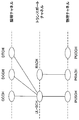
- FIGS. 1 and 2 are diagrams illustrating a channel configuration in EUTRA. As shown in FIGS. 1 and 2, these channels are classified into logical channels, transport channels, and physical channels.
- FIG. 1 shows a downlink channel
- FIG. 2 shows an uplink channel.
- the logical channel defines the type of data transmission service that is transmitted and received in a medium access control (MAC) layer.
- the transport channel defines what characteristics the data transmitted over the air interface has and how it is transmitted.
- a physical channel is a physical channel that carries a transport channel.
- the logical channel includes a broadcast control channel (BCCH: Broadcast Control Channel), a paging control channel (PCCH: Paging Control Channel), a common control channel (CCCH: Common Control Channel), a dedicated control channel (DCCH: Dedicated Control Channel), and a dedicated channel.
- BCCH Broadcast Control Channel
- PCCH Paging Control Channel
- CCCH Common Control Channel
- DCCH dedicated Control Channel
- a traffic channel DTCH: Dedicated Traffic Channel
- MCCH Multicast Control Channel
- MTCH Multicast Traffic Channel
- Transport channels include broadcast channel (BCH: Broadcast Channel), paging channel (PCH: Paging Channel), downlink shared channel (DL-SCH: Downlink Shared Channel), multicast channel (MCH: Multicast Channel), shared uplink A channel (UL-SCH: Uplink Shared Channel) and a random access channel (RACH: Random Access Channel) are included.
- BCH Broadcast Channel
- PCH Paging Channel
- DL-SCH Downlink Shared Channel
- MCH Multicast Channel
- shared uplink A channel UL-SCH: Uplink Shared Channel
- RACH Random Access Channel
- the physical channel includes a physical broadcast channel (PBCH), a physical downlink control channel (PDCCH), a physical downlink shared channel (PDSCH), a physical multicast channel (PMCH).
- PBCH physical broadcast channel
- PDCH physical downlink control channel
- PDSCH physical downlink shared channel
- PMCH physical multicast channel
- Physical Multicast Channel Physical Uplink Shared Channel
- PUSCH Physical Uplink Shared Channel
- PRACH Physical Random Access Channel
- Physical Uplink Control Channel PUCCH: Physical Uplink Control Channel
- PCFICH Physical-Control-Format-Indicator-Channel
- PHICH Physical-Hybrid-ARQ-Indicator-Channel
- the broadcast control channel is a downlink channel used for broadcasting system control information.
- the paging control channel is a downlink channel used for transmitting paging information, and is used when the network does not know the cell position of the mobile station apparatus.
- the common control channel is a channel used to transmit control information between the mobile station device and the network, and the mobile station device does not have a radio resource control (RRC) connection with the network. Used by.
- the dedicated control channel is a one-to-one (point-to-point) bidirectional channel and is a channel used for transmitting individual control information between the mobile station apparatus and the network.
- the dedicated control channel is used by a mobile station apparatus having an RRC connection.
- the dedicated traffic channel is a one-to-one bidirectional channel, is a channel dedicated to one mobile station apparatus, and is used for transferring user information (unicast data).
- the multicast control channel is a downlink channel used for transmitting MBMS control information from the network to the mobile station apparatus in a point-to-multipoint manner.
- MBMS Multimedia Broadcast Multicast Service
- MBMS service transmission methods include single-cell point-to-multipoint (SCPTM) transmission and multimedia broadcast multicast service single frequency network (MBSFN) transmission.
- SCPTM single-cell point-to-multipoint
- MBSFN multimedia broadcast multicast service single frequency network
- MBSFN transmission is a simultaneous transmission technique realized by transmitting waveforms (signals) that can be simultaneously identified from a plurality of cells.
- SCPTM transmission is a method of transmitting an MBMS service by one base station apparatus.
- the multicast control channel is a downlink channel used for transmitting MBMS control information from the network to the mobile station apparatus in a point-to-multipoint manner.
- the multicast control channel (MCCH) is used for one or a plurality of multicast traffic channels (MTCH).
- the multicast traffic channel (MTCH) is a downlink channel used to transmit traffic data (MBMS transmission data) from the network to the mobile station apparatus in a point-to-multipoint manner. Note that the multicast control channel (MCCH) and the multicast traffic channel (MTCH) are used only by the mobile station apparatus that receives MBMS.
- the broadcast channel needs to be broadcast to the entire cell in a fixed and predefined transmission format.
- DL-SCH downlink shared channel
- HARQ dynamic adaptive radio link control
- DRX discontinuous reception
- MBMS MBMS transmission
- DL-SCH downlink shared channel
- beamforming can be used, and dynamic resource allocation and quasi-static resource allocation are supported.
- the paging channel (PCH) supports DRX and needs to be broadcast to the entire cell.
- the paging channel (PCH) is mapped to a physical resource that is dynamically used for a traffic channel and other control channels, that is, a physical downlink shared channel (PDSCH).
- PDSCH physical downlink shared channel
- the multicast channel needs to be broadcast to the entire cell.
- quasi-static resource allocation such as MBSFN (MBMS Single Frequency Network) combining (Combining) for MBMS transmission from multiple cells and time frames using extended cyclic prefix (CP) Is supported.
- MBSFN MBMS Single Frequency Network
- CP extended cyclic prefix
- the uplink shared channel (UL-SCH) supports HARQ and dynamic adaptive radio link control.
- beam forming can be used in the uplink shared channel (UL-SCH). Dynamic resource allocation and semi-static resource allocation are supported.
- the random access channel (RACH) transmits limited control information and has a collision risk.
- the physical broadcast channel maps the broadcast channel (BCH) at intervals of 40 milliseconds.
- the 40 millisecond timing is blind detection (ie, no explicit signaling is provided for timing presentation).
- a subframe including a physical broadcast channel (PBCH) can be decoded only by the subframe (self-decodable), and is not divided into a plurality of times and transmitted.
- the physical downlink control channel includes downlink shared channel (PDSCH) resource allocation, hybrid automatic repeat request (HARQ) information for downlink data, and physical uplink shared channel (PUSCH) information.
- PDSCH downlink shared channel
- HARQ hybrid automatic repeat request
- PUSCH physical uplink shared channel
- the physical downlink shared channel is a channel used for transmitting downlink data or paging information.
- the physical multicast channel is a channel used for transmitting the multicast channel (MCH), and a downlink reference signal, an uplink reference signal, and a physical downlink synchronization signal are separately arranged.
- the physical uplink shared channel is a channel mainly used for transmitting uplink data (UL-SCH).
- the channel feedback report CQI, PMI, RI
- the HARQ acknowledgment ACK: Acknowledgement
- NACK Negative Acknowledgment
- the physical random access channel is a channel used for transmitting a random access preamble and has a guard time.
- the physical uplink control channel (PUCCH) transmits channel feedback report CFR, scheduling request (SR: Scheduling Request), HARQ for downlink transmission, acknowledgment (ACK: Acknowledgement) / negative response (NACK: Negative Acknowledgment), and the like. Is the channel used for.
- the physical control format indication channel (PCFICH) is a channel used to notify the mobile station apparatus of the number of OFDM symbols used for the physical downlink control channel (PDCCH), and is transmitted in each subframe.
- the physical hybrid automatic retransmission request instruction channel (PHICH) is a channel used for transmitting HARQ ACK / NACK for uplink transmission.
- mapping between the transport channel and the physical channel is performed as follows.
- the broadcast channel (BCH) is mapped to the physical broadcast channel (PBCH).
- the multicast channel (MCH) is mapped to the physical multicast channel (PMCH).
- the paging channel (PCH) and the downlink shared channel (DL-SCH) are mapped to the physical downlink shared channel (PDSCH).
- the physical downlink control channel (PDCCH), the physical hybrid automatic repeat request instruction channel (PHICH), and the physical control format instruction channel (PCFICH) are used alone.
- the transport channel and the physical channel are mapped as follows.
- the uplink shared channel (UL-SCH) is mapped to the physical uplink shared channel (PUSCH).
- the random access channel (RACH) is mapped to the physical random access channel (PRACH).
- the physical uplink control channel (PUCCH) is used as a physical channel alone.
- mapping between logical channels and transport channels is performed as follows.
- the paging control channel (PCCH) is mapped to the downlink shared channel (DL-SCH).
- the broadcast control channel (BCCH) is mapped to the broadcast channel (BCH) and the downlink shared channel (DL-SCH).
- the common control channel (CCCH), dedicated control channel (DCCH), and dedicated traffic channel (DTCH) are mapped to the downlink shared channel (DL-SCH).
- the multicast control channel (MCCH) is mapped to the downlink shared channel (DL-SCH) and the multicast channel (MCH).
- the multicast traffic channel (MTCH) is mapped to the downlink shared channel (DL-SCH) and the multicast channel (MCH).
- mapping from the multicast control channel (MCCH) and the multicast traffic channel (MTCH) to the multicast channel (MCH) is performed at the time of MBSFN transmission, while this mapping is performed at the downlink shared channel (DL-SCH) at the time of SCPTM transmission.
- the logical channel and the transport channel are mapped in the uplink as follows.
- the common control channel (CCCH), dedicated control channel (DCCH), and dedicated traffic channel (DTCH) are mapped to the uplink shared channel (UL-SCH).
- the random access channel (RACH) is not mapped with the logical channel.
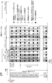
- FIG. 3 shows a downlink frame configuration
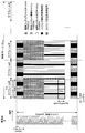
- FIG. 4 shows an uplink frame configuration
- a radio frame identified by a system frame number (SFN) is composed of 10 milliseconds.
- One subframe is composed of 1 millisecond, and the radio frame includes 10 subframes.
- a subframe is divided into two slots.
- normal CP normal CP
- the downlink slot is composed of seven OFDM symbols
- the uplink slot is composed of seven SC-FDMA (Single Carrier-Frequency Division Multiple Multiple Access) symbols. Is done.
- extended CP also referred to as “long CP” or “extended CP”
- the downlink slot is composed of 6 OFDM symbols
- the uplink slot is 6 SC-FDMA symbols. Consists of.
- one slot is divided into a plurality of blocks in the frequency direction.
- One physical resource block (PRB: Physical Resource Block) is configured with twelve 15 kHz subcarriers as units in the frequency direction.
- the number of physical resource blocks (PRB) is supported from 6 to 110 depending on the system bandwidth.
- Downlink and uplink resource allocation is performed in subframe units in the time direction and in physical resource block (PRB) units in the frequency direction. That is, two slots in a subframe are allocated with one resource allocation signal.
- a unit composed of a subcarrier and an OFDM symbol or a subcarrier and an SC-FDMA symbol is called a resource element.
- a modulation symbol or the like is mapped to each resource element in the resource mapping process in the physical layer.
- a 24-bit cyclic redundancy check (CRC: Cyclic Redundancy Check) is assigned to the physical downlink shared channel (PDSCH), channel coding (transmission path coding), and physical layer HARQ. Processing, channel interleaving, scrambling, modulation (QPSK, 16QAM, 64QAM), layer mapping, precoding, resource mapping, antenna mapping, and the like are performed.
- CRC Cyclic Redundancy Check
- 24-bit CRC is assigned to the physical uplink shared channel (PUSCH), channel coding (transmission path coding), physical layer HARQ processing, scrambling, modulation ( QPSK, 16QAM, 64QAM), resource mapping, antenna mapping, and the like are performed.
- the physical downlink control channel (PDCCH), the physical hybrid automatic repeat request indication channel (PHICH), and the physical control format indication channel (PCFICH) are arranged below the first 3 OFDM symbols.
- a transport format for the downlink shared channel (DL-SCH) and paging channel (PCH) (which defines modulation scheme, coding scheme, transport block size, etc.) and resource allocation.
- HARQ information is transmitted.
- the transport format (modulation scheme, coding scheme, transport block size, etc.), resource allocation, and HARQ information for the uplink shared channel (UL-SCH) are defined.
- Sent A plurality of physical downlink control channels (PDCCH) are supported, and the mobile station apparatus monitors a set of physical downlink control channels (PDCCH).
- the physical downlink shared channel (PDSCH) allocated by the physical downlink control channel (PDCCH) is mapped to the same subframe as the physical downlink control channel (PDCCH).
- the physical uplink shared channel (PUSCH) allocated by the physical downlink control channel (PDCCH) is mapped to a subframe at a predetermined position. For example, when the downlink subframe number of the physical downlink control channel (PDCCH) is N, it is mapped to the N + 4th uplink subframe.
- the mobile station apparatus is specified using 16-bit MAC layer identification information (MAC ID). That is, this 16-bit MAC layer identification information (MAC ID) is included in the physical downlink control channel (PDCCH).
- MAC ID 16-bit MAC layer identification information
- the downlink reference signal (downlink pilot channel) used for downlink state measurement and downlink data demodulation is arranged in the first, second, and third from the back of each slot.
- an uplink demodulation reference signal (a demodulation pilot (DRS: Demodulation Reference Signal)) used for demodulating the physical uplink shared channel (PUSCH) is transmitted in the fourth SC-FDMA symbol of each slot.
- an uplink measurement reference signal (scheduling pilot (SRS: Sounding Reference Signal)) used for uplink state measurement is transmitted in the first SC-FDMA symbol of the subframe.
- the reference signal for demodulation of the uplink control channel (PUCCH) is defined for each uplink control channel format, and the 3rd and 4th and 5th of each slot or the 2nd and 6th SC-FDMA symbols of each slot Sent by.
- the physical broadcast channel (PBCH) and the downlink synchronization signal are arranged in a band corresponding to the center 6 physical resource blocks in the system band.
- the physical downlink synchronization signal is transmitted in the sixth and seventh OFDM symbols of each slot of the first (subframe # 0) and fifth (subframe # 4) subframes.
- the physical broadcast channel (PBCH) is the fourth slot of the first slot (slot # 0) of the first subframe (subframe # 0), the fifth OFDM symbol, and the first slot (slot # 1) of 1
- the second and second OFDM symbols are transmitted.
- the random access channel is configured with a bandwidth of six physical resource blocks in the frequency direction and one subframe in the time direction.
- Request from mobile station device to base station device for various reasons uplink resource request, uplink synchronization request, downlink data transmission resumption request, handover request, connection setting request, reconnection request, MBMS service request, etc.) Sent to do.
- the uplink control channel (PUCCH) is arranged at both ends of the system band and is configured in units of physical resource blocks. Frequency hopping is performed so that both ends of the system band are alternately used between slots.
- the communication system includes a base station device 100 and a mobile station device 200.
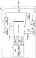
- FIG. 5 is a block diagram illustrating a schematic configuration of the base station apparatus according to the present embodiment.
- the base station apparatus 100 includes a data control unit 101, an OFDM modulation unit 102, a radio unit 103, a scheduling unit 104, a channel estimation unit 105, a DFT-Spread-OFDM (DFT-S -OFDM) demodulator 106, data extractor 107, and higher layer 108.
- DFT-S -OFDM DFT-Spread-OFDM
- the radio unit 103, the scheduling unit 104, the channel estimation unit 105, the DFT-Spread-OFDM (DFT-S-OFDM) demodulation unit 106, the data extraction unit 107, and the upper layer 108 constitute a reception unit, and the data control unit 101 , OFDM modulation section 102, radio section 103, scheduling section 104, and higher layer 108 constitute a transmission section.
- DFT-S-OFDM DFT-Spread-OFDM
- the radio unit 103, the channel estimation unit 105, the DFT-Spread-OFDM (DFT-S-OFDM) demodulation unit 106, and the data extraction unit 107 perform processing of the uplink physical layer.
- the radio unit 103, the DFT-Spread-OFDM (DFT-S-OFDM) demodulation unit 106, and the data extraction unit 107 perform processing on the downlink physical layer.
- the data control unit 101 receives the transport channel and scheduling information from the scheduling unit 104. Signals and channels generated in the transport channel and the physical layer are mapped to physical channels based on the scheduling information input from the scheduling unit 104. Each piece of data mapped as described above is output to OFDM modulation section 102.
- the OFDM modulation unit 102 performs scheduling information (downlink physical resource block PRB (Physical Resource Block) allocation information (for example, physical resource blocks such as frequency and time) on the data input from the data control unit 101). Position information), and modulation and coding schemes corresponding to each PRB (including 16QAM modulation, 2/3 coding rate, etc.), encoding, data modulation, serial / parallel conversion of input signals, OFDM signal processing such as IFFT (InverseInFourier Transform) processing, CP (Cyclic Prefix) insertion, and filtering is performed to generate an OFDM signal and output it to the radio section 103.
- PRB Physical Resource Block allocation information
- Position information position information
- modulation and coding schemes corresponding to each PRB including 16QAM modulation, 2/3 coding rate, etc.
- OFDM signal processing such as IFFT (InverseInFourier Transform) processing, CP (Cyclic Prefix) insertion, and filtering is performed to generate an OFDM signal and output it to the
- the radio unit 103 up-converts the modulation data input from the OFDM modulation unit 102 to a radio frequency to generate a radio signal, and transmits the radio signal to the mobile station apparatus 200 via an antenna (not shown). Also, the radio section 103 receives an uplink radio signal from the mobile station apparatus 200 via an antenna (not shown), down-converts it into a baseband signal, and converts the received data to the channel estimation section 105 and the DFT. Output to the S-OFDM demodulator 106.
- the scheduling unit 104 performs processing of a medium access control (MAC: Medium Access Control) layer.
- the scheduling unit 104 performs mapping between logical channels and transport channels, downlink and uplink scheduling (HARQ processing, selection of transport format, etc.), and the like.
- the scheduling unit 104 receives uplink feedback information (downlink channel feedback information (channel state information (channel quality, number of streams, precoding information, etc.)) received from the mobile station apparatus 200, ACK / NACK feedback information for downlink data), PRB information available for each mobile station apparatus, buffer status, downlink for modulating each data based on scheduling information input from higher layer 108, etc.
- Transport format (transmission form) physical resource block allocation and modulation scheme and encoding scheme, etc. selection processing and HARQ retransmission control are performed.
- the scheduling information used for downlink scheduling is output to the data control unit 101.
- the scheduling unit 104 estimates the uplink channel state (radio channel state) output from the channel estimation unit 105, the resource allocation request from the mobile station device 200, and each mobile station device 200. Based on the available PRB information, scheduling information input from the higher layer 108, and the like, an uplink transport format (transmission form) for modulating each data (physical resource block allocation and modulation scheme and code) Process). Scheduling information used for uplink scheduling is output to the data control unit 101.
- the scheduling unit 104 maps the downlink logical channel input from the higher layer 108 to the transport channel, and outputs it to the data control unit 101.
- the scheduling unit 104 processes the control data and the transport channel acquired in the uplink input from the data extraction unit 107 as necessary, maps them to the uplink logical channel, and outputs them to the upper layer 108. To do.
- the channel estimation unit 105 estimates an uplink channel state from an uplink demodulation reference signal (DRS: Demodulation Reference Signal) for demodulation of the uplink data, and the estimation result is used as a DFT-S-OFDM demodulation unit 106. Output to. Further, in order to perform uplink scheduling, an uplink channel state is estimated from an uplink measurement reference signal (SRS: Sounding Reference Signal), and the estimation result is output to the scheduling section 104.
- DRS Demodulation Reference Signal
- SRS Sounding Reference Signal
- the uplink communication scheme is assumed to be a single carrier scheme such as DFT-S-OFDM, but a multicarrier scheme such as the OFDM scheme may be used.
- the DFT-S-OFDM demodulation unit 106 performs DFT conversion, subcarrier mapping, IFFT conversion on the modulation data input from the radio unit 103 based on the uplink channel state estimation result input from the channel estimation unit 105. Then, DFT-S-OFDM signal processing such as filtering is performed, demodulation processing is performed, and the result is output to the data extraction unit 107.
- the data extraction unit 107 confirms the correctness of the data input from the DFT-S-OFDM demodulation unit 106 and outputs a confirmation result (positive signal ACK / negative signal NACK) to the scheduling unit 104. Also, the data extraction unit 107 separates the data input from the DFT-S-OFDM demodulation unit 106 into a transport channel and physical layer control data, and outputs them to the scheduling unit 104.
- the separated control data includes uplink feedback information (downlink channel feedback report CFR, ACK / NACK feedback information for downlink data) notified from the mobile station apparatus 200, and the like.
- the upper layer 108 performs processing of a packet data integration protocol (PDCP: Packet Data Convergence Protocol) layer, a radio link control (RLC: Radio Link Control) layer, and a radio resource control (RRC: Radio Resource Control) layer.
- PDCP Packet Data Convergence Protocol
- RLC Radio Link Control
- RRC Radio Resource Control
- the upper layer 108 has a radio resource control unit 109 (also referred to as a control unit).
- the radio resource control unit 109 manages various setting information, system information, paging control, communication state management of each mobile station device, mobility management such as handover, management of buffer status for each mobile station device, Management of unicast and multicast bearer connection settings, management of mobile station identifiers (UEID), and the like are performed.
- UEID mobile station identifiers
- FIG. 6 is a block diagram showing a schematic configuration of the mobile station apparatus according to this embodiment.
- mobile station apparatus 200 includes data control section 201, DFT-S-OFDM modulation section 202, radio section 203, scheduling section 204, channel estimation section 205, OFDM demodulation section 206, The data extraction unit 207 and the upper layer 208 are included.
- the data control unit 201, DFT-S-OFDM modulation unit 202, radio unit 203, scheduling unit 204, and higher layer 208 constitute a transmission unit, and the radio unit 203, scheduling unit 204, channel estimation unit 205, OFDM demodulation
- the unit 206, the data extraction unit 207, and the higher layer 208 constitute a reception unit.
- the scheduling unit 204 constitutes a selection unit.
- the data control unit 201, the DFT-S-OFDM modulation unit 202, and the radio unit 203 perform processing on the uplink physical layer.
- the radio unit 203, the channel estimation unit 205, the OFDM demodulation unit 206, and the data extraction unit 207 perform downlink physical layer processing.
- the data control unit 201 receives the transport channel and scheduling information from the scheduling unit 204. Signals and channels generated in the transport channel and the physical layer are mapped to physical channels based on scheduling information input from the scheduling unit 204. Each piece of data mapped in this way is output to the DFT-S-OFDM modulation unit 202.
- the DFT-S-OFDM modulation unit 202 performs data modulation, DFT (Discrete Fourier Transform) processing, subcarrier mapping, IFFT (Inverse Fast Fourier Transform) processing, CP insertion, filtering on the data input from the data control unit 201.
- DFT-S-OFDM signal processing such as the above is performed to generate a DFT-S-OFDM signal and output it to the radio section 203.
- the uplink communication scheme is assumed to be a single carrier scheme such as DFT-S-OFDM, but a multicarrier scheme such as the OFDM scheme may be used instead.
- Radio section 203 up-converts the modulation data input from DFT-S-OFDM modulation section 202 to a radio frequency, generates a radio signal, and transmits the radio signal to base station apparatus 100 via an antenna (not shown). .
- Radio section 203 receives a radio signal modulated with downlink data from base station apparatus 100 via an antenna (not shown), down-converts it into a baseband signal, Output to channel estimation section 205 and OFDM demodulation section 206.
- the scheduling unit 204 performs processing of a medium access control (MAC: Medium Access Control) layer.
- the scheduling unit 104 performs mapping between logical channels and transport channels, and downlink and uplink scheduling (HARQ processing, transport format selection, etc.).
- HARQ processing transport format selection, etc.
- the scheduling unit 204 performs transport channel and physical signal and physical channel reception control based on scheduling information (transport format and HARQ retransmission information) from the base station apparatus 100 and the upper layer 208, and the like.
- HARQ retransmission control is performed.
- the scheduling unit 204 receives the uplink buffer status input from the higher layer 208 and uplink scheduling information from the base station apparatus 100 input from the data extraction unit 207 (transport format and HARQ retransmission). Information) and scheduling information input from the higher layer 208, etc., and performs scheduling processing for mapping the uplink logical channel input from the higher layer 208 to the transport channel. Note that the information notified from the base station apparatus 100 is used for the uplink transport format. The scheduling information is output to the data control unit 201.
- the scheduling unit 204 maps the uplink logical channel input from the higher layer 208 to the transport channel, and outputs it to the data control unit 201.
- the scheduling unit 204 also outputs the downlink channel feedback report CFR (channel state information) input from the channel estimation unit 205 and the CRC confirmation result input from the data extraction unit 207 to the data control unit 201.
- the scheduling unit 204 processes the control data and the transport channel acquired in the downlink input from the data extraction unit 207 as necessary, maps them to the downlink logical channel, and outputs them to the upper layer 208. To do.
- the channel estimation unit 205 estimates the downlink channel state from the downlink reference signal (RS) and demodulates the downlink data, and outputs the estimation result to the OFDM demodulation unit 206. Further, the channel estimation unit 205 estimates the downlink channel state from the downlink reference signal (RS) in order to notify the base station apparatus 100 of the estimation result of the downlink channel state (radio channel state), This estimation result is converted into downlink channel state feedback information (channel quality information, etc.) and output to scheduling section 204.
- RS downlink reference signal
- OFDM demodulation section 206 Based on the downlink channel state estimation result input from channel estimation section 205, OFDM demodulation section 206 performs OFDM demodulation processing on the modulated data input from radio section 203 and outputs the result to data extraction section 207. To do.
- the data extracting unit 207 performs CRC on the data input from the OFDM demodulating unit 206, confirms correctness and outputs a confirmation result (ACK / NACK feedback information) to the scheduling unit 204. Further, the data extraction unit 207 separates the data input from the OFDM demodulation unit 206 into transport channel and physical layer control data, and outputs the data to the scheduling unit 204.
- the separated control data includes scheduling information such as downlink or uplink resource allocation and uplink HARQ control information.
- the search space (also referred to as a search region) of the physical downlink control signal (PDCCH) is decoded to extract downlink or uplink resource allocations addressed to the own station.
- the upper layer 208 performs processing of a packet data integration protocol (PDCP: Packet Data Convergence Protocol) layer, a radio link control (RLC: Radio Link Control) layer, and a radio resource control (RRC: Radio Resource Control) layer.
- PDCP Packet Data Convergence Protocol
- RLC Radio Link Control
- RRC Radio Resource Control
- the upper layer 208 has a radio resource control unit 209 (also referred to as a control unit).
- the radio resource control unit 209 manages various setting information, system information, paging control, local station communication status management, mobility management such as handover, buffer status management, unicast and multicast bearer connection setting. Management and management of mobile station identifier (UEID).
- UEID mobile station identifier
- the mobile station apparatus transmits the channel feedback report CFR continuously (persistently) on the allocated uplink resource (physical uplink shared channel (PUSCH)) or temporarily allocated (oneshot) Whether to transmit using an uplink resource (physical uplink shared channel (PUSCH)) is determined according to information included in a physical downlink control signal (PDCCH) for performing uplink resource allocation.
- PUSCH physical uplink shared channel
- PDCCH physical downlink control signal
- a physical downlink control signal (PDCCH) for performing continuous uplink resource allocation includes information requesting a channel feedback report CFR
- the mobile station apparatus transmits uplink data (uplink shared channel: UL- SCH) and channel feedback report CFR are transmitted on a persistently allocated physical uplink shared channel (PUSCH), and the physical downlink control signal (PDCCH) does not include information requesting the channel feedback report CFR Transmits uplink data on a physical uplink shared channel (PUSCH) that is continuously assigned.
- uplink shared channel: UL- SCH uplink shared channel
- PUSCH physical downlink control signal
- the mobile station apparatus determines whether the MAC ID included in the physical downlink control signal (PDCCH) includes a cell radio network temporary identifier (C-RNTI: Cell :-Radio Network Temporary Identity) that is the mobile station identifier of the mobile station. Then, it is determined whether the control signal is addressed to the own station.
- the MAC ID may be identified as a CRC of the physical downlink control signal (PDCCH), or may be identified by a scramble code of the physical downlink control signal (PDCCH).
- the physical downlink control signal (PDCCH) is identified as an uplink transmission permission signal or downlink resource allocation by its bit size or flag.
- the uplink transmission permission signal includes a channel feedback report request.
- a request is made to transmit only the channel feedback report CFR (ACK / NACK for downlink data may be included) without including the uplink data (UL-SCH) in the physical downlink control signal (PDCCH).
- ACK / NACK for downlink data may be included
- UL-SCH uplink data
- PDCCH physical downlink control signal
- a method of including a signal to be performed will be described.
- a part of the transport format is reserved in advance and a specific information sequence is included in the physical downlink control signal (PDCCH)
- the 5-bit MCS value is 11111, etc.
- it is instructed to simply include the 1-bit signal in the physical downlink control signal (PDCCH) and request to transmit only the channel feedback report CFR. .
- This is called a channel feedback report dedicated transmission request.
- the base station apparatus is a cell radio that is a mobile station identifier indicating that the mobile station apparatus is for activation of persistent scheduling, in addition to the cell radio network temporary identifier (C-RNTI) used for normal dynamic scheduling.
- C-RNTI cell radio network temporary identifier
- a special scrambling code for activation of persistent scheduling is applied to the physical downlink control signal (PDCCH).
- Other information included in the physical downlink control signal (PDCCH) is the same for persistent scheduling (or periodic channel feedback) and dynamic scheduling.
- transport format, resource allocation (PRB allocation), HARQ information, channel feedback report request, etc. are included. That is, by introducing a mobile station identifier indicating activation of persistent scheduling (or periodic channel feedback), a normal physical downlink control signal (for regular scheduling (or periodic channel feedback) can be used. PDCCH) can be used. Further, when persistent scheduling and periodic channel feedback are set simultaneously, the same cell radio network temporary identifier (C-RNTI) is used. This makes it possible to share persistent scheduling and periodic channel feedback mechanisms. However, separate cell radio network temporary identifiers (C-RNTIs) may be assigned for persistent scheduling and periodic channel feedback.
- C-RNTI separate cell radio network temporary identifiers
- the physical downlink control signal (PDCCH) is composed of a set of a plurality of resource element groups, and there are a plurality of corresponding resource element groups, and the number of resource elements included in the physical downlink control signal (PDCCH). There are also a plurality of coding rates that are variable.
- the mobile station apparatus decodes all the candidates for placement of the physical downlink control signal (PDCCH), includes the mobile station identification information of the local station, and succeeds in CRC, so that the physical downlink addressed to the mobile station is transmitted.
- the link control signal (PDCCH) is specified and decoded. This process is called blind decoding.
- a physical downlink control signal (PDCCH) search space (to be decoded) is output from a hash function based on the mobile station identifier temporary identifier (C-RNTI). Resource group).
- the input of the hash function always includes a cell radio network temporary identifier (C-RNTI) for dynamic scheduling, that is, a cell radio network temporary identifier (C-RNTI) that is normally always assigned to a mobile station apparatus in communication. Is used.
- the mobile station apparatus When the mobile station apparatus holds a plurality of mobile station identifiers (here, the persistent scheduling cell radio network temporary identifier (C-RNTI) and / or the cell radio network temporary identifier for periodic channel feedback (C-RNTI)) And / or the mobile radio station temporary identifier for dynamic scheduling), the mobile station apparatus transmits a physical downlink control signal (PDCCH) corresponding to one mobile station identifier (here, the mobile radio network temporary identifier for dynamic scheduling). A plurality of mobile station identifiers are searched in the search area.
- C-RNTI the persistent scheduling cell radio network temporary identifier
- C-RNTI cell radio network temporary identifier for periodic channel feedback
- PDCCH physical downlink control signal
- the base station device When a plurality of mobile station identifiers are allocated to the mobile station device, the base station device includes physical downlink identifiers including the respective mobile station identifiers in a physical downlink control signal (PDCCH) search area corresponding to one mobile station identifier.
- a control signal (PDCCH) is arranged.
- the mobile station apparatus maintains a physical downlink control signal (PDCCH) search space (also referred to as a search area), while maintaining another cell radio network temporary identifier for persistent scheduling or periodic channel feedback (C -RNTI) is searched, and the processing is reduced.
- PDCCH physical downlink control signal
- C -RNTI periodic channel feedback
- the mobile station apparatus uses a physical downlink control signal (PDCCH) used for scheduling of broadcast information, random access response, and the like in order to limit the search space for the physical downlink control signal (PDCCH).
- PDCH physical downlink control signal
- the common search area is a search area in which all mobile station devices must always search for the physical downlink control signal (PDCCH) separately from the search area limited by the temporary scheduling cell dynamic network identifier.
- the mobile station apparatus searches for a mobile station identifier other than the dynamic scheduling cell radio network temporary identifier
- the persistent scheduling cell radio network temporary identifier (C-RNTI) and / or the periodic channel is used in this common search area.
- the cell radio network temporary identifier (C-RNTI) for feedback is searched.
- the base station apparatus includes a physical downlink control signal (C-RNTI) and / or a physical downlink control signal (C-RNTI) for periodic channel feedback that includes a persistent scheduling cell radio network temporary identifier (C-RNTI) in a common search area. PDCCH).
- C-RNTI physical downlink control signal
- C-RNTI physical downlink control signal
- PDCCH physical downlink control signal
- the mobile station apparatus maintains a search space (also referred to as a search area) of the physical downlink control signal (PDCCH), while maintaining another cell radio network temporary identifier (C for use in persistent scheduling or periodic channel feedback).
- a search space also referred to as a search area
- C cell radio network temporary identifier
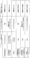
- FIG. 7 is a diagram illustrating an example of operation of the mobile station apparatus according to the type of the physical downlink control signal (PDCCH).
- the operation shown in FIG. 7 is controlled in cooperation with the physical layer and the MAC layer of the mobile station apparatus.
- a dedicated request for channel feedback report is set in the physical downlink control signal for dynamic use (PDCCH)
- only the channel feedback report is aperiodically shot with the designated PUSCH (one transmission, or To one HARQ process).
- the uplink data (UL-SCH) and the channel feedback report are aperiodically set to one shot using the designated PUSCH. Send.
- the uplink data (UL-SCH) is aperiodically transmitted on the designated PUSCH. Send to shot.
- a dedicated channel feedback report transmission request is set in the persistent (or periodic channel feedback) physical downlink control signal (PDCCH)
- PDCCH physical downlink control signal
- the feedback period at this time is a transmission period of the periodic channel feedback report set by RRC signaling.
- uplink data (UL-SCH) and channel feedback report are specified. Transmit periodically and continuously on PUSCH.
- persistent scheduling of uplink data and periodic channel feedback report are set simultaneously.
- the feedback cycle at this time is a persistent scheduling cycle of uplink data set by RRC signaling.
- the uplink data (UL-SCH) is specified. Periodically and continuously on the PUSCH.
- the feedback cycle at this time is a persistent scheduling cycle of uplink data set by RRC signaling.
- an uplink grant of “no uplink resource allocation” is transmitted using a physical downlink control signal (PDCCH).
- PDCCH physical downlink control signal
- PDCCH physical downlink control signal
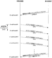
- FIG. 8 is a diagram illustrating another example of the operation of the mobile station apparatus according to the type of the physical downlink control signal (PDCCH).
- the channel feedback report request is not set in the dynamic physical downlink control signal (PDCCH) and the channel feedback report dedicated transmission request is set, only the channel feedback report is periodically transmitted with the specified PUSCH.
- Send persistently to The feedback period at this time is a transmission period of the periodic channel feedback report set by RRC signaling. This makes it possible to activate the periodic channel feedback report without using the persistent physical downlink control signal (PDCCH).
- the channel feedback report request is set in the dynamic physical downlink control signal (PDCCH) and the channel feedback report dedicated transmission request is not set
- the uplink data (UL-SCH) and the channel feedback report are Transmit to one shot aperiodically on the designated PUSCH.
- both a channel feedback report request and a channel feedback report dedicated request are set in the dynamic physical downlink control signal (PDCCH)
- only the channel feedback report is transmitted aperiodically on the designated PUSCH. .
- the uplink data (UL-SCH) is aperiodically transmitted on the designated PUSCH. Send to shot.
- the channel feedback report request is not set in the persistent (or periodic channel feedback) physical downlink control signal (PDCCH) and the channel feedback report dedicated transmission request is set, physical downlink control is performed.
- the signal (PDCCH) is used for other purposes.
- uplink data (UL -SCH) and channel feedback reports are sent periodically and continuously on the designated PUSCH.
- persistent scheduling of uplink data (UL-SCH) and periodic channel feedback report are set simultaneously.
- the feedback period at this time is a persistent scheduling period of uplink data (UL-SCH) set by RRC signaling.
- the persistent scheduling period of uplink data (UL-SCH) set by RRC signaling and the transmission period of the periodic channel feedback report are applied simultaneously. Accordingly, the persistent scheduling period of the uplink data (UL-SCH) and the periodic channel feedback report can be simultaneously activated by a single physical downlink control signal (PDCCH).
- PDCH physical downlink control signal
- a persistent (or periodic channel feedback) physical downlink control signal (PDCCH) is configured with both a channel feedback report request and a dedicated channel feedback report transmission request, only the channel feedback report is sent to the specified PUSCH.
- the feedback period at this time is a transmission period of the periodic channel feedback report set by RRC signaling.
- the uplink data (UL-SCH) is specified. Periodically and continuously on the PUSCH.
- the feedback cycle at this time is a persistent scheduling cycle of uplink data set by RRC signaling.
- an uplink grant of “no uplink resource allocation” is transmitted using a physical downlink control signal (PDCCH).
- PDCCH physical downlink control signal
- the channel feedback report request is not set in the physical physical downlink control signal (PDCCH), “no uplink resource allocation” and the channel feedback report dedicated transmission request is set, the periodic channel feedback report Just stop.
- PDCCH physical physical downlink control signal
- the persistent (or periodic channel feedback) physical downlink control signal has no channel feedback report request set, “no uplink resource allocation” and a channel feedback report dedicated transmission request are set. If it is, stop the persistent scheduling of the uplink data in use or the periodic channel feedback report. When both are used, the uplink data persistent scheduling and periodic channel feedback report are stopped simultaneously.
- PDCCH Persistent (or periodic channel feedback) physical downlink control signal
- PDCCH physical downlink control signal
- FIG. 9 is a diagram illustrating another example of the operation of the mobile station apparatus according to the type of the physical downlink control signal (PDCCH).
- PDCCH physical downlink control signal
- C-RNTIs separate cell radio network temporary identifiers
- the operation shown in FIG. 9 is controlled in cooperation with the physical layer and the MAC layer of the mobile station apparatus.
- a dedicated request for channel feedback report is set in the physical downlink control signal for dynamic use (PDCCH)
- only the channel feedback report is aperiodically shot with the designated PUSCH (one transmission, or To one HARQ process).
- the uplink data (UL-SCH) and the channel feedback report are aperiodically set to one shot using the designated PUSCH. Send.
- the uplink data (UL-SCH) is aperiodically transmitted on the designated PUSCH. Send to shot.
- the uplink data (UL-SCH) and the channel feedback report are periodically and continuously transmitted on the designated PUSCH. Send.
- persistent scheduling of uplink data and periodic channel feedback report are set simultaneously.
- the feedback cycle at this time is a persistent scheduling cycle of uplink data set by RRC signaling.
- the uplink data (UL-SCH) is periodically maintained on the designated PUSCH.
- the feedback cycle at this time is a persistent scheduling cycle of uplink data set by RRC signaling.
- the feedback period at this time is a transmission period of the periodic channel feedback report set by RRC signaling.
- an uplink grant of “no uplink resource allocation” is transmitted using a physical downlink control signal (PDCCH).
- PDCCH physical downlink control signal
- the PUSCH of the subframe at the timing corresponding to the uplink transmission permission signal is used for the periodic channel feedback report and the PUSCH time timing of the uplink persistent scheduling. Thereby, it is possible to dynamically allocate resources at high speed.
- the subframe offset may be set by RRC signaling.
- a subframe offset of the periodic channel feedback report and a subframe offset of persistent scheduling of uplink data are set.
- the PUSCH time timing of the periodic channel feedback report and the uplink persistent scheduling is specified by the RRC signaling. This makes it possible to allocate resources more robustly.
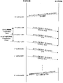
- FIG. 10 is a diagram illustrating an example of signal transmission / reception between the mobile station apparatus and the base station apparatus corresponding to the dynamic physical downlink control signal (PDCCH) illustrated in FIG.
- the base station apparatus transmits a dynamic uplink grant addressed to the mobile station apparatus using a physical downlink control signal (PDCCH).
- This uplink grant includes a dedicated channel feedback report request.
- the mobile station apparatus that has received the dedicated channel feedback report request in D-subframe # 2 performs uplink transmission on the PUSCH including only the channel feedback report CFR in U-subframe # 6.
- the base station apparatus transmits a dynamic uplink grant addressed to the mobile station apparatus using a physical downlink control signal (PDCCH) in D-subframe # 8.
- This uplink grant includes a channel feedback report request.
- the mobile station apparatus that has received the channel feedback report request in D-subframe # 8 performs uplink transmission on the PUSCH including the channel feedback report CFR and uplink data (UL-SCH) in U-subframe # 12.
- the base station apparatus transmits a dynamic uplink grant addressed to the mobile station apparatus using a physical downlink control signal (PDCCH) in D-subframe # 14.
- This uplink grant does not include a channel feedback report request or a channel feedback report dedicated request.
- the mobile station apparatus that has received the uplink grant at D-subframe # 14 performs uplink transmission on the PUSCH that does not include the channel feedback report CFR at U-subframe # 18.
- FIG. 11 shows the signals of the mobile station apparatus and the base station apparatus corresponding to the case where the channel feedback report dedicated request is specified in the persistent (or periodic channel feedback) physical downlink control signal (PDCCH) shown in FIG. It is a figure which shows the example of transmission / reception of.
- a mobile station apparatus and a base station apparatus perform a setting for a periodic channel feedback report by transmitting / receiving RRC signaling in advance.
- This setting includes a cell radio network temporary identifier (C-RNTI) which is a mobile station identifier indicating that the periodic channel feedback report is activated, and a reporting format of the periodic feedback report (broadband report, mobile station selection). Subband report, base station selection subband report, etc.), feedback period (transmission interval), and the like.
- C-RNTI cell radio network temporary identifier
- the base station apparatus transmits an uplink grant for periodic channel feedback addressed to the mobile station apparatus using a physical downlink control signal (PDCCH).
- This uplink grant includes a dedicated channel feedback report request.
- the mobile station apparatus that has received the channel feedback report dedicated request in D-subframe # 2 receives a 2-subframe interval from U-subframe # 6 (assuming that a transmission interval of 2 subframes (2 ms) is set by RRC signaling) Uplink transmission is performed on the PUSCH including only the channel feedback report CFR.
- the base station apparatus transmits an uplink grant for periodic channel feedback of “no uplink resource allocation” using a physical downlink control signal (PDCCH).
- PDCCH physical downlink control signal
- “no uplink resource allocation” is identified by the fact that the resource allocation information included in the uplink grant has a predetermined special value.
- the mobile station apparatus that has received the uplink grant for periodic channel feedback of “No uplink resource allocation” in D-subframe # 18 stops the periodic channel feedback.
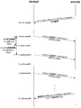
- FIG. 12 shows the signals of the mobile station apparatus and the base station apparatus corresponding to the case where the channel feedback report request is designated in the persistent (or periodic channel feedback) physical downlink control signal (PDCCH) shown in FIG. It is a figure which shows the example of transmission / reception.
- a mobile station apparatus and a base station apparatus perform a setting for a periodic channel feedback report by transmitting / receiving RRC signaling in advance. This setting includes the reporting format of the periodic feedback report (broadband report, mobile station selection subband report, base station selection subband report, etc.), feedback period (transmission interval), and the like.
- the mobile station apparatus and the base station apparatus perform settings for persistent scheduling in advance by transmitting and receiving RRC signaling.
- This setting includes a cell radio network temporary identifier (C-RNTI) that is a mobile station identifier indicating that the persistent scheduling is activated, a period (transmission interval), and the like.
- C-RNTI cell radio network temporary identifier
- a channel feedback report period of 5 subframes (5 ms) and a persistent scheduling period of 10 subframes (10 ms) are set by RRC signaling.
- the base station apparatus transmits a persistent uplink grant addressed to the mobile station apparatus using a physical downlink control signal (PDCCH) in D-subframe # 2.
- This uplink grant includes a channel feedback report request.
- the mobile station apparatus that has received the channel feedback report request at D-subframe # 2 only receives the channel feedback report CFR at 10 subframe intervals from U-subframe # 11, and the channel feedback report CFR at 10 subframe intervals from U-subframe # 6.
- the base station apparatus transmits a persistent uplink grant of “no uplink resource allocation” using a physical downlink control signal (PDCCH).
- PDCCH physical downlink control signal
- the mobile station apparatus that has received the persistent uplink grant of “no uplink resource allocation” in D-subframe # 30, receives periodic channel feedback and / or uplink data (UL-SCH) in the persistent resource. Stop sending. Which to stop is included in the persistent uplink grant. It is determined by a combination of a channel feedback report request and a dedicated channel feedback report request and “no uplink resource allocation”.
- FIG. 13 shows the signals of the mobile station apparatus and the base station apparatus corresponding to the case where the channel feedback report request is specified in the persistent physical downlink control signal (PDCCH) shown in FIG. It is a figure which shows another example of transmission / reception.
- a mobile station apparatus and a base station apparatus perform a setting for a periodic channel feedback report by transmitting / receiving RRC signaling in advance. This setting includes the reporting format of the periodic feedback report (broadband report, mobile station selection subband report, base station selection subband report, etc.), feedback period (transmission interval), and the like.
- the mobile station apparatus and the base station apparatus perform settings for persistent scheduling in advance by transmitting and receiving RRC signaling.
- This setting includes a cell radio network temporary identifier (C-RNTI) that is a mobile station identifier indicating that the persistent scheduling is activated, a period (transmission interval), and the like.
- C-RNTI cell radio network temporary identifier
- a channel feedback report period of 5 subframes (5 ms) and a persistent scheduling period of 10 subframes (10 ms) are set by RRC signaling.
- the base station apparatus transmits a persistent uplink grant addressed to the mobile station apparatus using a physical downlink control signal (PDCCH) in D-subframe # 2.
- This uplink grant includes a channel feedback report request.
- the mobile station apparatus that has received the channel feedback report request in D-subframe # 2 performs uplink transmission on the PUSCH including the channel feedback report CFR and uplink data (UL-SCH) at 10 subframe intervals from U-subframe # 6. To do.
- the channel feedback report CFR is transmitted only in the persistent scheduling transmission subframe.
- the base station apparatus transmits an uplink grant for periodic channel feedback of “no uplink resource allocation” using a physical downlink control signal (PDCCH).
- PDCCH physical downlink control signal
- “no uplink resource allocation” is identified by the fact that the resource allocation information included in the uplink grant has a predetermined special value.
- the mobile station apparatus that has received the persistent uplink grant of “no uplink resource allocation” in D-subframe # 30, receives periodic channel feedback and / or uplink data (UL-SCH) in the persistent resource. Stop sending. Which to stop is included in the persistent uplink grant. It is determined by a combination of a channel feedback report request and a dedicated channel feedback report request and “no uplink resource allocation”.
- FIG. 14 shows signals of the mobile station apparatus and the base station apparatus corresponding to the case where a dedicated channel feedback report request is specified in the persistent (or periodic channel feedback) physical downlink control signal (PDCCH) shown in FIG. It is a figure which shows the example of transmission / reception of.
- the mobile station apparatus and the base station apparatus make settings for persistent scheduling in advance by transmitting and receiving RRC signaling.
- This setting includes a cell radio network temporary identifier (C-RNTI) that is a mobile station identifier indicating that the persistent scheduling is activated, a period (transmission interval), and the like.
- C-RNTI cell radio network temporary identifier
- the base station apparatus transmits a persistent uplink grant addressed to the mobile station apparatus using a physical downlink control signal (PDCCH) in D-subframe # 2.
- This uplink grant does not include a channel feedback report request or a channel feedback report dedicated request.
- the mobile station apparatus that has received a normal persistent uplink grant in D-subframe # 2 receives an interval of 2 subframes from U-subframe # 6 (a transmission interval of 10 subframes (10 ms is set by RRC signaling). Assuming), uplink data (UL-SCH) is transmitted by PUSCH without including the channel feedback report CFR, and the uplink grant for persistent of “no uplink resource allocation” in D-subframe # 18 Is transmitted by a physical downlink control signal (PDCCH).
- a physical downlink control signal PDCCH
- no uplink resource allocation is identified by the fact that the resource allocation information included in the uplink grant has a predetermined special value.
- the temporary channel feedback report is Uplink data (UL-SCH) and a temporary channel feedback report are transmitted using resources according to the requested uplink grant. That is, the temporary channel feedback report overwrites the transmission of uplink data (UL-SCH) with persistent resources and the transmission of periodic channel feedback.
- a temporary channel feedback report dedicated transmission is requested in a subframe of uplink data (UL-SCH) transmission with persistent resources or periodic channel feedback transmission
- the temporary channel feedback is requested.
- a temporary channel feedback report is transmitted without including uplink data (UL-SCH) using resources according to the uplink grant requesting the report.
- the resource corresponding to the uplink grant Link data is transmitted.
- the periodic channel feedback report is transmitted using resources according to the uplink grant.
- FIGS. 10 to 14 have been described based on the interpretation of the persistent (or periodic channel feedback) physical downlink control signal (PDCCH) shown in FIG. It can also be easily applied to physical downlink control signals (PDCCH) for periodic channel feedback.
- PDCCH physical downlink control signal
- the PUSCH persistent scheduling for the uplink data and the persistent allocation of the PUSCH for the periodic channel feedback report CFR are used as a common indication signal. It becomes possible to activate it. Thereby, the design of the system can be simplified.
- the base station apparatus can dynamically switch between a continuous channel feedback report and a temporary channel feedback report according to the usage status of the uplink resource, the downlink channel state, the amount of the downlink data buffer, and the like. It becomes possible.
- periodic channel feedback and aperiodic channel feedback can be dynamically activated. Further, it is possible to dynamically change transmission of only channel feedback and simultaneous transmission of channel feedback and uplink data.
- the base station apparatus and the mobile station apparatus are one-to-one has been described as an example, but it is needless to say that there may be a plurality of base station apparatuses and mobile station apparatuses. It is. Further, the mobile station apparatus is not limited to a moving terminal, and the function of the mobile station apparatus may be implemented in a base station apparatus or a fixed terminal. Further, in the embodiment described above, each function in the base station device and a program for realizing each function in the mobile station device are recorded on a computer-readable recording medium and recorded on this recording medium. The base station apparatus and the mobile station apparatus may be controlled by causing the computer system to read and execute the program.
- the “computer system” includes an OS and hardware such as peripheral devices.
- the “computer-readable recording medium” means a storage device such as a flexible disk, a magneto-optical disk, a portable medium such as a ROM and a CD-ROM, and a hard disk incorporated in a computer system.
- a “computer-readable recording medium” dynamically holds a program for a short time, like a communication line when transmitting a program via a network such as the Internet or a communication line such as a telephone line.
- it is intended to include those that hold a program for a certain time, such as a volatile memory inside a computer system that becomes a server or client in that case.
- the program may be for realizing a part of the above-described functions, and may be capable of realizing the above-described functions in combination with a program already recorded in the computer system. .
- the mobile station apparatus uses the uplink resource allocated from the base station apparatus or the uplink resource allocated from the base station apparatus or the temporarily allocated uplink resource based on the information included in the downlink control signal.
- One of the received uplink resources is selected as an uplink resource for transmitting a channel feedback report.
- the uplink resource that is permanently allocated or the uplink resource that is temporarily allocated is transmitted to the channel feedback report. Since the link resource is selected, the uplink resource allocated continuously or temporarily can be efficiently switched.
- the base station apparatus can dynamically switch the continuous or temporary channel feedback report according to the usage status of the uplink resource, the downlink channel state, the amount of the downlink data buffer, and the like. As a result, the mobile station apparatus can transmit a channel feedback report to the base station apparatus using an efficient signal. Furthermore, the system design can be simplified.
- the mobile station apparatus uses the uplink resource and the channel that are continuously allocated.
- the feedback report is transmitted to the base station apparatus, and the downlink control signal does not include information requesting the channel feedback report, the uplink data is transmitted using the continuously allocated uplink resource. Is transmitted to the base station apparatus.
- the uplink data and the channel feedback report are transmitted to the base station apparatus using the uplink resource that is continuously allocated. Since transmission is performed, persistent scheduling of uplink data and periodic channel feedback report are set simultaneously, and both mechanisms can be shared. Further, since the channel feedback report is transmitted simultaneously with the uplink data, it becomes possible to effectively use resources and power consumption.
- the downlink control signal does not include information requesting the channel feedback report
- the uplink data is transmitted to the base station apparatus using the uplink resource that is continuously allocated, so the channel feedback It is possible to dynamically switch between simultaneous transmission of reports and uplink data and transmission of only uplink data.
- the mobile station apparatus when the downlink control signal does not include uplink data and includes information requesting only a channel feedback report, the uplink allocated continuously A channel feedback report is transmitted to the base station apparatus as a resource.
- the channel feedback report is transmitted to the base station using the uplink resource that is continuously allocated. Since transmission is performed to the apparatus, it is possible to dynamically switch between transmission of only the channel feedback report and simultaneous transmission of the channel feedback report and the uplink data. Moreover, the mobile station apparatus can transmit a channel feedback report to the base station apparatus using an efficient signal.
- the mobile station apparatus when the downlink control signal includes information indicating that there is no resource allocation, the mobile station apparatus according to the present embodiment transmits a channel feedback report using uplink resources that are continuously allocated. The operation of transmitting to the base station apparatus is stopped.
- the downlink control signal includes information indicating that there is no resource allocation
- an operation of transmitting a channel feedback report to the base station apparatus using uplink resources that are continuously allocated Therefore, the transmission of the channel feedback report and the stop of the transmission can be dynamically switched.
- the mobile station apparatus is a mobile station apparatus that performs radio communication with the base station apparatus, and receives a downlink control signal for performing uplink resource allocation from the base station apparatus. Based on the information included in the downlink control signal, the uplink receiving resource that is permanently assigned or the uplink resource that is temporarily assigned, and the channel feedback report to the base station A selection unit that selects a resource to be transmitted to the device; and a mobile station side transmission unit that transmits a channel feedback report to the base station device using the selected uplink resource.
- the uplink resource that is permanently allocated or the uplink resource that is temporarily allocated is transmitted to the channel feedback report. Since the link resource is selected, the uplink resource allocated continuously or temporarily can be efficiently switched. As a result, the mobile station apparatus can transmit a channel feedback report to the base station apparatus using an efficient signal. Furthermore, the system design can be simplified.
- the base station apparatus transmits a channel feedback report to the mobile station apparatus, either the uplink resource that is permanently assigned or the uplink resource that is temporarily assigned.
- Information to be selected as an uplink resource for transmission is included in a downlink control signal for performing uplink resource allocation and transmitted.
- the mobile station apparatus is caused to select either one of the uplink resource that is permanently assigned or the uplink resource that is temporarily assigned as the uplink resource for transmitting the channel feedback report. Since the information is transmitted by being included in the downlink control signal for performing uplink resource allocation, it is possible to efficiently switch the uplink resource allocated continuously or temporarily. As a result, it is possible to request the mobile station apparatus to transmit a channel feedback report using an efficient signal. Furthermore, the system design can be simplified.
- the base station apparatus includes, in the downlink control signal, uplink resources that are continuously allocated to the mobile station apparatus by including information requesting a channel feedback report in the downlink control signal. While making a request to transmit uplink data and a channel feedback report, by not including information requesting a channel feedback report in the downlink control signal, an uplink allocated continuously to the mobile station apparatus. It is characterized in that a request to transmit uplink data is made with a link resource.
- the uplink data and the channel feedback report are transmitted to the mobile station apparatus using the uplink resource continuously allocated. Since the request is made, in the mobile station apparatus, the persistent scheduling of the uplink data and the periodic channel feedback report are set at the same time, and both mechanisms can be shared. In addition, since the channel feedback report is transmitted simultaneously with the uplink data to the mobile station apparatus, it becomes possible to effectively use resources and power consumption. In addition, by not including information requesting a channel feedback report in the downlink control signal, a request to transmit uplink data with a continuously allocated uplink resource is made to the mobile station device. The mobile station apparatus can be dynamically switched between simultaneous transmission of the channel feedback report and the uplink data and transmission of only the uplink data.
- the base station apparatus continuously provides the mobile station apparatus with the downlink control signal by including information that does not include uplink data and requests only a channel feedback report. It is characterized in that a request for transmitting a channel feedback report is made using the allocated uplink resource.
- channel feedback is performed with uplink resources continuously allocated to the mobile station apparatus. Since the request for transmitting the report is made, the mobile station apparatus can dynamically switch between transmission of only the channel feedback report and simultaneous transmission of the channel feedback report and the uplink data. In addition, the mobile station apparatus can be requested to transmit the channel feedback report using an efficient signal.
- the base station apparatus includes uplink resources that are continuously allocated to the mobile station apparatus by including information indicating that there is no resource allocation in the downlink control signal. , Making a request to stop the operation of transmitting the channel feedback report.
- the mobile station apparatus can dynamically switch between transmission and stop of transmission of the channel feedback report.
- the base station apparatus is a base station apparatus that performs radio communication with the mobile station apparatus, and includes information including a channel feedback report received from the mobile station apparatus, and input from an upper layer Based on the scheduling information, either the uplink resource that is permanently assigned or the uplink resource that is temporarily assigned to the mobile station apparatus is used as the uplink resource for transmitting the channel feedback report.
- the mobile station apparatus is caused to select either one of the uplink resource that is permanently assigned or the uplink resource that is temporarily assigned as the uplink resource for transmitting the channel feedback report. Since the information is transmitted by being included in the downlink control signal for performing uplink resource allocation, it is possible to efficiently switch the uplink resource allocated continuously or temporarily. As a result, it is possible to request the mobile station apparatus to transmit a channel feedback report using an efficient signal. Furthermore, the system design can be simplified.
- the communication system according to the present embodiment is characterized by being configured by the mobile station device and the base station device described above.
- the base station apparatus transmits, to the mobile station apparatus, a channel feedback report of either the uplink resource that is permanently allocated or the uplink resource that is temporarily allocated. Since the information to be selected as the uplink resource is included in the downlink control signal for performing the uplink resource allocation and transmitted, the uplink resources allocated continuously or temporarily can be efficiently switched in the mobile station apparatus Can do. As a result, the base station apparatus can request the mobile station apparatus to transmit a channel feedback report using an efficient signal. Furthermore, the system design can be simplified.
- the mobile station apparatus is a mobile station apparatus that determines a region of a downlink control signal to be searched based on a mobile station identifier received from a base station apparatus, and holds a plurality of mobile station identifiers. In this case, the plurality of mobile station identifiers are searched in a downlink control signal search region corresponding to one mobile station identifier.
- the mobile station apparatus is a mobile station apparatus that determines a region of a downlink control signal to be searched based on a mobile station identifier received from a base station apparatus, and holds a plurality of mobile station identifiers.
- the mobile station identifier for persistent scheduling is searched in a common downlink control signal search area that does not depend on the mobile station identifier.
- the mobile station apparatus searches for a mobile station identifier for persistent scheduling in a common downlink control signal search area that does not depend on the mobile station identifier. While maintaining the search space (also referred to as the search area) for the link control signal, the cell radio network temporary identifier for another persistent scheduling or periodic channel feedback is searched, and the processing can be reduced. Become.
- the base station apparatus is a base station apparatus that determines an area of a downlink control signal to be searched by the mobile station apparatus by transmitting a mobile station identifier to the mobile station apparatus.
- a downlink control signal including the respective mobile station identifiers is arranged in a search area of a downlink control signal area corresponding to one mobile station identifier. It is characterized by.
- the downlink control signal including each mobile station identifier is set as a search area for a downlink control signal corresponding to one mobile station identifier. Therefore, the search area in the mobile station device can be limited. As a result, the mobile station apparatus does not need to decode many times, so that power consumption can be reduced and the circuit scale can be reduced.
- the base station apparatus is a base station apparatus that determines an area of a downlink control signal to be searched by the mobile station apparatus by transmitting a mobile station identifier to the mobile station apparatus.
- a downlink control signal including a mobile station identifier for persistent scheduling is arranged in a common downlink control signal search area that does not depend on the mobile station identifier. It is characterized by.
- downlink control including a mobile station identifier for persistent scheduling in a search region for a common downlink control signal that does not depend on the mobile station identifier. Since the signal is arranged, the mobile station apparatus searches for a cell radio network temporary identifier for another persistent scheduling or periodic channel feedback while maintaining a search space (also referred to as a search area) of a downlink control signal. As a result, processing can be reduced.
- Radio resource control section 101 data control section 102 OFDM modulation section 103 radio section 104 scheduling section 105 channel estimation section 106 DFT-S-OFDM demodulation section 107 data extraction section 108 upper layer 109 radio resource control section 200 mobile station apparatus 201 data control section 202 DFT-S-OFDM modulation section 203 Radio section 204 Scheduling section 205 Channel estimation section 206 OFDM demodulation section 207 Data extraction section 208 Upper layer 209 Radio resource control section
Landscapes
- Engineering & Computer Science (AREA)
- Signal Processing (AREA)
- Computer Networks & Wireless Communication (AREA)
- Computer Security & Cryptography (AREA)
- Databases & Information Systems (AREA)
- Mobile Radio Communication Systems (AREA)
- Radar Systems Or Details Thereof (AREA)
Abstract
Priority Applications (18)
| Application Number | Priority Date | Filing Date | Title |
|---|---|---|---|
| EP09734381.8A EP2280567B1 (fr) | 2008-04-24 | 2009-04-14 | Dispositif de station mobile, système de communication mobile et procédé de communication |
| DK09734381.8T DK2280567T3 (da) | 2008-04-24 | 2009-04-14 | Mobilstationsindretning, mobilt kommunikationssystem samt fremgangsmåde til kommunikation |
| MX2010011366A MX2010011366A (es) | 2008-04-24 | 2009-04-14 | Dispositivo de estacion movil, sistema de comunicacion movil y metodo de comunicacion. |
| EA201071048A EA020852B1 (ru) | 2008-04-24 | 2009-04-14 | Устройство мобильной станции, система мобильной связи и способ связи |
| JP2010509148A JP5292392B2 (ja) | 2008-04-24 | 2009-04-14 | 移動局装置、移動通信システムおよび通信方法 |
| CN2009801094997A CN101978721B (zh) | 2008-04-24 | 2009-04-14 | 移动站装置、移动通信系统以及通信方法 |
| PL09734381T PL2280567T3 (pl) | 2008-04-24 | 2009-04-14 | Urządzenie stacji ruchomej, ruchomy system komunikacji i sposób komunikacji |
| CA2712674A CA2712674C (fr) | 2008-04-24 | 2009-04-14 | Dispositif de station mobile, systeme de communication mobile et procede de communication |
| BRPI0911481-5A BRPI0911481B1 (pt) | 2008-04-24 | 2009-04-14 | aparelho de estação móvel, sistema de comunicação móvel, método de processamento em um aparelho de estação móvel, aparelho de estação base, método de processamento em um aparelho de estação base e memória legível por computador |
| ES09734381.8T ES2489015T3 (es) | 2008-04-24 | 2009-04-14 | Aparato de estación móvil, sistema de comunicación móvil y método de comunicación |
| KR1020107026192A KR101431307B1 (ko) | 2008-04-24 | 2009-04-14 | 이동국 장치, 이동 통신 시스템 및 통신 방법 |
| US12/739,182 US8559384B2 (en) | 2008-04-24 | 2009-04-14 | Mobile station apparatus, mobile communication system, and communication method |
| AU2009239088A AU2009239088B2 (en) | 2008-04-24 | 2009-04-14 | Mobile station apparatus, mobile communication system, and communication method |
| HK11105197.7A HK1151176A1 (en) | 2008-04-24 | 2011-05-24 | Mobile station device, mobile communication system, and communication method |
| US13/184,364 US8537768B2 (en) | 2008-04-24 | 2011-07-15 | Mobile station apparatus, mobile communication system, and communication method |
| US13/184,381 US8885582B2 (en) | 2008-04-24 | 2011-07-15 | Mobile station apparatus, mobile communication system and communication method |
| HRP20140741AT HRP20140741T1 (hr) | 2008-04-24 | 2014-08-01 | Uređaj mobilne stanice, mobilni komunikacijski sustav, te postupak komunikacije |
| US14/537,024 US9590778B2 (en) | 2008-04-24 | 2014-11-10 | Mobile station apparatus, mobile communication and communication method using search space to transmit and decode PDCCH |
Applications Claiming Priority (2)
| Application Number | Priority Date | Filing Date | Title |
|---|---|---|---|
| JP2008113788 | 2008-04-24 | ||
| JP2008-113788 | 2008-04-24 |
Related Child Applications (3)
| Application Number | Title | Priority Date | Filing Date |
|---|---|---|---|
| US12/739,182 A-371-Of-International US8559384B2 (en) | 2008-04-24 | 2009-04-14 | Mobile station apparatus, mobile communication system, and communication method |
| US13/184,381 Division US8885582B2 (en) | 2008-04-24 | 2011-07-15 | Mobile station apparatus, mobile communication system and communication method |
| US13/184,364 Division US8537768B2 (en) | 2008-04-24 | 2011-07-15 | Mobile station apparatus, mobile communication system, and communication method |
Publications (1)
| Publication Number | Publication Date |
|---|---|
| WO2009131037A1 true WO2009131037A1 (fr) | 2009-10-29 |
Family
ID=41216774
Family Applications (1)
| Application Number | Title | Priority Date | Filing Date |
|---|---|---|---|
| PCT/JP2009/057520 WO2009131037A1 (fr) | 2008-04-24 | 2009-04-14 | Dispositif de station mobile, système de communication mobile et procédé de communication |
Country Status (19)
| Country | Link |
|---|---|
| US (4) | US8559384B2 (fr) |
| EP (3) | EP2280567B1 (fr) |
| JP (6) | JP5292392B2 (fr) |
| KR (1) | KR101431307B1 (fr) |
| CN (3) | CN102291830B (fr) |
| AU (1) | AU2009239088B2 (fr) |
| BR (1) | BRPI0911481B1 (fr) |
| CA (3) | CA2832658C (fr) |
| DK (1) | DK2280567T3 (fr) |
| EA (1) | EA020852B1 (fr) |
| ES (2) | ES2489015T3 (fr) |
| HK (1) | HK1151176A1 (fr) |
| HR (1) | HRP20140741T1 (fr) |
| HU (1) | HUE035350T2 (fr) |
| MX (1) | MX2010011366A (fr) |
| PL (1) | PL2280567T3 (fr) |
| PT (1) | PT2280567E (fr) |
| TW (1) | TWI448179B (fr) |
| WO (1) | WO2009131037A1 (fr) |
Cited By (5)
| Publication number | Priority date | Publication date | Assignee | Title |
|---|---|---|---|---|
| JP2011139182A (ja) * | 2009-12-28 | 2011-07-14 | Fujitsu Ltd | 無線基地局装置、無線基地局装置における無線通信方法、及び無線通信システム |
| JP2013534758A (ja) * | 2010-06-21 | 2013-09-05 | 富士通株式会社 | 参照信号送信方法、チャネル品質推定方法、移動局、基地局及び無線通信システム |
| JP2014534728A (ja) * | 2011-10-27 | 2014-12-18 | エルジー エレクトロニクス インコーポレイティド | 持続的スケジューリング変更情報を伝送及び受信する方法及びそのための装置 |
| CN105794280A (zh) * | 2013-12-05 | 2016-07-20 | Lg电子株式会社 | 支持机器型通信的无线接入系统中控制上行链路传输功率的方法和装置 |
| JP2019500786A (ja) * | 2015-11-30 | 2019-01-10 | 華為技術有限公司Huawei Technologies Co.,Ltd. | スケジューリング装置、被スケジューリング装置、並びにリソーススケジューリング方法及び機器 |
Families Citing this family (52)
| Publication number | Priority date | Publication date | Assignee | Title |
|---|---|---|---|---|
| ES2546512T3 (es) * | 2007-09-26 | 2015-09-24 | Huawei Technologies Co., Ltd. | Sistema de comunicación inalámbrica, aparato de estación base y aparato de estación móvil para enviar información de retroacción operativa |
| CN102291830B (zh) | 2008-04-24 | 2014-06-25 | 华为技术有限公司 | 移动站装置、移动通信系统以及通信方法 |
| SI2446685T1 (sl) | 2009-06-25 | 2019-03-29 | Koninklijke Philips N.V. | Postopek za komunikacijo v mobilnem omrežju |
| US8599715B2 (en) * | 2009-07-30 | 2013-12-03 | Lg Electronics Inc. | Apparatus and method for transmitting channel state information in a mobile communication system |
| JP5285629B2 (ja) * | 2010-01-11 | 2013-09-11 | 株式会社エヌ・ティ・ティ・ドコモ | 基地局装置、移動局装置及び制御情報送信方法 |
| KR101864457B1 (ko) * | 2010-03-01 | 2018-06-04 | 인터디지탈 패튼 홀딩스, 인크 | 하이브리드형 스테이션별 및 플로우별 업링크 할당들을 수행하기 위한 방법 및 장치 |
| CN102812764B (zh) * | 2010-03-31 | 2015-11-25 | 富士通株式会社 | 无线通信系统、无线通信装置和无线通信方法 |
| KR101829838B1 (ko) * | 2010-05-26 | 2018-02-19 | 엘지전자 주식회사 | 상향링크 다중 안테나 전송을 위한 제어 정보 송수신 방법 및 장치 |
| JP4923161B1 (ja) | 2010-09-29 | 2012-04-25 | シャープ株式会社 | 移動通信システム、移動局装置、基地局装置、通信方法および集積回路 |
| US8792438B2 (en) * | 2010-10-07 | 2014-07-29 | Futurewei Technologies, Inc. | System and method for search space reconfiguration in a communications system |
| US8687727B2 (en) * | 2010-11-05 | 2014-04-01 | Intel Corporation | Coordinated multi-point transmission using interference feedback |
| US8634868B2 (en) * | 2011-02-07 | 2014-01-21 | Telefonaktiebolaget L M Ericsson (Publ) | Uplink selection using sounding reference signals in radiocommunication systems |
| US9294240B2 (en) * | 2011-02-25 | 2016-03-22 | Qualcomm Incorporated | Multi-carrier operations with fast frequency hopping |
| US8433657B2 (en) * | 2011-04-15 | 2013-04-30 | Ofinno Technologies, Llc | Secure and mobile financial transaction |
| JP5620884B2 (ja) | 2011-05-27 | 2014-11-05 | 京セラ株式会社 | 基地局及び通信方法 |
| US9585083B2 (en) * | 2011-06-17 | 2017-02-28 | Samsung Electronics Co., Ltd. | Apparatus and method for supporting network entry in a millimeter-wave mobile broadband communication system |
| CN105554895B (zh) | 2011-08-11 | 2019-09-13 | 华为技术有限公司 | 一种获取同步的处理方法以及设备 |
| WO2013025145A1 (fr) * | 2011-08-12 | 2013-02-21 | Telefonaktiebolaget L M Ericsson (Publ) | Nœud de réseau radio, équipement utilisateur et leurs procédés |
| US8953532B2 (en) * | 2011-09-19 | 2015-02-10 | Futurewei Technologies, Inc. | Method and apparatus for uplink control signaling |
| US9144045B2 (en) | 2011-10-06 | 2015-09-22 | Telefonaktiebolaget L M Ericsson (Publ) | Time and frequency synchronization |
| JP6141856B2 (ja) * | 2011-10-31 | 2017-06-07 | サムスン エレクトロニクス カンパニー リミテッド | 通信システムにおける協調マルチポイント通信のためのフィードバック方法及び装置 |
| CN103096379B (zh) * | 2011-11-07 | 2015-07-08 | 华为技术有限公司 | 控制信息传输方法 |
| EP2800432B1 (fr) * | 2011-12-28 | 2019-08-21 | Fujitsu Limited | Procédé et dispositif de mise en correspondance d'un espace de recherche d'un canal de commande en liaison descendante |
| US9602251B2 (en) * | 2012-01-27 | 2017-03-21 | Sharp Kabushiki Kaisha | Devices for reconfiguring uplink and downlink allocations in time domain duplexing wireless systems |
| WO2013116388A1 (fr) * | 2012-01-30 | 2013-08-08 | Futurewei Technologies, Inc. | Système et procédé de contrôle commun de canaux dans un système de communications |
| US9247542B2 (en) * | 2012-01-31 | 2016-01-26 | Apple Inc. | Methods and apparatus for efficient spectral usage in extensible carrier deployments |
| JP5312629B2 (ja) * | 2012-03-14 | 2013-10-09 | シャープ株式会社 | 移動局装置、基地局装置、通信方法、集積回路および無線通信システム |
| US9788289B2 (en) * | 2012-03-19 | 2017-10-10 | Lg Electronics Inc. | Method for transmitting reference signal and apparatus using the method |
| US9553680B1 (en) | 2012-04-02 | 2017-01-24 | Sprint Communications Company L.P. | Uplink interference mitigation |
| US10039116B1 (en) | 2012-04-02 | 2018-07-31 | Sprint Communications Company L.P. | Long term evolution scheduler to mitigate interference |
| CN103582024B (zh) * | 2012-08-06 | 2018-01-23 | 华为技术有限公司 | 下行信号的发送、接收方法和网络系统及终端 |
| EP2938019B1 (fr) | 2013-01-18 | 2022-10-12 | Huawei Technologies Co., Ltd. | Procédé, station de base et équipement utilisateur pour traiter des informations de rétroaction |
| JP6200157B2 (ja) * | 2013-01-18 | 2017-09-20 | 株式会社Nttドコモ | 無線基地局及び移動局 |
| US20140241272A1 (en) * | 2013-02-25 | 2014-08-28 | Qualcomm Incorporated | Interface between low power node and macro cell to enable decoupled uplink and downlink communication |
| CN104349472B (zh) * | 2013-08-09 | 2018-03-30 | 普天信息技术研究院有限公司 | 一种无线通信系统的下行资源分配方法 |
| EP3098995B1 (fr) * | 2014-03-10 | 2020-01-08 | Huawei Technologies Co., Ltd. | Procédé de transmission de données, dispositif émetteur et dispositif récepteur |
| US10194462B2 (en) * | 2014-07-11 | 2019-01-29 | Apple Inc. | Transmission of uplink control information for link-budget-limited devices |
| WO2016089044A1 (fr) * | 2014-12-02 | 2016-06-09 | 엘지전자 주식회사 | Procédé de commande des interférences dans une ressource radio et dispositif à cet effet |
| US10939454B2 (en) * | 2014-12-11 | 2021-03-02 | Qualcomm Incorporated | Prioritizing colliding transmissions in LTE and ultra-low latency LTE communications |
| US10306424B2 (en) | 2015-04-09 | 2019-05-28 | Lg Electronics Inc. | Method and apparatus for handling L2 entity in continuity between SC-PTM transmission and MBSFN transmission in wireless communication system |
| GB2538286A (en) * | 2015-05-14 | 2016-11-16 | Fujitsu Ltd | Control channels in wireless communication |
| MY182312A (en) | 2015-06-22 | 2021-01-19 | Ericsson Telefon Ab L M | Blanking pattern indication for resource utilization in cellular radio communication |
| JP6729152B2 (ja) * | 2016-08-04 | 2020-07-22 | 富士通オプティカルコンポーネンツ株式会社 | 光伝送システムおよび光送信器 |
| US11477783B2 (en) * | 2016-09-26 | 2022-10-18 | Qualcomm Incorporated | Uplink based mobility |
| CN108093479A (zh) * | 2016-11-23 | 2018-05-29 | 普天信息技术有限公司 | 一种提升lte系统上行速率的方法 |
| EP3531784B1 (fr) * | 2016-12-26 | 2020-09-09 | Guangdong Oppo Mobile Telecommunications Corp., Ltd. | Procédé et appareil d'accès aléatoire |
| US11006376B2 (en) * | 2017-04-21 | 2021-05-11 | Qualcomm Incorporated | Techniques to encode or decode a self-decodable portion of a physical broadcast channel in a synchronization signal block |
| KR102371940B1 (ko) * | 2017-06-15 | 2022-03-10 | 삼성전자 주식회사 | 물리 자원의 특성을 고려한 상향 링크 전송 방법 |
| CN109152013B (zh) * | 2017-06-16 | 2022-11-15 | 大唐移动通信设备有限公司 | 一种公共下行控制信道信号传输方法和相关设备 |
| US11729764B2 (en) * | 2018-04-05 | 2023-08-15 | Ntt Docomo, Inc. | Terminal, radio communication method and base station |
| CN110719635B (zh) * | 2018-07-13 | 2021-09-17 | 维沃移动通信有限公司 | 一种信道检测指示方法、终端及网络设备 |
| US10848348B1 (en) * | 2019-09-09 | 2020-11-24 | GM Global Technology Operations LLC | Low-complexity channel estimator for OFDM receivers |
Family Cites Families (42)
| Publication number | Priority date | Publication date | Assignee | Title |
|---|---|---|---|---|
| CN100583717C (zh) * | 2001-11-30 | 2010-01-20 | 三星电子株式会社 | 在分组数据控制信道上发送和接收数据的装置和方法 |
| US7269145B2 (en) * | 2001-12-20 | 2007-09-11 | Samsung Electronics Co., Ltd. | Mode transition method for wireless data service in a mobile station |
| KR100770842B1 (ko) * | 2003-12-10 | 2007-10-26 | 삼성전자주식회사 | 이동통신 시스템에서 이동국의 역방향 채널 정보 전송장치 및 방법 |
| US7408895B2 (en) | 2005-04-20 | 2008-08-05 | Interdigital Technology Corporation | Method and apparatus for scheduling transmissions via an enhanced dedicated channel |
| JP4708478B2 (ja) * | 2005-08-09 | 2011-06-22 | サムスン エレクトロニクス カンパニー リミテッド | 無線通信システムにおける仮想回線交換方式を用いた通信資源割り当て方法と装置及びこれを用いた端末のデータ送受信方法 |
| CN101005326B (zh) * | 2006-01-18 | 2014-05-07 | 华为技术有限公司 | 一种上行资源分配方法和无线通信系统 |
| GB2434505B (en) * | 2006-01-18 | 2010-09-29 | Orange Personal Comm Serv Ltd | Telecommunications system and method |
| BRPI0707583B1 (pt) | 2006-02-10 | 2019-08-13 | Qualcomm Inc | obscurecimento de identidades temporárias de equipamento de usuário |
| US8848618B2 (en) | 2006-08-22 | 2014-09-30 | Qualcomm Incorporated | Semi-persistent scheduling for traffic spurts in wireless communication |
| KR101426958B1 (ko) | 2007-02-06 | 2014-08-06 | 엘지전자 주식회사 | 무선통신 시스템에서 데이터 송수신 방법 |
| KR20090115217A (ko) * | 2007-03-01 | 2009-11-04 | 가부시키가이샤 엔티티 도코모 | 기지국장치 및 통신제어방법 |
| CA2679611A1 (fr) * | 2007-03-01 | 2008-09-12 | Ntt Docomo, Inc. | Dispositif station de base et procede de commande d'une communication |
| BRPI0807883A2 (pt) * | 2007-03-01 | 2014-06-17 | Ntt Docomo Inc | Aparelho de estação base e método de controle de comunicação. |
| JPWO2008108143A1 (ja) * | 2007-03-06 | 2010-06-10 | 株式会社エヌ・ティ・ティ・ドコモ | 移動局装置及び通信制御方法 |
| WO2008114967A1 (fr) | 2007-03-16 | 2008-09-25 | Lg Electronics Inc. | Procédé de génération de préambules d'accès aléatoire dans un système de communication sans fil |
| US20100118803A1 (en) * | 2007-03-19 | 2010-05-13 | Ntt Docomo, Inc. | Base station apparatus, mobile station, radio communication system, and communication control method |
| US8594029B2 (en) * | 2007-03-19 | 2013-11-26 | Telefonaktiebolaget Lm Ericsson (Publ) | (H)ARQ for semi-persistent scheduling |
| WO2008115029A2 (fr) * | 2007-03-21 | 2008-09-25 | Lg Electronics Inc. | Procédé pour transmettre des données dans un système de communication sans fil |
| WO2008117227A2 (fr) * | 2007-03-23 | 2008-10-02 | Nokia Corporation | Appareil, procédé et produit de programme d'ordinateur fournissant une allocation persistante semi-dynamique |
| US8830915B2 (en) * | 2007-05-10 | 2014-09-09 | Lg Electronics Inc. | Methods of performing data communication in wireless communication system |
| KR20090016431A (ko) | 2007-08-10 | 2009-02-13 | 엘지전자 주식회사 | 무선 통신 시스템에서 채널품질 보고 수행 방법 |
| KR101473008B1 (ko) * | 2007-08-13 | 2014-12-17 | 엘지전자 주식회사 | VoIP 패킷을 전송하는 방법 |
| EP2180754A4 (fr) * | 2007-08-14 | 2014-03-05 | Ntt Docomo Inc | Appareil de station de base et procédé de commande de transmission |
| US8739013B2 (en) * | 2007-09-28 | 2014-05-27 | Lg Electronics Inc. | Method for detecting control information in wireless communication system |
| KR101448309B1 (ko) * | 2007-09-28 | 2014-10-08 | 엘지전자 주식회사 | 무선통신 시스템에서 하향링크 제어채널 모니터링 방법 |
| US8238475B2 (en) | 2007-10-30 | 2012-08-07 | Qualcomm Incorporated | Methods and systems for PDCCH blind decoding in mobile communications |
| US7949357B2 (en) | 2007-12-11 | 2011-05-24 | Nokia Corporation | Method and apparatus to select collaborating users in spectrum sensing |
| AU2008341208B2 (en) | 2007-12-21 | 2013-07-18 | Telefonaktiebolaget L M Ericsson (Publ) | Methods and arrangements in a mobile telecommunications network |
| US8504046B2 (en) * | 2008-01-03 | 2013-08-06 | Telefonaktiebolaget Lm Ericsson (Publ) | Fast radio link recovery after handover failure |
| KR101459147B1 (ko) | 2008-02-04 | 2014-11-10 | 엘지전자 주식회사 | 무선통신 시스템에서 전송 파워 제어 명령 전송 방법 |
| KR100943908B1 (ko) | 2008-02-19 | 2010-02-24 | 엘지전자 주식회사 | Pdcch를 통한 제어 정보 송수신 방법 |
| EP2672646B1 (fr) * | 2008-03-10 | 2017-05-31 | InterDigital Patent Holdings, Inc. | Procédé et appareil pour utiliser efficacement des processus HARQ avec des transmissions de données dynamiques et semi-permanentes |
| KR100913473B1 (ko) | 2008-03-20 | 2009-08-25 | 엘지전자 주식회사 | 무선 통신 시스템에서 pdcch 모니터링 방법 |
| US9281922B2 (en) * | 2008-03-20 | 2016-03-08 | Nokia Corporation | Data indicator for persistently allocated packets in a communications system |
| US8155067B2 (en) * | 2008-03-24 | 2012-04-10 | Interdigital Patent Holdings, Inc. | Method and apparatus for signaling the release of a persistent resource |
| US9001747B2 (en) * | 2008-03-26 | 2015-04-07 | Nokia Corporation | Reporting channel state information |
| FI20085250A0 (fi) * | 2008-03-27 | 2008-03-27 | Nokia Corp | Laite ja menetelmä skeduloimiseksi |
| US8724636B2 (en) | 2008-03-31 | 2014-05-13 | Qualcomm Incorporated | Methods of reliably sending control signal |
| JP5221753B2 (ja) * | 2008-04-14 | 2013-06-26 | エルジー エレクトロニクス インコーポレイティド | ランダムアクセス手順を行う方法及び装置 |
| US8442069B2 (en) * | 2008-04-14 | 2013-05-14 | Qualcomm Incorporated | System and method to enable uplink control for restricted association networks |
| CN102291830B (zh) * | 2008-04-24 | 2014-06-25 | 华为技术有限公司 | 移动站装置、移动通信系统以及通信方法 |
| US8326292B2 (en) * | 2008-06-03 | 2012-12-04 | Innovative Sonic Limited | Method and apparatus for determining dedicate searching space in physical downlink control channel |
-
2009
- 2009-04-14 CN CN201110277533.0A patent/CN102291830B/zh active Active
- 2009-04-14 EP EP09734381.8A patent/EP2280567B1/fr active Active
- 2009-04-14 PL PL09734381T patent/PL2280567T3/pl unknown
- 2009-04-14 EP EP15192881.9A patent/EP3010300B1/fr active Active
- 2009-04-14 EP EP14165161.2A patent/EP2757846B1/fr active Active
- 2009-04-14 DK DK09734381.8T patent/DK2280567T3/da active
- 2009-04-14 CA CA2832658A patent/CA2832658C/fr active Active
- 2009-04-14 ES ES09734381.8T patent/ES2489015T3/es active Active
- 2009-04-14 KR KR1020107026192A patent/KR101431307B1/ko active IP Right Grant
- 2009-04-14 US US12/739,182 patent/US8559384B2/en active Active
- 2009-04-14 ES ES15192881.9T patent/ES2652316T3/es active Active
- 2009-04-14 WO PCT/JP2009/057520 patent/WO2009131037A1/fr active Application Filing
- 2009-04-14 PT PT97343818T patent/PT2280567E/pt unknown
- 2009-04-14 CN CN2009801094997A patent/CN101978721B/zh active Active
- 2009-04-14 AU AU2009239088A patent/AU2009239088B2/en active Active
- 2009-04-14 JP JP2010509148A patent/JP5292392B2/ja active Active
- 2009-04-14 CA CA2712674A patent/CA2712674C/fr active Active
- 2009-04-14 EA EA201071048A patent/EA020852B1/ru not_active IP Right Cessation
- 2009-04-14 MX MX2010011366A patent/MX2010011366A/es active IP Right Grant
- 2009-04-14 BR BRPI0911481-5A patent/BRPI0911481B1/pt active IP Right Grant
- 2009-04-14 CN CN201110277361.7A patent/CN102291204B/zh active Active
- 2009-04-14 HU HUE15192881A patent/HUE035350T2/en unknown
- 2009-04-14 CA CA2832659A patent/CA2832659C/fr active Active
- 2009-04-22 TW TW098113340A patent/TWI448179B/zh active
-
2010
- 2010-07-14 JP JP2010159894A patent/JP5183687B2/ja active Active
- 2010-07-14 JP JP2010159898A patent/JP4757351B2/ja active Active
- 2010-07-14 JP JP2010159897A patent/JP4597268B1/ja active Active
- 2010-09-27 JP JP2010215774A patent/JP4847601B2/ja active Active
-
2011
- 2011-05-24 HK HK11105197.7A patent/HK1151176A1/xx unknown
- 2011-07-15 US US13/184,381 patent/US8885582B2/en active Active
- 2011-07-15 US US13/184,364 patent/US8537768B2/en active Active
-
2013
- 2013-06-10 JP JP2013121749A patent/JP2013232920A/ja not_active Withdrawn
-
2014
- 2014-08-01 HR HRP20140741AT patent/HRP20140741T1/hr unknown
- 2014-11-10 US US14/537,024 patent/US9590778B2/en active Active
Non-Patent Citations (5)
| Title |
|---|
| "3GPP TSG RAN WG1 Meeting #52bis, R1-081406, 2008.03.31", 30 March 2008, article NTT DOCOMO: "PDCCH Allocation Based on Hashing Function Generation Method for PDCCH Blind Decoding", XP050109823 * |
| 3GPP TS 36.300 V8.4.0, March 2008 (2008-03-01), pages 61 - 63, XP008134375 * |
| ALCATEL-LUCENT: "Power Offsets to Support PUSCH Data and Control Multiplexing", 3GPP TSG-RAN WG1 #52BIS, R1-081547, 31 March 2008 (2008-03-31), XP008134516, Retrieved from the Internet <URL:http://www.3gpp.org/ftp/tsg_ran/WG1_RL1/TSGR1_52b/Docs/R1-081547.zip> [retrieved on 20090707] * |
| ERICSSON: "PDCCH blind decoding - Outcome of offline discussions", 3GPP TSG RAN WG1 #52, R1-081101, 11 February 2008 (2008-02-11), XP002534832, Retrieved from the Internet <URL:http://www.3gpp.org/ftp/tsg_ran/WG1_RL1/TSGR1_52/Docs/R1-081101.zip> [retrieved on 20090501] * |
| See also references of EP2280567A4 * |
Cited By (8)
| Publication number | Priority date | Publication date | Assignee | Title |
|---|---|---|---|---|
| JP2011139182A (ja) * | 2009-12-28 | 2011-07-14 | Fujitsu Ltd | 無線基地局装置、無線基地局装置における無線通信方法、及び無線通信システム |
| JP2013534758A (ja) * | 2010-06-21 | 2013-09-05 | 富士通株式会社 | 参照信号送信方法、チャネル品質推定方法、移動局、基地局及び無線通信システム |
| JP2014534728A (ja) * | 2011-10-27 | 2014-12-18 | エルジー エレクトロニクス インコーポレイティド | 持続的スケジューリング変更情報を伝送及び受信する方法及びそのための装置 |
| CN105794280A (zh) * | 2013-12-05 | 2016-07-20 | Lg电子株式会社 | 支持机器型通信的无线接入系统中控制上行链路传输功率的方法和装置 |
| CN105794280B (zh) * | 2013-12-05 | 2019-05-31 | Lg 电子株式会社 | 在无线接入系统中控制上行链路传输功率的方法和装置 |
| US10397880B2 (en) | 2013-12-05 | 2019-08-27 | Lg Electronics Inc. | Method and apparatus for controlling uplink transmission power in wireless access system supporting machine-type communication |
| JP2019500786A (ja) * | 2015-11-30 | 2019-01-10 | 華為技術有限公司Huawei Technologies Co.,Ltd. | スケジューリング装置、被スケジューリング装置、並びにリソーススケジューリング方法及び機器 |
| US11134512B2 (en) | 2015-11-30 | 2021-09-28 | Huawei Technologies Co., Ltd. | Scheduling device, scheduled device, and resource scheduling method and apparatus |
Also Published As
Similar Documents
| Publication | Publication Date | Title |
|---|---|---|
| JP5292392B2 (ja) | 移動局装置、移動通信システムおよび通信方法 | |
| US8644867B2 (en) | Mobile station apparatus, communication system and communication method | |
| JP4777480B2 (ja) | 通信装置、通信方法 | |
| US8817714B2 (en) | Communication system, mobile station device, base station device, and communication method |
Legal Events
| Date | Code | Title | Description |
|---|---|---|---|
| WWE | Wipo information: entry into national phase |
Ref document number: 200980109499.7 Country of ref document: CN |
|
| 121 | Ep: the epo has been informed by wipo that ep was designated in this application |
Ref document number: 09734381 Country of ref document: EP Kind code of ref document: A1 |
|
| WWE | Wipo information: entry into national phase |
Ref document number: 2010509148 Country of ref document: JP |
|
| WWE | Wipo information: entry into national phase |
Ref document number: 2009734381 Country of ref document: EP |
|
| WWE | Wipo information: entry into national phase |
Ref document number: 12739182 Country of ref document: US |
|
| WWE | Wipo information: entry into national phase |
Ref document number: 3924/CHENP/2010 Country of ref document: IN |
|
| WWE | Wipo information: entry into national phase |
Ref document number: 2009239088 Country of ref document: AU Ref document number: 2712674 Country of ref document: CA |
|
| ENP | Entry into the national phase |
Ref document number: 2009239088 Country of ref document: AU Date of ref document: 20090414 Kind code of ref document: A |
|
| WWE | Wipo information: entry into national phase |
Ref document number: 201071048 Country of ref document: EA |
|
| WWE | Wipo information: entry into national phase |
Ref document number: MX/A/2010/011366 Country of ref document: MX |
|
| NENP | Non-entry into the national phase |
Ref country code: DE |
|
| ENP | Entry into the national phase |
Ref document number: 20107026192 Country of ref document: KR Kind code of ref document: A |
|
| ENP | Entry into the national phase |
Ref document number: PI0911481 Country of ref document: BR Kind code of ref document: A2 Effective date: 20101025 |