WO2009122798A1 - Fuel feeding device - Google Patents
Fuel feeding device Download PDFInfo
- Publication number
- WO2009122798A1 WO2009122798A1 PCT/JP2009/052781 JP2009052781W WO2009122798A1 WO 2009122798 A1 WO2009122798 A1 WO 2009122798A1 JP 2009052781 W JP2009052781 W JP 2009052781W WO 2009122798 A1 WO2009122798 A1 WO 2009122798A1
- Authority
- WO
- WIPO (PCT)
- Prior art keywords
- fuel
- pump
- pumps
- common
- engine
- Prior art date
Links
Images

Classifications
-
- F—MECHANICAL ENGINEERING; LIGHTING; HEATING; WEAPONS; BLASTING
- F02—COMBUSTION ENGINES; HOT-GAS OR COMBUSTION-PRODUCT ENGINE PLANTS
- F02M—SUPPLYING COMBUSTION ENGINES IN GENERAL WITH COMBUSTIBLE MIXTURES OR CONSTITUENTS THEREOF
- F02M37/00—Apparatus or systems for feeding liquid fuel from storage containers to carburettors or fuel-injection apparatus; Arrangements for purifying liquid fuel specially adapted for, or arranged on, internal-combustion engines
- F02M37/04—Feeding by means of driven pumps
- F02M37/08—Feeding by means of driven pumps electrically driven
- F02M37/10—Feeding by means of driven pumps electrically driven submerged in fuel, e.g. in reservoir
- F02M37/103—Mounting pumps on fuel tanks
-
- F—MECHANICAL ENGINEERING; LIGHTING; HEATING; WEAPONS; BLASTING
- F02—COMBUSTION ENGINES; HOT-GAS OR COMBUSTION-PRODUCT ENGINE PLANTS
- F02D—CONTROLLING COMBUSTION ENGINES
- F02D41/00—Electrical control of supply of combustible mixture or its constituents
- F02D41/30—Controlling fuel injection
- F02D41/3082—Control of electrical fuel pumps
-
- F—MECHANICAL ENGINEERING; LIGHTING; HEATING; WEAPONS; BLASTING
- F02—COMBUSTION ENGINES; HOT-GAS OR COMBUSTION-PRODUCT ENGINE PLANTS
- F02M—SUPPLYING COMBUSTION ENGINES IN GENERAL WITH COMBUSTIBLE MIXTURES OR CONSTITUENTS THEREOF
- F02M37/00—Apparatus or systems for feeding liquid fuel from storage containers to carburettors or fuel-injection apparatus; Arrangements for purifying liquid fuel specially adapted for, or arranged on, internal-combustion engines
- F02M37/0011—Constructional details; Manufacturing or assembly of elements of fuel systems; Materials therefor
- F02M37/0023—Valves in the fuel supply and return system
- F02M37/0029—Pressure regulator in the low pressure fuel system
-
- F—MECHANICAL ENGINEERING; LIGHTING; HEATING; WEAPONS; BLASTING
- F02—COMBUSTION ENGINES; HOT-GAS OR COMBUSTION-PRODUCT ENGINE PLANTS
- F02M—SUPPLYING COMBUSTION ENGINES IN GENERAL WITH COMBUSTIBLE MIXTURES OR CONSTITUENTS THEREOF
- F02M37/00—Apparatus or systems for feeding liquid fuel from storage containers to carburettors or fuel-injection apparatus; Arrangements for purifying liquid fuel specially adapted for, or arranged on, internal-combustion engines
- F02M37/04—Feeding by means of driven pumps
- F02M37/18—Feeding by means of driven pumps characterised by provision of main and auxiliary pumps
Definitions
- the present invention relates to a fuel supply device for a fuel injection device in a motorcycle or the like, and more particularly to a device capable of realizing a large capacity pump at a low cost.
- a fuel pump is used as a fuel supply device for an injector (fuel injection valve) of the fuel injection device.
- This fuel pump has a pump output corresponding to the output of the engine (see Patent Document 1).
- a fuel tank that uses a plurality of fuel pumps to be pumped to a fuel reservoir is also known (see Patent Document 2).
- Patent Document 3 there is a configuration in which a plurality of existing fuel pumps are used in combination as a large-sized fuel pump with a large discharge amount (see Patent Document 3).
- JP 2006-315681 A Japanese Utility Model Publication No. 61-111884 Japanese Patent Laid-Open No. 2007-321583
- those using a plurality of fuel pumps are provided for each of the divided tanks in order to simply reduce the amount of dead fuel in each of the divided tanks, and therefore do not increase the pump output and are proportional to the number of uses. It will be costly.
- a combination of multiple fuel pumps that can function as a large-capacity fuel pump with a large discharge amount can be used in combination with multiple existing fuel pumps, so there is no need to design a single large-scale fuel pump.
- a high-performance fuel pump can be obtained easily and inexpensively.
- the existing fuel pumps are simply combined according to the target discharge amount, and are controlled in common so that they function as one fuel pump.
- Etc., and the number and cost of the components in the combined new fuel pump are proportional to the number of fuel pumps that are simply configured, and the overall size of the apparatus is simply Since it is an aggregate, it must be larger than the sum of the individual sizes, so it is desirable to be able to reduce the number of parts and cost and make it more compact. Therefore, the present invention aims to realize the above request.
- a first aspect of the present invention provides a fuel supply apparatus that supplies fuel to an engine by a fuel pump disposed in a fuel tank.
- a plurality of the fuel pumps are provided, and each suction port is connected to a common fuel filter.
- the fuel pump according to the first aspect is provided with a plurality of fuel pumps, each discharge port is connected to a common discharge passage, and one pressure regulator is disposed in the common discharge passage.
- a third aspect of the invention is characterized in that, in the first or second aspect, the plurality of fuel pumps are integrated into a common mounting seat attached to the bottom of the fuel tank to form a single pump unit.
- the invention of claim 4 is characterized in that, in the above-mentioned claim 3, the pump unit comprises one each of the fuel filter and pressure regulator common to each fuel pump.
- fuel is supplied from the pump unit to a plurality of injectors.
- the fuel pumps constituting the pump unit are formed in a cylindrical shape, and are arranged in parallel so that the respective axes are parallel to each other, and are fixed to the mounting seat. It is characterized by being.
- the invention of claim 7 is a fuel supply device for supplying fuel to an engine by a fuel pump disposed in a fuel tank.
- a plurality of the fuel pumps are provided, The plurality of fuel pumps include a first fuel pump and a second fuel pump that make the fuel discharge flow rate and power consumption relatively large and small, Depending on the operating status of the engine, A first operating state of operating the first fuel pump and deactivating the second fuel pump to supply fuel to the engine; A second operating state of operating the second fuel pump and stopping the first fuel pump to supply fuel to the engine; A third operating state in which both the first and second fuel pumps are operated to supply fuel to the engine; The fuel is supplied to the engine by switching to any of the above.
- the invention of claim 8 is the above-mentioned claim 7, wherein the first and second fuel pumps constituting the pump unit are formed in a cylindrical shape and are arranged in parallel so that the respective axes are parallel to each other.
- the mounting seat By being fixed to the mounting seat, it is integrated to form a single pump unit, and this mounting seat is further detachably attached to the bottom of the fuel tank.
- a plurality of fuel pumps are integrated on a common mounting seat that is attached to the bottom of the fuel tank, it can be unitized, and it is easy to attach to and detach from the fuel tank, and the pump unit itself is integrated. Since it functions as two high-power fuel pumps, a low-cost and high-performance fuel supply device can be obtained.
- each fuel pump constituting the pump unit is formed in a cylindrical shape and arranged in parallel so that the respective axes are parallel to each other and fixed to the common mounting seat, the pump unit Can be made more compact.
- the fuel pump since the fuel pump includes the plurality of fuel pumps including the first fuel pump and the second fuel pump that make the fuel discharge flow rate and the power consumption relatively different from each other, In response, a first operating state in which the first fuel pump is activated and the second fuel pump is deactivated, and a second operational state in which the second fuel pump is activated and the first fuel pump is deactivated. , It is possible to switch to either the third operating state in which both the first and second fuel pumps are operated. This makes it possible to supply fuel stepwise according to the operating state of the engine with simple control that combines the operation or stop of each pump, and the entire fuel discharge step by step without complicated control. The flow rate can be changed.
- the power consumption can be changed to the optimum state according to the operating conditions, so that the necessary fuel discharge flow rate is secured when necessary to reduce the electrical load. be able to. For this reason, it becomes possible to suppress power consumption, to reduce the size of the generator, and to improve fuel efficiency.
- the first and second fuel pumps are each formed in a cylindrical shape, and are arranged in parallel so that the respective axes are parallel to each other, and are attached to the bottom of the fuel tank.
- a single pump unit is formed, so that the fuel tank can be easily attached and detached.
- each fuel pump can be fixed to a common mounting seat in a state where the fuel pumps are close to each other, the pump unit can be made more compact.
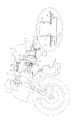
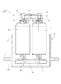
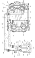
- FIG. 1 shows a fuel supply device for a motorcycle to which the present invention is applied.
- a vertically long fuel tank 2 is disposed in an inner rear half portion of a large-capacity tank cover 1, and a pump is provided through an opening 4 provided in the bottom portion 3.
- An in-tank pump is realized by inserting the unit 5 and attaching the flange-like mounting seat 6 to the bottom 3.
- a discharge pipe 7 is provided in the vicinity of the mounting seat 6, and is sent from the discharge pipe 7 to the intake portion of the forward leaning engine 9 disposed in front of the fuel tank 2 through the fuel pipe 8.
- the fuel pipe 8 is a high-pressure fuel pipe similar to a fuel hose or fuel tube as will be described later.
- An air cleaner 10 is arranged on the front half side of the tank cover 1 in front of the fuel tank 2, an intake pipe 11 is arranged in the vertical direction, and the lower end of the intake pipe 11 is connected to the throttle body 12.
- the throttle body 12 is connected to the intake port 13 of the engine 9.
- the air cleaner 10 and the throttle body 12 constitute an intake portion of the engine 9 and intake air into the intake port 13 in a downdraft manner.
- the throttle body 12 is provided with a throttle valve 14 and a first injector 15 provided on the downstream side thereof, and injects fuel into the intake port 13.
- a second injector 16 is provided at the top of the air cleaner 10 on the axial extension of the intake pipe 11 on the upstream side of the throttle valve 14, and fuel is injected into the intake pipe 11. Fuel is supplied to the first injector 15 and the second injector 16 from branch connectors 17 and 18 branched from the fuel pipe 8, respectively.
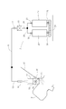
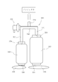
- FIG. 2 schematically shows the fuel supply system.
- the pump unit 5 includes two fuel pumps including a first pump 20 and a second pump 21, and discharges 22 and 23 are connected to each other to perform common discharge.
- a passage 24 is connected to the discharge pipe 7, and a common pressure regulator 25 is connected to the common discharge passage 24.
- the first pump 20 and the second pump 21 suck the fuel through a common fuel filter 26.
- the supply path from the pump unit 5 to each injector is as described above, and fuel is supplied from the branch connector 17 to the first injector 15 via the discharge pipe 7 and the fuel pipe 8, and from the branch connector 18 to the second injector. Fuel is supplied to 16.
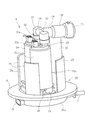
- FIG. 3 is a perspective view of the pump unit 5.
- the pump unit 5 includes a single unit case 28, and a mounting seat 6 having an outer flange shape is integrally formed near the bottom of the pump unit 5.
- the lower bottom portion 28a has a substantially cup shape.
- the two fuel pumps of the first pump 20 and the second pump 21 are each formed in a cylindrical shape and fixed in parallel so that their respective axes are parallel to each other. .
- These first pump 20 and second pump 21 are general-purpose products used for low output. In this embodiment, both fuel pumps have the same performance.
- the fuel pumps are arranged parallel to each other with their central axes directed in the vertical direction, and the discharge ports 22 and 23 at the tops thereof are connected to the common discharge passage 24 via the joint pipe 19.
- the common discharge passage 24 extends substantially horizontally and then communicates with an upper and lower portion 27 arranged in the vertical direction, and a pressure regulator 25 is connected to a bent portion of the upper and lower portion 27.
- the upper and lower portions 27 form part of the common discharge passage 24.
- the pressure regulator 25 is a device that opens when the fuel pressure discharged into the common discharge passage 24 exceeds a predetermined level and returns a part of the fuel into the fuel tank 2. Only one pressure regulator 25 is provided in the common discharge passage 24. It has been.
- the fuel pressure controlled by the pressure regulator 25 is for the large discharge common discharge passage 24 after the discharge amounts of the two discharge ports 22 and 23 are summed, and pressure-adjusts the high-output fuel.
- the lower end portion of the upper and lower portion 27 leads to the discharge pipe 7 that penetrates the bottom portion 28a of the unit case 28 and protrudes to the outside.
- the first pump 20 and the second pump 21 are disposed inside a peripheral wall 29 protruding upward from the bottom portion 28a of the unit case 28, and are supported by these by appropriate means.
- the peripheral wall 29 corresponds to the first pump 20, the second pump 21, and the upper and lower portions 27 that are partly cut out of a standing wall portion that annularly surrounds the periphery of the upper and lower portions 27.
- the gap 29a is provided so that fuel around the pump unit 5 can easily enter the bottom portion 28a of the unit case 28.
- a suction port 31 protrudes from the lower end of the second pump 21 into the bottom portion 28a of the unit case 28, and the lower end is in contact with the upper surface of the fuel filter 26 (the suction port 30 is the same on the first pump 20 side). ing).
- the pump unit 5 is a unit case 28 in which the first pump 20 and the second pump 21, the common discharge passage 24, the pressure regulator 25, and the fuel filter 26 are integrated into a unit.
- the mounting seat 6 can be detachably attached to the bottom of the fuel tank 2 with a bolt (not shown).
- Reference numeral 32 in the drawing is an external connector provided on the outside of the unit case 28, and 32a is a pump-side connector provided on the upper surface of each fuel pump, which is connected to the external connector 32 by a lead wire 33 (FIG. 5).
- the drive of each fuel pump can be controlled by an ECU (not shown). Various data on the vehicle side necessary for driving control of the fuel pump are collected in the ECU.
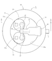
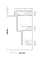
- FIG. 4 is a plan view of the pump unit 5
- FIG. 5 is a sectional view taken along line 5-5 of FIG. 4
- FIG. 6 is a sectional view taken along line 6-6 of FIG.
- the common discharge passage 24 and the joint pipe 19 are T-shaped, and the first pump 20 and the second pump 21 are arranged in parallel on the left and right sides of the axis of the common discharge passage 24.
- the upper and lower parts 27 are divided into an upper pipe 27 a and a lower pipe 27 b at an intermediate part in the vertical direction, and they are integrated by being fitted inside and outside.
- a seal 34 is provided at the fitting portion.
- a common discharge passage 24 that protrudes inward horizontally and a socket portion 35 that protrudes outward and open are provided at the upper end of the upper pipe 27a.
- the socket portion 35 communicates with the common discharge passage 24 and the upper pipe 27a, and the pressure regulator 25 is fitted through a seal 36.
- the lower side of the lower pipe 27 b passes through the bottom portion 28 a of the unit case 28, bends horizontally and extends radially outward, and this portion is the discharge pipe 7.
- the fuel filter 26 common to the first pump 20 and the second pump 21 is accommodated in the bottom portion 28 a of the unit case 28, and the suction port 30 of the first pump 20 and the suction of the second pump 21 are disposed on the upper surface thereof. Mouth 31 is in close contact. Since the fuel filter 26 is commonly used for the first pump 20 and the second pump 21, it has a larger filter capacity than the total required capacity required for each fuel pump. The upper surface of the fuel filter 26 is supported by the suction ports 30 and 31, but is fixed onto the bottom of the unit case 28 using other appropriate fixing means as necessary.
- the joint pipe 19 connected to each discharge port 22, 23 is provided with a cap portion 37 at both ends in the length direction, and can be easily connected by covering this with each discharge port 22, 23. A seal 38 is provided at the fitting portion.
- the pump unit 5 is attached to the fuel tank 2 by inserting the fuel pump side into the fuel tank 2 and fixing the mounting seat 6 to the bottom 3 of the fuel tank 2 with bolts or the like.
- each of the first pump 20 and the second pump 21 simultaneously sucks the fuel in the fuel tank 2 from the bottom portion 28a of the unit case 28 through the fuel filter 26 and discharges the fuel.
- the fuel discharged from the fuel pumps 22 and 23 is fed from the fuel pumps through the common discharge passage 24 and supplied to the first injector 15 and the second injector 16 while being regulated by the pressure regulator 25.
- the fuel supplied from the pump unit 5 must be supplied to the first injector 15 and the second injector 16 at the same time, so that a large amount of fuel is required.
- the two fuel pumps of the first pump 20 and the second pump 21 can supply a sufficient amount of fuel comparable to the supply amount of the conventional high-power fuel pump, such a large amount of fuel can be easily supplied. Can supply.
- the first pump 20 and the second pump 21 themselves constituting the pump unit 5 are of a low output type that cannot output such a high output. Since such a low-power type fuel pump is versatile and relatively inexpensive, the total cost of using two fuel pumps is much higher than that of one high-power type fuel pump having two power outputs. It will be cheaper. Therefore, the pump unit of the present invention has high performance at low cost.
- the mounting seat 6 can be attached to and detached from the bottom 3 of the fuel tank 2 with a bolt or the like. It can be easily attached and detached, and can be easily handled as if it were composed of a single high-power fuel pump.
- the common discharge passage 24 including the upper and lower portions 27
- the pressure regulator 25, the fuel filter 26, and the like are made common, a plurality of fuel pumps are used and the fuel supply device has a high output. Can be made more compact and cost can be further reduced.
- first pump 20 and the second pump 21 constituting the pump unit 5 are each formed in a cylindrical shape and arranged in parallel so that the respective axes are parallel to each other, they are fixed to the common unit case 28.
- the pump unit 5 can be made more compact.
- each fuel pump need only have a lower output, it is versatile and can contribute to further cost reduction.
- the present invention is not limited to the above-described embodiments, and various modifications and applications can be made within the principle of the invention.
- the number of fuel pumps used is not limited as long as the number is two or more. This can be determined by a balance between the required performance and the total cost of the general-purpose fuel pump used and the allowable size when unitized.
- the common part may be either the pressure regulator 25 or the fuel filter 26.
- the fuel may be supplied simultaneously to a plurality of injectors as in the embodiment, or conversely, the fuel may be supplied to only one injector.
- the plurality of fuel pumps may be a combination of the same output or a combination of different outputs.
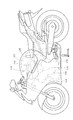
- FIG. 7 is a side view of a motorcycle equipped with a V-type multi-cylinder engine 109
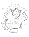
- FIG. 8 is a schematic cross-sectional view showing an intake structure of the V-type multi-cylinder engine 109.
- a fuel tank 102 and an air cleaner 118 are provided above the V-type multi-cylinder engine 109, and the air cleaner 118 is located above the V bank 150 of the V-type multi-cylinder engine 109 and is located below the air cleaner 118.
- a throttle body 112 is disposed in the bank 150.
- a pump unit 105 is accommodated in the fuel tank 102, and fuel is supplied from the pump unit 105 to the front bank 151 and the rear bank 152.
- the V bank 150 has a substantially V-shaped space when viewed from the side sandwiched between a front bank 151 inclined obliquely forward and a rear bank 152 inclined obliquely rearward.
- the intake banks 153 and 154 are provided in the front bank 151 and the rear bank 152, respectively, and are connected to the throttle body 112.
- the number of intake passages 153 and 154 is provided in accordance with the number of cylinders. In this embodiment, two intake passages 153 and 154 are provided in each of the front bank 151 and the rear bank 152.
- the throttle body 112 is mounted from above the V bank 150 and includes a front throttle body 112a connected to the intake passage 153 of the front bank 151 and a rear throttle body 112b connected to the intake passage 154 of the rear bank 152. Each of the front throttle body 112a and the rear throttle body 112b is also a small throttle body.
- the throttle body 112 is an assembly of these small throttle bodies.
- the number of small throttle bodies is arbitrarily determined according to the shape of the engine and the number of cylinders.
- the front throttle body 112a includes intake pipes 161 and injectors 163 for the number of intake passages to be attached.
- two intake pipes are provided, and one intake pipe 161 and one injector 163 are paired and connected to two intake passages 153 provided in the front bank 151.
- the rear throttle body 112b which includes two intake pipes 162 and two injectors 164, each connected to two intake passages 154 provided in the rear bank 152.
- the number of intake pipes and injectors is increased or decreased according to the number of cylinders.
- a first delivery pipe 165 is connected to the injector 163 on the intake passage 153 side, and a second delivery pipe 166 is connected to the injector 164 on the intake passage 154 side.
- the first delivery pipe 165 and the second delivery pipe 166 are arranged parallel to each other with a space therebetween, and each is connected to a fuel hose 168 via a branch connector 167, supplied with high-pressure fuel from the pump unit 105, and intake air from each injector.
- Fuel is injected into the passages 153 and 154. It is known that the atomized particles of fuel injected from the injector are smaller as the discharge pressure is higher, and the startability is excellent.
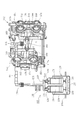
- FIG. 9 is a block diagram of the fuel supply device of the second embodiment used in the V-type multi-cylinder engine 109.
- the throttle body 112 is connected to the pump unit 105 via a fuel hose 168.
- a first connector 170 and a second connector 171 are provided at both ends of the fuel hose 168.
- the fuel hose 168 is connected to the pump unit 105 via the first connector 170, and a set of branch connectors 167 is connected via the second connector 171.
- the branch connector 167 is substantially T-shaped, and is connected to a socket 175 provided in the middle portion in the longitudinal direction of the first delivery pipe 165 by one branch portion 173 branching left and right from the collecting portion 172.
- injectors 163 Connected to both ends of the first delivery pipe 165 are injectors 163 (see FIG. 8, which is not visible under the first delivery pipe 165 in this figure, but shows its attachment position as an attachment line L). Fuel is supplied from the first delivery pipe 165 to the injector 163. The other branch portion 174 of the branch connector 167 is connected to the socket 176 formed at the intermediate portion in the longitudinal direction of the second delivery pipe 166 by fitting. Also connected to the second delivery pipe 166 is an injector 164 (see FIG. 8, which is not visible under the second delivery pipe 166 in this figure, but its attachment position is shown as an attachment line L).
- the first delivery pipe 165 and the second delivery pipe 166 are fixed on the cases of the front throttle body 112a and the rear throttle body 112b by bolts 169 at both ends in the length direction.
- Each injector is controlled by an ECU (not shown), and by supplying fuel for an appropriate time, an appropriate amount of fuel is accurately supplied into each intake passage.
- the pump unit 105 is the same as that of the previous embodiment, in which the first pump 120 and the second pump 121 having the same performance are integrated into a common unit case 128.
- the first pump 120 and the second pump 121 is driven simultaneously, and a simple calculation is performed to obtain twice the discharge amount.
- the fuel filter 126 provided in the unit case 128 and the pressure regulator 125 provided in the common discharge passage 124 are shared, and these constituent members are the same as those in the previous embodiment, and thus detailed description thereof is omitted.
- Reference numerals 122 and 123 in the figure denote discharge ports, which are connected to the joint pipe 119 via check valves 129 for preventing backflow provided in the respective outlets, and the first pump 120 and the second pump 121 are connected in parallel. Has been placed.
- Reference numerals 130 and 131 denote suction ports. In this way, a discharge amount approximately twice that when the fuel pump is used alone is obtained, and a sufficient amount of fuel can be appropriately and evenly supplied to the cylinders of the front bank 151 and the rear bank 152.
- the common discharge passage 124 is connected to one end of the fuel hose 168 through the first connector 170, and the other end of the fuel hose 168 is connected to the T-shaped branch connector 167 through the second connector 171.
- the branch connector 167 is located at the center between the first delivery pipe 165 and the second delivery pipe 166 on the left and right sides. This allows a simple piping structure, and the expensive connector requiring attention to connection includes the first connector 170 and Only two of the second connectors 171 can be used.
- FIG. 10 shows a third embodiment having a fuel supply structure for a V-type engine different from FIG.
- the pump unit 205 two pumps composed of the first pump 220 and the second pump 221 having the same performance are combined and integrated in the unit case 228.
- the first pump 220 is appropriately ON / OFF controlled according to the operating state of the engine, and the second pump 221 is always driven.
- a first discharge passage 224 and a second discharge passage 244, which are separate discharge passages, are provided for the first pump 220 and the second pump 221, respectively, between the first discharge passage 224 and the second discharge passage 244.
- the first discharge passage 224 and the second discharge passage 244 further extend independently from this joining portion, and are connected to the first fuel hose 268 and the second fuel hose 278, respectively.
- the first discharge passage 224 is connected to one end of the first fuel hose 268 by the first connector 270, and the other end of the first fuel hose 268 is connected to one end of the second delivery pipe 166 by the second connector 271.
- the second discharge passage 244 is connected to one end of the second fuel hose 278 by a third connector 280, and the other end of the second fuel hose 278 is connected to one end of the first delivery pipe 165 by a fourth connector 281.
- the pressure regulator 225 is provided only on the downstream side of the joining portion of the first discharge passage 224, and is not provided on the second discharge passage 244 side. The pressure regulator 225 is used in common to reduce the number of use.
- the throttle body is the same as the throttle body 112 of the previous embodiment except for the fuel piping structure, common parts are denoted by common reference numerals.
- the first delivery pipe 165 and the second delivery pipe 166 are connected to the independent second fuel hose 278 and the first fuel hose 268, respectively, and are connected by a branch connector as in the previous embodiment. Without being independent of each other.
- Two injectors are connected to the first delivery pipe 165 (in this figure, it is not visible under the first delivery pipe 165, but its attachment position is shown as an attachment line L), from the first delivery pipe 165 Fuel is supplied to each connected injector.
- an injector is also connected to the second delivery pipe 166 (in this figure, it cannot be seen under the second delivery pipe 166, but its attachment position is shown as an attachment line L), and from the second delivery pipe 166, Supply fuel to the connected injectors.
- the engine in this embodiment is a variable cylinder formula, and the cylinders in the rear bank 152 (see FIG. 8) are configured as idle cylinders, and the cylinders are deactivated by stopping the operation of the injector 164 (see FIG. 8). It has become.
- the injector is controlled by an ECU (not shown) on the basis of various sensor information relating to the operating state and traveling state of the engine, such as vehicle speed, acceleration, engine speed, and engine temperature.
- the engine 109 is in a general traveling state where high output and discharge pressure are not required, and the injector is operated during a driving situation where high output and discharge pressure are required, such as during start-up and acceleration, and the cylinder is deactivated. Is activated. Fuel consumption can be improved by adopting such a cylinder deactivation system.
- the pump unit 205 is different only in the above-described configuration, and the other configurations are the same as those in the previous embodiment.
- the pump unit 205 includes a common unit case 228 and a fuel filter 226 and is unitized.
- Reference numerals 222 and 223 in the figure denote discharge ports, which are connected to the first discharge passage 224 and the second discharge passage 244 via check valves 229 and 239 for preventing backflow, respectively, and are connected to the discharge port by a communication pipe 245. Since 222 and 223 communicate with each other, the first pump 220 and the second pump 221 are arranged in parallel connection.
- Reference numerals 230 and 231 denote suction ports.
- the first pump 220 operates only at a specific time such as a start when a high discharge pressure is required or a high output of an engine that requires a large amount of fuel, and is stopped during normal driving when the cylinder on the rear bank is deactivated. .
- the second pump 221 is always driven and supplies fuel to both the first fuel hose 268 and the second fuel hose 278 or only to the second fuel hose 278.
- the control of the first pump 220 is performed by an ECU (not shown) based on various sensor information related to the engine operating state and the traveling state such as the vehicle speed, acceleration, engine speed, and engine temperature.
- the second pump 221 branches and supplies the fuel to the first fuel hose 268 and the second fuel hose 278 via the communication pipe 245.
- the injector 164 (FIG. 8) of the second delivery pipe 166 is stopped, so the fuel supply to the first fuel hose 268 is stopped, and the second fuel hose 278 Fuel is supplied only to the injector 163 (FIG. 8) of the one delivery pipe 165, and only the cylinder on the front bank 151 (FIG. 8) side is operated.
- the second pump 221 branches and supplies the fuel to the first fuel hose 268 and the second fuel hose 278 via the communication pipe 245, and the first delivery pipe 165 and the first delivery pipe 165 2. Fuel is injected from each injector of the delivery pipe 166, and all cylinders are activated. This state is the lowest output state in which the fuel distributed to each cylinder is minimized, and the second pump 221 is set to a performance capable of supplying fuel to all the cylinders.
- the fuel of the first pump 220 is mainly supplied from the first fuel hose 268 to the second delivery pipe 166, and the fuel of the second pump 221 is mainly supplied from the second fuel hose 278 to the first delivery pipe. 165.
- the communication pipe 245 communicates, the discharge pressure of the fuel supplied to the first fuel hose 268 and the second fuel hose 278 is averaged, and the first delivery pipe 165 and the second delivery pipe Fuel is uniformly injected from each of the injectors 166.
- the fuel discharge amount and the discharge pressure can be increased as compared with the case where the fuel is supplied to all cylinders by the second pump 221 alone. Can increase the output. Further, when the discharge pressure is increased, the supplied fuel is further reduced in diameter, so that the startability can be improved.
- first pump 220 in this embodiment Since one fuel pump (first pump 220 in this embodiment) is intermittently operated in this way, the engine is suitable for the idle cylinder type, and when the first pump 220 is stopped, the cylinder on the rear bank 152 side can be deactivated. . At this time, only the front bank 151 side can continue to operate with the second pump 221, and the fuel efficiency can be improved comprehensively. In addition to simultaneously moving two pumps, it can be controlled to move individually, so that the second pump (first pump 220 in this embodiment) is driven only when a large amount of fuel is required. In other cases, by driving only one pump (second pump 221 in this embodiment), it is possible to save power, reduce sound, and reduce exhaust heat.
- the pump unit 205 as a whole is a variable displacement type in which the amount of fuel to be supplied is variable, and an expensive variable capacity fuel pump can be realized with a simple structure at low cost.
- the branch connector 167 of the previous embodiment can be omitted, and the first and second delivery pipes 165 and 166 are also provided in the middle portion in the longitudinal direction. It can be simplified as much as sockets can be omitted.
- FIG. 11 schematically shows a configuration of a pump unit 305 according to the fourth embodiment in which a plurality of fuel pumps having different discharge flow rates and power consumptions are combined to form a unit.
- the pump unit 305 two pumps composed of the first pump 320 and the second pump 321 having different performances are combined and integrated.
- the first pump 320 has a small fuel discharge flow rate and power consumption suitable for low-load operation of the engine.
- the second pump 321 is relatively larger in fuel discharge flow rate and power consumption than the first pump 320, and is suitable for medium load operation of the engine.
- the first discharge passage 322 extending from the discharge port 329 of the first pump 320 and the second discharge passage 344 extending from the discharge port 339 of the second pump 321 are connected to the common discharge passage 324 via the communication pipe 345.
- a pressure regulator 325 is provided at a connection portion between the first discharge passage 322 and the communication pipe 345 so that excess fuel is returned to the fuel tank as a regulator return.
- the common discharge passage 324 is connected to a fuel pipe or a fuel hose, and supplies fuel to the injectors in the throttle body of the first and second embodiments.
- separate fuel filters 326 and 346 are attached to the suction port 330 of the first pump 320 and the suction port 331 of the second pump 321. These fuel filters 326 and 346 have different capacities depending on the discharge flow rate of each fuel pump. In this example, the fuel filter 326 in the first pump 320 has a small capacity, and the fuel filter 346 in the second pump 321. The capacity of is relatively large.
- the first pump 320 and the second pump 321 together with the fuel filters 326 and 346 having different capacities are integrated into a common unit case (not shown) and integrated into a single unit as in the previous embodiments. It functions as a variable displacement fuel pump unit.
- the pump unit 305 is formed by forming the first and second fuel pumps in a cylindrical shape and arranging them in parallel so that their respective axes are parallel to each other. Since the fuel pump can be fixed to a common mounting seat (see FIG. 3) in a state where the fuel pumps are close to each other, the pump unit 305 can be made more compact. Further, by attaching the mounting seat 6 to the bottom of the fuel tank 2 (see FIG. 1), it is possible to easily attach and detach the fuel tank.
- the first pump 320 and the second pump 321 are controlled by an ECU or the like (not shown) according to the operating state of the engine, and in the low load state, the first pump 320 is operated alone and the second pump 321 is stopped.
- the operation state is set to a second operation state in which the first pump 320 is deactivated and the second pump 321 is operated independently when in an intermediate load state, and the first pump 320 and the second pump 321 are simultaneously operated in a high load state.
- the operation state can be switched so that the operation state 3 is obtained.
- FIG. 12 is a graph showing the relationship between the fuel discharge flow rate and power consumption in the pump unit 305 with respect to changes in the engine load state.
- the load state in the practical operating range of the engine is divided into a low load state with the lowest load, a high load state with the highest load such as a full throttle state, and an intermediate load state that is intermediate between them.
- the required fuel discharge flow rate is a
- the fuel discharge flow rate required in the medium load state is b
- the fuel discharge flow rate required in the high load state is c
- the fuel discharge flow rate a determined in this way is set as the fuel discharge flow rate of the first pump 320
- the fuel discharge flow rate b is set as the fuel discharge flow rate of the second pump 321.
- the fuel discharge flow rate of the pump unit 305 becomes a suitable for the low load state. If one pump 320 is stopped and the second pump 321 is operated alone, the fuel discharge flow rate of the pump unit 305 becomes b adapted to the medium load state, and the first pump 320 and the second pump 321 are turned on in the high load state. If operated simultaneously, the fuel discharge flow rate of the pump unit 305 becomes c adapted to the high load state.
- the power consumption of the first pump 320 having a small fuel discharge flow rate is small
- the power consumption of the second pump 321 having a larger fuel discharge flow rate is larger
- each of the first pump 320 and the second pump 321 is in a high load state. This is the largest sum of power consumption. Accordingly, as shown in FIG. 12, the fuel discharge flow rate increases stepwise in the order of the low load state, medium load state, and high load state, and the power consumption also increases stepwise.
- the pump unit 305 when the pump unit 305 is configured by the combination of the first pump 320 and the second pump 321 having different performance differences between the fuel discharge flow rate and the power consumption, it is simple to combine the operation or stop of each pump. Since the control enables stepwise fuel supply in accordance with the operating state of the engine, the fuel discharge flow rate of the pump unit 305 can be changed step by step without complicated control. Sometimes it becomes possible to secure the necessary fuel discharge flow rate.
- the pump unit 305 does not supply fuel to the injector of the throttle body from the merged common discharge passage 324 as in the first or second embodiment, and is applied to the throttle body of the engine having the idle cylinder as in the third embodiment. On the other hand, it can also supply from several discharge passages.
Abstract
Description
また、スロットル全開時のような高負荷時に必要な燃料吐出流量を確保するために大流量ポンプを採用した場合には、低負荷領域等では吐出燃料の多くがプレッシャーレギュレータから戻される燃料タンク側へ戻されるレギュレータリターン分となり、この分だけ無駄な電力を消費することになるため、必要なときに必要な流量を確保して電気負荷を低減することも望まれる。
一方、上記複数の燃料ポンプを用いるものは、単に各分割タンクの死残量を少なくするため、各分割タンク毎に設けるものであるから、ポンプ出力を高めるものではなく、かつ使用数に比例したコストがかかることになる。
また、複数個の燃料ポンプを組み合わせて大吐出量の大型燃料ポンプとして機能させるものは、既存の燃料ポンプを複数併用することにより、新規に単独の大型燃料ポンプを設計する必要がないので、高性能な燃料ポンプを簡単かつ安価に得ることができる。しかし目的とする吐出量に応じて既存の燃料ポンプを単に組み合わせ、一つの燃料ポンプとして機能するように共通にコントロールするものであるから、個々の燃料ポンプの構成は従来と同様に燃料フィルタやハウジング等をそれぞれが独立して備えることになり、組み合わされた新規燃料ポンプ全体における構成部品の点数やコストは、単純に構成する燃料ポンプ数に比例するものであり、かつ装置全体の大きさは単なる集合体である以上、個々の大きさを単に合算したものよりも大きくならざるを得ないので、より部品点数やコストを削減できかつコンパクト化できることが望まれる。
そこで本願発明は、上記要請の実現を目的とする。
When using a pump with a different pump output according to the engine output, a high output fuel pump must be provided for a high output engine, resulting in high costs. It would be desirable to be able to use some low power fuel pump.
In addition, when a large flow pump is used to secure the required fuel discharge flow rate when the load is high, such as when the throttle is fully open, in the low load range, etc., much of the discharged fuel is returned to the fuel tank side where it is returned from the pressure regulator. The amount of the regulator return is returned, and wasteful power is consumed by this amount. Therefore, it is also desired to secure the necessary flow rate and reduce the electrical load when necessary.
On the other hand, those using a plurality of fuel pumps are provided for each of the divided tanks in order to simply reduce the amount of dead fuel in each of the divided tanks, and therefore do not increase the pump output and are proportional to the number of uses. It will be costly.
In addition, a combination of multiple fuel pumps that can function as a large-capacity fuel pump with a large discharge amount can be used in combination with multiple existing fuel pumps, so there is no need to design a single large-scale fuel pump. A high-performance fuel pump can be obtained easily and inexpensively. However, the existing fuel pumps are simply combined according to the target discharge amount, and are controlled in common so that they function as one fuel pump. Etc., and the number and cost of the components in the combined new fuel pump are proportional to the number of fuel pumps that are simply configured, and the overall size of the apparatus is simply Since it is an aggregate, it must be larger than the sum of the individual sizes, so it is desirable to be able to reduce the number of parts and cost and make it more compact.
Therefore, the present invention aims to realize the above request.
前記燃料ポンプが、複数個備えられ、各吸入口を共通の燃料フィルタへ接続したことを特徴とする。 In order to solve the above-described problems, a first aspect of the present invention provides a fuel supply apparatus that supplies fuel to an engine by a fuel pump disposed in a fuel tank.
A plurality of the fuel pumps are provided, and each suction port is connected to a common fuel filter.
前記燃料ポンプは、複数個備えられ、
これら複数の燃料ポンプは、燃料吐出流量と消費電力を相対的に大小異にする第1の燃料ポンプと第2の燃料ポンプを含み、
前記エンジンの運転状況に応じて、
前記第1の燃料ポンプを作動させかつ前記第2の燃料ポンプを休止させて前記エンジンに燃料を供給する第1の運転状態と、
前記第2の燃料ポンプを作動させかつ前記第1の燃料ポンプを休止させて前記エンジンに燃料を供給する第2の運転状態と、
前記第1及び第2の燃料ポンプを両方作動させて前記エンジンに燃料を供給する第3の運転状態と、
のいずれかに切り換えて前記エンジンに燃料を供給することを特徴とする。 The invention of
A plurality of the fuel pumps are provided,
The plurality of fuel pumps include a first fuel pump and a second fuel pump that make the fuel discharge flow rate and power consumption relatively large and small,
Depending on the operating status of the engine,
A first operating state of operating the first fuel pump and deactivating the second fuel pump to supply fuel to the engine;
A second operating state of operating the second fuel pump and stopping the first fuel pump to supply fuel to the engine;
A third operating state in which both the first and second fuel pumps are operated to supply fuel to the engine;
The fuel is supplied to the engine by switching to any of the above.
The invention of
これら第1及び第2の燃料ポンプを両方作動させる第3の運転状態とのいずれかに切り換えることができる。このため、各ポンプの作動又は停止を組合せるだけの単純な制御で、エンジンの運転状態に応じた段階的な燃料供給が可能になり、複雑な制御をすることなく段階的に全体の燃料吐出流量を変化させることができるようになる。
しかも、消費電力が大小に異なるポンプを組み合わせることにより、運転状況に応じて消費電力を最適状態に変化させることができるので、必要なときに必要な燃料吐出流量を確保して電気負荷を低減することができる。このため、消費電力を抑制し、発電機を小型化することも可能になり、さらに燃費も向上できる。 According to the seventh aspect of the present invention, since the fuel pump includes the plurality of fuel pumps including the first fuel pump and the second fuel pump that make the fuel discharge flow rate and the power consumption relatively different from each other, In response, a first operating state in which the first fuel pump is activated and the second fuel pump is deactivated, and a second operational state in which the second fuel pump is activated and the first fuel pump is deactivated. ,
It is possible to switch to either the third operating state in which both the first and second fuel pumps are operated. This makes it possible to supply fuel stepwise according to the operating state of the engine with simple control that combines the operation or stop of each pump, and the entire fuel discharge step by step without complicated control. The flow rate can be changed.
Moreover, by combining pumps with different power consumption, the power consumption can be changed to the optimum state according to the operating conditions, so that the necessary fuel discharge flow rate is secured when necessary to reduce the electrical load. be able to. For this reason, it becomes possible to suppress power consumption, to reduce the size of the generator, and to improve fuel efficiency.
また、各燃料ポンプを近接させた状態で共通の取付座へ固定することができるため、ポンプユニットをよりコンパクトにすることができる。
According to the invention of
Moreover, since each fuel pump can be fixed to a common mounting seat in a state where the fuel pumps are close to each other, the pump unit can be made more compact.
2: fuel tank, 3: bottom, 5: pump unit, 6: mounting seat, 20: first pump, 21: second pump, 24: common discharge passage, 25: pressure regulator, 26: fuel filter, 105: pump Unit: 109: V-type multi-cylinder engine, 120: first pump, 121: second pump, 124: common discharge passage, 125: pressure regulator, 126: fuel filter, 165: delivery pipe, 166: delivery pipe, 167: Branch connector, 168: fuel hose, 170: first connector, 171: second connector, 205: pump unit, 220: first pump, 221: second pump, 224: first discharge passage, 225: pressure regulator, 226 : Fuel filter, 244: second discharge passage, 278: second fuel hose, 28 : Third connector, 281: fourth connector, 305: pump unit, 320: first pump, 321: second pump, 322: first discharge passage, 324: common discharge passage, 325: pressure regulator, 326: fuel filter 344: Second discharge passage 346: Fuel filter
プレッシャーレギュレータ25は共通吐出通路24内へ吐出された燃圧が所定以上になったとき開いて、燃料の一部を燃料タンク2中へ戻すための装置であり、共通吐出通路24に一つだけ設けられている。プレッシャーレギュレータ25がコントロールする燃圧は、2個の吐出口22,23の吐出量が合計された後の大流量の共通吐出通路24に対するものであり、高出力の燃料を圧力調整している。 The
The
図5において、上下部27は上部パイプ27aと下部パイプ27bに上下方向中間部で分割され、それぞれを内外に嵌合して一体化している。嵌合部にはシール34が設けられている。上部パイプ27aの上端には水平に内方へ突出する共通吐出通路24と、外方へ突出して開放されたソケット部35が設けられている。ソケット部35は共通吐出通路24及び上部パイプ27aと連通し、かつプレッシャーレギュレータ25がシール36を介して嵌合されている。
下部パイプ27bの下部側は、ユニットケース28の底部28aを貫通し、水平に屈曲して径方向外方へ延出し、この部分が吐出パイプ7となっている。 4 is a plan view of the
In FIG. 5, the upper and
The lower side of the
各吐出口22,23へ接続するジョイント管19は長さ方向両端にキャップ部37を備え、これを各吐出口22,23へ被せることにより容易に接続される。嵌合部にはシール38が設けられている。 In FIG. 6, the
The
また、ポンプユニット5を構成する第1ポンプ20及び第2ポンプ21をそれぞれ筒状に形成してそれぞれの軸線が互いに平行になるように並列に配置して共通のユニットケース28へ固定したので、ポンプユニット5をよりコンパクトにすることができる。
しかも、個々の燃料ポンプはより低出力のもので足りるので、汎用性があり、かつさらなるコストダウンに貢献できる。 Moreover, since the
In addition, since the
In addition, since each fuel pump need only have a lower output, it is versatile and can contribute to further cost reduction.
また、部品の共通化はプレッシャーレギュレータ25又は燃料フィルタ26のいずれか一方であっても良い。
さらに、実施例のように複数のインジェクタへ同時に燃料を供給しても、逆に一つだけのインジェクタへ燃料を供給してもよい。
複数の燃料ポンプは、同じ出力のものの組み合わせでもよいし、出力の違うものの組み合わせでもよい。 Note that the present invention is not limited to the above-described embodiments, and various modifications and applications can be made within the principle of the invention. For example, the number of fuel pumps used is not limited as long as the number is two or more. This can be determined by a balance between the required performance and the total cost of the general-purpose fuel pump used and the allowable size when unitized.
Further, the common part may be either the
Further, the fuel may be supplied simultaneously to a plurality of injectors as in the embodiment, or conversely, the fuel may be supplied to only one injector.
The plurality of fuel pumps may be a combination of the same output or a combination of different outputs.
燃料タンク102内にはポンプユニット105が収容され、このポンプユニット105から前バンク151及び後バンク152へ燃料が供給される。 Next, another embodiment applied to a V-type multi-cylinder engine will be described. 7 is a side view of a motorcycle equipped with a V-
A
なお、インジェクタより噴射される燃料の霧化粒子は吐出圧が高いほど小さくなり、始動性に優れたものになることが知られている。 A
It is known that the atomized particles of fuel injected from the injector are smaller as the discharge pressure is higher, and the startability is excellent.
第2デリバリーパイプ166にもインジェクタ164(図8参照、なおこの図においては第2デリバリーパイプ166の下になって見えないが、取付線Lとしてその取付位置を示す)が接続している。第1デリバリーパイプ165及び第2デリバリーパイプ166はそれぞれ長さ方向両端でボルト169により前部スロットルボディ112a及び後部スロットルボディ112bのケース上へ固定されている。各インジェクタは図示省略のECUにより制御され、適正な時間だけ燃料噴射することにより適正な量の燃料を各吸気通路内へ正確に供給する。 Connected to both ends of the
Also connected to the
第1デリバリーパイプ165には2個のインジェクタが接続し(この図においては第1デリバリーパイプ165の下になって見えないが、取付線Lとしてその取付位置を示す)、第1デリバリーパイプ165から接続する各インジェクタへ燃料を供給する。
同様に、第2デリバリーパイプ166にもインジェクタが接続し(この図においては第2デリバリーパイプ166の下になって見えないが、取付線Lとしてその取付位置を示す)、第2デリバリーパイプ166から接続するインジェクタへ燃料を供給する。 Since the throttle body is the same as the
Two injectors are connected to the first delivery pipe 165 (in this figure, it is not visible under the
Similarly, an injector is also connected to the second delivery pipe 166 (in this figure, it cannot be seen under the
第1ポンプ220の制御は、図示しないECUにより、車速・加速度・エンジン回転数・エンジン温度等、エンジンの運転状況及び走行状況に関する各種のセンサ情報に基づいて行われる。 The
The control of the
このように第1ポンプ220及び第2ポンプ221を同時に駆動すると、第2ポンプ221単独で全気筒へ燃料を供給するときと比べて、燃料の吐出量及び吐出圧を増大させることができ、エンジンの出力を高めることができる。また吐出圧を高くすると、供給される燃料がより細径化するので、始動性を良好にすることができる。 When the
When the
また、2個あるポンプを同時に動かす以外にも、個別に動かすように制御できるので、大量の燃料を必要とするときにだけ2個目のポンプ(本実施例では第1ポンプ220)を駆動させ、他の場合は1個のポンプ(本実施例では第2ポンプ221)のみ駆動させることにより、省電力化、低音化、低排出熱化が可能になる。
しかも、ポンプユニット205全体としては、供給する燃料の量を可変とする容量可変型となり、高価な容量可変型の燃料ポンプを簡単な構造で安価に実現できる。
また、第2燃料ホース278,第3コネクタ280,第4コネクタ281が増加する反面、前実施例の分岐コネクタ167を省略でき、第1及び第2デリバリーパイプ165,166も長さ方向中間部のソケットを省略できる分だけ単純化できる。 Since one fuel pump (
In addition to simultaneously moving two pumps, it can be controlled to move individually, so that the second pump (
In addition, the
Further, while the
この実施例では、ポンプユニット305において、異なる性能の第1ポンプ320と第2ポンプ321からなる2個のポンプを組み合わせて一体化したものである。
第1ポンプ320は燃料吐出流量及び消費電力がエンジンの低負荷運転に適合した小さなものである。第2ポンプ321は燃料吐出流量及び消費電力が第1ポンプ320よりも相対的に大きく、エンジンの中負荷運転に適合したものである。 FIG. 11 schematically shows a configuration of a
In this embodiment, in the
The
したがって、図12に示すように、低負荷状態、中負荷状態、高負荷状態の順に燃料吐出流量が段階的に増大し、消費電力も同様に段階的に増大することになる。 Further, the power consumption of the
Accordingly, as shown in FIG. 12, the fuel discharge flow rate increases stepwise in the order of the low load state, medium load state, and high load state, and the power consumption also increases stepwise.
しかも、消費電力が大小に異なるポンプを組み合わせることにより、運転状況に応じて消費電力を最適状態に変化させることができるので、消費電力を抑制し、発電機(ACG)を小型化することも可能になる。このため、電気負荷の低減により燃費を向上できる。 As a result, it is not necessary to use a large flow pump to secure the required fuel discharge flow rate c at high loads such as when the throttle is fully open, and a large amount of regulator return is not generated in a low load region. Wasted power consumption can be suppressed by this reduced regulator return.
Moreover, by combining pumps with different power consumption, the power consumption can be changed to the optimum state according to the operating conditions, so it is possible to reduce power consumption and reduce the size of the generator (ACG). become. For this reason, fuel consumption can be improved by reducing the electrical load.
さらに、ポンプユニット305は第1又は第2実施例のような合流した共通吐出通路324からスロットルボディのインジェクタへ燃料を供給せず、第3実施例のように休止気筒を有するエンジンのスロットルボディに対して複数の吐出通路から供給することもできる。 In the above description, the combination of two pumps with different fuel discharge flow rates and power consumptions has been described. However, it is sufficient that there are a plurality of pumps to be combined. For example, a medium-load pump can be used for fuel discharge flow rate and power consumption. If combined with those having two or more performance differences, the fuel discharge flow rate in the middle load region can be controlled more precisely. It is also possible to combine low or medium load pumps with the same performance.
Further, the
Claims (8)
- 燃料タンク内に配置された燃料ポンプにより燃料をエンジンに供給する燃料供給装置において、
前記燃料ポンプは、複数個備えられ、各吸入口を共通の燃料フィルタへ接続したことを特徴とする燃料供給装置。 In a fuel supply device that supplies fuel to an engine by a fuel pump disposed in a fuel tank,
A fuel supply device comprising a plurality of the fuel pumps, wherein each suction port is connected to a common fuel filter. - 前記燃料ポンプは、複数個備えられ、各吐出口を互いに共通吐出通路へ接続するとともに、この共通吐出通路に一つのプレッシャーレギュレータを配置したことを特徴とする請求項1に記載した燃料供給装置。 2. The fuel supply apparatus according to claim 1, wherein a plurality of the fuel pumps are provided, each discharge port is connected to a common discharge passage, and one pressure regulator is disposed in the common discharge passage.
- 前記複数の燃料ポンプが、燃料タンクの底部へ取付けられる共通の取付座へ一体化されて単一のポンプユニットをなすことを特徴とする請求項1又は2に記載した燃料供給装置。 3. The fuel supply apparatus according to claim 1, wherein the plurality of fuel pumps are integrated into a common mounting seat attached to a bottom portion of the fuel tank to form a single pump unit.
- 前記ポンプユニットは各燃料ポンプ共通の前記燃料フィルタ及びプレッシャーレギュレータを各一つずつ備えることを特徴とする請求項3に記載した燃料供給装置。 4. The fuel supply apparatus according to claim 3, wherein the pump unit includes one fuel filter and a pressure regulator common to each fuel pump.
- 前記ポンプユニットから複数のインジェクタへ燃料を供給することを特徴とする請求項1~4のいずれかに記載した燃料供給装置。 The fuel supply device according to any one of claims 1 to 4, wherein fuel is supplied from the pump unit to a plurality of injectors.
- ポンプユニットを構成する各燃料ポンプは、それぞれ筒状に形成されかつそれぞれの軸線が互いに平行になるように並列に配置されて前記取付座へ固定されることを特徴とする請求項3に記載した燃料供給装置。 4. The fuel pumps constituting the pump unit are formed in a cylindrical shape and are arranged in parallel so that their respective axes are parallel to each other and fixed to the mounting seat. Fuel supply device.
- 燃料タンク内に配置された燃料ポンプにより燃料をエンジンに供給する燃料供給装置において、
前記燃料ポンプは、複数個備えられ、
これら複数の燃料ポンプは、燃料吐出流量と消費電力を相対的に大小異にする第1の燃料ポンプと第2の燃料ポンプを含み、
前記エンジンの運転状況に応じて、
前記第1の燃料ポンプを作動させかつ前記第2の燃料ポンプを休止させて前記エンジンに燃料を供給する第1の運転状態と、
前記第2の燃料ポンプを作動させかつ前記第1の燃料ポンプを休止させて前記エンジンに燃料を供給する第2の運転状態と、
前記第1及び第2の燃料ポンプを両方作動させて前記エンジンに燃料を供給する第3の運転状態と、
のいずれかに切り換えて前記エンジンに燃料を供給することを特徴とする燃料供給装置。 In a fuel supply device that supplies fuel to an engine by a fuel pump disposed in a fuel tank,
A plurality of the fuel pumps are provided,
The plurality of fuel pumps include a first fuel pump and a second fuel pump that make the fuel discharge flow rate and power consumption relatively large and small,
Depending on the operating status of the engine,
A first operating state of operating the first fuel pump and deactivating the second fuel pump to supply fuel to the engine;
A second operating state of operating the second fuel pump and stopping the first fuel pump to supply fuel to the engine;
A third operating state in which both the first and second fuel pumps are operated to supply fuel to the engine;
A fuel supply device that switches to any of the above and supplies fuel to the engine. - 前記ポンプユニットを構成する第1及び第2の燃料ポンプは、それぞれ筒状に形成されかつそれぞれの軸線が互いに平行になるように並列に配置されて共通の取付座に固定することにより一体化されて単一のポンプユニットをなすとともに、さらにこの取付座を燃料タンクの底部へ着脱自在に取付けることを特徴とする請求項7に記載した燃料供給装置。 The first and second fuel pumps constituting the pump unit are each formed in a cylindrical shape and are arranged in parallel so that the respective axes are parallel to each other, and are integrated by being fixed to a common mounting seat. 8. The fuel supply device according to claim 7, wherein the fuel supply device is configured as a single pump unit and is further detachably attached to the bottom of the fuel tank.
Priority Applications (3)
| Application Number | Priority Date | Filing Date | Title |
|---|---|---|---|
| EP09727650.5A EP2261496B1 (en) | 2008-03-31 | 2009-02-18 | Fuel feeding device |
| US12/922,375 US20110011373A1 (en) | 2008-03-31 | 2009-02-18 | Fuel supply device |
| BRPI0910060A BRPI0910060A2 (en) | 2008-03-31 | 2009-02-18 | fuel supply device |
Applications Claiming Priority (4)
| Application Number | Priority Date | Filing Date | Title |
|---|---|---|---|
| JP2008-094400 | 2008-03-31 | ||
| JP2008094400 | 2008-03-31 | ||
| JP2008-238728 | 2008-09-17 | ||
| JP2008238728A JP5133177B2 (en) | 2008-03-31 | 2008-09-17 | Fuel supply device |
Publications (1)
| Publication Number | Publication Date |
|---|---|
| WO2009122798A1 true WO2009122798A1 (en) | 2009-10-08 |
Family
ID=41135197
Family Applications (1)
| Application Number | Title | Priority Date | Filing Date |
|---|---|---|---|
| PCT/JP2009/052781 WO2009122798A1 (en) | 2008-03-31 | 2009-02-18 | Fuel feeding device |
Country Status (5)
| Country | Link |
|---|---|
| US (1) | US20110011373A1 (en) |
| EP (2) | EP2400143B1 (en) |
| JP (1) | JP5133177B2 (en) |
| BR (1) | BRPI0910060A2 (en) |
| WO (1) | WO2009122798A1 (en) |
Cited By (1)
| Publication number | Priority date | Publication date | Assignee | Title |
|---|---|---|---|---|
| US20120152206A1 (en) * | 2010-12-17 | 2012-06-21 | Denso Corporation | Fuel injection device |
Families Citing this family (16)
| Publication number | Priority date | Publication date | Assignee | Title |
|---|---|---|---|---|
| KR101543675B1 (en) | 2008-03-14 | 2015-08-11 | 도레이 카부시키가이샤 | Laminated film |
| JP5139346B2 (en) * | 2008-03-28 | 2013-02-06 | 株式会社デンソー | Fuel supply device |
| JP4893817B2 (en) * | 2009-12-23 | 2012-03-07 | 株式会社デンソー | Fuel supply device |
| JP5682221B2 (en) * | 2010-10-15 | 2015-03-11 | 日産自動車株式会社 | Engine fuel pump control device |
| US20120294732A1 (en) * | 2011-05-17 | 2012-11-22 | Holley Performance Products | Pump System and Method of Use |
| US9879662B2 (en) * | 2011-05-17 | 2018-01-30 | Holley Performance Products, Inc. | Inline pump assembly and method |
| JP6107381B2 (en) * | 2013-04-25 | 2017-04-05 | スズキ株式会社 | Fuel injection device for motorcycle engine |
| GB201320035D0 (en) * | 2013-11-13 | 2013-12-25 | Eaton Aerospace Ltd | Improvements in and relating to fuel pump arrangements |
| WO2015108657A1 (en) * | 2014-01-14 | 2015-07-23 | Holley Performance Products, Inc. | Inline pump assembly and method |
| JP6616728B2 (en) * | 2016-04-06 | 2019-12-04 | 川崎重工業株式会社 | vehicle |
| US10197023B2 (en) * | 2016-11-17 | 2019-02-05 | Ford Global Technologies, Llc | Saddle fuel tank |
| EP3399174B1 (en) * | 2017-05-04 | 2020-11-04 | Volvo Car Corporation | Fuel system for a vehicle, a vehicle comprising such a fuel system and a method for supplying fuel to a combustion engine |
| CN107246632B (en) * | 2017-07-27 | 2023-10-13 | 重庆宙盾新能源技术开发有限公司 | Alcohol-based fuel stove |
| KR102311668B1 (en) * | 2017-09-21 | 2021-10-13 | 현대자동차주식회사 | Selective fuel regulator for two types of fuel tanks |
| JP6806720B2 (en) * | 2018-02-05 | 2021-01-06 | 本田技研工業株式会社 | Intake device for saddle-riding vehicle |
| CN113446139B (en) * | 2021-07-26 | 2022-11-15 | 温州嘉豪石油机械有限公司 | Automobile fuel pump |
Citations (4)
| Publication number | Priority date | Publication date | Assignee | Title |
|---|---|---|---|---|
| JPS61111884U (en) | 1984-12-27 | 1986-07-15 | ||
| WO2006036854A2 (en) * | 2004-09-24 | 2006-04-06 | Millennium Industries Corp. | Multiple pump fuel delivery system |
| JP2006315681A (en) | 2006-08-21 | 2006-11-24 | Honda Motor Co Ltd | Fuel tank for motorcycle |
| JP2007321583A (en) | 2006-05-30 | 2007-12-13 | Denso Corp | Fuel flow control device |
Family Cites Families (15)
| Publication number | Priority date | Publication date | Assignee | Title |
|---|---|---|---|---|
| DE3520660A1 (en) * | 1985-06-08 | 1986-12-11 | Bosch Gmbh Robert | METHOD AND DEVICE FOR THE SAFE OPERATION OF AN INTERNAL COMBUSTION ENGINE |
| US5038741A (en) * | 1990-04-13 | 1991-08-13 | Walbro Corporation | In-tank fuel module |
| DE4414281B4 (en) * | 1994-04-23 | 2004-01-22 | Robert Bosch Gmbh | Device for delivering fuel from a storage tank to an internal combustion engine |
| US5394902A (en) * | 1994-04-29 | 1995-03-07 | Nifco, Inc. | Fuel pump inlet chamber assembly for a vehicle fuel tank |
| JP3303708B2 (en) * | 1997-01-31 | 2002-07-22 | 三菱電機株式会社 | Vehicle fuel supply system |
| DE10044610B4 (en) * | 2000-09-09 | 2006-05-18 | Siemens Ag | Filter module for a fuel delivery unit and fuel delivery unit for a motor vehicle |
| DE10161403B4 (en) * | 2001-12-13 | 2007-03-29 | Siemens Ag | Fuel delivery unit |
| JP2004028054A (en) * | 2002-06-28 | 2004-01-29 | Denso Corp | Fuel feeder |
| US7306715B2 (en) * | 2002-08-05 | 2007-12-11 | Denso Corporation | Pump module |
| US7083065B2 (en) * | 2003-06-04 | 2006-08-01 | Millennium Industries Corporation | Tank assembly |
| DE10335698A1 (en) * | 2003-08-05 | 2005-02-24 | Bayerische Motoren Werke Ag | Combustion engine fuel supply system has further fuel pump in parallel with electronically regulated pump, mechanical pressure regulator in feed line to return excess fuel to tank to limit pressure |
| JP2006027410A (en) * | 2004-07-15 | 2006-02-02 | Kanzaki Kokyukoki Mfg Co Ltd | Pump device and pump unit |
| DE102005005171A1 (en) * | 2005-02-04 | 2006-08-10 | Siemens Ag | Fuel conveying unit for motor vehicle, has two feed pumps arranged in common swirl pot, in which one pump is main pump that conveys fuel to suction jet pumps, such that additional feed pump is disconnected during operation of unit |
| US20070283935A1 (en) * | 2006-05-16 | 2007-12-13 | Toyota Jidosha Kabushiki Kaisha | Fuel pump control apparatus for internal combustion engine |
| JP4575464B2 (en) * | 2007-03-26 | 2010-11-04 | 本田技研工業株式会社 | Vehicle fuel supply system |
-
2008
- 2008-09-17 JP JP2008238728A patent/JP5133177B2/en not_active Expired - Fee Related
-
2009
- 2009-02-18 EP EP11182480.1A patent/EP2400143B1/en not_active Not-in-force
- 2009-02-18 WO PCT/JP2009/052781 patent/WO2009122798A1/en active Application Filing
- 2009-02-18 EP EP09727650.5A patent/EP2261496B1/en not_active Not-in-force
- 2009-02-18 BR BRPI0910060A patent/BRPI0910060A2/en not_active IP Right Cessation
- 2009-02-18 US US12/922,375 patent/US20110011373A1/en not_active Abandoned
Patent Citations (4)
| Publication number | Priority date | Publication date | Assignee | Title |
|---|---|---|---|---|
| JPS61111884U (en) | 1984-12-27 | 1986-07-15 | ||
| WO2006036854A2 (en) * | 2004-09-24 | 2006-04-06 | Millennium Industries Corp. | Multiple pump fuel delivery system |
| JP2007321583A (en) | 2006-05-30 | 2007-12-13 | Denso Corp | Fuel flow control device |
| JP2006315681A (en) | 2006-08-21 | 2006-11-24 | Honda Motor Co Ltd | Fuel tank for motorcycle |
Non-Patent Citations (1)
| Title |
|---|
| See also references of EP2261496A4 * |
Cited By (4)
| Publication number | Priority date | Publication date | Assignee | Title |
|---|---|---|---|---|
| US20120152206A1 (en) * | 2010-12-17 | 2012-06-21 | Denso Corporation | Fuel injection device |
| CN102536562A (en) * | 2010-12-17 | 2012-07-04 | 株式会社电装 | Fuel injection device |
| CN102536562B (en) * | 2010-12-17 | 2014-10-01 | 株式会社电装 | Fuel injection device |
| US9109556B2 (en) * | 2010-12-17 | 2015-08-18 | Denso Corporation | Fuel injection device |
Also Published As
| Publication number | Publication date |
|---|---|
| US20110011373A1 (en) | 2011-01-20 |
| EP2261496B1 (en) | 2014-04-09 |
| EP2261496A1 (en) | 2010-12-15 |
| BRPI0910060A2 (en) | 2019-04-16 |
| JP5133177B2 (en) | 2013-01-30 |
| JP2009264367A (en) | 2009-11-12 |
| EP2400143B1 (en) | 2013-05-01 |
| EP2261496A4 (en) | 2011-06-15 |
| EP2400143A1 (en) | 2011-12-28 |
Similar Documents
| Publication | Publication Date | Title |
|---|---|---|
| JP5133177B2 (en) | Fuel supply device | |
| JP4782030B2 (en) | Engine and motorcycle equipped with the engine | |
| US20100162984A1 (en) | Intake manifold for internal combustion engine | |
| US6405711B1 (en) | Fuel delivery module for fuel injected internal combustion engines | |
| US8720485B2 (en) | Fuel system including dual fuel delivery modules for bifurcated fuel tanks | |
| US20070128049A1 (en) | Jet pump apparatus for a vehicle fuel tank | |
| US20140331974A1 (en) | Modular Low Pressure Fuel System with Filtration | |
| US9051907B2 (en) | Vehicle fuel supply device | |
| EP0892170B1 (en) | Fuel injection device for diesel engines | |
| EP1443205A3 (en) | Fuel supply system for internal combustion engine and fuel transfer tube | |
| TW200304985A (en) | Fuel pump module for vehicle | |
| US20200332753A1 (en) | Engine Device | |
| WO2018179583A1 (en) | Engine device | |
| CN103790718B (en) | A kind of double fuel peculiar to vessel/gas engine combustion gas multiple spot multi-stage jet system | |
| JP2010031675A (en) | Fuel addition device | |
| KR20130135333A (en) | Internal combustion engine | |
| WO2019153495A1 (en) | Diesel feed system of v-type multi-cylinder diesel engine | |
| JP2009243447A (en) | Vehicular fuel supply device | |
| US6745739B2 (en) | Intake system of an engine | |
| JP2007224760A (en) | Cylinder lubricating device | |
| EP2769080B1 (en) | System for the delivery of a fluid | |
| CN103392069B (en) | High-pressure pump for a fuel injection device | |
| JP2009274546A (en) | Fuel feeder | |
| JP3885599B2 (en) | Fuel supply device for internal combustion engine | |
| CN207363795U (en) | The oil delivery pump system of electric of electronic controlled diesel |
Legal Events
| Date | Code | Title | Description |
|---|---|---|---|
| 121 | Ep: the epo has been informed by wipo that ep was designated in this application |
Ref document number: 09727650 Country of ref document: EP Kind code of ref document: A1 |
|
| WWE | Wipo information: entry into national phase |
Ref document number: 12922375 Country of ref document: US |
|
| WWE | Wipo information: entry into national phase |
Ref document number: 2009727650 Country of ref document: EP |
|
| NENP | Non-entry into the national phase |
Ref country code: DE |
|
| ENP | Entry into the national phase |
Ref document number: PI0910060 Country of ref document: BR Kind code of ref document: A2 Effective date: 20100922 |