WO2009121943A1 - Method of addition with multiple operands, corresponding adder and computer program product - Google Patents
Method of addition with multiple operands, corresponding adder and computer program product Download PDFInfo
- Publication number
- WO2009121943A1 WO2009121943A1 PCT/EP2009/053976 EP2009053976W WO2009121943A1 WO 2009121943 A1 WO2009121943 A1 WO 2009121943A1 EP 2009053976 W EP2009053976 W EP 2009053976W WO 2009121943 A1 WO2009121943 A1 WO 2009121943A1
- Authority
- WO
- WIPO (PCT)
- Prior art keywords
- bit
- rank
- value
- signal
- index
- Prior art date
Links
Classifications
-
- G—PHYSICS
- G06—COMPUTING; CALCULATING OR COUNTING
- G06F—ELECTRIC DIGITAL DATA PROCESSING
- G06F7/00—Methods or arrangements for processing data by operating upon the order or content of the data handled
- G06F7/38—Methods or arrangements for performing computations using exclusively denominational number representation, e.g. using binary, ternary, decimal representation
- G06F7/48—Methods or arrangements for performing computations using exclusively denominational number representation, e.g. using binary, ternary, decimal representation using non-contact-making devices, e.g. tube, solid state device; using unspecified devices
- G06F7/50—Adding; Subtracting
- G06F7/505—Adding; Subtracting in bit-parallel fashion, i.e. having a different digit-handling circuit for each denomination
- G06F7/509—Adding; Subtracting in bit-parallel fashion, i.e. having a different digit-handling circuit for each denomination for multiple operands, e.g. digital integrators
- G06F7/5095—Adding; Subtracting in bit-parallel fashion, i.e. having a different digit-handling circuit for each denomination for multiple operands, e.g. digital integrators word-serial, i.e. with an accumulator-register
Definitions
- the field of the invention is that of circuits and systems for the digital processing of information and more particularly, digital signal processing computers performing the addition of binary numbers.
- the invention has many applications, such as for example in microprocessors, digital signal processors or DSPs (for “Digital Signal Processor” in English), specific integrated circuits for digital data processing or ASIC (for “Application Specifies Integrated Circuit “(English), the basic blocks of integrated circuits or VLSI (for” Very Large Scale Integration "in English), or within the neural networks, optical or quantum computers.
- DSPs Digital Signal Processor
- ASIC Application Specifies Integrated Circuit
- VLSI Very Large Scale Integration
- the invention relates to a multi-operand addition technique for providing a result in a redundant binary form.
- the invention applies in particular, but not exclusively, in digital signal processing for the summation and / or accumulation of results in the context of the production of digital filters, for example.
- the binary addition being the most used arithmetic operations, the invention can be applied more generally in any circuit, system or device requesting a summation of several operands.
- Adders are extremely common and indispensable operators not only in the arithmetic units of the microprocessor and digital signal processing processor, but also in all logic circuits. However, adders often turn out to be the critical operators of a digital processing system, especially in some implementations, both in terms of their speed of execution and in terms of their design and testability. .
- the binary adder more commonly known as a propagated adder adder or RCA (for "Ripple Carry Adder” in English), allows by means of a cascading of several complete adders
- a second known technique taking into account the fact that the calculation of the deductions must be accelerated, is an anticipation calculation withholding carried out with an adder, called early withholding or CLA (for "Carry Lookahead Adder" in English).
- CLA early withholding
- Such an adder facilitates the calculation of the detentions by means of an external circuit.
- a known technique as described in the international application WO2007122319 (TORNO), consists, by means of a redundant binary representation of the "U / R" type of the intermediate calculation results, to make several estimations of the bit values of the sum of two binary numbers and to successively correct these estimates with a correction signal.
- the number of logic gates and intermediate digital processing stages of this type of adder is thus reduced.
- the invention in at least one embodiment, is intended in particular to overcome these various disadvantages of the state of the art. More precisely, in at least one embodiment of the invention, one objective is to provide a technique for adding binary numbers using a redundant binary representation of the "U / R" type (thus enabling to avoid the propagation of the deductions on intermediate results of calculation), offering better performances than the aforementioned known technique described in the international application WO2007122319. At least one embodiment of the invention also aims to provide such a technique that can sum more than two binary numbers.
- At least one embodiment of the invention also aims to provide such a technique to reduce the execution time of the addition of multiple binary numbers. More specifically, one goal is to reduce the delay.
- Another objective of at least one embodiment of the invention is to provide such a technique to reduce the number of logic gates necessary for the adder so as to gain compactness and reduce its power consumption.
- a complementary objective of at least one embodiment of the invention is to provide such a technique which provides better testability, in particular because of a particular implementation of "exclusive” (“EXOR”) and "AND” doors. ("AND" in English).
- a complementary objective of at least one embodiment of the invention is to provide such a technique which facilitates the implementation of a stabilization of calculations by parity control.
- a complementary objective of at least one embodiment of the invention is to provide such a technique that is simple to implement and inexpensive. 4. PRESENTATION OF THE INVENTION
- an addition method for adding a plurality of input binary numbers, each of N bits comprises at least one iteration, index i + 1 with i> 0, of an accumulation step for generating an estimation signal U 1 + 1 on N bits and a first R 1 + 1 or second H 1 + 1 correction signal on N bits,
- U 1 1 + 1 a value of the bit of rank n of said estimation signal U ⁇ l 1 + 1, with 0 ⁇ n ⁇ NI, obtained during said iteration of index i + 1;
- U ' n a value of the bit of rank n of an estimation signal U 1 , obtained during a previous iteration of index i if i> 0, or a determined initialization value
- the general principle of the invention therefore consists in summing an additional binary number to a result represented in a redundant binary form of "U / R" type (this result resulting from a previous initialization or summation), and then generating a result also in a redundant binary form of "U / R" type. More precisely, such a method makes it possible to carry out this summation as many times as there are binary numbers to be added. We then speak of stages of accumulation of intermediate results of calculation.
- an estimation signal U and a correction signal R are generated on N bits in the form of a redundant binary representation.
- the index iteration 1 of said accumulation step is replaced by an initialization step for generating an estimation signal U 1 on N bits and a first R 1 or second H 1 correction signal. on N bits, * according to the following equations, with 0 ⁇ n ⁇ NI:
- a n a value of the bit of rank n of an input binary number A included in said plurality of input binary numbers and taken into account in said addition during said initialization step
- b n a value of the bit of rank n of an input binary number B included in said plurality of input binary numbers and taken into account in said addition during said initialization step
- C n a value of the bit of rank n of an input bit number C included in said plurality of input binary numbers and taken into account in said addition during said initialization step.
- the addition process comprises the following steps: selecting a first input binary number included in said plurality of input binary numbers; obtaining predetermined initialization values for:
- each of the N bits of an estimation signal U 0 each of the N bits of a correction signal R 0 ,
- the invention makes it possible to sequentially produce the sum of a set of binary numbers, as is the case for example for digital filters.
- the addition method comprises the following steps: selecting a first input binary number comprised in said plurality of input binary numbers; obtaining predetermined initialization values for:
- each of the N bits of a correction signal H 0 , index iteration 1 of said accumulation step with, as input signals, said first input bit number and said initialization values predetermined, for generating an estimation signal U 1 on N bits and a second H 1 correction signal on N bits; as long as said plurality of input binary numbers have not been taken into account in said addition:
- an addition device for adding a plurality of input binary numbers, each of N bits.
- Such a device comprises at least one accumulation block allowing, whenever it is activated, to carry out an iteration, of index i + 1 with i>
- each accumulation block comprising:
- first estimation means for generating an estimation signal
- second estimation means for generating an estimation signal U 1 + 1 on N bits
- second correction means for generating a second correction signal H 1 + 1 on N bits
- said second means estimation device and said second correction means comprising means for implementing the following equations:
- U 1 J1 a value of the bit of rank n of an estimation signal U 1 , obtained during a previous iteration of index i if i> 0, or a determined initialization value
- U ° n of the bit of rank n of an estimation signal U 1 if i 0;
- R 1 + 1 I1 + I I : a value of the bit of rank n +
- H 1 I1 a value of the bit of rank n of a second correction signal H 1 , obtained during a previous iteration of index i;
- H 1 + 1 J1 + I a value of the bit of rank n + 1 of said second correction signal H 1 + 1 obtained during said iteration of index i + 1;
- C n a value of the bit of rank n of an input bit number C included in said plurality of input binary numbers and taken into account in said addition during said iteration of index i + 1.
- the adder may receive an additional binary number at each accumulation block in addition to the estimation and correction signals from the accumulation block located upstream.
- the accumulation block comprises, for each bit n, an accumulation sub-block itself comprising: a first logic gate XOR receiving said value UVi of the bit of rank n-1 and index i and said value R ' n of the bit of rank n and index i, and generating a first intermediate signal; a second XOR logic gate receiving said first intermediate signal and said U'n value of the bit of rank n and index i, and generating a second intermediate signal; a third logic gate XOR receiving said second intermediate signal and said value of the bit of rank n of a binary input number C, and generating said value U 1 + 1 n of the bit of rank n of said estimation signal U 1+ 1 for the iteration of index i + 1; a fourth logic gate XOR receiving said value U'n of the bit of rank n and index i and said value C n of the bit of rank n of a binary input number C, and generating a third intermediate signal; and a logic gate AND receiving said third intermediate signal and said second logic gate
- the architecture of the accumulation block allows a shorter propagation time and facilitates the testability.
- the accumulation block comprises, for each bit n, an accumulation sub-block itself comprising: a first logic gate XOR receiving said value UVi of the bit of rank n-1 and index i and said value H ' n of the bit of rank n and index i, and generating a first intermediate signal; a second logic gate XOR receiving said first intermediate signal and said value C n of the bit of rank n of a binary input number C, and generating said value U 1+ ⁇ n of the bit of rank n of said estimation signal U 1 + 1 for the iteration of index i + 1; a logic gate XNOR receiving said value UVi of the bit of rank n-1 and index i and said value C n of the bit of rank n of a binary input number C and generating a second intermediate signal; an AND logic gate receiving said first intermediate signal and said second intermediate signal and generating a third intermediate signal; and a third logic gate XOR receiving said third intermediate signal and said value C n of the bit of rank n
- third estimation means for generating an estimation signal U 1 on N bits, and third correction means for generating a third correction signal R 1 on N bits, said third estimation means and said third correction means comprising means for implementing the following equations, with 0 ⁇ n ⁇ NI:
- fourth estimation means making it possible to generate an estimation signal U on N bits
- fourth correction means making it possible to generate a fourth correction signal H ri on N bits
- said fourth estimation means and said fourth correction means comprising means for implementing the following equations, with 0 ⁇ n ⁇ NI:
- a n a value of the bit of rank n of an input binary number A included in said plurality of input binary numbers and taken into account by said initialization block; b n a bit of rank n of an input binary number B included in said plurality of input binary numbers and taken into account by said initialization block; C n : a value of the bit of rank n of an input bit number C included in said plurality of input binary numbers and taken into account by said initialization block; the initialization block replacing the accumulation block for performing the index iteration 1.
- the initialization block makes it possible to directly add three input binary numbers.
- the initialization block comprises, for each bit n, an initialization sub-block itself comprising: a first logic gate XNOR receiving said value a n of the bit of rank n of a binary number d input A and said value b n of the bit of rank n of a binary input number B and generating a first intermediate signal; a logic gate XOR receiving said first intermediate signal and said value said value C n of the bit of rank n of a binary input number C and generating said value U 1 J1 of the bit of rank n of said estimation signal U 1 for the iteration of index 1; a second logic gate XNOR receiving said value b n of the bit of rank n of an input binary number B and said value C n of the bit of rank n of a binary input number C and generating a second intermediate signal; and a logic gate AND receiving said first and second intermediate signals and generating said value of the bit of rank n + 1 of said signal of correction R 1 for the iteration of index 1.
- the initialization block comprises, for each bit n, an initialization sub-block itself comprising: an XNOR logic gate receiving said value a n of the bit of rank n of a binary number of input A and said value b n of the bit of rank n of a binary input number B and generating a first intermediate signal; a first logic gate XOR receiving said first intermediate signal and said value said value C n of the bit of rank n of an input bit number C and generating said value u bit of rank n of said estimation signal U 1 for the iteration of index 1; a second logic gate XOR receiving said value b n of the bit of rank n of a binary input number B and said value C n of the bit of rank n of a binary input number C and generating a second intermediate signal; an AND logic gate receiving said first and second intermediate signals and generating a third intermediate signal; and a third logic gate XOR receiving said third intermediate signal and said value C n of the bit of rank n of a binary
- each of the N bits of an estimation signal U 0 each of the N bits of a correction signal R 0 ,
- first activating means for activating said accumulation block to perform the index iteration of said accumulation mechanism with, as input signals, said first input binary number and said predetermined initialization values, for generating an estimation signal U 1 on N bits and a first R 1 correction signal on N bits;
- second activation means enabling the following means to be activated, as long as said plurality of input binary numbers have not been taken into account in said addition: * second selection means, making it possible to select a new binary number input included in said plurality of input binary numbers and not already selected;
- said accumulation block so that it performs an iteration of index i + 1, with i> 0, of said accumulation mechanism with, as input signals, said new input binary number, the signals U 1 and R 1 generated during the iteration of index i of said accumulation mechanism, a value predetermined initialization of a fictitious bit of rank -1 of said estimation signal U 1 , and a predetermined initialization value R'o of the bit of rank O of said first correction signal R 1 .
- the addition device comprises: first selection means, for selecting a first input binary number included in said plurality of input binary numbers; means for obtaining predetermined initialization values for:
- each of the N bits of an estimation signal U 0 , each of the N bits of a correction signal H 0 , of the first activation means enabling said accumulation block to be activated so that it performs the index iteration 1 of said accumulation mechanism with, as input signals, said first input bit number and said predetermined initialization values, making it possible to generate an estimation signal U 1 on N bits and a second H 1 correction signal on N bits;
- second activation means for enabling the following means, as long as said plurality of input binary numbers have not been taken into account in said addition:
- second selection means for selecting a new input binary number included in said plurality of input binary numbers and not already selected
- said accumulation block so that it performs an iteration of index i + 1, with i> 0, of said accumulation mechanism with, as input signals, said new input binary number, the signals U 1 and H 1 generated during the iteration of index i of said accumulation mechanism, and a predetermined initialization value R'o of the rank bit 0 of said first correction signal R 1 .
- the invention relates to a computer program product, downloadable from a communication network and / or recorded on a computer readable medium and / or executable by a processor, comprising program code instructions for implementing the decoding method as described above.
- FIG. 1 illustrates a logical architecture of a U / R accumulation module according to a particular embodiment of the invention
- FIG. 2 illustrates a logical architecture of an initialization module in U / R form according to a first embodiment of the invention
- FIG. 3 illustrates a logical architecture of an initialization module in U / R form according to a second embodiment of the invention
- FIG. 4 illustrates an example of an initialization device in U / R form on
- FIG. 5 illustrates an example of a 16-bit U / R accumulation device according to a particular embodiment of the method of the invention, comprising 16 accumulation modules as illustrated in FIG. 1;
- FIG. 6 shows an alternative embodiment, in U / H form, of the accumulation module in the U / R form illustrated in FIG. 1 according to the invention;
- FIG. 7 illustrates a logical architecture of an initialization module in U / H form according to a first embodiment of the invention;
- FIG. 8 illustrates a logical architecture of an initialization module in U / H form according to a second embodiment of the invention;
- FIG. 5 illustrates an example of a 16-bit U / R accumulation device according to a particular embodiment of the method of the invention, comprising 16 accumulation modules as illustrated in FIG. 1;
- FIG. 6 shows an alternative embodiment, in U / H form, of the accumulation module in the U / R form illustrated in FIG. 1 according to the invention;
- FIG. 7 illustrates a logical architecture of an initialization module in U / H
- FIG. 9 represents a block diagram of a multi-operand adder in parallel according to a particular embodiment of the method according to the invention
- FIG. 10 represents a block diagram of a sequential multi-operand adder according to a particular embodiment of the method according to the invention
- FIG. 11 illustrates an example of a numerical calculation of a summation with seven operands, carried out by the adder of FIG. 9.
- FIG. 1 shows a logical architecture of an accumulation module in U / R form, according to a particular embodiment of the invention, implementing the step of accumulating the method according to FIG. the invention.
- the accumulation module 100 makes it possible to add, for a given rank n of a bit, a result expressed in a redundant binary form "UVR 1 " resulting from an iteration of index i (i> 0) and a standard binary number, denoted C, and to provide again a binary result in redundant form "U 1+ VR 1 + 1 " obtained for an iteration of index i + 1.
- the accumulation module 100 consists of a first logic gate of the "Exclusive OR” type, also called gate “XOR”, able to receive as input a value U'n-i, called value the bit of rank n-1 of the estimation signal U 1 , obtained during a previous iteration of index i, and a value called the value of the bit of rank n of a correction signal R 1 , obtained during a previous iteration of index i.
- This first gate "XOR" generates at the output an intermediate digital signal 101.
- a second gate “XOR” in turn receives the intermediate digital signal 101 and a value U'n, said value of the bit of rank n of an estimation signal U 1 obtained during a previous iteration of index i and generates as output another intermediate digital signal 102.
- a third gate “XOR” receives the intermediate digital signal 102 and C n a value of the bit of rank n of an additional input bit number C to be added and outputs a value U 1 + 1 n denotes the value of the bit of rank n of said estimation signal U 1 + 1 obtained during an iteration of index i + 1.
- a third gate “XOR” also makes it possible to receive the value U'n-i and the value of the bit of the additional bit number C as input, and outputs an intermediate digital signal 103.
- An “AND” type logic gate also called gate “AND” receives the two intermediate signals 102 and 103, and outputs a value R 1+ Vi said value of the bit of rank n + 1 of the correction signal R 1 + 1 , obtained during an iteration of index i + 1.
- the value the bit of rank n + 1 of the correction signal R 1 + 1 of index i + 1 is produced using the last estimate of the bit of rank n U 1 I 1 , of the last bit of rank correction from the last estimate of the bit of rank n-1 U'n-i and the value C n of bit of rank n of the additional binary number C.
- the bit U'n-i is considered as a dummy bit of the estimation signal U 1 , and the bit R 1 J1 , as a predetermined initialization bit of the bit of the correction signal R 1 .
- the bit U ° n _ i also corresponds to a determined initialization value (with n> 0) and the bit U ° n to a determined initialization value of the estimation signal U 1 .
- the estimation signals U 1 + 1 on N bits and correction R 1 + 1 on N bits are determined from the following generic equations (1), with 0 ⁇ n ⁇ NI:
- R 1 + 1 D + I a value of the bit of rank n + 1 of the correction signal R 1 + 1 obtained during the iteration of index i + 1;
- C n a value of the bit of rank n of an input bit number C included in said plurality of input binary numbers and taken into account in said addition during the iteration of index i + 1 of the accumulation stage.
- FIG. 2 shows a logical architecture of an initialization module in U / R form according to a first embodiment of the invention. More specifically, the initialization module 200 implements the initialization step of the method according to the invention. Indeed, it makes it possible to add three standard binary numbers A, B, and C and to generate an estimation signal U 1 on N bits and an R 1 correction signal on N bits corresponding to a iteration of rank 1. From conventionally, these three binary numbers are also expressed on N bits and defined such that:
- the module comprises a first submodule 201, called a pre-calculation module, and a second submodule 202, called the initial accumulation module. More precisely, the pre-calculation module 201, as described in the international patent document WO2007122319 (TORNO), presents a first "NO OR Exclusive" logic gate, also called “XNOR" gate, able to receive the values bit entries _i a n, b n and outputting an initial correction value R o n the bit of rank n.
- the pre-calculation module 201 is located upstream of the initial accumulation module. The latter, as described with reference to FIG. 1, makes it possible to add the value of the bit of rank n of an additional binary number (c n ) to the values UVi R ' n and U 1 J 1 . In this case, the iteration being of index 0, the input values of the module 202 are therefore U ° n _i R ° n and U ° n .
- the principle and the architecture of the module 202 being identical to the accumulation module 100 of FIG. 1, the values obtained at the output of the initialization module are therefore incremented by a value index 1.
- the initialization module 200 generates the estimation values U 1 J1 and correction values R 1 J1 + I respectively of bit of rank n and n + 1, defined by the following equations (3):
- pre-calculation sub-module makes it possible to implement the following equalities:
- the initialization module 300 illustrated in this figure performs an addition of three bit values a n , b n and C n from any three arbitrary input bits A, B, C and outputs a value said value of the bit of rank n of the estimation signal U 1 obtained during the iteration 1, and a value said value of the bit of rank n + 1 of the correction signal R 1 obtained during the iteration 1.
- a first logic gate of the "XNOR” type receives the bit values of rank n from the input binary numbers a n and b n and generates an intermediate digital signal 301 as output.
- a logic gate of the "Exclusive OR” type also called
- XOR receives, meanwhile, the intermediate signal 301 and the value of the bit of rank n of the third binary number C n and delivers the value of rank n.
- a second logic gate of the "XNOR" type receives the bit values of rank nb n and C n and outputs a second intermediate digital signal 302.
- the "AND” gate receives, for its part, the two intermediate digital signals 301 respectively. and 302 to provide the value R 1 J1 + I of rank n + 1. It is clear that this variant also makes it possible to implement the initialization step also according to equations (3) above.
- FIG. 4 illustrates an example of an initialization device 400 for processing three binary numbers expressed on 16 bits.
- sixteen initialization modules 401 to 416 are assembled in parallel so as to constitute a device 400 for executing the initialization step on 16 bits.
- a module of initialization 401 to 416 receives the bit values of rank n of each of the three binary numbers a n , b n , C n , with n between 0 and 15. It outputs the estimation values O ⁇ and correction numbered bit respectively n and n + 1 according to the equations (3) defined in Figure 2, and expressed in 16 bits in this example.
- the predetermined initialization value corresponding to the correction signal R 1 is initialized to 1 because it is not generated by the fact that the modules does not generate a correction value for a rank n + 1.
- FIG. 5 illustrates an example of an accumulation device 500, according to the embodiment illustrated in FIG. 1, making it possible to process 16-bit binary numbers, and more particularly to deal with an additional binary number.
- sixteen accumulation modules 501 to 516 are assembled in parallel so as to constitute the device 500 for executing the 16-bit accumulation phase for an iteration i given.
- Each accumulation module 501 to 516 receives as input the value of the bit of rank n C n , the value of the bit of rank n of the estimation signal U 1 , the value of the bit of rank n of the correction signal R 1 as well as the value of the bit of the previous rank n-1 of the estimation signal U 1 , n being also between 0 and 15.
- Each accumulation module delivers an output the estimation values U 1 + 1 n and of correction R 1+ Vi respectively of bit of rank n and n + 1, according to the above equations (1) in relation with FIG. 1, and expressed on 16 bits in this illustration .
- FIG. 6 describes an alternative embodiment of the accumulation module shown in Figure 1 according to the invention also implementing the accumulation step of the method according to the invention.
- Equations (1) for an iteration of index 1 for example, namely:
- This variant of the accumulation module 600 makes it possible, on the same principle as the accumulation module of FIG. 1 and for a given rank of bit n, to add to the estimation U 1 and correction H 1 signals derived from of an iteration i, a standard binary number C and to provide again a result in redundant binary form, namely an estimation signal U 1 + 1 and correction H 1 + 1 of iteration of index i + 1 .
- the accumulation module it is possible to generate at the output of the module 600 a value of the bit of rank n of the estimation signal U 1 + 1 and a value of the bit of rank n + 1 of the signal correction coefficient H 1 + 1 from the following values, obtained during a previous iteration of index i of the accumulation step: U ' n -i a value of the bit of rank n-1 of a signal d estimation U 1 , H 1 J1 a value of the bit of rank n of the correction signal H 1 and C n the value of the bit of rank n of a standard binary number C.
- XOR in turn receives the intermediate digital signal 601 and the bit value C n of the additional bit number C and outputs the value U 1 + 1 n , said value of the bit of rank n of the estimation signal U 1 +1 , obtained during an iteration of index i + 1.
- the UVi and C n values are inputted by an "XNOR” gate and outputs an intermediate digital signal 602.
- a "AND” type logic gate then receives the two intermediate signals 601 and 602 and delivers an intermediate digital signal 603.
- the third gate “XOR” receives the intermediate signal 603 and the value C n of the binary number C and delivers the value H 1+ Vi, said value of the bit of rank n + 1 of the correction signal H 1 + 1 , obtained during said iteration of index i + 1.
- U 1 + 1 J1 a value of the bit of rank n of said estimation signal U 1 + 1 , with 0 ⁇ n ⁇ NI, obtained during an iteration of index i + 1;
- C n a value of the bit of rank n of an input bit number C included in the said plurality of input binary numbers and taken into account in the addition during the iteration of index i + 1 of the accumulation stage.
- FIG. 7 a logic architecture of an initialization module 700 that can be implemented by the variant embodiment of FIG. 6 of an initialization module according to a particular embodiment implementing the initialization step of the method according to the invention.
- the initialization module 700 comprises in a first sub-module 701, called the pre-calculation module, and a second sub-module 702, called the initial accumulation module. More precisely, the pre-calculation module 701 has, unlike the initialization module 200 of FIG. 2, a single logic gate of the "INV" type able to receive the bit value of rank n of inputs n and outputting an initial value of bit of rank n U ° n . Indeed, by taking again the equations (4) and by putting the following equalities for the module of precalculation 701, namely: with the equations of the pre-calculation module can be simplified: -
- the pre-calculation module 701 is located upstream of the initial accumulation module 702.
- the latter as described in FIG. 6, makes it possible to add the value of the bit of rank n of a binary number.
- C n the estimation bit values UVi and correction H 1 J1 respectively of rank n-1 and n.
- the input values of the module 702 are therefore U ° n _i and H ° n .
- the module 700 makes it possible to implement the following equations (6):
- FIG 8 describes an alternative embodiment of the initialization module illustrated in Figure 7. This variant is considered to allow to implement the initialization step of the process optimally.
- the initialization module 800 illustrated in this figure performs an addition of three bit values a n , b n and C n from any three arbitrary input bits A, B, C. It generates a value said value of the bit of rank n of the estimation signal U 1 obtained during the iteration 1, and a so-called value R 1 J1 + I bit value of rank n + 1 of the correction signal R 1 also obtained during iteration 1.
- a first logic gate of the "XNOR" type receives the bit values of rank n from the input binary numbers a n and b n and outputs an intermediate digital signal 801.
- a logic gate of the "XOR” type receives, meanwhile, the intermediate signal 801 and the value of the bit of rank n of the third binary number C n and delivers the value of the bit of rank n U 1 J1 identically to the initialization module 300 of Figure 3 .
- a second logic gate of the "XOR” type receives the bit values of rank nb n and C n and outputs a second intermediate digital signal 802.
- the "AND” gate receives, for its part, the two digital signals intermediate 801 and 802 respectively and generates a third intermediate signal 803. The latter is used with the value C n by means of a third gate “XOR” so as to provide the value H 1 J1 + I of rank n + 1.
- FIG. 9 shows a functional diagram of a multi-operand adder in parallel according to a particular embodiment in accordance with the invention. More precisely, this adder performs the addition of seven binary numbers denoted El to E7, each binary number being expressed on 16 bits.
- This second stage generates as output two uVis estimation and correction signals R 2 i_i 5 , of index iteration 2 and also represented in a redundant form of the "U / R" type.
- three further stages 500 are added in order to be able to add to each calculation stage (i.e. to each iteration of index i), one of the three additional binary numbers. remaining, namely E5 (for index iteration 3), E6 (for index iteration 4) and E7 (for index iteration 5).
- bit values of rank 16 noted are not used in this particular embodiment. Indeed, the dynamics of 16-bit expression is sufficient for the accumulation of the seven binary numbers can be carried out without overflow restraint (or "overflow" in English).
- FIG. 1 A block diagram of a sequential multi-operand adder according to a particular embodiment according to the invention is now presented in relation to FIG. More particularly, this adder performs the addition of seven binary numbers denoted El to E7, of 16 bits each. It can be used especially in the context of digital filtering, for example.
- the register 1030 containing Uvis signals and R ° i_i5 correction is initialized so that each bit value U n ° i 0- 5 and R ° i_i6 has the value 1, and
- the accumulation device 500 consisting of 16 storage modules, adds the inputs on 16 bits and El to generate the values U 1 O-Is and R 1 II 6 .
- the previously obtained values are then presented at the input of the 32-bit register and stored by the action of the clock. Then, the selection control of the multiplexer selects the next input E2.
- bit values of rank 16 denoted R 1 I 6
- R 1 I 6 bit values of rank 16
- the dynamics of 16-bit expression is sufficient for the accumulation of the seven binary numbers can be carried out without overflow restraint (or "overflow" in English).
- FIG. 11 illustrates an example of a numerical calculation of a summation of seven binary numbers, carried out by the multi-operand adder of FIG. 9.
- Each calculation line is expressed on 16 bits of data and each estimation signal U and correction R is illustrated for each of the iterations of the method according to the invention.
- the final bit result S is also presented on 16 bits of data, the latter having been obtained in standard binary form.
- the invention is not limited to a purely material implantation but that it can also be implemented in the form of a sequence of instructions of a computer program or any form mixing a material part and a part software.
- the corresponding instruction sequence may be stored in a removable storage means (such as for example a diskette, a
- CD-ROM or a DVD-ROM CD-ROM or a DVD-ROM
- this storage means being partially or completely readable by a computer or a microprocessor.
- Appendix 1 Transition from the prior art to the initialization module in "U / R" form
- the partial sum in n and partial restraint in (n + 1).
- the partial sum and the partial retention are considered as 2 binary numbers to be added and the so-called initial estimation method described in the document WO2007122319 is used.
- Annex 2 Transfer of the initialisation module in "U / R" form to the accumulation module in "U / R" form
Abstract
There is proposed a method of adding binary numbers, each of N bits, based on an accumulation mechanism which, for each iteration of index i + 1 with i > 0, makes it possible to generate an estimation signal Ui+1 on N bits and a correction signal Ri+1 on N bits, on the basis of a binary input number c, of an estimation signal Ui
and of a correction signal Ri on N bits emanating from a previous iteration i. Stated otherwise, the estimation signal Ui and the correction signal Ri represent a sum of at least two binary numbers in redundant form, the estimation signal Ui+1 and the correction signal Ri+1 representing, in redundant form, the sum of said at least two binary numbers in redundant form and of the binary number c. In other words, such a method makes it possible to sum a further binary number with a result represented in a redundant binary form of the type “U/R”, this result resulting from an initialization or a previous summation, and then to generate a result also in a redundant binary form of the type “U/R”. More precisely, the present invention makes it possible to carry out this summation as many times as there are binary numbers to be added.
Description
Procédé d'addition à opérandes multiples, additionneur et produit programme d'ordinateur correspondants. Multiple operand addition method, adder and corresponding computer program product.
1. DOMAINE DE L'INVENTION1. DOMAIN OF THE INVENTION
Le domaine de l'invention est celui des circuits et systèmes de traitement numérique de l'information et plus particulièrement, des calculateurs de traitement numérique de signal réalisant l'addition de nombres binaires.The field of the invention is that of circuits and systems for the digital processing of information and more particularly, digital signal processing computers performing the addition of binary numbers.
L'invention a de nombreuses applications, telles que par exemple dans les microprocesseurs, les processeurs numériques du signal ou DSP (pour « Digital Signal Processor » en anglais), les circuits intégrés spécifiques de traitement numérique de données ou ASIC (pour « Application Spécifie Integrated Circuit » en anglais), les blocs de base des circuits intégrés ou VLSI (pour « Very Large Scale Intégration» en anglais), ou encore au sein des réseaux neuronaux, des calculateurs optiques ou quantiques.The invention has many applications, such as for example in microprocessors, digital signal processors or DSPs (for "Digital Signal Processor" in English), specific integrated circuits for digital data processing or ASIC (for "Application Specifies Integrated Circuit "(English), the basic blocks of integrated circuits or VLSI (for" Very Large Scale Integration "in English), or within the neural networks, optical or quantum computers.
Plus précisément, l'invention concerne une technique d'addition à multiples opérandes permettant de fournir un résultat sous une forme binaire redondante. L'invention s'applique notamment, mais non exclusivement, en traitement numérique de signal pour la sommation et/ou l'accumulation de résultats dans le cadre de la réalisation de filtres numériques, par exemple.More specifically, the invention relates to a multi-operand addition technique for providing a result in a redundant binary form. The invention applies in particular, but not exclusively, in digital signal processing for the summation and / or accumulation of results in the context of the production of digital filters, for example.
L'addition binaire étant la plus utilisée des opérations arithmétiques, l'invention peut s'appliquer plus généralement dans tout circuit, système ou dispositif demandant une sommation de plusieurs opérandes.The binary addition being the most used arithmetic operations, the invention can be applied more generally in any circuit, system or device requesting a summation of several operands.
2. ARRIÈRE-PLAN TECHNOLOGIQUE2. TECHNOLOGICAL BACKGROUND
Les additionneurs sont des opérateurs extrêmement fréquents et indispensables non seulement dans les unités arithmétiques des microprocesseur et processeur de traitement de signal numérique, mais également dans tous les circuits logiques. Cependant, les additionneurs se révèlent être souvent les opérateurs critiques d'un système de traitement numérique, notamment lors de certaines mises en application, tant du point de vue de leur vitesse d'exécution que du point de vue de leur conception et de leur testabilité.Adders are extremely common and indispensable operators not only in the arithmetic units of the microprocessor and digital signal processing processor, but also in all logic circuits. However, adders often turn out to be the critical operators of a digital processing system, especially in some implementations, both in terms of their speed of execution and in terms of their design and testability. .
En effet, l'élaboration d'algorithmes de complexité croissante au sein des calculateurs rend, de nos jours, l'architecture des opérateurs de plus en plus difficile à
mettre en œuvre et des problèmes notamment de compacité apparaissent. Un choix entre complexité et vitesse d'exécution doit donc être généralement effectué.Indeed, the development of algorithms of increasing complexity within the calculators makes, nowadays, the architecture of the operators more and more difficult to implement and problems including compactness appear. A choice between complexity and speed of execution must therefore be generally made.
Le problème technique de la vitesse de calculs concernant les opérations d'addition de nombres binaires est un problème connu de l'Homme du Métier et plusieurs techniques ont déjà été proposées pour y répondre.The technical problem of the speed of calculations concerning the operations of adding binary numbers is a problem known to those skilled in the art and several techniques have already been proposed to respond to them.
Dans une première technique courante, l'additionneur binaire, plus couramment nommé additionneur à propagation retenue ou RCA (pour « Ripple Carry Adder » en anglais), permet au moyen d'une mise en cascade de plusieurs additionneurs completsIn a first common technique, the binary adder, more commonly known as a propagated adder adder or RCA (for "Ripple Carry Adder" in English), allows by means of a cascading of several complete adders
(ou « FuIl Adder » en anglais) à 1 bit de propager la retenue d'additionneur en additionneur.(or "FuIl Adder" in English) at 1 bit to propagate the adder retainer to the adder.
L'inconvénient de cette première technique courante est la lenteur des calculs qu'elle met en œuvre. En effet, le temps de calcul dépend directement du temps nécessaire à la propagation de la retenue de module d'additionneur en module d'additionneur. Ainsi, cette méthode ne peut être choisie que pour des opérations d'addition ne dépassant pas quelques bits.The disadvantage of this first common technique is the slowness of the calculations it implements. Indeed, the calculation time depends directly on the time required to propagate the adder module retainer adder module. Thus, this method can be chosen only for addition operations not exceeding a few bits.
Une deuxième technique connue, tenant compte du fait que le calcul des retenues doit être accéléré, est un calcul par anticipation de retenue effectuée avec un additionneur, dit à retenue anticipée ou CLA (pour « Carry Lookahead Adder » en anglais). Un tel additionneur facilite notamment le calcul des retenues au moyen d'un circuit extérieur.A second known technique, taking into account the fact that the calculation of the deductions must be accelerated, is an anticipation calculation withholding carried out with an adder, called early withholding or CLA (for "Carry Lookahead Adder" in English). Such an adder facilitates the calculation of the detentions by means of an external circuit.
Cependant, ce type d'additionneur standard présente l'inconvénient de fournir un temps de propagation encore trop important notamment pour des applications comprenant de complexes algorithmes et nécessitant un calcul rapide.However, this type of standard adder has the disadvantage of providing an excessively long propagation time, especially for applications comprising complex algorithms and requiring rapid calculation.
Afin d'éviter la propagation des retenues et ainsi améliorer le temps d'exécution des calculs, une autre technique traditionnellement employée consiste en une addition de nombres binaires sous forme redondante, à l'aide d'une structure d'additionneur dite à sauvegarde de retenue (ou « carry save adder » en anglais). Ces additionneurs standards utilisent des expressions redondantes qui permettent d'effectuer des additions de façon parallèles, et donc sans propagation de retenues. À titre d'exemple, les documents de brevet américain US 6578063B1 (IBM) etIn order to avoid the propagation of the reservoirs and thus to improve the execution time of the calculations, another technique traditionally employed consists of adding binary numbers in a redundant form, using a so-called adder structure. retaining (or "carry save adder" in English). These standard adders use redundant expressions which make it possible to carry out additions in a parallel manner, and therefore without propagation of detentions. For example, US patent documents US 6578063B1 (IBM) and
US 6567835B1 (INTRINSITY) proposent deux architectures d'additionneur de nombres
binaires de type « carry save ». Ces deux architectures permettent d'effectuer l'addition de cinq nombres binaires et d'en fournir le résultat sous forme d'une somme et d'une retenue. La méthode classique citée dans ces documents consiste à utiliser notamment une représentation redondante de chacun des nombres binaires additionnés. Cependant, l'implantation standard « Carry Save » décrite nécessite un nombre de portes logiques et d'étages de traitement numérique intermédiaires importants. L'architecture et l'implantation des dispositifs logiques n'étant pas optimisée, cette méthode implique un temps de propagation encore important.US 6567835B1 (INTRINSITY) Offer Two Number Adder Architectures binary type "carry save". These two architectures make it possible to add five binary numbers and to provide the result in the form of a sum and a hold. The conventional method cited in these documents consists in using in particular a redundant representation of each of the added binary numbers. However, the standard "Carry Save" implementation described requires a large number of logic gates and intermediate digital processing stages. Since the architecture and implementation of the logic devices are not optimized, this method involves a still significant propagation time.
Une technique connue, telle que décrite dans la demande internationale WO2007122319 (TORNO), consiste, au moyen d'une représentation binaire redondante de type « U/R » des résultats intermédiaires de calcul, à effectuer plusieurs estimations des valeurs de bit de la somme de deux nombres binaires et à corriger successivement ces estimations à l'aide d'un signal de correction. Le nombre de portes logiques et d'étages de traitement numérique intermédiaires de ce type d'additionneur s'en trouve ainsi diminué.A known technique, as described in the international application WO2007122319 (TORNO), consists, by means of a redundant binary representation of the "U / R" type of the intermediate calculation results, to make several estimations of the bit values of the sum of two binary numbers and to successively correct these estimates with a correction signal. The number of logic gates and intermediate digital processing stages of this type of adder is thus reduced.
Cette méthode, basée sur une représentation de type « U/R », n'est malheureusement aujourd'hui applicable que pour l'addition de deux nombres binaires. En conséquence, si l'on souhaite additionner plus de deux nombres binaires, il faut appliquer cette méthode sur deux nombres, puis (autant de fois que nécessaire) sur le résultat d'une addition précédente et d'un nouveau nombre binaire. Cette solution n'est pas optimale. 3. OBJECTIFS DE L'INVENTIONThis method, based on a "U / R" representation, is unfortunately only applicable today for the addition of two binary numbers. Therefore, if you want to add more than two binary numbers, you must apply this method on two numbers, then (as many times as necessary) on the result of a previous addition and a new binary number. This solution is not optimal. 3. OBJECTIVES OF THE INVENTION
L'invention, dans au moins un mode de réalisation, a notamment pour objectif de pallier ces différents inconvénients de l'état de la technique. Plus précisément, dans au moins un mode de réalisation de l'invention, un objectif est de fournir une technique d'addition de nombres binaires à l'aide d'une représentation binaire redondante de type « U/R » (permettant ainsi d'éviter la propagation des retenues sur des résultats intermédiaires de calcul), offrant de meilleures performances que la technique connue précitée décrite dans la demande international WO2007122319.
Au moins un mode de réalisation de l'invention a également pour objectif de fournir une telle technique qui permet de sommer plus de deux nombres binaires.The invention, in at least one embodiment, is intended in particular to overcome these various disadvantages of the state of the art. More precisely, in at least one embodiment of the invention, one objective is to provide a technique for adding binary numbers using a redundant binary representation of the "U / R" type (thus enabling to avoid the propagation of the deductions on intermediate results of calculation), offering better performances than the aforementioned known technique described in the international application WO2007122319. At least one embodiment of the invention also aims to provide such a technique that can sum more than two binary numbers.
Au moins un mode de réalisation de l'invention a également pour objectif de fournir une telle technique permettant de réduire le temps d'exécution de l'addition de multiples nombres binaires. Plus précisément, un objectif est de réduire le temps de propagation.At least one embodiment of the invention also aims to provide such a technique to reduce the execution time of the addition of multiple binary numbers. More specifically, one goal is to reduce the delay.
Un autre objectif d'au moins un mode de réalisation de l'invention est de fournir une telle technique permettant de réduire le nombre de portes logiques nécessaire à l'additionneur de façon à gagner en compacité et à diminuer sa consommation en énergie.Another objective of at least one embodiment of the invention is to provide such a technique to reduce the number of logic gates necessary for the adder so as to gain compactness and reduce its power consumption.
Un objectif complémentaire d'au moins un mode de réalisation de l'invention est de fournir une telle technique qui apporte une meilleure testabilité du fait notamment d'une implantation particulière de portes « OU Exclusif » (« EXOR » en anglais) et « ET » (« AND » en anglais). Un objectif complémentaire d'au moins un mode de réalisation de l'invention est de fournir une telle technique qui facilite la mise en œuvre d'une fîabilisation des calculs par contrôle de parité.A complementary objective of at least one embodiment of the invention is to provide such a technique which provides better testability, in particular because of a particular implementation of "exclusive" ("EXOR") and "AND" doors. ("AND" in English). A complementary objective of at least one embodiment of the invention is to provide such a technique which facilitates the implementation of a stabilization of calculations by parity control.
Un objectif complémentaire d'au moins un mode de réalisation de l'invention est de fournir une telle technique qui soit simple à mettre en œuvre et peu coûteuse. 4. EXPOSÉ DE L'INVENTIONA complementary objective of at least one embodiment of the invention is to provide such a technique that is simple to implement and inexpensive. 4. PRESENTATION OF THE INVENTION
Dans un mode de réalisation particulier de l'invention, il est proposé un procédé d'addition permettant d'additionner une pluralité de nombres binaires d'entrée, de N bits chacun. Le procédé comprend au moins une itération, d'indice i+1 avec i > 0, d'une étape d'accumulation permettant de générer un signal d'estimation U1+1 sur N bits et un premier R1+1 ou second H1+1 signal de correction sur N bits,In a particular embodiment of the invention, there is provided an addition method for adding a plurality of input binary numbers, each of N bits. The method comprises at least one iteration, index i + 1 with i> 0, of an accumulation step for generating an estimation signal U 1 + 1 on N bits and a first R 1 + 1 or second H 1 + 1 correction signal on N bits,
* selon les équations suivantes :* according to the following equations:


U1 1+1 une valeur du bit de rang n dudit signal d'estimation U τl1+ 1 , avec 0 ≤ n ≤ N-I, obtenue lors de ladite itération d'indice i+1 ; U'n : une valeur du bit de rang n d'un signal d'estimation U1, obtenue lors d'une itération précédente d'indice i si i > 0, ou une valeur d'initialisation déterminéeU 1 1 + 1 a value of the bit of rank n of said estimation signal U τl 1 + 1, with 0 ≤ n ≤ NI, obtained during said iteration of index i + 1; U ' n : a value of the bit of rank n of an estimation signal U 1 , obtained during a previous iteration of index i if i> 0, or a determined initialization value
U°n du bit de rang n d'un signal d'estimation U1 si i = 0 ; UVi : une valeur du bit de rang n-1 dudit signal d'estimation U1, obtenue lors d'une itération précédente d'indice i si n > 0 et si i > 0, ou une valeur d'initialisation déterminée U°n_i du bit de rang n-1 dudit signal d'estimation U1 si n > 0 et si i = 0, ou une valeur d'initialisation prédéterminée d'un bit fictif de rang n-1 dudit signal d'estimation U1 si n = 0 ; R'n : une valeur du bit de rang n d'un premier signal de correction R1, obtenue lors d'une itération précédente d'indice i si n > 0, ou une valeur d'initialisation prédéterminée du bit de rang n dudit premier signal de correction R1 si n = 0 ; R1+1 I1+I : une valeur du bit de rang n+1 dudit premier signal de correction R1+1, obtenue lors ladite itération d'indice i+1 ; H1 J1 : une valeur du bit de rang n d'un second signal de correction H1, obtenue lors d'une itération précédente d'indice i ; H1+1 J1+I : une valeur du bit de rang n+1 dudit second signal de correction H1+1, obtenue lors ladite itération d'indice i+1 ; Cn : une valeur du bit de rang n d'un nombre binaire d'entrée C compris dans ladite pluralité de nombres binaires d'entrée et pris en compte dans ladite addition lors de ladite itération d'indice i+1 de ladite étape d'accumulation.U ° n of the bit of rank n of an estimation signal U 1 if i = 0; UVi: a value of the bit of rank n-1 of said estimation signal U 1 , obtained during a previous iteration of index i if n> 0 and if i> 0, or a determined initialization value U ° n _i of the bit of rank n-1 of said estimation signal U 1 if n> 0 and if i = 0, or a predetermined initialization value of a notional bit of rank n-1 of said estimation signal U 1 if n = 0; R ' n : a value of the bit of rank n of a first correction signal R 1 , obtained during a previous iteration of index i if n> 0, or a predetermined initialization value of the bit of rank n of said first correction signal R 1 if n = 0; R 1 + 1 I1 + I : a value of the bit of rank n + 1 of said first correction signal R 1 + 1 , obtained during said iteration of index i + 1; H 1 J1 : a value of the bit of rank n of a second correction signal H 1 , obtained during a previous iteration of index i; H 1 + 1 J1 + I : a value of the bit of rank n + 1 of said second correction signal H 1 + 1 obtained during said iteration of index i + 1; C n : a value of the bit of rank n of an input bit number C included in said plurality of input binary numbers and taken into account in said addition during said iteration of index i + 1 of said step d 'accumulation.
Le principe général de l'invention consiste donc à sommer un nombre binaire supplémentaire à un résultat représenté sous une forme binaire redondante de type « U/R » (ce résultat résultant d'une initialisation ou d'une sommation précédente), puis de générer un résultat également sous une forme binaire redondante de type « U/R ».
Plus précisément, un tel procédé permet de réaliser cette sommation autant de fois qu'il y a de nombres binaires à additionner. On parle alors d'étapes d'accumulation de résultats intermédiaires de calcul.The general principle of the invention therefore consists in summing an additional binary number to a result represented in a redundant binary form of "U / R" type (this result resulting from a previous initialization or summation), and then generating a result also in a redundant binary form of "U / R" type. More precisely, such a method makes it possible to carry out this summation as many times as there are binary numbers to be added. We then speak of stages of accumulation of intermediate results of calculation.
Plus précisément, à chaque étape d'accumulation, un signal d'estimation U et un signal de correction R sont générés sur N bits sous forme d'une représentation binaire redondante.More precisely, at each accumulation step, an estimation signal U and a correction signal R are generated on N bits in the form of a redundant binary representation.
De cette façon, un tel procédé permet de sommer un nombre binaire standard supplémentaire tout en évitant la propagation des retenues.In this way, such a method makes it possible to add an additional standard binary number while avoiding the propagation of the reservoirs.
De façon avantageuse, l'itération d'indice 1 de ladite étape d'accumulation est remplacée par une étape d'initialisation permettant de générer un signal d'estimation U1 sur N bits et un premier R1 ou second H1 signal de correction sur N bits, * selon les équations suivantes, avec 0 ≤ n ≤ N-I :Advantageously, the index iteration 1 of said accumulation step is replaced by an initialization step for generating an estimation signal U 1 on N bits and a first R 1 or second H 1 correction signal. on N bits, * according to the following equations, with 0 ≤ n ≤ NI:


De cette manière, il est possible d'additionner initialement trois nombres binaires et de générer un signal d'estimation U et un signal de correction R de première itération.In this way, it is possible to initially add three binary numbers and to generate an estimate signal U and a first iteration correction signal R.
Préférentiellement, le procédé d'addition comprend les étapes suivantes :
sélection d'un premier nombre binaire d'entrée compris dans ladite pluralité de nombres binaires d'entrée ; obtention de valeurs d'initialisation prédéterminées pour :Preferably, the addition process comprises the following steps: selecting a first input binary number included in said plurality of input binary numbers; obtaining predetermined initialization values for:
* chacun des N bits d'un signal d'estimation U0, * chacun des N bits d'un signal de correction R0,each of the N bits of an estimation signal U 0 , each of the N bits of a correction signal R 0 ,
* un bit fictif de rang -1 dudit signal d'estimation U0 ; itération d'indice 1 de ladite étape d'accumulation avec, comme signaux d'entrée, ledit premier nombre binaire d'entrée et lesdites valeurs d'initialisation prédéterminées, permettant de générer un signal d'estimation U1 sur N bits et un premier R1 signal de correction sur N bits ; tant que ladite pluralité de nombres binaires d'entrée n'ont pas été pris en compte dans ladite addition :a fictitious bit of rank -1 of said estimation signal U 0 ; index iteration 1 of said accumulation step with, as input signals, said first input bit number and said predetermined initialization values, for generating an estimation signal U 1 on N bits and a first R 1 correction signal on N bits; as long as said plurality of input binary numbers have not been taken into account in said addition:
* sélection d'un nouveau nombre binaire d'entrée compris dans ladite pluralité de nombres binaires d'entrée et non déjà sélectionné ; * itération d'indice i+1, avec i > 0, de ladite étape d'accumulation avec, comme signaux d'entrée, ledit nouveau nombre binaire d'entrée, les signaux U1 et R1 générés lors de l'itération d'indice i de ladite étape d'accumulation, une valeur d'initialisation prédéterminée
 d'un bit fictif de rang -1 dudit signal d'estimation U1, et une valeur d'initialisation prédéterminée R'o du bit de rang 0 dudit premier signal de correction R1.selecting a new input binary number included in said plurality of input binary numbers and not already selected; * iteration of index i + 1, with i> 0, of said accumulation step with, as input signals, said new input bit number, the signals U 1 and R 1 generated during the iteration of i index of said accumulation step, a predetermined initialization value a fictitious bit of rank -1 of said estimation signal U 1 , and a predetermined initialization value R'o of bit of rank 0 of said first correction signal R 1 .
Ainsi, l'invention permet de réaliser séquentiellement la somme d'un ensemble de nombres binaires, comme c'est le cas par exemple pour les filtres numériques.Thus, the invention makes it possible to sequentially produce the sum of a set of binary numbers, as is the case for example for digital filters.
Selon une autre variante de réalisation, le procédé d'addition comprend les étapes suivantes : - sélection d'un premier nombre binaire d'entrée compris dans ladite pluralité de nombres binaires d'entrée ; obtention de valeurs d'initialisation prédéterminées pour :According to another variant embodiment, the addition method comprises the following steps: selecting a first input binary number comprised in said plurality of input binary numbers; obtaining predetermined initialization values for:
* chacun des N bits d'un signal d'estimation U0,each of the N bits of an estimate signal U 0 ,
* chacun des N bits d'un signal de correction H0, - itération d'indice 1 de ladite étape d'accumulation avec, comme signaux d'entrée, ledit premier nombre binaire d'entrée et lesdites valeurs d'initialisation
prédéterminées, permettant de générer un signal d'estimation U1 sur N bits et un second H1 signal de correction sur N bits ; tant que ladite pluralité de nombres binaires d'entrée n'ont pas été pris en compte dans ladite addition :each of the N bits of a correction signal H 0 , index iteration 1 of said accumulation step with, as input signals, said first input bit number and said initialization values predetermined, for generating an estimation signal U 1 on N bits and a second H 1 correction signal on N bits; as long as said plurality of input binary numbers have not been taken into account in said addition:
* sélection d'un nouveau nombre binaire d'entrée compris dans ladite pluralité de nombres binaires d'entrée et non déjà sélectionné ;selecting a new input binary number included in said plurality of input binary numbers and not already selected;
* itération d'indice i+ 1 , avec i > 0, de ladite étape d'accumulation avec, comme signaux d'entrée, ledit nouveau nombre binaire d'entrée, les signaux U1 et H1 générés lors de l'itération d'indice i de ladite étape d'accumulation, et une valeur d'initialisation prédéterminée R'o du bit de rang 0 dudit premier signal de correction R1.* iteration of index i + 1, with i> 0, of said accumulation step with, as input signals, said new input bit number, the signals U 1 and H 1 generated during the iteration of index i of said accumulation step, and a predetermined initialization value R'o of the rank bit 0 of said first correction signal R 1 .
Dans un autre mode de réalisation avantageux de l'invention, il est proposé un dispositif d'addition permettant d'additionner une pluralité de nombres binaires d'entrée, de N bits chacun. Un tel dispositif comprend au moins un bloc d'accumulation permettant, à chaque fois qu'il est activé, d'effectuer une itération, d'indice i+1 avec i >In another advantageous embodiment of the invention, there is provided an addition device for adding a plurality of input binary numbers, each of N bits. Such a device comprises at least one accumulation block allowing, whenever it is activated, to carry out an iteration, of index i + 1 with i>
0, d'un mécanisme d'accumulation, chaque bloc d'accumulation comprenant :0, an accumulation mechanism, each accumulation block comprising:
* des premiers moyens d'estimation, permettant de générer un signal d'estimationfirst estimation means for generating an estimation signal
U1+1 sur N bits, et des premiers moyens de correction, permettant de générer un premier signal de correction R1+1 sur N bits, lesdits premiers moyens d'estimation et lesdits premiers moyens de correction comprenant des moyens de mise en œuvre des équations suivantes :U 1 + 1 on N bits, and first correction means, for generating a first correction signal R 1 + 1 on N bits, said first estimation means and said first correction means comprising means of implementation the following equations:


U1+1 J1 : une valeur du bit de rang n dudit signal d'estimation U1+1, avec 0 ≤ n ≤ N-I, obtenue lors de ladite itération d'indice i+1 ;U 1 + 1 J1 : a value of the bit of rank n of said estimation signal U 1 + 1 , with 0 ≤ n ≤ NI, obtained during said iteration of index i + 1;
U1 J1 : une valeur du bit de rang n d'un signal d'estimation U1, obtenue lors d'une itération précédente d'indice i si i > 0, ou une valeur d'initialisation déterminéeU 1 J1 : a value of the bit of rank n of an estimation signal U 1 , obtained during a previous iteration of index i if i> 0, or a determined initialization value
U°n du bit de rang n d'un signal d'estimation U1 si i = 0 ; U'n-i : une valeur du bit de rang n-1 dudit signal d'estimation U1, obtenue lors d'une itération précédente d'indice i si n > 0 et si i > 0, ou une valeur d'initialisation déterminée U°n_i du bit de rang n-1 dudit signal d'estimation U1 si n > 0 et si i = 0, ou une valeur d'initialisation prédéterminée d'un bit fictif de rang n-1 dudit signal d'estimation U1 si n = 0 ; R1 I1 : une valeur du bit de rang n d'un premier signal de correction R1, obtenue lors d'une itération précédente d'indice i si n > 0, ou une valeur d'initialisation prédéterminée du bit de rang n dudit premier signal de correction R1 si n = 0 ; R1+1 I1+I : une valeur du bit de rang n+1 dudit premier signal de correction R1+1, obtenue lors ladite itération d'indice i+1 ;U ° n of the bit of rank n of an estimation signal U 1 if i = 0; U ' n -i: a value of the bit of rank n-1 of said estimation signal U 1 , obtained during a previous iteration of index i if n> 0 and if i> 0, or an initialization value determined U ° n _i of the bit of rank n-1 of said estimation signal U 1 if n> 0 and if i = 0, or a predetermined initialization value of a notional bit of rank n-1 of said signal of U 1 estimate if n = 0; R 1 I1 : a value of the bit of rank n of a first correction signal R 1 , obtained during a previous iteration of index i if n> 0, or a predetermined initialization value of the bit of rank n of said first correction signal R 1 if n = 0; R 1 + 1 I1 + I : a value of the bit of rank n + 1 of said first correction signal R 1 + 1 , obtained during said iteration of index i + 1;
H1 I1 : une valeur du bit de rang n d'un second signal de correction H1, obtenue lors d'une itération précédente d'indice i ;H 1 I1 : a value of the bit of rank n of a second correction signal H 1 , obtained during a previous iteration of index i;
H1+1 J1+I : une valeur du bit de rang n+1 dudit second signal de correction H1+1, obtenue lors ladite itération d'indice i+1 ; Cn : une valeur du bit de rang n d'un nombre binaire d'entrée C compris dans ladite pluralité de nombres binaires d'entrée et pris en compte dans ladite addition lors de ladite itération d'indice i+1.H 1 + 1 J1 + I : a value of the bit of rank n + 1 of said second correction signal H 1 + 1 obtained during said iteration of index i + 1; C n : a value of the bit of rank n of an input bit number C included in said plurality of input binary numbers and taken into account in said addition during said iteration of index i + 1.
Ainsi, l'additionneur peut recevoir un nombre binaire supplémentaire au niveau de chaque bloc d'accumulation en sus des signaux d'estimation et de correction issus du bloc d'accumulation situé en amont.Thus, the adder may receive an additional binary number at each accumulation block in addition to the estimation and correction signals from the accumulation block located upstream.
De façon avantageuse, le bloc d'accumulation comprend, pour chaque bit n, un sous-bloc d'accumulation lui-même comprenant :
une première porte logique XOR recevant ladite valeur UVi du bit de rang n-1 et d'indice i et ladite valeur R'n du bit de rang n et d'indice i, et générant un premier signal intermédiaire ; une deuxième porte logique XOR recevant ledit premier signal intermédiaire et ladite valeur U'n du bit de rang n et d'indice i, et générant un deuxième signal intermédiaire ; une troisième porte logique XOR recevant ledit deuxième signal intermédiaire et ladite valeur du bit de rang n d'un nombre binaire d'entrée C, et générant ladite valeur U1+1 n du bit de rang n dudit signal d'estimation U1+1 pour l'itération d'indice i+1 ; une quatrième porte logique XOR recevant ladite valeur U'n du bit de rang n et d'indice i et ladite valeur Cn du bit de rang n d'un nombre binaire d'entrée C, et générant un troisième signal intermédiaire ; et une porte logique AND recevant ledit troisième signal intermédiaire et ledit deuxième signal intermédiaire, et générant ladite valeur R1+Vi du bit de rang n+1 dudit premier signal de correction R1+1 pour l'itération d'indice i+1.Advantageously, the accumulation block comprises, for each bit n, an accumulation sub-block itself comprising: a first logic gate XOR receiving said value UVi of the bit of rank n-1 and index i and said value R ' n of the bit of rank n and index i, and generating a first intermediate signal; a second XOR logic gate receiving said first intermediate signal and said U'n value of the bit of rank n and index i, and generating a second intermediate signal; a third logic gate XOR receiving said second intermediate signal and said value of the bit of rank n of a binary input number C, and generating said value U 1 + 1 n of the bit of rank n of said estimation signal U 1+ 1 for the iteration of index i + 1; a fourth logic gate XOR receiving said value U'n of the bit of rank n and index i and said value C n of the bit of rank n of a binary input number C, and generating a third intermediate signal; and a logic gate AND receiving said third intermediate signal and said second intermediate signal, and generating said value R 1+ Vi of the bit of rank n + 1 of said first correction signal R 1 + 1 for the iteration of index i + 1 .
Ainsi, l'architecture du bloc d'accumulation permet un temps de propagation plus court et facilite la testabilité.Thus, the architecture of the accumulation block allows a shorter propagation time and facilitates the testability.
Selon une variante, le bloc d'accumulation comprend, pour chaque bit n, un sous-bloc d'accumulation lui-même comprenant : une première porte logique XOR recevant ladite valeur UVi du bit de rang n-1 et d'indice i et ladite valeur H'n du bit de rang n et d'indice i, et générant un premier signal intermédiaire ; une deuxième porte logique XOR recevant ledit premier signal intermédiaire et ladite valeur Cn du bit de rang n d'un nombre binaire d'entrée C, et générant ladite valeur U1+ ι n du bit de rang n dudit signal d'estimation U1+1 pour l'itération d'indice i+1 ; une porte logique XNOR recevant ladite valeur UVi du bit de rang n-1 et d'indice i et ladite valeur Cn du bit de rang n d'un nombre binaire d'entrée C et générant un deuxième signal intermédiaire ;
une porte logique AND recevant ledit premier signal intermédiaire et ledit deuxième signal intermédiaire et générant un troisième signal intermédiaire ; et une troisième porte logique XOR recevant ledit troisième signal intermédiaire et ladite valeur Cn du bit de rang n d'un nombre binaire d'entrée C et générant ladite valeur H1+Vi du bit de rang n+1 dudit second signal de correction H1+1 pour l'itération d'indice i+1. De façon avantageuse, le dispositif d'addition comprend un bloc d'initialisation comprenant :According to one variant, the accumulation block comprises, for each bit n, an accumulation sub-block itself comprising: a first logic gate XOR receiving said value UVi of the bit of rank n-1 and index i and said value H ' n of the bit of rank n and index i, and generating a first intermediate signal; a second logic gate XOR receiving said first intermediate signal and said value C n of the bit of rank n of a binary input number C, and generating said value U 1+ ι n of the bit of rank n of said estimation signal U 1 + 1 for the iteration of index i + 1; a logic gate XNOR receiving said value UVi of the bit of rank n-1 and index i and said value C n of the bit of rank n of a binary input number C and generating a second intermediate signal; an AND logic gate receiving said first intermediate signal and said second intermediate signal and generating a third intermediate signal; and a third logic gate XOR receiving said third intermediate signal and said value C n of the bit of rank n of a binary input number C and generating said value H 1+ Vi of the bit of rank n + 1 of said second correction signal H 1 + 1 for the iteration of index i + 1. Advantageously, the addition device comprises an initialization block comprising:
* des troisièmes moyens d'estimation, permettant de générer un signal d'estimation U1 sur N bits, et des troisièmes moyens de correction, permettant de générer un troisième signal de correction R1 sur N bits, lesdits troisièmes moyens d'estimation et lesdits troisièmes moyens de correction comprenant des moyens de mise en œuvre des équations suivantes, avec 0 ≤ n ≤ N-I :third estimation means for generating an estimation signal U 1 on N bits, and third correction means for generating a third correction signal R 1 on N bits, said third estimation means and said third correction means comprising means for implementing the following equations, with 0 ≤ n ≤ NI:


De cette manière, le bloc d'initialisation permet d'additionner directement trois nombres binaires en entrée.In this way, the initialization block makes it possible to directly add three input binary numbers.
De façon préférentielle, le bloc d'initialisation comprend, pour chaque bit n, un sous-bloc d'initialisation lui-même comprenant : - une première porte logique XNOR recevant ladite valeur an du bit de rang n d'un nombre binaire d'entrée A et ladite valeur bn du bit de rang n d'un nombre binaire d'entrée B et générant un premier signal intermédiaire ; une porte logique XOR recevant ledit premier signal intermédiaire et ladite valeur ladite valeur Cn du bit de rang n d'un nombre binaire d'entrée C et générant ladite valeur U1 J1 du bit de rang n dudit signal d'estimation U1 pour l'itération d'indice 1 ; une seconde porte logique XNOR recevant ladite valeur bn du bit de rang n d'un nombre binaire d'entrée B et ladite valeur Cn du bit de rang n d'un nombre binaire d'entrée C et générant un deuxième signal intermédiaire ; et - une porte logique AND recevant lesdits premier et deuxième signaux intermédiaires et générant ladite valeur du bit de rang n+1 dudit signal de
 correction R1 pour l'itération d'indice 1.Preferably, the initialization block comprises, for each bit n, an initialization sub-block itself comprising: a first logic gate XNOR receiving said value a n of the bit of rank n of a binary number d input A and said value b n of the bit of rank n of a binary input number B and generating a first intermediate signal; a logic gate XOR receiving said first intermediate signal and said value said value C n of the bit of rank n of a binary input number C and generating said value U 1 J1 of the bit of rank n of said estimation signal U 1 for the iteration of index 1; a second logic gate XNOR receiving said value b n of the bit of rank n of an input binary number B and said value C n of the bit of rank n of a binary input number C and generating a second intermediate signal; and a logic gate AND receiving said first and second intermediate signals and generating said value of the bit of rank n + 1 of said signal of correction R 1 for the iteration of index 1.
Selon une variante, le bloc d'initialisation comprend, pour chaque bit n, un sous- bloc d'intialisation lui-même comprenant : - une porte logique XNOR recevant ladite valeur an du bit de rang n d'un nombre binaire d'entrée A et ladite valeur bn du bit de rang n d'un nombre binaire d'entrée B et générant un premier signal intermédiaire ; une première porte logique XOR recevant ledit premier signal intermédiaire et ladite valeur ladite valeur Cn du bit de rang n d'un nombre binaire d'entrée C et générant ladite valeur u bit de rang n dudit signal d'estimation U1 pour l'itération d'indice 1 ;
une deuxième porte logique XOR recevant ladite valeur bn du bit de rang n d'un nombre binaire d'entrée B et ladite valeur Cn du bit de rang n d'un nombre binaire d'entrée C et générant un deuxième signal intermédiaire ; une porte logique AND recevant lesdits premier et deuxième signaux intermédiaires et générant un troisième signal intermédiaire ; et une troisième porte logique XOR recevant ledit troisième signal intermédiaire et ladite valeur Cn du bit de rang n d'un nombre binaire d'entrée C et générant ladite valeur du bit de rang n+1 dudit second signal de correction H1 pour
 l'itération d'indice 1. Selon une caractéristique avantageuse, le dispositif comprend : des premiers moyens de sélection, permettant de sélectionner un premier nombre binaire d'entrée compris dans ladite pluralité de nombres binaires d'entrée ; des moyens d'obtention de valeurs d'initialisation prédéterminées pour :According to one variant, the initialization block comprises, for each bit n, an initialization sub-block itself comprising: an XNOR logic gate receiving said value a n of the bit of rank n of a binary number of input A and said value b n of the bit of rank n of a binary input number B and generating a first intermediate signal; a first logic gate XOR receiving said first intermediate signal and said value said value C n of the bit of rank n of an input bit number C and generating said value u bit of rank n of said estimation signal U 1 for the iteration of index 1; a second logic gate XOR receiving said value b n of the bit of rank n of a binary input number B and said value C n of the bit of rank n of a binary input number C and generating a second intermediate signal; an AND logic gate receiving said first and second intermediate signals and generating a third intermediate signal; and a third logic gate XOR receiving said third intermediate signal and said value C n of the bit of rank n of a binary input number C and generating said value of the bit of rank n + 1 of said second correction signal H 1 for the index iteration 1. According to an advantageous characteristic, the device comprises: first selection means, for selecting a first input binary number included in said plurality of input binary numbers; means for obtaining predetermined initialization values for:
* chacun des N bits d'un signal d'estimation U0, * chacun des N bits d'un signal de correction R0,each of the N bits of an estimation signal U 0 , each of the N bits of a correction signal R 0 ,
* un bit fictif de rang -1 dudit signal d'estimation U0 ; des premiers moyens d'activation, permettant d'activer ledit bloc d'accumulation afin qu'il effectue l'itération d'indice 1 dudit mécanisme d'accumulation avec, comme signaux d'entrée, ledit premier nombre binaire d'entrée et lesdites valeurs d'initialisation prédéterminées, permettant de générer un signal d'estimation U1 sur N bits et un premier R1 signal de correction sur N bits ; des seconds moyens d'activation, permettant d'activer les moyens suivants, tant que ladite pluralité de nombres binaires d'entrée n'ont pas été pris en compte dans ladite addition : * des seconds moyens sélection, permettant de sélectionner un nouveau nombre binaire d'entrée compris dans ladite pluralité de nombres binaires d'entrée et non déjà sélectionné ;a fictitious bit of rank -1 of said estimation signal U 0 ; first activating means for activating said accumulation block to perform the index iteration of said accumulation mechanism with, as input signals, said first input binary number and said predetermined initialization values, for generating an estimation signal U 1 on N bits and a first R 1 correction signal on N bits; second activation means enabling the following means to be activated, as long as said plurality of input binary numbers have not been taken into account in said addition: * second selection means, making it possible to select a new binary number input included in said plurality of input binary numbers and not already selected;
* ledit bloc d'accumulation afin qu'il effectue une itération d'indice i+1 , avec i > 0, dudit mécanisme d'accumulation avec, comme signaux d'entrée, ledit nouveau nombre binaire d'entrée, les signaux U1 et R1 générés lors de l'itération d'indice i dudit mécanisme d' accumulation, une valeur
d'initialisation prédéterminée d'un bit fictif de rang -1 dudit signal d'estimation U1, et une valeur d'initialisation prédéterminée R'o du bit de rang O dudit premier signal de correction R1.said accumulation block so that it performs an iteration of index i + 1, with i> 0, of said accumulation mechanism with, as input signals, said new input binary number, the signals U 1 and R 1 generated during the iteration of index i of said accumulation mechanism, a value predetermined initialization of a fictitious bit of rank -1 of said estimation signal U 1 , and a predetermined initialization value R'o of the bit of rank O of said first correction signal R 1 .
Ainsi, un seul bloc d'accumulation est suffisant. Selon une variante de réalisation, le dispositif d'addition comprend : des premiers moyens de sélection, permettant de sélectionner un premier nombre binaire d'entrée compris dans ladite pluralité de nombres binaires d'entrée ; des moyens d'obtention de valeurs d'initialisation prédéterminées pour :Thus, only one accumulation block is sufficient. According to an alternative embodiment, the addition device comprises: first selection means, for selecting a first input binary number included in said plurality of input binary numbers; means for obtaining predetermined initialization values for:
* chacun des N bits d'un signal d'estimation U0, * chacun des N bits d'un signal de correction H0, des premiers moyens d'activation, permettant d'activer ledit bloc d'accumulation afin qu'il effectue l'itération d'indice 1 dudit mécanisme d'accumulation avec, comme signaux d'entrée, ledit premier nombre binaire d'entrée et lesdites valeurs d'initialisation prédéterminées, permettant de générer un signal d'estimation U1 sur N bits et un second H1 signal de correction sur N bits ; des seconds moyens d'activation, permettant d'activer les moyens suivants, tant que ladite pluralité de nombres binaires d'entrée n'ont pas été pris en compte dans ladite addition :each of the N bits of an estimation signal U 0 , each of the N bits of a correction signal H 0 , of the first activation means, enabling said accumulation block to be activated so that it performs the index iteration 1 of said accumulation mechanism with, as input signals, said first input bit number and said predetermined initialization values, making it possible to generate an estimation signal U 1 on N bits and a second H 1 correction signal on N bits; second activation means for enabling the following means, as long as said plurality of input binary numbers have not been taken into account in said addition:
* des seconds moyens sélection, permettant de sélectionner un nouveau nombre binaire d'entrée compris dans ladite pluralité de nombres binaires d'entrée et non déjà sélectionné ;second selection means, for selecting a new input binary number included in said plurality of input binary numbers and not already selected;
* ledit bloc d'accumulation afin qu'il effectue une itération d'indice i+1, avec i > 0, dudit mécanisme d'accumulation avec, comme signaux d'entrée, ledit nouveau nombre binaire d'entrée, les signaux U1 et H1 générés lors de l'itération d'indice i dudit mécanisme d'accumulation, et une valeur d'initialisation prédéterminée R'o du bit de rang 0 dudit premier signal de correction R1.said accumulation block so that it performs an iteration of index i + 1, with i> 0, of said accumulation mechanism with, as input signals, said new input binary number, the signals U 1 and H 1 generated during the iteration of index i of said accumulation mechanism, and a predetermined initialization value R'o of the rank bit 0 of said first correction signal R 1 .
Dans un autre mode de réalisation, l'invention concerne un produit programme d'ordinateur, téléchargeable depuis un réseau de communication et/ou enregistré sur un support lisible par ordinateur et/ou exécutable par un processeur, comprenant des
instructions de code de programme pour la mise en œuvre du procédé de décodage tel que décrit précédemment.In another embodiment, the invention relates to a computer program product, downloadable from a communication network and / or recorded on a computer readable medium and / or executable by a processor, comprising program code instructions for implementing the decoding method as described above.
5. LISTE DES FIGURES5. LIST OF FIGURES
D'autres caractéristiques et avantages de modes de réalisation de l'invention apparaîtront à la lecture de la description suivante, donnée à titre d'exemple indicatif et non limitatif (tous les modes de réalisation de l'invention ne sont pas limités aux caractéristiques et avantages des modes de réalisation décrits ci-après), et des dessins annexés, dans lesquels : la figure 1 illustre une architecture logique d'un module d'accumulation sous forme U/R selon un mode de réalisation particulier de l'invention ; la figure 2 illustre une architecture logique d'un module d'initialisation sous forme U/R selon un premier mode de réalisation de l'invention ; la figure 3 illustre une architecture logique d'un module d'initialisation sous forme U/R selon un second mode de réalisation de l'invention; - la figure 4 illustre un exemple d'un dispositif d'initialisation sous forme U/R surOther features and advantages of embodiments of the invention will become apparent on reading the following description, given by way of indicative and nonlimiting example (all the embodiments of the invention are not limited to the characteristics and advantages of the embodiments described hereinafter), and the accompanying drawings, in which: FIG. 1 illustrates a logical architecture of a U / R accumulation module according to a particular embodiment of the invention; FIG. 2 illustrates a logical architecture of an initialization module in U / R form according to a first embodiment of the invention; FIG. 3 illustrates a logical architecture of an initialization module in U / R form according to a second embodiment of the invention; FIG. 4 illustrates an example of an initialization device in U / R form on
16 bits selon un mode de réalisation particulier du procédé de l'invention, comprenant 16 modules d'initialisation tels qu'illustrés à la figure 2 ou 3 ; la figure 5 illustre un exemple d'un dispositif d'accumulation sous forme U/R sur 16 bits selon un mode de réalisation particulier du procédé de l'invention, comprenant 16 modules d'accumulation tels qu'illustrés à la figure 1 ; la figure 6 présente une variante de réalisation, sous forme U/H, du module d'accumulation sous forme U/R illustré à la figure 1 selon l'invention ; la figure 7 illustre une architecture logique d'un module d'initialisation sous forme U/H selon un premier mode de réalisation de l'invention ; - la figure 8 illustre une architecture logique d'un module d'initialisation sous forme U/H selon un second mode de réalisation de l'invention ; la figure 9 représente un schéma fonctionnel d'un additionneur multi-opérandes en parallèle selon un mode de réalisation particulier du procédé selon l'invention ; - la figure 10 représente un schéma fonctionnel d'un additionneur multi-opérandes séquentiel selon un mode de réalisation particulier du procédé selon l'invention ;
la figure 11 illustre un exemple de calcul numérique d'une sommation à sept opérandes, effectuée par l'additionneur de la figure 9. 6. DESCRIPTION DÉTAILLÉE16 bits according to a particular embodiment of the method of the invention, comprising 16 initialization modules as illustrated in Figure 2 or 3; FIG. 5 illustrates an example of a 16-bit U / R accumulation device according to a particular embodiment of the method of the invention, comprising 16 accumulation modules as illustrated in FIG. 1; FIG. 6 shows an alternative embodiment, in U / H form, of the accumulation module in the U / R form illustrated in FIG. 1 according to the invention; FIG. 7 illustrates a logical architecture of an initialization module in U / H form according to a first embodiment of the invention; FIG. 8 illustrates a logical architecture of an initialization module in U / H form according to a second embodiment of the invention; FIG. 9 represents a block diagram of a multi-operand adder in parallel according to a particular embodiment of the method according to the invention; FIG. 10 represents a block diagram of a sequential multi-operand adder according to a particular embodiment of the method according to the invention; FIG. 11 illustrates an example of a numerical calculation of a summation with seven operands, carried out by the adder of FIG. 9. DETAILED DESCRIPTION
Sur toutes les figures du présent document, les éléments et étapes identiques sont désignés par une même référence numérique.In all the figures of this document, the elements and identical steps are designated by the same numerical reference.
On présente maintenant, en relation avec la figure 1, une architecture logique d'un module d'accumulation sous forme U/R, selon un mode de réalisation particulier de l'invention, mettant en œuvre l'étape d'accumulation du procédé selon l'invention.FIG. 1 shows a logical architecture of an accumulation module in U / R form, according to a particular embodiment of the invention, implementing the step of accumulating the method according to FIG. the invention.
Plus particulièrement, le module d'accumulation 100 permet d'additionner, pour un rang n de bit donné, un résultat exprimé sous une forme binaire redondante « UVR1 » issu d'une itération d'indice i (i > 0) et un nombre binaire standard, noté C, et d'en fournir de nouveau un résultat binaire sous forme redondante « U1+VR1+1 » obtenu pour une itération d'indice i+1. Le mécanisme d'accumulation mis en place par le moduleMore particularly, the accumulation module 100 makes it possible to add, for a given rank n of a bit, a result expressed in a redundant binary form "UVR 1 " resulting from an iteration of index i (i> 0) and a standard binary number, denoted C, and to provide again a binary result in redundant form "U 1+ VR 1 + 1 " obtained for an iteration of index i + 1. The accumulation mechanism put in place by the module
100 permet de générer les valeurs binaires
 correspondant respectivement à la valeur du bit de rang n du signal d'estimation U1+1 et à la valeur du bit de rang n+1 du signal de correction R1+1 n, avec 0 ≤ n ≤ N-I .100 makes it possible to generate the binary values respectively corresponding to the value of the bit of rank n of the estimation signal U 1 + 1 and to the value of the bit of rank n + 1 of the correction signal R 1 + 1 n , with 0 ≤ n ≤ NI.
Dans ce mode de réalisation particulier, le module d'accumulation 100 est constitué d'une première porte logique de type « OU Exclusif », également nommée porte « XOR », apte à recevoir en entrée une valeur U'n-i, dite valeur du bit de rang n-1 du signal d'estimation U1, obtenue lors d'une itération précédente d'indice i, et une valeur dite valeur du bit de rang n d'un signal de correction R1, obtenue lors d'une itération précédente d'indice i. Cette première porte « XOR » génère en sortie un signal numérique intermédiaire 101.In this particular embodiment, the accumulation module 100 consists of a first logic gate of the "Exclusive OR" type, also called gate "XOR", able to receive as input a value U'n-i, called value the bit of rank n-1 of the estimation signal U 1 , obtained during a previous iteration of index i, and a value called the value of the bit of rank n of a correction signal R 1 , obtained during a previous iteration of index i. This first gate "XOR" generates at the output an intermediate digital signal 101.
Une deuxième porte « XOR » reçoit à son tour le signal numérique intermédiaire 101 et une valeur U'n, dite valeur du bit de rang n d'un signal d'estimation U1 obtenue lors d'une itération précédente d'indice i et génère en sortie un autre signal numérique intermédiaire 102. Une troisième porte « XOR » reçoit le signal numérique intermédiaire 102 et Cn une valeur du bit de rang n d'un nombre binaire d'entrée C supplémentaire à additionner et délivre en sortie une valeur U1+1 n dite valeur du bit de rang n dudit signal d'estimation U1+1 obtenue lors d'une itération d'indice i+1.
Une troisième porte « XOR » permet de recevoir en entrée également la valeur U'n-i et la valeur du bit du nombre binaire supplémentaire C et délivre en sortie un signal numérique intermédiaire 103. Une porte logique de type « ET », également appelée porte « AND », reçoit les deux signaux intermédiaires 102 et 103, et délivre en sortie une valeur R1+Vi dite valeur du bit de rang n+1 du signal de correction R1+1, obtenue lors d'une itération d'indice i+1.A second gate "XOR" in turn receives the intermediate digital signal 101 and a value U'n, said value of the bit of rank n of an estimation signal U 1 obtained during a previous iteration of index i and generates as output another intermediate digital signal 102. A third gate "XOR" receives the intermediate digital signal 102 and C n a value of the bit of rank n of an additional input bit number C to be added and outputs a value U 1 + 1 n denotes the value of the bit of rank n of said estimation signal U 1 + 1 obtained during an iteration of index i + 1. A third gate "XOR" also makes it possible to receive the value U'n-i and the value of the bit of the additional bit number C as input, and outputs an intermediate digital signal 103. An "AND" type logic gate, also called gate "AND", receives the two intermediate signals 102 and 103, and outputs a value R 1+ Vi said value of the bit of rank n + 1 of the correction signal R 1 + 1 , obtained during an iteration of index i + 1.
De cette façon, la valeur
 du bit de rang n+1 du signal de correction R1+1 d'indice i+1 est élaboré à l'aide de la dernière estimation du bit de rang n U1I1, du dernier bit de correction de rang
 de la dernière estimation du bit de rang n-1 U'n-i et de la valeur Cn de bit de rang n du nombre binaire supplémentaire C.In this way, the value the bit of rank n + 1 of the correction signal R 1 + 1 of index i + 1 is produced using the last estimate of the bit of rank n U 1 I 1 , of the last bit of rank correction from the last estimate of the bit of rank n-1 U'n-i and the value C n of bit of rank n of the additional binary number C.
Il est important de noter que, dans le cas où le bit considéré correspond au bit de rang n = 0, le bit U'n-i est considéré comme un bit fictif du signal d'estimation U1 , et le bit R1 J1, comme un bit d'initialisation prédéterminée du bit du signal de correction R1. En outre, si l'étape d'accumulation correspondant à une itération d'indice 0, alors le bit U°n_ i correspond également à une valeur d'initialisation déterminée (avec n > 0) et le bit U°n à une valeur d'initialisation déterminée du signal d'estimation U1.It is important to note that, in the case where the bit considered corresponds to the bit of rank n = 0, the bit U'n-i is considered as a dummy bit of the estimation signal U 1 , and the bit R 1 J1 , as a predetermined initialization bit of the bit of the correction signal R 1 . In addition, if the accumulation step corresponding to an iteration of index 0, then the bit U ° n _ i also corresponds to a determined initialization value (with n> 0) and the bit U ° n to a determined initialization value of the estimation signal U 1 .
Par conséquent, les signaux d'estimation U1+1 sur N bits et de correction R1+1 sur N bits sont déterminés à partir des équations génériques (1) suivantes, avec 0 ≤ n ≤ N-I :Therefore, the estimation signals U 1 + 1 on N bits and correction R 1 + 1 on N bits are determined from the following generic equations (1), with 0 ≤ n ≤ NI:

avec : : une valeur du bit de rang n du signal d'estimation U1+1, obtenue lors de ladite
 itération d'indice i+1 ; : une valeur du bit de rang n d'un signal d'estimation U1, obtenue lors d'une itération précédente d'indice i si i > 0, ou une valeur d'initialisation déterminéewith: a value of the bit of rank n of the estimation signal U 1 + 1 obtained during said iteration of index i + 1; : a value of the bit of rank n of an estimation signal U 1 , obtained during a previous iteration of index i if i> 0, or a determined initialization value
U°n du bit de rang n d'un signal d'estimation U1 si i = 0 ; : une valeur du bit de rang n-1 du signal d'estimation U1, obtenue lors d'une
 itération précédente d'indice i si n > 0 et si i > 0,
ou une valeur d'initialisation déterminée U°n_i du bit de rang n-1 du signal d'estimation U1 si n > 0 et si i = 0, ou une valeur d'initialisation prédéterminée d'un bit fictif de rang n-1 du signal d'estimation U1 si n = 0 ; R'n : une valeur du bit de rang n d'un premier signal de correction R1, obtenue lors d'une itération précédente d'indice i si n > 0, ou une valeur d'initialisation prédéterminée du bit de rang n du signal de correction R1 si n = 0 ;U ° n of the bit of rank n of an estimation signal U 1 if i = 0; : a value of the bit of rank n-1 of the estimation signal U 1 , obtained during a previous iteration of index i if n> 0 and if i> 0, or a determined initialization value U ° n _i of the bit of rank n-1 of the estimation signal U 1 if n> 0 and if i = 0, or a predetermined initialization value of a notional bit of rank n -1 of the estimation signal U 1 if n = 0; R ' n : a value of the bit of rank n of a first correction signal R 1 , obtained during a previous iteration of index i if n> 0, or a predetermined initialization value of the bit of rank n of correction signal R 1 if n = 0;
itération précédente d'indice i si n > 0 et si i > 0,
ou une valeur d'initialisation déterminée U°n_i du bit de rang n-1 du signal d'estimation U1 si n > 0 et si i = 0, ou une valeur d'initialisation prédéterminée d'un bit fictif de rang n-1 du signal d'estimation U1 si n = 0 ; R'n : une valeur du bit de rang n d'un premier signal de correction R1, obtenue lors d'une itération précédente d'indice i si n > 0, ou une valeur d'initialisation prédéterminée du bit de rang n du signal de correction R1 si n = 0 ;U ° n of the bit of rank n of an estimation signal U 1 if i = 0; : a value of the bit of rank n-1 of the estimation signal U 1 , obtained during a previous iteration of index i if n> 0 and if i> 0, or a determined initialization value U ° n _i of the bit of rank n-1 of the estimation signal U 1 if n> 0 and if i = 0, or a predetermined initialization value of a notional bit of rank n -1 of the estimation signal U 1 if n = 0; R ' n : a value of the bit of rank n of a first correction signal R 1 , obtained during a previous iteration of index i if n> 0, or a predetermined initialization value of the bit of rank n of correction signal R 1 if n = 0;
R1+1 D+I : une valeur du bit de rang n+1 du signal de correction R1+1, obtenue lors la itération d'indice i+1 ;R 1 + 1 D + I : a value of the bit of rank n + 1 of the correction signal R 1 + 1 obtained during the iteration of index i + 1;
Cn : une valeur du bit de rang n d'un nombre binaire d'entrée C compris dans ladite pluralité de nombres binaires d'entrée et pris en compte dans ladite addition lors de l'itération d'indice i+1 de l'étape d'accumulation.C n : a value of the bit of rank n of an input bit number C included in said plurality of input binary numbers and taken into account in said addition during the iteration of index i + 1 of the accumulation stage.
Il est clair que d'autres architectures logiques (différentes de celle de la figure 1) peuvent aisément être envisagées par l'homme du métier pour la mise en œuvre des équations génériques (1), tout en restant dans le cadre de la présente invention.It is clear that other logical architectures (different from that of FIG. 1) can easily be envisaged by those skilled in the art for the implementation of the generic equations (1), while remaining within the scope of the present invention. .
On présente maintenant, en relation avec la figure 2, illustre une architecture logique d'un module d'initialisation sous forme U/R selon un premier mode de réalisation de l'invention. Plus précisément, le module d'initialisation 200 met en œuvre l'étape d'initialisation du procédé selon l'invention. En effet, il permet d'additionner trois nombres binaires standards A, B, et C et de générer un signal d'estimation U1 sur N bits et un R1 signal de correction sur N bits correspondant à une itération de rang 1. De manière classique, ces trois nombres binaires sont également exprimés sur N bits et définis tels que :FIG. 2 shows a logical architecture of an initialization module in U / R form according to a first embodiment of the invention. More specifically, the initialization module 200 implements the initialization step of the method according to the invention. Indeed, it makes it possible to add three standard binary numbers A, B, and C and to generate an estimation signal U 1 on N bits and an R 1 correction signal on N bits corresponding to a iteration of rank 1. From conventionally, these three binary numbers are also expressed on N bits and defined such that:

Au final, le module d'initialisation 200 génère les valeurs d'estimation U1 J1 et de correction R1 J1+I respectivement de bit de rang n et n+1 , définies par les équations (3) suivantes :Finally, the initialization module 200 generates the estimation values U 1 J1 and correction values R 1 J1 + I respectively of bit of rank n and n + 1, defined by the following equations (3):

En outre, le sous-module de pré-calcul permet de mettre en œuvre les égalités suivantes :In addition, the pre-calculation sub-module makes it possible to implement the following equalities:


Puis, en posant l'égalité les équations
 précitées sont simplifiées, à savoir :Then, by equating the equations mentioned above are simplified, namely:

Ainsi, on note que la valeur de bit an_i ne fait plus partie de l'équation précitée. Par conséquent, après simplifications, on obtient les équations (3) élaborées précédemment en relation avec la figure 2 :Thus, it is noted that the bit value has no longer been part of the aforementioned equation. Therefore, after simplifications, we obtain the equations (3) previously elaborated in relation with FIG.

U1-! la valeur de bit de rang n-1 pour n=0 du signal d'estimation est arbitrairement donné égal à 1 car on considère qu'il est issu de l'équation :
 avec •
 ^e cas restant vrai quelle que soit l'itération du procédé.U 1 - ! the bit value of rank n-1 for n = 0 of the estimation signal is arbitrarily given equal to 1 because it is considered that it comes from the equation: with • This case remains true regardless of the iteration of the process.
De même R10 la valeur de bit de rang n pour n=0 du signal de correction est arbitrairement donné égal à 1 car on considère qu'il est issu de l'équation :
 avec : Ce Ca8 restant vrai
 quelle que soit l'itération du procédé.Similarly R 1 0 the bit value of rank n for n = 0 of the correction signal is arbitrarily given equal to 1 because it is considered that it comes from the equation: with: This Ca 8 remaining true whatever the iteration of the process.
On présente maintenant, en relation avec la figure 3, une variante de réalisation du module d'initialisation illustré à la figure 2 selon l'invention. Cette variante permet notamment de mettre en œuvre l'étape d'initialisation du procédé de façon optimal.
Plus particulièrement, le module d'initialisation 300 illustré sur cette figure réalise une addition de trois valeurs de bit an, bn et Cn issus de trois nombres binaires d'entrée quelconques A, B, C et génère en sortie une valeur
 dite valeur du bit de rang n du signal d'estimation U1 obtenu lors de l'itération 1, et une valeur
 dite valeur du bit de rang n+1 du signal de correction R1 obtenu lors de l'itération 1.We now present, in connection with Figure 3, an alternative embodiment of the initialization module illustrated in Figure 2 according to the invention. This variant makes it possible in particular to implement the initialization step of the method optimally. More particularly, the initialization module 300 illustrated in this figure performs an addition of three bit values a n , b n and C n from any three arbitrary input bits A, B, C and outputs a value said value of the bit of rank n of the estimation signal U 1 obtained during the iteration 1, and a value said value of the bit of rank n + 1 of the correction signal R 1 obtained during the iteration 1.
Une première porte logique de type « XNOR » reçoit les valeurs de bit de rang n des nombres binaires d'entrée an et bn et génère en sortie un signal numérique intermédiaire 301. Une porte logique de type « OU Exclusif », également appeléeA first logic gate of the "XNOR" type receives the bit values of rank n from the input binary numbers a n and b n and generates an intermediate digital signal 301 as output. A logic gate of the "Exclusive OR" type, also called
« XOR » reçoit, quant à elle, le signal intermédiaire 301 ainsi que la valeur du bit de rang n du troisième nombre binaire Cn et délivre la valeur
 de rang n."XOR" receives, meanwhile, the intermediate signal 301 and the value of the bit of rank n of the third binary number C n and delivers the value of rank n.
Une seconde porte logique de type « XNOR » reçoit les valeurs de bit de rang n bn et Cn et génère en sortie un deuxième signal numérique intermédiaire 302. La porte « AND » reçoit, quant à elle, les deux signaux numériques intermédiaires respectivement 301 et 302 de façon à fournir la valeur R1 J1+I de rang n+1. II est clair que cette variante permet également de mettre en œuvre l'étape d'initialisation également selon les équations (3) précitées.A second logic gate of the "XNOR" type receives the bit values of rank nb n and C n and outputs a second intermediate digital signal 302. The "AND" gate receives, for its part, the two intermediate digital signals 301 respectively. and 302 to provide the value R 1 J1 + I of rank n + 1. It is clear that this variant also makes it possible to implement the initialization step also according to equations (3) above.
En outre, II est évident que d'autres architectures logiques (différentes de celle de la figure 2 ou de la figure 3) peuvent aisément être envisagées par l'homme du métier pour la mise en œuvre des équations (3), tout en restant dans le cadre de la présente invention.Furthermore, it is obvious that other logical architectures (different from that of FIG. 2 or FIG. 3) can easily be envisaged by those skilled in the art for the implementation of equations (3), while remaining in the context of the present invention.
On trouvera en annexe 1 une explication sous forme d'équations du passage de l'art antérieur au module d'initialisation sous forme « U/R » et en annexe 2 une explication sous forme d'équations du passage du module d'initialisation sous forme « U/R » au module d'accumulation sous forme « U/R ». On illustre maintenant, en relation avec la figure 4, un exemple d'un dispositif d'initialisation 400 permettant de traiter trois nombres binaires exprimés sur 16 bits.An explanation in the form of equations of the passage from the prior art to the initialisation module in "U / R" form is given in Appendix 1 and in Appendix 2 an explanation in the form of equations of the passage of the initialization module under form "U / R" to the accumulation module in "U / R" form. FIG. 4 illustrates an example of an initialization device 400 for processing three binary numbers expressed on 16 bits.
Plus précisément, il s'agit de réaliser une addition de trois nombres binaires standards A, B, et C définis sur 16 bits chacun (N = 16). Pour ce faire, seize modules d'initialisation 401 à 416, tels que décrits ci-dessus en relation avec la figure 2 ou la figure 3, sont assemblés en parallèles de façon à constituer un dispositif 400 pour exécuter l'étape d'initialisation sur 16 bits. Pour chaque bit de rang n, un module
d'initialisation 401 à 416 reçoit les valeurs de bits de rang n de chacun des trois nombres binaires an, bn, Cn, avec n compris entre 0 et 15. Il délivre en sortie les valeurs d'estimation O
 ι et de correction respectivement de bit de rang n et n+1 selon les
 équations (3) définies à la figure 2, et exprimées sur 16 bits dans cet exemple. Dans ce mode de réalisation particulier, il convient de noter que, pour le bit de rang n = 0, la valeur d'initialisation prédéterminée correspondant au signal de correction R1 est initialisée à 1 car celle-ci n'est pas généré par le fait que les modules ne génère une valeur de correction pour un rang n+1.More precisely, it is a question of making an addition of three standard binary numbers A, B, and C defined on 16 bits each (N = 16). To do this, sixteen initialization modules 401 to 416, as described above in connection with FIG. 2 or FIG. 3, are assembled in parallel so as to constitute a device 400 for executing the initialization step on 16 bits. For each bit of rank n, a module of initialization 401 to 416 receives the bit values of rank n of each of the three binary numbers a n , b n , C n , with n between 0 and 15. It outputs the estimation values O ι and correction numbered bit respectively n and n + 1 according to the equations (3) defined in Figure 2, and expressed in 16 bits in this example. In this particular embodiment, it should be noted that, for the bit of rank n = 0, the predetermined initialization value corresponding to the correction signal R 1 is initialized to 1 because it is not generated by the fact that the modules does not generate a correction value for a rank n + 1.
On illustre maintenant, en relation avec la figure 5, un exemple d'un dispositif d'accumulation 500, selon le mode de réalisation illustrée à la figure 1, permettant de traiter des nombres binaires exprimés sur 16 bits, et plus particulièrement permettant de traiter un nombre binaire supplémentaire.FIG. 5 illustrates an example of an accumulation device 500, according to the embodiment illustrated in FIG. 1, making it possible to process 16-bit binary numbers, and more particularly to deal with an additional binary number.
Il s'agit de réaliser une addition d'un nombre binaire standard supplémentaire C de 16 bits avec les signaux d'estimation U1 et de correction R1, obtenus précédemment pour une itération d'indice i quelconque, également exprimés sur 16 bits. Pour ce faire, seize modules d'accumulation 501 à 516, tels que décrits ci-dessus en relation avec la figure 1 sont assemblés en parallèles de façon à constituer le dispositif 500 pour exécuter la phase d'accumulation sur 16 bits pour une itération i donnée. Chaque module d'accumulation 501 à 516 (c'est-à-dire pour chaque rang n) reçoit en entrée, la valeur du bit de rang n Cn, la valeur du bit de rang n du signal d'estimation U1, la valeur du bit de rang n du signal de correction R1 ainsi que la valeur du bit de rang précédent n-1 du signal d'estimation U1, n étant également compris entre 0 et 15. Chaque module d'accumulation délivre en sortie les valeurs d'estimation U1+1 n et de correction R1+Vi respectivement de bit de rang n et n+1, conformément aux équations (1) précitées en relation avec la figure 1, et exprimées sur 16 bits dans cette illustration.It is a question of carrying out an addition of an additional 16-bit additional standard C number with the estimation U 1 and correction R 1 signals, previously obtained for an iteration of any index i, also expressed on 16 bits. For this purpose, sixteen accumulation modules 501 to 516, as described above in relation to FIG. 1, are assembled in parallel so as to constitute the device 500 for executing the 16-bit accumulation phase for an iteration i given. Each accumulation module 501 to 516 (that is to say for each rank n) receives as input the value of the bit of rank n C n , the value of the bit of rank n of the estimation signal U 1 , the value of the bit of rank n of the correction signal R 1 as well as the value of the bit of the previous rank n-1 of the estimation signal U 1 , n being also between 0 and 15. Each accumulation module delivers an output the estimation values U 1 + 1 n and of correction R 1+ Vi respectively of bit of rank n and n + 1, according to the above equations (1) in relation with FIG. 1, and expressed on 16 bits in this illustration .
On se rapporte à présent à la figure 6 qui décrit une variante de réalisation du module d'accumulation illustré à la figure 1 selon l'invention mettant également en œuvre l'étape d'accumulation du procédé selon l'invention.Referring now to Figure 6 which describes an alternative embodiment of the accumulation module shown in Figure 1 according to the invention also implementing the accumulation step of the method according to the invention.
En effet, au lieu de calculer les valeurs d'estimation U1+1 n et de correction R1+Vi, on peut considérer uniquement U1+1 n et une variable intermédiaire, notée H1+Vi, définie telle que
 En partant des équations (3) de la figure 3 permettant la somme de trois nombres binaires A, B, et C, à savoir :Indeed, instead of calculating the estimation values U 1 + 1 n and correction R 1+ Vi, we can consider only U 1 + 1 n and an intermediate variable, denoted H 1+ Vi, defined as Starting from equations (3) of FIG. 3 allowing the sum of three binary numbers A, B, and C, namely:
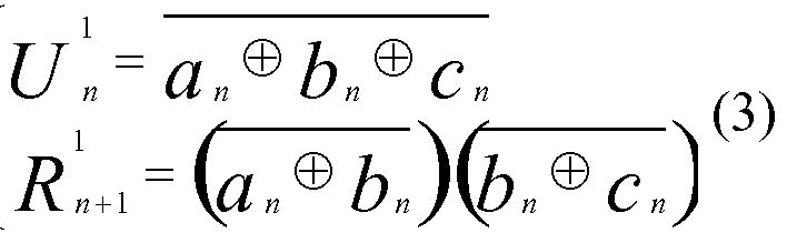


Les équations (1) pour une itération d'indice 1 par exemple, à savoir :Equations (1) for an iteration of index 1 for example, namely:


Ainsi, pour une itération d'indice i quelconque, on obtient les équations génériques (5) suivantes :Thus, for an iteration of any index i, we obtain the following generic equations (5):

Cette variante de module d'accumulation 600 permet, sur le même principe que le module d'accumulation de la figure 1 et pour un rang de bit n donné, d'additionner aux signaux d'estimation U1 et de correction H1, issus d'une itération i, un nombre binaire standard C et de fournir de nouveau un résultat sous forme binaire redondante, à savoir un signal d'estimation U1+1 et de correction H1+1 d'itération d'indice i+1.
Selon cette variante d'architecture du module d'accumulation, il est possible de générer en sortie du module 600 une valeur du bit de rang n du signal d'estimation U1+1 et une valeur du bit de rang n+1 du signal de correction H1+1 à partir des valeurs suivantes, obtenues lors d'une itération précédente d'indice i de l'étape d'accumulation : U'n-i une valeur du bit de rang n-1 d'un signal d'estimation U1, H1 J1 une valeur du bit de rang n du signal de correction H1 et Cn la valeur du bit de rang n d'un nombre binaire standard C.This variant of the accumulation module 600 makes it possible, on the same principle as the accumulation module of FIG. 1 and for a given rank of bit n, to add to the estimation U 1 and correction H 1 signals derived from of an iteration i, a standard binary number C and to provide again a result in redundant binary form, namely an estimation signal U 1 + 1 and correction H 1 + 1 of iteration of index i + 1 . According to this architecture variant of the accumulation module, it is possible to generate at the output of the module 600 a value of the bit of rank n of the estimation signal U 1 + 1 and a value of the bit of rank n + 1 of the signal correction coefficient H 1 + 1 from the following values, obtained during a previous iteration of index i of the accumulation step: U ' n -i a value of the bit of rank n-1 of a signal d estimation U 1 , H 1 J1 a value of the bit of rank n of the correction signal H 1 and C n the value of the bit of rank n of a standard binary number C.
Plus précisément, les valeurs et issues de l'itération précédente i, sont

 reçues par une première porte logique de type « OU Exclusif », aussi nommée porte « XOR », fournissant un signal numérique intermédiaire 601. Une deuxième porteMore precisely, the values and issues of the previous iteration i, are received by a first logic gate of the "Exclusive OR" type, also called "XOR" gate, providing an intermediate digital signal 601. A second gate
« XOR » reçoit à son tour le signal numérique intermédiaire 601 et la valeur de bit Cn du nombre binaire supplémentaire C et génère en sortie la valeur U1+1 n , dite valeur du bit de rang n du signal d'estimation U1+1, obtenue lors de d'une itération d'indice i+1."XOR" in turn receives the intermediate digital signal 601 and the bit value C n of the additional bit number C and outputs the value U 1 + 1 n , said value of the bit of rank n of the estimation signal U 1 +1 , obtained during an iteration of index i + 1.
Les valeurs UVi et Cn sont reçues en entrée par une porte « XNOR » et délivre en sortie un signal numérique intermédiaire 602. Une porte logique de type « AND » réceptionne ensuite les deux signaux intermédiaires 601 et 602 et pour délivrer un signal numérique intermédiaire 603. Enfin, la troisième porte « XOR » reçoit le signal intermédiaire 603 et la valeur Cn du nombre binaire C et délivre la valeur H1+Vi, dite valeur du bit de rang n+1 du signal de correction H1+1, obtenue lors ladite itération d'indice i+1.The UVi and C n values are inputted by an "XNOR" gate and outputs an intermediate digital signal 602. A "AND" type logic gate then receives the two intermediate signals 601 and 602 and delivers an intermediate digital signal 603. Finally, the third gate "XOR" receives the intermediate signal 603 and the value C n of the binary number C and delivers the value H 1+ Vi, said value of the bit of rank n + 1 of the correction signal H 1 + 1 , obtained during said iteration of index i + 1.
Par conséquent, les bits estimés U1+1 n et les bits corrigés H1+Vi obtenus lors d'une itération d'indice i+1 sont déterminés à partir des équations génériques suivantes (5) :Therefore, the estimated bits U 1 + 1 n and the corrected bits H 1+ Vi obtained during an iteration of index i + 1 are determined from the following generic equations (5):

U1+1 J1 : une valeur du bit de rang n dudit signal d'estimation U1+1, avec 0 ≤ n ≤ N-I, obtenue lors d'une itération d'indice i+1 ;
U'n : une valeur du bit de rang n d'un signal d'estimation U1, obtenue lors d'une itération précédente d'indice i si i > 0, ou une valeur d'initialisation déterminée U°n du bit de rang n d'un signal d'estimation U1 si i = 0 ;U 1 + 1 J1 : a value of the bit of rank n of said estimation signal U 1 + 1 , with 0 ≤ n ≤ NI, obtained during an iteration of index i + 1; U ' n : a value of the bit of rank n of an estimation signal U 1 , obtained during a previous iteration of index i if i> 0, or a determined initialization value U ° n of the bit of rank n of an estimation signal U 1 if i = 0;
UVi : une valeur du bit de rang n-1 dudit signal d'estimation U1, obtenue lors d'une itération précédente d'indice i si n > 0 et si i > 0, ou une valeur d'initialisation déterminée U°n_i du bit de rang n-1 dudit signal d'estimation U1 si n > 0 et si i = 0, ou une valeur d'initialisation prédéterminée d'un bit fictif de rang n-1 dudit signal d'estimation U1 si n = 0 ; H1 J1 : une valeur du bit de rang n d'un second signal de correction H1, obtenue lors de l'itération précédente d'indice i ; H1+1 J1+I : une valeur du bit de rang n+1 dudit second signal de correction H1+1, obtenue lors l'itération d'indice i+1 ;UVi: a value of the bit of rank n-1 of said estimation signal U 1 , obtained during a previous iteration of index i if n> 0 and if i> 0, or a determined initialization value U ° n _i of the bit of rank n-1 of said estimation signal U 1 if n> 0 and if i = 0, or a predetermined initialization value of a notional bit of rank n-1 of said estimation signal U 1 if n = 0; H 1 J1 : a value of the bit of rank n of a second correction signal H 1 , obtained during the previous iteration of index i; H 1 + 1 J1 + I : a value of the bit of rank n + 1 of said second correction signal H 1 + 1 obtained during the iteration of index i + 1;
Cn : une valeur du bit de rang n d'un nombre binaire d'entrée C compris dans ladite pluralité de nombres binaires d'entrée et pris en compte dans la addition lors de l'itération d'indice i+1 de l'étape d'accumulation.C n : a value of the bit of rank n of an input bit number C included in the said plurality of input binary numbers and taken into account in the addition during the iteration of index i + 1 of the accumulation stage.
Il est clair que d'autres architectures logiques (différentes de celle de la figure 6) peuvent aisément être envisagées par l'homme du métier pour la mise en œuvre des équations génériques (5), tout en restant dans le cadre de la présente invention. On présente à présent, en relation avec la figure 7, une architecture logique d'un module d'initialisation 700 susceptible d'être mis en œuvre par la variante de réalisation de la figure 6 d'un module d'initialisation selon un mode de réalisation particulier mettant en œuvre l'étape d'initialisation du procédé selon l'invention.It is clear that other logical architectures (different from that of FIG. 6) can easily be envisaged by those skilled in the art for the implementation of the generic equations (5), while remaining within the scope of the present invention. . We now present, in relation with FIG. 7, a logic architecture of an initialization module 700 that can be implemented by the variant embodiment of FIG. 6 of an initialization module according to a particular embodiment implementing the initialization step of the method according to the invention.
Le module d'initialisation 700 comprend dans un premier sous-module 701, appelé module de pré-calcul, et un second sous-module 702, appelé module d'accumulation initial. Plus précisément, le module de pré-calcul 701 présente, à la différence du module d'initialisation 200 de la figure 2, une seule porte logique de type « INV » apte à recevoir la valeur de bit de rang n d'entrées an et générant en sortie une valeur initiale de bit de rang n U°n. En effet, en reprenant les équations (4) et en posant les égalités suivantes pour le module de pré-calcul 701, à savoir : avec

 les équations du module de pré-calcul peuvent être simplifiées :
 -The initialization module 700 comprises in a first sub-module 701, called the pre-calculation module, and a second sub-module 702, called the initial accumulation module. More precisely, the pre-calculation module 701 has, unlike the initialization module 200 of FIG. 2, a single logic gate of the "INV" type able to receive the bit value of rank n of inputs n and outputting an initial value of bit of rank n U ° n . Indeed, by taking again the equations (4) and by putting the following equalities for the module of precalculation 701, namely: with the equations of the pre-calculation module can be simplified: -
Dans cette architecture, le module de pré-calcul 701 est situé en amont du module d'accumulation initial 702. Ce dernier, tel que décrit à la figure 6, permet d'ajouter la valeur du bit de rang n d'un nombre binaire supplémentaire noté Cn aux valeurs de bit d'estimation UVi et de correction H1 J1 respectivement de rang n-1 et n.In this architecture, the pre-calculation module 701 is located upstream of the initial accumulation module 702. The latter, as described in FIG. 6, makes it possible to add the value of the bit of rank n of a binary number. further noted C n the estimation bit values UVi and correction H 1 J1 respectively of rank n-1 and n.
L'itération étant d'indice 0, les valeurs en entrée du module 702 sont donc U°n_i et H°n.The iteration being index 0, the input values of the module 702 are therefore U ° n _i and H ° n .
En outre, le principe et l'architecture du module 702 étant identique au module d'accumulation 600 de la figure 6, les valeurs obtenues en sortie du module d'initialisation sont donc incrémentées d'un indice de valeur 1. On obtient ainsi les valeurs d'estimation U1 J1 et de correction H1 J1+I respectivement de bit de rang n et n+1 définies par les équations suivantes :In addition, the principle and the architecture of the module 702 being identical to the accumulation module 600 of FIG. 6, the values obtained at the output of the initialization module are therefore incremented by a value index 1. This gives the estimation values U 1 J1 and of correction H 1 J1 + I respectively of bit of rank n and n + 1 defined by the following equations:
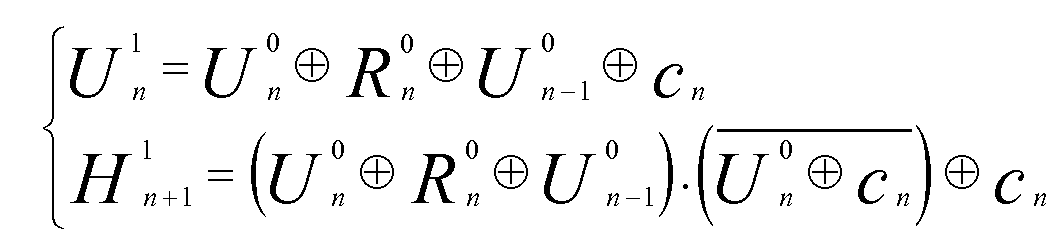

II est clair que d'autres architectures logiques (différentes de celle de la figure 7) peuvent aisément être envisagées par l'homme du métier pour la mise en œuvre des équations (6), tout en restant dans le cadre de la présente invention.It is clear that other logical architectures (different from that of FIG. 7) can easily be envisaged by those skilled in the art for the implementation of equations (6), while remaining within the scope of the present invention.
On se rapporte à présent à la figure 8 qui décrit une variante de réalisation du module d'initialisation illustré à la figure 7. Cette variante est considérée comme permettant de mettre en oeuvre l'étape d'initialisation du procédé de façon optimale.Referring now to Figure 8 which describes an alternative embodiment of the initialization module illustrated in Figure 7. This variant is considered to allow to implement the initialization step of the process optimally.
Plus particulièrement, le module d'initialisation 800 illustré sur cette figure réalise une addition de trois valeurs de bit an, bn et Cn issus de trois nombres binaires d'entrée quelconques A, B, C. Il génère en sortie une valeur
 dite valeur du bit de rang n du signal d'estimation U1 obtenu lors de l'itération 1, et une valeur R1 J1+I dite
valeur du bit de rang n+1 du signal de correction R1 obtenu également lors de l'itération 1.More particularly, the initialization module 800 illustrated in this figure performs an addition of three bit values a n , b n and C n from any three arbitrary input bits A, B, C. It generates a value said value of the bit of rank n of the estimation signal U 1 obtained during the iteration 1, and a so-called value R 1 J1 + I bit value of rank n + 1 of the correction signal R 1 also obtained during iteration 1.
dite valeur du bit de rang n du signal d'estimation U1 obtenu lors de l'itération 1, et une valeur R1 J1+I dite
valeur du bit de rang n+1 du signal de correction R1 obtenu également lors de l'itération 1.More particularly, the initialization module 800 illustrated in this figure performs an addition of three bit values a n , b n and C n from any three arbitrary input bits A, B, C. It generates a value said value of the bit of rank n of the estimation signal U 1 obtained during the iteration 1, and a so-called value R 1 J1 + I bit value of rank n + 1 of the correction signal R 1 also obtained during iteration 1.
Pour ce faire, une première porte logique de type « XNOR » reçoit les valeurs de bit de rang n des nombres binaires d'entrée an et bn et génère en sortie un signal numérique intermédiaire 801. Une porte logique de type « XOR » reçoit, quant à elle, le signal intermédiaire 801 ainsi que la valeur du bit de rang n du troisième nombre binaire Cn et délivre la valeur du bit de rang n U1 J1 de façon identique au module d'initialisation 300 de la figure 3.To do this, a first logic gate of the "XNOR" type receives the bit values of rank n from the input binary numbers a n and b n and outputs an intermediate digital signal 801. A logic gate of the "XOR" type receives, meanwhile, the intermediate signal 801 and the value of the bit of rank n of the third binary number C n and delivers the value of the bit of rank n U 1 J1 identically to the initialization module 300 of Figure 3 .
En outre, une seconde porte logique de type « XOR » reçoit les valeurs de bit de rang n bn et Cn et génère en sortie un deuxième signal numérique intermédiaire 802. La porte « AND » reçoit, quant à elle, les deux signaux numériques intermédiaires respectivement 801 et 802 et génère un troisième signal intermédiaire 803. Ce dernier est utilisé avec la valeur Cn au moyen d'une troisième porte « XOR » de façon à fournir la valeur H1 J1+I de rang n+1. On présente à présent, en relation avec la figure 9, un schéma fonctionnel d'un additionneur multi-opérandes en parallèle selon un mode de réalisation particulier conforme à l'invention. Plus précisément, cet additionneur réalise l'addition de sept nombres binaires notés El à E7, chaque nombre binaire étant exprimé sur 16 bits.In addition, a second logic gate of the "XOR" type receives the bit values of rank nb n and C n and outputs a second intermediate digital signal 802. The "AND" gate receives, for its part, the two digital signals intermediate 801 and 802 respectively and generates a third intermediate signal 803. The latter is used with the value C n by means of a third gate "XOR" so as to provide the value H 1 J1 + I of rank n + 1. FIG. 9 shows a functional diagram of a multi-operand adder in parallel according to a particular embodiment in accordance with the invention. More precisely, this adder performs the addition of seven binary numbers denoted El to E7, each binary number being expressed on 16 bits.
Dans ce mode de réalisation particulier, on présente un premier étage de calcul, constitué du dispositif d'initialisation 400, tel que décrit précédemment en relation avec la figure 3, qui calcule la somme de trois nombres binaires El, E2 et E3 et permet de fournir en sortie les deux signaux d'estimation U1O-15 et de correction R1I-I5, d'itération i=l, représentés sous une forme redondante de type « U/R ».In this particular embodiment, a first calculation stage consisting of the initialization device 400, as described previously in relation with FIG. 3, which calculates the sum of three binary numbers E1, E2 and E3 and allows outputting the two estimation signals U 1 O -15 and correction signals R 1 II 5 , with iteration i = 1, represented in a redundant form of the "U / R" type.
Un deuxième étage de calcul constitué du dispositif d'accumulation 500, tel que décrit précédemment en relation avec la figure 5, reçoit en entrée les signaux d'estimation U1O-I5 et de correction R1I-I5 issus du dispositif 400 précédent (i=l) et un nombre binaire supplémentaire E4 sur 16 bits. Ce deuxième étage génère en sortie deux signaux d'estimation uVis et de correction R2i_i5, d'itération d'indice 2 et également représentés sous une forme redondante de type « U/R ». De la même manière, trois autres étages 500 sont ajoutés afin de pouvoir sommer à chaque étage de calcul (c'est-à- dire à chaque itération d'indice i), un des trois nombres binaires supplémentaires
restants, à savoir E5 (pour l'itération d'indice 3), E6 (pour l'itération d'indice 4) et E7 (pour l'itération d'indice 5).A second calculation stage consisting of the accumulation device 500, as previously described in relation with FIG. 5, receives as input the estimation signals U 1 OI 5 and correction signals R 1 II 5 coming from the preceding device 400 (i = 1) and an additional 16 bit E4 bit number. This second stage generates as output two uVis estimation and correction signals R 2 i_i 5 , of index iteration 2 and also represented in a redundant form of the "U / R" type. In the same manner, three further stages 500 are added in order to be able to add to each calculation stage (i.e. to each iteration of index i), one of the three additional binary numbers. remaining, namely E5 (for index iteration 3), E6 (for index iteration 4) and E7 (for index iteration 5).
Au final, les derniers signaux d'estimation
 et de correction R5i_i5 issus dernier étage (itération d'indice 5) sont reçus par un additionneur 901 de type « Carry- Look-Ahead » ou « Ripple-Carry » adapté de façon à obtenir, à partir de signaux représentés sous une forme binaire redondante de type « LVR », le résultat final S0-15 en forme binaire standard des sept nombres binaires additionnés. Le détail de calcul de cette somme finale est décrit dans le brevet international WO2007122319 (TORNO).In the end, the latest estimation signals and correction R 5 i_i5 from last stage (index iteration 5) are received by a adder 901 type "Carry-Look-Ahead" or "Ripple-Carry" adapted to obtain, from signals represented in a redundant bit type "LVR", the final result S 0-15 in standard binary form of the seven binary numbers added. The calculation detail of this final sum is described in the international patent WO2007122319 (TORNO).
Il est à noter que les valeurs
 sont les valeurs d'initialisation prédéterminée du bit de rang n = 0 du signal de correction et valeurs d'initialisation déterminée qui sont, dans ce cas précis, égaux à 1. En effet, chaque module générant un signal de correction R'n+ide rang n+1 pour une itération d'indice i, le signal de correction de rang n = 0 d'itération i n'est donc pas existant. Il en est de même avec le bit fictif U1. i . En outre, il est à noter que les valeurs de bit de rang 16, notée
 ne sont pas utilisées dans ce mode de réalisation particulier. En effet, la dynamique d'expression sur 16 bits est suffisante pour que l'accumulation des sept nombres binaires puisse s'effectuer sans retenue de dépassement (ou « overflow » en anglais).It should be noted that the values are the predetermined initialization values of the bit of rank n = 0 of the correction signal and determined initialization values which are, in this case, equal to 1. Indeed, each module generating a correction signal R ' n + ide rank n + 1 for an iteration of index i, the correction signal of rank n = 0 of iteration i is therefore not existing. It is the same with the fictitious bit U 1 . i. In addition, it should be noted that bit values of rank 16, noted are not used in this particular embodiment. Indeed, the dynamics of 16-bit expression is sufficient for the accumulation of the seven binary numbers can be carried out without overflow restraint (or "overflow" in English).
On présente désormais, en relation avec la figure 10, un schéma fonctionnel d'un additionneur multi-opérandes séquentiel selon un mode de réalisation particulier conforme à l'invention. Plus particulièrement, cet additionneur réalise l'addition de sept nombres binaires notés El à E7, de 16 bits chacun. Il peut être utilisé notamment dans le cadre du filtrage numérique, par exemple.A block diagram of a sequential multi-operand adder according to a particular embodiment according to the invention is now presented in relation to FIG. More particularly, this adder performs the addition of seven binary numbers denoted El to E7, of 16 bits each. It can be used especially in the context of digital filtering, for example.
Dans ce mode de réalisation particulier, un seul dispositif d'accumulation 500 (tel que décrit à la figure 5) est nécessaire et un registre 1020 stocke tous les résultats intermédiaires de l'accumulation. Le calcul s'effectue donc de manière séquentielle pour i itérations, i variant de 1 jusqu'à 7.In this particular embodiment, only one accumulation device 500 (as depicted in FIG. 5) is needed and a register 1020 stores all the intermediate results of the accumulation. The calculation is therefore carried out sequentially for i iterations, i ranging from 1 to 7.
Dans un premier temps, le registre 1030 contenant les signaux UVis et de correction R°i_i5 est initialisé afin que chaque valeur de bit n U°0-i5 et R°i_i6 ait la valeur 1, ainsi que
 Dans un second temps, la commande de sélection du multiplexeur 1010 sélectionne le nombre binaire d'entrée El et un calcul d'itération d'indice 1 (i+1 avec i = 0) est alors effectué. Le dispositif d'accumulation 500, constitué de 16 modules d'accumulation, additionne les entrées
 sur 16 bits et El pour générer les valeurs U1O-Is et R1I-I6. Les valeurs précédemment obtenues sont ensuite présentées à l'entrée du registre 32 bits et mémorisées par l'action de l'horloge. Puis, la commande de sélection du multiplexeur sélectionne l'entrée suivante E2.Initially, the register 1030 containing Uvis signals and R ° i_i5 correction is initialized so that each bit value U n ° i 0- 5 and R ° i_i6 has the value 1, and In a second step, the selection control of the multiplexer 1010 selects the input binary number E1 and an iteration calculation of index 1 (i + 1 with i = 0) is then performed. The accumulation device 500, consisting of 16 storage modules, adds the inputs on 16 bits and El to generate the values U 1 O-Is and R 1 II 6 . The previously obtained values are then presented at the input of the 32-bit register and stored by the action of the clock. Then, the selection control of the multiplexer selects the next input E2.
Il est à noter que les valeurs U1-! et R1O sont toujours égales à 1 quelle que soit l'étape de calcul d'accumulation, en d'autres termes quelle que soit la valeur d'itération i.It should be noted that the values U 1 -! and R 1 O are always equal to 1 regardless of the accumulation calculation step, in other words regardless of the iteration value i.
Les actions de l'étape précédente sont ensuite répétées pour i allant 2 à 7 afin de pouvoir additionner toutes les entrées E2 à E7 aux résultats intermédiaires
 1 \ 16 à
 pour obtenir les résultats intermédiaires
 et
et
 The actions of the preceding step are then repeated for i ranging from 2 to 7 in order to be able to add all the inputs E2 to E7 to the intermediate results. 1 \ 16 to to get intermediate results and
I6- Finalement, un calcul final est effectué au moyen d'un additionneur . Le résultat intermédiaire U7 0-i5 et R7i_i5 correspondant à la dernière itération (i=7) est présenté à l'entrée d'un additionneur 901 de type « Carry-Look-Ahead » ou de type « Ripple- Carry » sur 16 bits adapté pour prendre en entrée une forme binaire redondante« U/R » tels que décrits dans le brevet international WO2007122319 (TORNO). Les bits U7_i et R7o sont initialisés à 1. L'additionneur 901 permet ainsi de déterminer le résultat final sous forme binaire standard de la somme des sept nombres binaires El à E7.I 6 - Finally, a final calculation is performed by an adder. The intermediate result U 7 0- 5 and R 7 i_i5 corresponding to the last iteration (i = 7) is presented at the input of a adder 901 type "Carry-Look-Ahead" or type "Ripple-Carry 16 bits adapted to take as input a redundant "U / R" binary form as described in the international patent WO2007122319 (TORNO). The bits U 7 _i and R 7 o are initialized to 1. The adder 901 thus makes it possible to determine the final result in standard binary form of the sum of the seven binary numbers E1 to E7.
Il est à noter que les valeurs de bit de rang 16, notée R1I6, ne sont également pas utilisées dans ce mode de réalisation particulier. En effet, la dynamique d'expression sur 16 bits est suffisante pour que l'accumulation des sept nombres binaires puisse s'effectuer sans retenue de dépassement (ou « overflow » en anglais).It should be noted that the bit values of rank 16, denoted R 1 I 6 , are also not used in this particular embodiment. Indeed, the dynamics of 16-bit expression is sufficient for the accumulation of the seven binary numbers can be carried out without overflow restraint (or "overflow" in English).
La figure 11 illustre un exemple d'un calcul numérique d'une sommation de sept nombres binaires, effectué par l'additionneur multi-opérandes de la figure 9. Chaque ligne de calcul est exprimée sur 16 bits de données et chaque signal d'estimation U et de correction R est illustré pour chacune des itérations du procédé conformément à l'invention.
Le résultat binaire final S est également présenté sur 16 bits de données, ce dernier ayant été obtenu sous forme binaire standard.FIG. 11 illustrates an example of a numerical calculation of a summation of seven binary numbers, carried out by the multi-operand adder of FIG. 9. Each calculation line is expressed on 16 bits of data and each estimation signal U and correction R is illustrated for each of the iterations of the method according to the invention. The final bit result S is also presented on 16 bits of data, the latter having been obtained in standard binary form.
On notera que l'invention ne se limite pas à une implantation purement matérielle mais qu'elle peut aussi être mise en œuvre sous la forme d'une séquence d'instructions d'un programme informatique ou toute forme mixant une partie matérielle et une partie logicielle. Dans le cas où l'invention est implantée partiellement ou totalement sous forme logicielle, la séquence d'instructions correspondante pourra être stockée dans un moyen de stockage amovible (tel que par exemple une disquette, unIt should be noted that the invention is not limited to a purely material implantation but that it can also be implemented in the form of a sequence of instructions of a computer program or any form mixing a material part and a part software. In the case where the invention is implemented partially or totally in software form, the corresponding instruction sequence may be stored in a removable storage means (such as for example a diskette, a
CD-ROM ou un DVD-ROM) ou non, ce moyen de stockage étant lisible partiellement ou totalement par un ordinateur ou un microprocesseur.
CD-ROM or a DVD-ROM) or not, this storage means being partially or completely readable by a computer or a microprocessor.
Annexe 1 : Passage de l'art antérieur au module d'initialisation sous forme « U/R »Appendix 1: Transition from the prior art to the initialization module in "U / R" form
Soient A, B et C les trois nombres, exprimés sur N bits, que l'on souhaite additionner :Let A, B and C be the three numbers, expressed on N bits, which we wish to add:

De façon classique, il est possible d'effectuer dans un premier temps une somme de ces trois nombres binaires et obtenir un résultat de la forme standard « Carry-Save » au moyen d'un réseau d'additionneurs de type « full-adder ». Ce réseau d'additionneurs permet de générer en sortie une somme partielle, et une retenue partielle, telles que :Conventionally, it is possible to initially perform a sum of these three binary numbers and obtain a result of the standard form "Carry-Save" by means of a network of adder adder type adder . This network of adders makes it possible to generate as output a partial sum, and a partial hold, such that:

De cette façon, on obtient les nombres U et R suivants :In this way, we obtain the following numbers U and R:

En substituant les valeurs de
 n et C
 par leurs expressions en
 ? on obtient :By substituting the values of n and C by their expressions in ? we get:


Annexe 2 : Passage du module d'initialisation sous forme « U/R » au module d'accumulation sous forme « U/R »Annex 2: Transfer of the initialisation module in "U / R" form to the accumulation module in "U / R" form
En partant des mêmes équations que précédemment, il est possible de construire un module d'accumulation permettant de recevoir en entrées un signal d'estimation U, un signal de correction R et un nombre binaire standard c. Le détail des calculs permettant de déterminer le résultat sous forme redondante « U/R » sont exposés ci- après.Starting from the same equations as above, it is possible to construct an accumulation module for receiving as inputs an estimation signal U, a correction signal R and a standard binary number c. The details of the calculations for determining the result in redundant "U / R" form are described below.
À partir des équations (3) précitées, on peut construire à partir des nombres binaires A et B, par exemple, une forme initiale exprimée de la façon suivante :From equations (3) above, it is possible to construct from the binary numbers A and B, for example, an initial form expressed as follows:
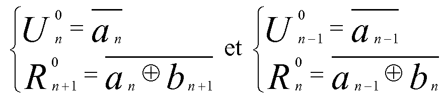
On peut alors déduire les valeurs an et bn, à savoir :We can then deduce the values a n and b n , namely:

Puis, en substituant les valeurs de an et bn dans le système d'équations (1), on obtient l'expression suivante :Then, substituting the values of a n and b n in the system of equations (1), we obtain the following expression:

Après développement et simplification, on obtient les deux expressions suivantes :After development and simplification, we obtain the following two expressions:


Claims
1. Procédé d'addition permettant d'additionner une pluralité de nombres binaires d'entrée, de N bits chacun, caractérisé en ce qu'il comprend au moins une itération, d'indice i+1 avec i > 0, d'une étape d'accumulation permettant de générer un signal d'estimation U1+1 sur N bits et un premier R1+1 ou second H1+1 signal de correction sur N bits,1. Addition method for adding a plurality of input binary numbers, of N bits each, characterized in that it comprises at least one iteration, of index i + 1 with i> 0, of a accumulation step for generating an estimation signal U 1 + 1 on N bits and a first R 1 + 1 or second H 1 + 1 correction signal on N bits,
* selon les équations suivantes :* according to the following equations:


U1+1 n : une valeur du bit de rang n dudit signal d'estimation U1+1, avec 0 ≤ n ≤ N-I, obtenue lors de ladite itération d'indice i+1 ;U 1 + 1 n : a value of the bit of rank n of said estimation signal U 1 + 1 , with 0 ≤ n ≤ NI, obtained during said iteration of index i + 1;
U'n : une valeur du bit de rang n d'un signal d'estimation U1, obtenue lors d'une itération précédente d'indice i si i > 0, ou une valeur d'initialisation déterminéeU ' n : a value of the bit of rank n of an estimation signal U 1 , obtained during a previous iteration of index i if i> 0, or a determined initialization value
U°n du bit de rang n d'un signal d'estimation U1 si i = 0 ; U'n-i : une valeur du bit de rang n-1 dudit signal d'estimation U1, obtenue lors d'une itération précédente d'indice i si n > 0 et si i > 0, ou une valeur d'initialisation déterminée U°n_i du bit de rang n-1 dudit signal d'estimation U1 si n > 0 et si i = 0, ou une valeur d'initialisation prédéterminée d'un bit fictif de rang n-1 dudit signal d'estimation U1 si n = 0 ; R1 I1 : une valeur du bit de rang n d'un premier signal de correction R1, obtenue lors d'une itération précédente d'indice i si n > 0, ou une valeur d'initialisation prédéterminée du bit de rang n dudit premier signal de correction R1 si n = 0 ; R1+1 I1+I : une valeur du bit de rang n+1 dudit premier signal de correction R1+1, obtenue lors ladite itération d'indice i+1 ; H1 J1 : une valeur du bit de rang n d'un second signal de correction H1, obtenue lors d'une itération précédente d'indice i ; H1+1 J1+I : une valeur du bit de rang n+1 dudit second signal de correction H1+1, obtenue lors ladite itération d'indice i+1 ; Cn : une valeur du bit de rang n d'un nombre binaire d'entrée C compris dans ladite pluralité de nombres binaires d'entrée et pris en compte dans ladite addition lors de ladite itération d'indice i+1 de ladite étape d'accumulation, le signal d'estimation U1 et le premier signal de correction R1 ou le second signal de correction H1 représentant une somme d'au moins deux nombres binaires en forme redondante, le signal d'estimation U1+1 et le premier signal de correction R1+1 ou le second signal de correction H1+1 représentant la somme desdites au moins deux nombres binaires en forme redondante et du nombre binaire c.U ° n of the bit of rank n of an estimation signal U 1 if i = 0; U ' n -i: a value of the bit of rank n-1 of said estimation signal U 1 , obtained during a previous iteration of index i if n> 0 and if i> 0, or an initialization value determined U ° n _i of the bit of rank n-1 of said estimation signal U 1 if n> 0 and if i = 0, or a predetermined initialization value of a notional bit of rank n-1 of said signal of U 1 estimate if n = 0; R 1 I1 : a value of the bit of rank n of a first correction signal R 1 , obtained during a previous iteration of index i if n> 0, or a predetermined initialization value of the bit of rank n of said first correction signal R 1 if n = 0; R 1 + 1 I1 + I : a value of the bit of rank n + 1 of said first correction signal R 1 + 1 , obtained during said iteration of index i + 1; H 1 J1 : a value of the bit of rank n of a second correction signal H 1 , obtained during a previous iteration of index i; H 1 + 1 J1 + I : a value of the bit of rank n + 1 of said second correction signal H 1 + 1 obtained during said iteration of index i + 1; C n : a value of the bit of rank n of an input bit number C included in said plurality of input binary numbers and taken into account in said addition during said iteration of index i + 1 of said step d accumulation, the estimation signal U 1 and the first correction signal R 1 or the second correction signal H 1 representing a sum of at least two binary numbers in redundant form, the estimation signal U 1 + 1 and the first correction signal R 1 + 1 or the second correction signal H 1 + 1 representing the sum of said at least two binary numbers in redundant form and the binary number c.
2. Procédé selon la revendication 1, caractérisé en ce que l'itération d'indice 1 de ladite étape d'accumulation est remplacée par une étape d'initialisation permettant de générer un signal d'estimation U1 sur N bits et un premier R1 ou second H1 signal de correction sur N bits, * selon les équations suivantes, avec 0 ≤ n ≤ N-I :2. Method according to claim 1, characterized in that the index iteration 1 of said accumulation step is replaced by an initialization step for generating an estimation signal U 1 on N bits and a first R 1 or second H 1 correction signal on N bits, * according to the following equations, with 0 ≤ n ≤ NI:


3. Procédé selon la revendication 1, caractérisé en ce qu'il comprend les étapes suivantes : sélection d'un premier nombre binaire d'entrée compris dans ladite pluralité de nombres binaires d'entrée ; obtention de valeurs d'initialisation prédéterminées pour :3. Method according to claim 1, characterized in that it comprises the following steps: selecting a first input binary number included in said plurality of input binary numbers; obtaining predetermined initialization values for:
* chacun des N bits d'un signal d'estimation U0, * chacun des N bits d'un signal de correction R0,each of the N bits of an estimation signal U 0 , each of the N bits of a correction signal R 0 ,
* un bit fictif de rang -1 dudit signal d'estimation U0 ; itération d'indice 1 de ladite étape d'accumulation avec, comme signaux d'entrée, ledit premier nombre binaire d'entrée et lesdites valeurs d'initialisation prédéterminées, permettant de générer un signal d'estimation U1 sur N bits et un premier R1 signal de correction sur N bits ; tant que ladite pluralité de nombres binaires d'entrée n'ont pas été pris en compte dans ladite addition :a fictitious bit of rank -1 of said estimation signal U 0 ; index iteration 1 of said accumulation step with, as input signals, said first input bit number and said predetermined initialization values, for generating an estimation signal U 1 on N bits and a first R 1 correction signal on N bits; as long as said plurality of input binary numbers have not been taken into account in said addition:
* sélection d'un nouveau nombre binaire d'entrée compris dans ladite pluralité de nombres binaires d'entrée et non déjà sélectionné ; * itération d'indice i+1, avec i > 0, de ladite étape d'accumulation avec, comme signaux d'entrée, ledit nouveau nombre binaire d'entrée, les signaux U1 et R1 générés lors de l'itération d'indice i de ladite étape d'accumulation, une valeur d'initialisation prédéterminée U'_i d'un bit fictif de rang -1 dudit signal d'estimation U1, et une valeur d'initialisation prédéterminée R'o du bit de rang 0 dudit premier signal de correction R1.selecting a new input binary number included in said plurality of input binary numbers and not already selected; * iteration of index i + 1, with i> 0, of said accumulation step with, as input signals, said new input bit number, the signals U 1 and R 1 generated during the iteration of i index of said accumulation step, a predetermined initialization value U'_i of a fictitious bit of rank -1 of said estimation signal U 1 , and a predetermined initialization value R'o of the rank bit 0 of said first correction signal R 1 .
4. Procédé selon la revendication 1, caractérisé en ce qu'il comprend les étapes suivantes : sélection d'un premier nombre binaire d'entrée compris dans ladite pluralité de nombres binaires d'entrée ; - obtention de valeurs d'initialisation prédéterminées pour :4. Method according to claim 1, characterized in that it comprises the following steps: selecting a first input binary number included in said plurality of input binary numbers; obtaining predetermined initialization values for:
* chacun des N bits d'un signal d'estimation U0, * chacun des N bits d'un signal de correction H0, itération d'indice 1 de ladite étape d'accumulation avec, comme signaux d'entrée, ledit premier nombre binaire d'entrée et lesdites valeurs d'initialisation prédéterminées, permettant de générer un signal d'estimation U1 sur N bits et un second H1 signal de correction sur N bits ; tant que ladite pluralité de nombres binaires d'entrée n'ont pas été pris en compte dans ladite addition :each of the N bits of an estimate signal U 0 , each of the N bits of a correction signal H 0 , index iteration 1 of said accumulation step with, as input signals, said first input binary number and said predetermined initialization values, making it possible to generating an estimation signal U 1 on N bits and a second H 1 correction signal on N bits; as long as said plurality of input binary numbers have not been taken into account in said addition:
* sélection d'un nouveau nombre binaire d'entrée compris dans ladite pluralité de nombres binaires d'entrée et non déjà sélectionné ; * itération d'indice i+1, avec i > 0, de ladite étape d'accumulation avec, comme signaux d'entrée, ledit nouveau nombre binaire d'entrée, les signaux U1 et H1 générés lors de l'itération d'indice i de ladite étape d'accumulation, et une valeur d'initialisation prédéterminée R'o du bit de rang 0 dudit premier signal de correction R1. selecting a new input binary number included in said plurality of input binary numbers and not already selected; an iteration of index i + 1, with i> 0, of said accumulation step with, as input signals, said new input bit number, the signals U 1 and H 1 generated during the iteration of i index of said accumulation step, and a predetermined initialization value R'o of the rank bit 0 of said first correction signal R 1 .
5. Dispositif d'addition permettant d'additionner une pluralité de nombres binaires d'entrée, de N bits chacun, caractérisé en ce qu'il comprend au moins un bloc d'accumulation permettant, à chaque fois qu'il est activé, d'effectuer une itération, d'indice i+1 avec i > 0, d'un mécanisme d'accumulation, chaque bloc d'accumulation comprenant : * des premiers moyens d'estimation, permettant de générer un signal d'estimation5. Addition device for adding a plurality of input binary numbers, of N bits each, characterized in that it comprises at least one accumulation block allowing, each time it is activated, iterating, of index i + 1 with i> 0, of an accumulation mechanism, each accumulation block comprising: * first estimation means, making it possible to generate an estimation signal
U1+1 sur N bits, et des premiers moyens de correction, permettant de générer un premier signal de correction R1+1 sur N bits, lesdits premiers moyens d'estimation et lesdits premiers moyens de correction comprenant des moyens de mise en œuvre des équations suivantes :U 1 + 1 on N bits, and first correction means, for generating a first correction signal R 1 + 1 on N bits, said first estimation means and said first correction means comprising means of implementation the following equations:

* ou des seconds moyens d'estimation, permettant de générer un signal d'estimation U1+1 sur N bits, et des seconds moyens de correction, permettant de générer un second signal de correction H1+1 sur N bits, lesdits seconds moyens d'estimation et lesdits seconds moyens de correction comprenant des moyens de mise en œuvre des équations suivantes :  avec :* or second estimation means, for generating an estimation signal U 1 + 1 on N bits, and second correction means, for generating a second correction signal H 1 + 1 on N bits, said second estimation means and said second correction means comprising means for implementing the following equations: with:
U1 1+1 une valeur du bit de rang n dudit signal d'estimation U τl1+ 1 , avec 0 ≤ n ≤ N-I, obtenue lors de ladite itération d'indice i+1 ; U'n : une valeur du bit de rang n d'un signal d'estimation U1, obtenue lors d'une itération précédente d'indice i si i > 0, ou une valeur d'initialisation déterminéeU 1 1 + 1 a value of the bit of rank n of said estimation signal U τl 1 + 1, with 0 ≤ n ≤ NI, obtained during said iteration of index i + 1; U ' n : a value of the bit of rank n of an estimation signal U 1 , obtained during a previous iteration of index i if i> 0, or a determined initialization value
U°n du bit de rang n d'un signal d'estimation U1 si i = 0 ; UVi : une valeur du bit de rang n-1 dudit signal d'estimation U1, obtenue lors d'une itération précédente d'indice i si n > 0 et si i > 0, ou une valeur d'initialisation déterminée U°n_i du bit de rang n-1 dudit signal d'estimation U1 si n > 0 et si i = 0, ou une valeur d'initialisation prédéterminée d'un bit fictif de rang n-1 dudit signal d'estimation U1 si n = 0 ;U ° n of the bit of rank n of an estimation signal U 1 if i = 0; UVi: a value of the bit of rank n-1 of said estimation signal U 1 , obtained during a previous iteration of index i if n> 0 and if i> 0, or a determined initialization value U ° n _i of the bit of rank n-1 of said estimation signal U 1 if n> 0 and if i = 0, or a predetermined initialization value of a notional bit of rank n-1 of said estimation signal U 1 if n = 0;
Rn une valeur du bit de rang n d'un premier signal de correction R1, obtenue lors d'une itération précédente d'indice i si n > 0, ou une valeur d'initialisation prédéterminée du bit de rang n dudit premier signal de correction R1 si n = 0 ; R , 11++11I1+I : une valeur du bit de rang n+1 dudit premier signal de correction R1+1, obtenue lors ladite itération d'indice i+1 ; H1 J1 : une valeur du bit de rang n d'un second signal de correction H1, obtenue lors d'une itération précédente d'indice i ; H1+1 J1+I : une valeur du bit de rang n+1 dudit second signal de correction H1+1, obtenue lors ladite itération d'indice i+1 ; Cn : une valeur du bit de rang n d'un nombre binaire d'entrée C compris dans ladite pluralité de nombres binaires d'entrée et pris en compte dans ladite addition lors de ladite itération d'indice i+1. le signal d'estimation U1 et le premier signal de correction R1 ou le second signal de correction H1 représentant une somme d'au moins deux nombres binaires en forme redondante, le signal d'estimation U1+1 et le premier signal de correction R1+1 ou le second signal de correction H1+1 représentant la somme desdites au moins deux nombres binaires en forme redondante et du nombre binaire c.Rn a value of the bit of rank n of a first correction signal R 1 , obtained during a previous iteration of index i if n> 0, or a predetermined initialization value of the bit of rank n of said first signal of correction R 1 if n = 0; R, 1 1 + + 1 1 I1 + I : a value of the bit of rank n + 1 of said first correction signal R 1 + 1 , obtained during said iteration of index i + 1; H 1 J1 : a value of the bit of rank n of a second correction signal H 1 , obtained during a previous iteration of index i; H 1 + 1 J1 + I : a value of the bit of rank n + 1 of said second correction signal H 1 + 1 obtained during said iteration of index i + 1; C n : a value of the bit of rank n of an input bit number C included in said plurality of input binary numbers and taken into account in said addition during said iteration of index i + 1. the estimation signal U 1 and the first correction signal R 1 or the second correction signal H 1 representing a sum of at least two binary numbers in redundant form, the estimation signal U 1 + 1 and the first signal of correction R 1 + 1 or the second correction signal H 1 + 1 representing the sum of said at least two binary numbers in redundant form and the binary number c.
6. Dispositif selon la revendication 5 , caractérisé en ce que ledit bloc d'accumulation comprend, pour chaque bit n, un sous-bloc d'accumulation lui-même comprenant : une première porte logique XOR recevant ladite valeur UVi du bit de rang n-1 et d'indice i et ladite valeur R'n du bit de rang n et d'indice i, et générant un premier signal intermédiaire ; une deuxième porte logique XOR recevant ledit premier signal intermédiaire et ladite valeur U'n du bit de rang n et d'indice i, et générant un deuxième signal intermédiaire ; une troisième porte logique XOR recevant ledit deuxième signal intermédiaire et ladite valeur du bit de rang n d'un nombre binaire d'entrée C, et générant ladite valeur U1+1 n du bit de rang n dudit signal d'estimation U1+1 pour l'itération d'indice i+1 ; une quatrième porte logique XOR recevant ladite valeur U'n du bit de rang n et d'indice i et ladite valeur Cn du bit de rang n d'un nombre binaire d'entrée C, et générant un troisième signal intermédiaire ; et une porte logique AND recevant ledit troisième signal intermédiaire et ledit deuxième signal intermédiaire, et générant ladite valeur R1+Vi du bit de rang n+1 dudit premier signal de correction R1+1 pour l'itération d'indice i+1.6. Device according to claim 5, characterized in that said accumulation block comprises, for each bit n, an accumulation sub-block itself comprising: a first logic gate XOR receiving said value UVi of the bit of rank n -1 and index i and said value R ' n of the bit of rank n and index i, and generating a first intermediate signal; a second XOR logic gate receiving said first intermediate signal and said U'n value of the bit of rank n and index i, and generating a second intermediate signal; a third logic gate XOR receiving said second intermediate signal and said value of the bit of rank n of a binary input number C, and generating said value U 1 + 1 n of the bit of rank n of said estimation signal U 1+ 1 for the iteration of index i + 1; a fourth logic gate XOR receiving said value U'n of the bit of rank n and index i and said value C n of the bit of rank n of a binary input number C, and generating a third intermediate signal; and a logic gate AND receiving said third intermediate signal and said second intermediate signal, and generating said value R 1+ Vi of the bit of rank n + 1 of said first correction signal R 1 + 1 for the iteration of index i + 1 .
7. Dispositif selon la revendication 5 , caractérisé en ce que ledit bloc d'accumulation comprend, pour chaque bit n, un sous-bloc d'accumulation lui-même comprenant : - une première porte logique XOR recevant ladite valeur U'n-i du bit de rang n-1 et d'indice i et ladite valeur H'n du bit de rang n et d'indice i, et générant un premier signal intermédiaire ; une deuxième porte logique XOR recevant ledit premier signal intermédiaire et ladite valeur Cn du bit de rang n d'un nombre binaire d'entrée C, et générant ladite valeur U1+ 1 n du bit de rang n dudit signal d'estimation U1+1 pour l'itération d'indice i+1 ; une porte logique XNOR recevant ladite valeur UVi du bit de rang n-1 et d'indice i et ladite valeur Cn du bit de rang n d'un nombre binaire d'entrée C et générant un deuxième signal intermédiaire ; une porte logique AND recevant ledit premier signal intermédiaire et ledit deuxième signal intermédiaire et générant un troisième signal intermédiaire ; et une troisième porte logique XOR recevant ledit troisième signal intermédiaire et ladite valeur Cn du bit de rang n d'un nombre binaire d'entrée C et générant ladite valeur du bit de rang n+1 dudit second signal de correction H1+1 pour  l'itération d'indice i+1.7. Device according to claim 5, characterized in that said accumulation block comprises, for each bit n, an accumulation sub-block itself comprising: a first logic gate XOR receiving said value U'n-i the bit of rank n-1 and index i and said value H ' n of the bit of rank n and index i, and generating a first intermediate signal; a second logic gate XOR receiving said first intermediate signal and said value C n of the bit of rank n of a binary input number C, and generating said value U 1+ 1 n of bit of rank n of said estimation signal U 1 + 1 for the iteration of index i + 1; a logic gate XNOR receiving said value UVi of the bit of rank n-1 and index i and said value C n of the bit of rank n of a binary input number C and generating a second intermediate signal; an AND logic gate receiving said first intermediate signal and said second intermediate signal and generating a third intermediate signal; and a third logic gate XOR receiving said third intermediate signal and said value C n of the bit of rank n of a binary input number C and generating said value of the bit of rank n + 1 of said second correction signal H 1 + 1 for the iteration of index i + 1.
8. Dispositif selon la revendication 5, caractérisé en ce qu'il comprend un bloc d'initialisation comprenant :8. Device according to claim 5, characterized in that it comprises an initialization block comprising:
* des troisièmes moyens d'estimation, permettant de générer un signal d'estimation U1 sur N bits, et des troisièmes moyens de correction, permettant de générer un troisième signal de correction R1 sur N bits, lesdits troisièmes moyens d'estimation et lesdits troisièmes moyens de correction comprenant des moyens de mise en œuvre des équations suivantes, avec 0 ≤ n ≤ N-I :third estimation means for generating an estimation signal U 1 on N bits, and third correction means for generating a third correction signal R 1 on N bits, said third estimation means and said third correction means comprising means for implementing the following equations, with 0 ≤ n ≤ NI:


Cn : une valeur du bit de rang n d'un nombre binaire d'entrée C compris dans ladite pluralité de nombres binaires d'entrée et pris en compte par ledit bloc d'initialisation ; et en ce que ledit bloc d'initialisation remplace le bloc d'accumulation permettant d'effectuer l'itération d'indice 1.C n : a value of the bit of rank n of an input bit number C included in said plurality of input binary numbers and taken into account by said initialization block; and in that said initialization block replaces the accumulation block for performing the iteration of index 1.
9. Dispositif selon la revendication 8, caractérisé en ce que ledit bloc d'initialisation comprend, pour chaque bit n, un sous-bloc d'initialisation lui-même comprenant : une première porte logique XNOR recevant ladite valeur an du bit de rang n d'un nombre binaire d'entrée A et ladite valeur bn du bit de rang n d'un nombre binaire d'entrée B et générant un premier signal intermédiaire ; une porte logique XOR recevant ledit premier signal intermédiaire et ladite valeur ladite valeur Cn du bit de rang n d'un nombre binaire d'entrée C et générant ladite valeur  du bit de rang n dudit signal d'estimation U1 pour l'itération d'indice 1 ; une seconde porte logique XNOR recevant ladite valeur bn du bit de rang n d'un nombre binaire d'entrée B et ladite valeur Cn du bit de rang n d'un nombre binaire d'entrée C et générant un deuxième signal intermédiaire ; et une porte logique AND recevant lesdits premier et deuxième signaux intermédiaires et générant ladite valeur
  du bit de rang n+1 dudit signal de correction R1 pour l'itération d'indice 1.9. Device according to claim 8, characterized in that said initialization block comprises, for each bit n, an initialization sub-block itself comprising: a first logic gate XNOR receiving said value a n of the bit of rank n of an input bit number A and said value b n of the bit of rank n of a binary input number B and generating a first intermediate signal; a logic gate XOR receiving said first intermediate signal and said value said value C n of the bit of rank n of a binary input number C and generating said value bit of rank n of said estimation signal U 1 for index iteration 1; a second logic gate XNOR receiving said value b n of the bit of rank n of an input binary number B and said value C n of the bit of rank n of a binary input number C and generating a second intermediate signal; and an AND logic gate receiving said first and second intermediate signals and generating said value the bit of rank n + 1 of said correction signal R 1 for the iteration of index 1.
10. Dispositif selon la revendication 8, caractérisé en ce que ledit bloc d'initialisation comprend, pour chaque bit n, un sous-bloc d'initialisation lui-même comprenant : une porte logique XNOR recevant ladite valeur an du bit de rang n d'un nombre binaire d'entrée A et ladite valeur bn du bit de rang n d'un nombre binaire d'entrée B et générant un premier signal intermédiaire ; une première porte logique XOR recevant ledit premier signal intermédiaire et ladite valeur ladite valeur Cn du bit de rang n d'un nombre binaire d'entrée C et générant ladite valeur du bit de rang n dudit signal d'estimation U1 pour l'itération d'indice 1 ; une deuxième porte logique XOR recevant ladite valeur bn du bit de rang n d'un nombre binaire d'entrée B et ladite valeur Cn du bit de rang n d'un nombre binaire d'entrée C et générant un deuxième signal intermédiaire ; une porte logique AND recevant lesdits premier et deuxième signaux intermédiaires et générant un troisième signal intermédiaire ; et une troisième porte logique XOR recevant ledit troisième signal intermédiaire et ladite valeur Cn du bit de rang n d'un nombre binaire d'entrée C et générant ladite valeur du bit de rang n+1 dudit second signal de correction H1 pour  l'itération d'indice 1. 10. Device according to claim 8, characterized in that said initialization block comprises, for each bit n, an initialization sub-block itself comprising: an XNOR logic gate receiving said value a n of the bit of rank n an input bit number A and said value b n of the bit of rank n of a binary input number B and generating a first intermediate signal; a first logic gate XOR receiving said first intermediate signal and said value said value C n of the bit of rank n of a binary input number C and generating said value of the bit of rank n of said estimation signal U 1 for the iteration of index 1; a second logic gate XOR receiving said value b n of the bit of rank n of a binary input number B and said value C n of the bit of rank n of a binary input number C and generating a second intermediate signal; an AND logic gate receiving said first and second intermediate signals and generating a third intermediate signal; and a third logic gate XOR receiving said third intermediate signal and said value C n of the bit of rank n of a binary input number C and generating said value of the bit of rank n + 1 of said second correction signal H 1 for the index iteration 1.
11. Dispositif selon la revendication 5, caractérisé en ce qu'il comprend : des premiers moyens de sélection, permettant de sélectionner un premier nombre binaire d'entrée compris dans ladite pluralité de nombres binaires d'entrée ; - des moyens d'obtention de valeurs d'initialisation prédéterminées pour :11. Device according to claim 5, characterized in that it comprises: first selection means for selecting a first input binary number included in said plurality of input binary numbers; means for obtaining predetermined initialization values for:
* chacun des N bits d'un signal d'estimation U0,each of the N bits of an estimate signal U 0 ,
* chacun des N bits d'un signal de correction R0,each of the N bits of a correction signal R 0 ,
* un bit fictif de rang -1 dudit signal d'estimation U0 ; des premiers moyens d'activation, permettant d'activer ledit bloc d'accumulation afin qu'il effectue l'itération d'indice 1 dudit mécanisme d'accumulation avec, comme signaux d'entrée, ledit premier nombre binaire d'entrée et lesdites valeurs d'initialisation prédéterminées, permettant de générer un signal d'estimation U1 sur N bits et un premier R1 signal de correction sur N bits ; des seconds moyens d'activation, permettant d'activer les moyens suivants, tant que ladite pluralité de nombres binaires d'entrée n'ont pas été pris en compte dans ladite addition :a fictitious bit of rank -1 of said estimation signal U 0 ; first activating means for activating said accumulation block to perform the index iteration of said accumulation mechanism with, as input signals, said first input binary number and said predetermined initialization values, for generating an estimation signal U 1 on N bits and a first R 1 correction signal on N bits; second activation means for enabling the following means, as long as said plurality of input binary numbers have not been taken into account in said addition:
* des seconds moyens sélection, permettant de sélectionner un nouveau nombre binaire d'entrée compris dans ladite pluralité de nombres binaires d'entrée et non déjà sélectionné ; * ledit bloc d'accumulation afin qu'il effectue une itération d'indice i+1, avec i > 0, dudit mécanisme d'accumulation avec, comme signaux d'entrée, ledit nouveau nombre binaire d'entrée, les signaux U1 et R1 générés lors de l'itération d'indice i dudit mécanisme d' accumulation, une valeur d'initialisation prédéterminée LF-1 d'un bit fictif de rang -1 dudit signal d'estimation U1, et une valeur d'initialisation prédéterminée R'o du bit de rang 0 dudit premier signal de correction R1.second selection means, for selecting a new input binary number included in said plurality of input binary numbers and not already selected; said accumulation block so that it performs an iteration of index i + 1, with i> 0, of said accumulation mechanism with, as input signals, said new input binary number, the signals U 1 and R 1 generated during the iteration of index i of said accumulation mechanism, a predetermined initialization value LF -1 of a fictitious bit of rank -1 of said signal estimate U 1 , and a predetermined initialization value R'o of the rank bit 0 of said first correction signal R 1 .
12. Dispositif selon la revendication 5, caractérisé en ce qu'il comprend : des premiers moyens de sélection, permettant de sélectionner un premier nombre binaire d'entrée compris dans ladite pluralité de nombres binaires d'entrée ; des moyens d'obtention de valeurs d'initialisation prédéterminées pour : * chacun des N bits d'un signal d'estimation U0,12. Device according to claim 5, characterized in that it comprises: first selection means for selecting a first input binary number included in said plurality of input binary numbers; means for obtaining predetermined initialization values for: each of the N bits of an estimation signal U 0 ,
* chacun des N bits d'un signal de correction H0, des premiers moyens d'activation, permettant d'activer ledit bloc d'accumulation afin qu'il effectue l'itération d'indice 1 dudit mécanisme d'accumulation avec, comme signaux d'entrée, ledit premier nombre binaire d'entrée et lesdites valeurs d'initialisation prédéterminées, permettant de générer un signal d'estimation U1 sur N bits et un second H1 signal de correction sur N bits ; des seconds moyens d'activation, permettant d'activer les moyens suivants, tant que ladite pluralité de nombres binaires d'entrée n'ont pas été pris en compte dans ladite addition : * des seconds moyens sélection, permettant de sélectionner un nouveau nombre binaire d'entrée compris dans ladite pluralité de nombres binaires d'entrée et non déjà sélectionné ;each of the N bits of a correction signal H 0 , first activation means for activating said accumulation block so that it performs the iteration of index 1 of said accumulation mechanism with, as input signals, said first input binary number and said predetermined initialization values, for generating an N-bit estimation signal U 1 and a second N-bit correction signal H 1 ; second activation means enabling the following means to be activated, as long as said plurality of input binary numbers have not been taken into account in said addition: * second selection means, making it possible to select a new binary number input included in said plurality of input binary numbers and not already selected;
* ledit bloc d'accumulation afin qu'il effectue une itération d'indice i+1 , avec i > 0, dudit mécanisme d'accumulation avec, comme signaux d'entrée, ledit nouveau nombre binaire d'entrée, les signaux U1 et H1 générés lors de l'itération d'indice i dudit mécanisme d'accumulation, et une valeur d'initialisation prédéterminée R'o du bit de rang 0 dudit premier signal de correction R1.said accumulation block so that it performs an iteration of index i + 1, with i> 0, of said accumulation mechanism with, as input signals, said new input binary number, the signals U 1 and H 1 generated during the iteration of index i of said accumulation mechanism, and a predetermined initialization value R'o of the rank bit 0 of said first correction signal R 1 .
13. Produit programme d'ordinateur téléchargeable depuis un réseau de communication et/ou enregistré sur un support lisible par ordinateur et/ou exécutable par un processeur, caractérisé en ce qu'il comprend des instructions de code de programme pour la mise en oeuvre du procédé selon au moins une des revendications 1 à 4, lorsque ledit programme est exécuté sur un ordinateur.13. Computer program product downloadable from a communication network and / or recorded on a computer readable medium and / or executable by a processor, characterized in that it comprises program code instructions for carrying out the method according to at least one of claims 1 to 4, when said program is executed on a computer.
14. Médium de stockage lisible par ordinateur, stockant un programme d'ordinateur comprenant un jeu d'instructions exécutables par un ordinateur pour mettre en œuvre le procédé selon au moins une des revendications 1 à 4. A computer readable storage medium, storing a computer program comprising a set of computer executable instructions for carrying out the method according to at least one of claims 1 to 4.
Priority Applications (1)
| Application Number | Priority Date | Filing Date | Title |
|---|---|---|---|
| US12/936,337 US8788563B2 (en) | 2008-04-02 | 2009-04-02 | Method of addition with multiple operands, corresponding adder and computer program product |
Applications Claiming Priority (2)
| Application Number | Priority Date | Filing Date | Title |
|---|---|---|---|
| FR0852189A FR2929726B1 (en) | 2008-04-02 | 2008-04-02 | MULTI-OPERAND ADDITION PROCESS, CORRESPONDING ADDITIONER AND COMPUTER PROGRAM PRODUCT. |
| FR0852189 | 2008-04-02 |
Publications (1)
| Publication Number | Publication Date |
|---|---|
| WO2009121943A1 true WO2009121943A1 (en) | 2009-10-08 |
Family
ID=39885070
Family Applications (1)
| Application Number | Title | Priority Date | Filing Date |
|---|---|---|---|
| PCT/EP2009/053976 WO2009121943A1 (en) | 2008-04-02 | 2009-04-02 | Method of addition with multiple operands, corresponding adder and computer program product |
Country Status (3)
| Country | Link |
|---|---|
| US (1) | US8788563B2 (en) |
| FR (1) | FR2929726B1 (en) |
| WO (1) | WO2009121943A1 (en) |
Citations (2)
| Publication number | Priority date | Publication date | Assignee | Title |
|---|---|---|---|---|
| US20040111455A1 (en) * | 2002-12-05 | 2004-06-10 | Micron Technology, Inc. | Hybrid arithmetic logic unit |
| WO2007122319A1 (en) * | 2006-04-21 | 2007-11-01 | S.A.R.L. Daniel Torno | N-bit adder and corresponding addition method |
Family Cites Families (5)
| Publication number | Priority date | Publication date | Assignee | Title |
|---|---|---|---|---|
| US6567835B1 (en) * | 1999-08-17 | 2003-05-20 | Intrinsity, Inc. | Method and apparatus for a 5:2 carry-save-adder (CSA) |
| US6578063B1 (en) * | 2000-06-01 | 2003-06-10 | International Business Machines Corporation | 5-to-2 binary adder |
| US7899860B2 (en) * | 2005-07-26 | 2011-03-01 | Stmicroelectronics S.R.L. | Method and system for high-speed floating-point operations and related computer program product |
| FR2890763B1 (en) * | 2005-09-12 | 2007-11-09 | R L Daniel Torno Sarl Sa | N BITS ADDITER AND CORRESPONDING ADDITION METHOD |
| US8167355B2 (en) * | 2006-04-21 | 2012-05-01 | Heuliez Sas | Device for locking a retractable roof, and vehicle equipped with such a system |
-
2008
- 2008-04-02 FR FR0852189A patent/FR2929726B1/en active Active
-
2009
- 2009-04-02 WO PCT/EP2009/053976 patent/WO2009121943A1/en active Application Filing
- 2009-04-02 US US12/936,337 patent/US8788563B2/en not_active Expired - Fee Related
Patent Citations (2)
| Publication number | Priority date | Publication date | Assignee | Title |
|---|---|---|---|---|
| US20040111455A1 (en) * | 2002-12-05 | 2004-06-10 | Micron Technology, Inc. | Hybrid arithmetic logic unit |
| WO2007122319A1 (en) * | 2006-04-21 | 2007-11-01 | S.A.R.L. Daniel Torno | N-bit adder and corresponding addition method |
Non-Patent Citations (1)
| Title |
|---|
| FANG LU ET AL: "A HIGH-SPEED CMOS FULL-ADDER CELL USING A NEW CIRCUIT DESIGN TECHNIQUE - ADAPTIVELY-BIASED PSEUDO-NMOS LOGIC", PROCEEDINGS OF THE INTERNATIONAL SYMPOSIUM ON CIRCUITS AND SYSTEMS. NEW ORLEANS, MAY 1 - 3, 1990; [PROCEEDINGS OF THE INTERNATIONAL SYMPOSIUM ON CIRCUITS AND SYSTEMS], NEW YORK, IEEE, US, vol. 1 OF 04, 1 May 1990 (1990-05-01), pages 562 - 565, XP000166897 * |
Also Published As
| Publication number | Publication date |
|---|---|
| US20110106869A1 (en) | 2011-05-05 |
| FR2929726B1 (en) | 2020-11-06 |
| FR2929726A1 (en) | 2009-10-09 |
| US8788563B2 (en) | 2014-07-22 |
Similar Documents
| Publication | Publication Date | Title |
|---|---|---|
| EP2515228B1 (en) | Montgomery multiplication method | |
| EP2515227B1 (en) | Montgomery multiplication circuit | |
| EP0712072A1 (en) | Method for the implementation of Montgomery modular reduction | |
| FR2788867A1 (en) | Arithmetic method and implementation for cryptographic processing | |
| EP1368747B1 (en) | Method and device for reducing the time required to perform a product, multiplication and modular exponentiation calculation using the montgomery method | |
| EP0692762B1 (en) | Parallel multiplication logical circuit | |
| EP0262032B1 (en) | Binary adder having a fixed operand, and a parallel/serial multiplier comprising such an adder | |
| EP1869545B1 (en) | Montgomery modular multiplication device | |
| FR3101980A1 (en) | Processor | |
| EP0437876B1 (en) | Programmable serial multiplier | |
| EP1493078B8 (en) | Cryptographic method protected against side channel attacks | |
| EP0793165B1 (en) | Modular arithmetic coprocessor for fast execution of non-modular operations | |
| EP0237382A1 (en) | Digital sampled signal cosine transforming device | |
| EP0939362A1 (en) | Modular arithmetic coprocessor for fast execution of non-modular operations | |
| FR2648585A1 (en) | METHOD AND DEVICE FOR RAPID MULTIPLICATION OF COMPLEMENT A 2 CODES IN A DIGITAL SIGNAL PROCESSING SYSTEM | |
| WO2009121943A1 (en) | Method of addition with multiple operands, corresponding adder and computer program product | |
| EP2013705B1 (en) | N-bit adder and corresponding addition method | |
| EP0327445A1 (en) | Generalised digital multiplier, and digital filter using this multiplier | |
| EP0778518B1 (en) | Method of producing a parameter J0 associated with the implementation of modular operations according to the Montgomery method | |
| EP0927928B1 (en) | Improved method of producing a parameter J0 associated with the implementation of modular operations according to the Montgomery method | |
| EP0175623A1 (en) | Device for the real-time processing of a digital signal by convolution | |
| FR2809835A1 (en) | Method for adding float point operands in multiplier by using normalizing stage that may prevent execution of increment stage after normalization | |
| FR3128542A1 (en) | Integrated circuit comprising a hardware calculator and corresponding calculation method. | |
| FR2728702A1 (en) | ELECTRONIC COMPONENT CAPABLE, PARTICULARLY, OF MAKING A DIVISION OF TWO NUMBERS IN BASE 4 | |
| FR3123134A1 (en) | DEVICE FOR THE EVALUATION OF POLYNOMIALS |
Legal Events
| Date | Code | Title | Description |
|---|---|---|---|
| 121 | Ep: the epo has been informed by wipo that ep was designated in this application |
Ref document number: 09727518 Country of ref document: EP Kind code of ref document: A1 |
|
| NENP | Non-entry into the national phase |
Ref country code: DE |
|
| WWE | Wipo information: entry into national phase |
Ref document number: 12936337 Country of ref document: US |
|
| 122 | Ep: pct application non-entry in european phase |
Ref document number: 09727518 Country of ref document: EP Kind code of ref document: A1 |