WO2009119385A1 - Base station device, user device, and method used in mobile communication system - Google Patents
Base station device, user device, and method used in mobile communication system Download PDFInfo
- Publication number
- WO2009119385A1 WO2009119385A1 PCT/JP2009/055180 JP2009055180W WO2009119385A1 WO 2009119385 A1 WO2009119385 A1 WO 2009119385A1 JP 2009055180 W JP2009055180 W JP 2009055180W WO 2009119385 A1 WO2009119385 A1 WO 2009119385A1
- Authority
- WO
- WIPO (PCT)
- Prior art keywords
- control signal
- bandwidth
- areas
- area
- basic
- Prior art date
Links
Images


Classifications
-
- H—ELECTRICITY
- H04—ELECTRIC COMMUNICATION TECHNIQUE
- H04W—WIRELESS COMMUNICATION NETWORKS
- H04W48/00—Access restriction; Network selection; Access point selection
- H04W48/08—Access restriction or access information delivery, e.g. discovery data delivery
- H04W48/10—Access restriction or access information delivery, e.g. discovery data delivery using broadcasted information
-
- H—ELECTRICITY
- H04—ELECTRIC COMMUNICATION TECHNIQUE
- H04W—WIRELESS COMMUNICATION NETWORKS
- H04W88/00—Devices specially adapted for wireless communication networks, e.g. terminals, base stations or access point devices
- H04W88/08—Access point devices
- H04W88/10—Access point devices adapted for operation in multiple networks, e.g. multi-mode access points
Definitions
- the present invention relates to the technical field of mobile communication, and particularly relates to a mobile communication system, a base station apparatus, a user apparatus and a method.
- LTE Long Term Evolution
- Evolved Eutra Evolved Universal Terrestrial Radio Access
- the third generation system can generally achieve a transmission rate of about 2 Mbps at the maximum using a fixed bandwidth of 5 MHz.
- IMT-Advanced LTE advanced, IMT-Advanced (IMT-Advanced) system or 4th generation (4G) system
- IMT-A LTE advanced, IMT-Advanced
- 4G 4th generation
- the IMT-A system will be able to achieve wider bandwidth and higher speed. Therefore, it is expected that these multiple systems coexist in various places now and in the future (for example, see Non-Patent Document 1 for the LTE system).
- FIG. 1 schematically shows how 3G system, LTE system and IMT-A system coexist in the same area.
- new and old systems with different radio access systems coexist, it is important to maintain backward compatibility. This is because maintaining backward compatibility is preferable not only for the user but also for the operator.
- a new system is studied while maintaining backward compatibility, it is particularly important how the control signal is transmitted between the old and new systems.
- TR25.912 V7.1.0
- An object of the present invention is to efficiently transmit a control signal of each system while maintaining backward compatibility when a plurality of old and new mobile communication systems coexist.
- DL-eNB DL-eNB
- a base station apparatus used in an area where at least the first and second systems coexist is used.
- mobile communication is performed using a variable system bandwidth equal to or less than the basic bandwidth.
- mobile communication is performed using a variable system bandwidth that is equal to or less than the bandwidth of the advanced system bandwidth that is wider than the basic bandwidth.
- the base station device First generation means for generating a control signal of the first system; Second generation means for generating a control signal of the second system; Multiplexing means for orthogonally multiplexing control signals from each of the first and second generation means; Transmitting means for transmitting a downlink signal including a control signal after orthogonal multiplexing;
- the advanced system band is divided to include a plurality of basic bandwidth areas.
- the control signal of the first system is included in one area.
- the control signal of the second system is included in one or more areas.
- the control signal of the second system may be included in a plurality of areas and channel-coded for each area.
- the control signal of the second system may be included in a plurality of areas, and the channel coding unit of the control signal may be the entire plurality of areas.
- the control signal of the second system may be included in one area.
- the area including the control signal may be set for each user.
- the control signal after the orthogonal multiplexing and the data signal including user traffic data may be orthogonally multiplexed by at least a time division multiplexing method.
- the user apparatus of the said 2nd system used in the area where the 1st and 2nd system coexists at least is used.
- the user device is Separating means for separating the control signal in the received signal from other signals; Obtaining means for extracting control information addressed to the device from the control signal; Means for receiving or transmitting a data signal including user traffic data according to the control information addressed to the device; Have The advanced system band is divided to include a plurality of basic bandwidth areas.
- the control signal of the first system is included in one area.
- the control signal of the second system is included in one or more areas.
- the base station apparatus used in the area where the 1st and 2nd system coexists at least is used.
- the base station device First acquisition means for extracting a control signal of the first system from a received signal; Second acquisition means for extracting a control signal of the second system from a received signal; Scheduling means for planning radio resource allocation in response to control signals from each of the first and second acquisition means; Have The advanced system band is divided to include a plurality of basic bandwidth areas.
- the control signal of the first system is included in one area.
- the control signal of the second system is included in one or more areas.
- the user apparatus of the said 2nd system used in the area where the 1st and 2nd system coexists at least is used.
- the user device is Generating means for generating a control signal of the second system; Transmitting means for transmitting the control signal;
- Have The advanced system band is divided to include a plurality of basic bandwidth areas.
- the control signal of the first system is included in one area.
- the control signal of the second system is included in a band dedicated to control signals included in one or more areas and adjacent to the boundaries of the areas.
- the present invention is preferable from the viewpoint of efficiently transmitting control signals of each system while maintaining backward compatibility when a plurality of old and new mobile communication systems coexist.
- FIG. 3 is a diagram schematically illustrating various system bandwidths. It is a figure which shows the example of a sub-frame structure of the uplink in a LTE system. It is a figure which shows a mode that a control signal is transmitted by a downlink. It is a figure which shows the example which maps a downlink control signal differently. It is a figure which shows another example of a setting of a reference
- the partial functional block diagram of a base station apparatus is shown. 2 shows a partial functional block diagram of a user device.
- Control signal generator for LTE system 110 Data signal generator for LTE system 106
- Control signal generator for ITM-A system 112 Data signal generator for IMT-A system 108,114,116 Multiplexer 120,122,128 Separation unit 124
- LTE Control signal demodulation unit for system 126 Control signal demodulation unit for IMT-A system 130
- Data signal demodulation unit for LTE system 132 Data signal demodulation unit for IMT-A system 202 Separation unit 204
- LTE system 2. Downlink 2.1 Channel coding unit 2.2 Mapping position Uplink 4. 4. Base station apparatus User equipment
- the present invention is not limited to the combination of the LTE system and the IMT-A system, and the present invention may be applied to an appropriate combination of various systems.
- LTE system In LTE, one or more physical channels are shared by a plurality of mobile stations (user apparatuses) for both uplink and downlink.
- OFDMA orthogonal frequency division multiple access
- SC-FDMA single carrier frequency division multiple access
- the SC-FDMA scheme is also called a DFT spread (Discrete Fourier Transformation spread) OFDM scheme.
- a channel shared by a plurality of mobile stations is generally called a shared channel.
- PUSCH Physical Uplink Shared Channel
- PDSCH Physical Downlink Shared Channel
- the control channel used for signaling is called a downlink physical control channel (PDCCH: Physical Downlink Control Channel).
- the PDCCH may be called a downlink L1 / L2 control channel (Downlink L1 / L2 Control Channel), a DL-L1 / L2 control channel, or downlink control information (DCI: Downlink Control Information).
- the PDCCH information includes, for example, a downlink / uplink scheduling grant (DL / UL Scheduling Grant) and a transmission power control (TPC) bit.
- PDCCH is mapped to 1 to 3 OFDM symbols from the top of, for example, 14 OFDM symbols in one subframe (Sub-frame).
- the number of OFDM symbols from the top to which the PDCCH is mapped is specified by PCFICH, which will be described later, and is notified to the mobile station.
- a physical control format indicator channel (PCFICH: Physical Control Format Indicator Channel) and a physical HARQ indicator channel (PHICH: Physical Hybrid ARQ Indicator Channel) are also transmitted.
- PCFICH Physical Control Format Indicator Channel
- PHICH Physical Hybrid ARQ Indicator Channel
- PCFICH is a signal for notifying the mobile station of the number of OFDM symbols including PDCCH.
- PCFICH may be called a downlink L1 / L2 control format indicator (DL L1 / L2 Control Format Indicator).
- PHICH is a channel for transmitting acknowledgment information related to an uplink physical shared channel (PUSCH).
- the acknowledgment information includes ACK (Acknowledgement) as an affirmative response and NACK (Negative Acknowledgement) as a negative response.
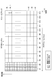
- FIG. 2 shows an example of a downlink subframe configuration.
- one subframe is 1 ms, for example, and 14 OFDM symbols exist in one subframe.
- the subframe may be called a transmission time interval (TTI: Transmission Time Interval).
- TTI Transmission Time Interval
- numbers in the time axis direction (# 1, # 2,..., # 14) indicate numbers for identifying OFDM symbols
- numbers in the frequency axis direction # 1, # 2,..., # L-1, #L; L is a positive integer
- L is a positive integer
- User data, a synchronization channel (SCH), a broadcast channel (BCH), and the like are mapped in an OFDM symbol to which the physical downlink control channel PDCCH is not mapped.
- the user data is, for example, an IP packet by web browsing, file transfer (FTP), voice packet (VoIP) or the like, a control signal for processing of radio resource control (RRC).
- FTP file transfer
- VoIP voice packet
- RRC radio resource control
- L resource blocks are prepared in the system band.
- the frequency band per resource block is, for example, 180 kHz, and there are, for example, 12 subcarriers in one resource block.
- the total number L of resource blocks may be 25 when the system bandwidth is 5 MHz, 50 when the system bandwidth is 10 MHz, 100 when the system bandwidth is 20 MHz, and the like. .
- system bandwidths of different sizes may be used depending on regions or cells.
- the user apparatus can perform mobile communication using a shared channel within the range of the system bandwidth in the region or cell.
- FIG. 4 shows an example of uplink subframe configuration in the LTE system.
- FIG. 4 shows resources (multiple resource blocks) for transmitting a physical uplink shared channel (PUSCH) and resources (uplink control) for users to whom such resources are not allocated to transmit uplink control signals.
- PUSCH physical uplink shared channel
- Dedicated band for signals The latter is called a physical uplink control signal (PUCCH: Physical Uplink Control CHannel).
- PUCCH Physical Uplink Control CHannel
- one or more of the four resource blocks are allocated to the user, the first and second hopping control signals are prepared in a certain subframe or transmission time interval (TTI), and the first subframe is transmitted in the subsequent subframe.
- Third and fourth hopping control signals are prepared. Each hopping control signal corresponds to PUCCH.
- Each of the first to fourth hopping control signals may be occupied by one user or multiplexed by a plurality of users.
- the size of the system bandwidth is prepared in the same level as the downlink. In the LTE system, a variable system bandwidth is prepared for uplink and downlink.
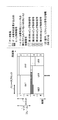
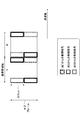
- FIG. 5 shows a state in which a control signal is transmitted in the downlink according to an embodiment of the present invention.
- an 80 MHz system bandwidth is prepared for the IMT-A system, and mobile communication is performed with a variable system bandwidth of 80 MHz or less.
- System bandwidth may vary from region to region or cell. It is not essential for all users to be able to communicate at 80 MHz, and there may be users who can communicate only with a bandwidth of 40 MHz, for example.
- the maximum system bandwidth prepared in the IMT-A system is referred to as an advanced system bandwidth (the bandwidth is the advanced system bandwidth).
- the advanced system band is divided into reference bandwidth areas, and the reference bandwidth is 20 MHz in the illustrated example. Although not required, this 20MHz corresponds to the maximum bandwidth in LTE systems.
- control signals are mapped to the first one to three OFDM symbols. Also in this embodiment, the control signal is mapped to the first one to three OFDM symbols. In the illustrated example, a control signal is mapped to three OFDM symbols.
- the first user UE1 (E-UTRA) has joined the LTE system but has not joined the IMT-A system. Assuming that each area is P, Q, R, S from the left for convenience, the control signal addressed to this user is mapped to the band of the second area Q from the left. As described above, the control signal includes uplink / downlink scheduling information, transmission power control information, and the like. As shown in the upper part of the figure, the LTE system control signal and the IMT-A system control signal are resource element units by frequency division multiplexing (FDM) and time and multiplexing (TDM). (However, the control channel in the IMT advanced system may be code-multiplexed.) One resource element represents a resource of a unit specified by one subcarrier and one OFDM symbol.
- FDM frequency division multiplexing
- TDM time and multiplexing
- control signal addressed to the user of the LTE system is mapped only in the second area from the left. Therefore, this user can extract the control signal addressed to the user apparatus by decoding only the second 20 MHz bandwidth from the left.
- the downlink control signal for the LTE system is channel-coded so as to be within a bandwidth of 20 MHz.
- the control signal only needs to be mapped so as to be within the 20 MHz area for the LTE system.
- the second user UE2 (IMT-A) is subscribed to the IMT-A system.
- the control signal addressed to this user is mapped to the entire advanced system band (mapped to all four areas).
- uplink / downlink scheduling information, transmission power control information, and the like may be included in the control information.
- each user shares a physical channel and performs mobile communication using one or more resource blocks in the system band.
- the third user UE3 (IMT-A) is also subscribed to the IMT-A system. However, the control signal addressed to this user is mapped to a part rather than the entire advanced system band (mapped to two areas-40 MHz).
- the control signal addressed to the third user UE2 (IMT-A) and the control signal addressed to the first and second users UE1,2 are channel-coded separately.
- the control signal addressed to the user of the LTE system is channel-encoded within the 20 MHz area permitted for the LTE system. Further, the control signals addressed to the first, second and third users are channel-coded separately. Therefore, the first user UE1 (E-UTRA) can appropriately decode the control signal addressed to the own device regardless of the presence or absence of the control signals of the second and third users (in other words, other control signals). You don't have to be aware of it.) Conversely, the second and third users UE2, 3 (IMT-A) can also appropriately decode the control signal addressed to the own device regardless of the presence or absence of the control signal of the first user. In this way, both the old and new users can appropriately take out the control signal addressed to their own device regardless of whether the control signal of the other system is present.
- control signal addressed to a user belonging to the IMT-A system is mapped in a transmission frame over a plurality of areas
- the control signal addressed to the user is (1) a channel for each area of the reference bandwidth (20 MHz). It may be encoded, or (2) it may be channel encoded all over a plurality of areas.
- FIG. 5 shows a state in which a control signal addressed to UE2 (IMT-A) is mapped over four areas P, Q, R, and S, and channel coding is performed for each area.
- a control signal addressed to UE3 (IMT-A) is mapped to areas R and S.
- a control signal addressed to UE1 (E-UTRA) belonging to the LTE system is mapped so as to be within one area.
- a control signal addressed to UE1 (E-UTRA) is mapped within 20 MHz of area Q. Therefore, it is preferable from the viewpoint of increasing the commonality or commonality with the LTE system that the control signal of the IMT-A system is also channel-coded and mapped for each area.
- UE2 can use appropriate resources in all four areas (80MHz).
- resource allocation information scheduling information
- the scheduling information for 20 MHz of area P is mapped to area P.
- scheduling information for each band of areas Q, R, and S is mapped to areas Q, R, and S, respectively. This simplifies the correspondence between the mapping position of the control signal and the shared channel resource. This correspondence can be used, for example, when specifying the resource position of the shared channel to be retransmitted.
- the lower right side of FIG. 5 shows a state where the control signal addressed to UE2 (IMT-A) is channel-coded for the entire four areas, not for each area.
- the entire two areas R and S are channel-coded in a lump.
- a control signal addressed to UE1 (E-UTRA) belonging to the LTE system is mapped so as to be within one area Q.
- the control signal it may not be preferable from the viewpoint of commonality that the unit of channel coding differs between the IMT-A system and the LTE system.
- the control signal of the IMT-A system it is preferable to lengthen one unit of channel coding from the viewpoint of increasing the error correction capability (encoding gain is improved).
- this method is preferable in that a frequency diversity effect can be expected.
- FIG. 6 shows an example of mapping control signals differently.
- the control signal of the IMT-A system is mapped to a plurality of areas P, Q, R, and S according to the available bandwidth of the user.
- the control signal does not have to be transmitted at 80 MHz.
- the control signal of one user is mapped to only one area regardless of the communication capability of each user's data signal (the usable bandwidth is wide or narrow). The correspondence between the user and the area is appropriately determined.
- the control signal addressed to the first user UE1 is mapped to the area Q. This is the same as in FIG.
- the control signal addressed to the second user UE2 is mapped to the area P.
- the control signal addressed to the third user UE3 is mapped to the area R.
- area S control signals addressed to other users not shown (users who have joined the IMT-A system) are mapped. Since the control signal addressed to any user is mapped only in one area, this example is preferable from the viewpoint of ensuring commonality.
- the reference bandwidth is 20 MHz, but another bandwidth may be used.
- the reference bandwidth may be 15 MHz.
- the reference bandwidth can be any value, but preferably matches any of the variable system bandwidths of the LTE system. Specifically, the reference bandwidth preferably matches any of 1.4 MHz, 3 MHz, 5 MHz, 10 MHz, 15 MHz, or 20 MHz.
- both ends of the advanced system band may not be aligned with the boundary of the division by the reference bandwidth.
- Fig. 7 shows the case where three 20MHz areas and four 15MHz areas are included in the 80MHz advanced system band for the IMT-A system. In either case, both ends of the advanced system band are not aligned with the reference bandwidth area. Again, any of the reference bandwidth areas are allocated to the LTE system. As described above, there may be various cases regarding the interrelationship between the areas of the advanced system band, the LTE system band, and the reference bandwidth.
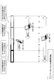
- FIG. 8 shows a state in which a control signal is transmitted in the uplink according to an embodiment of the present invention.
- a system bandwidth of 40 MHz is prepared for the uplink of the IMT-A system, and mobile communication is performed with a variable system bandwidth of 40 MHz or less.
- System bandwidth may vary from region to region or cell. It is not essential for all users to be able to communicate at 40 MHz. For example, there may be users who can communicate only with a bandwidth such as 20 MHz.
- the maximum system bandwidth prepared in the IMT-A system is referred to as an advanced system bandwidth (the bandwidth is the advanced system bandwidth).
- the advanced system band is divided into areas of the reference bandwidth, and the reference bandwidth is 20 MHz in the illustrated example. The two areas are designated V and W for convenience. Although not required, this 20MHz corresponds to the maximum bandwidth in LTE systems.
- the advanced system band is exemplified as 80 MHz, but in the uplink, 40 MHz is exemplified. These numerical values are merely examples, and any other appropriate numerical values may be used. Therefore, an advanced system band of 80 MHz may be prepared for the uplink. However, while the demand for high speed and large capacity is strongly demanded for the downlink, there are many situations in which the speed increase in the uplink is not so demanded. For this reason, in the illustrated example, only 40 MHz is prepared for the uplink.
- resources dedicated to the control signal are secured at both ends of the 20 MHz system band (see FIG. 4). Also in this embodiment, resources dedicated to control signals are prepared at both ends of the reference bandwidth of 20 MHz. This resource is prepared from the viewpoint of enabling an LTE system user to transmit an uplink control signal (PUCCH) regardless of the presence or absence of the IMT-A system. If signals of the LTE system are transmitted in the area V, resources for control signals (PUCCH) are secured at least at both ends in the area V. As described with reference to FIG. 4, the uplink signal in the LTE system is transmitted in a single carrier scheme. In order to obtain the signal quality improvement effect due to the frequency diversity effect while using the single carrier method, the uplink control signal is transmitted with frequency hopping between both ends of the reference bandwidth.
- the first user UE1 (E-UTRA) has joined the LTE system but has not joined the IMT-A system. Therefore, the uplink control signal (PUCCH) from the first user UE1 is transmitted while performing frequency hopping in the dedicated bands at both ends of the area V.
- PUCCH uplink control signal
- the second user UE2 (IMT-A) has joined the IMT-A system and can transmit with a bandwidth of 40 MHz.
- the user's uplink control signal is transmitted using resources prepared not only in the area V but also in the area W. In the area V, similarly to the area W, resources dedicated to control signals are secured at both ends of the area.
- the uplink control signal may include any appropriate information.
- the resource is not allocated to the uplink shared channel, but this resource may be used when reporting some information to the base station. For example, this resource may be used to periodically report CQI to the base station and / or to promptly report acknowledgment information (ACK / NACK) for downlink data signals.
- the uplink control signal of UE2 it is not essential for the uplink control signal of UE2 to use all resources prepared in areas V and W. For example, only the left side of the area V and the right side of the area W may be used. An appropriate amount of resources may be determined based on the amount of control information and / or the required frequency diversity effect.
- the uplink is a single carrier system, but in the illustrated IMT-A system, a multicarrier system is allowed for the uplink.
- the IMT-A system selectively uses the appropriate one of the single carrier scheme and the multicarrier scheme for the uplink (the multicarrier scheme is used in FIG. 8 and the single carrier scheme in FIG. Is used.)
- a single or multi-carrier scheme may be fixedly used for the uplink. Therefore, the uplink control signals may be transmitted simultaneously at different frequencies in the areas V and W.
- the third user UE3 (IMT-A) is also subscribed to the IMT-A system, but can transmit only with a bandwidth of 20 MHz in the uplink.
- the user's uplink control signal may be transmitted in the area V or W, but is transmitted using only the area W in the illustrated example.
- the uplink control signal may be simultaneously transmitted at different frequencies in the area W as illustrated.
- the control signals of the first, second, and third users are orthogonally multiplexed by an appropriate orthogonal multiplexing method.
- the first and second users are orthogonalized by the code multiplexing method.
- the first and third users are orthogonalized by frequency multiplexing.
- the second and third users are also orthogonalized by the code multiplexing method.
- the channel coding of the control signal may be performed for each area, or in the plurality of areas. It may be done in a lump. From the viewpoint of increasing commonality between the LTE system and the IMT-A system, it is preferable to perform channel coding for each area of the reference bandwidth. From the viewpoint of improving the coding gain and the frequency diversity effect, it is preferable to collectively perform channel coding of control signals over a plurality of areas.
- FIG. 9 shows a state in which all uplink control signals from each UE are transmitted by the single carrier method. This may be advantageous, for example, when the amount of control information transmitted on the uplink is small.
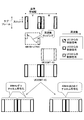
- FIG. 10 shows a partial functional block diagram of the base station apparatus.
- the scheduler 102, the control signal generation unit 104 and the data signal generation unit 110 for the LTE system, the control signal generation unit 106 and the data signal generation unit 112 for the ITM-A system, and the multiplexing units 108, 114, and 116 are related to the downlink. It is shown.
- the demultiplexing units 120, 122, 128, the control signal demodulation unit 124 and the data signal demodulation unit 130 for the LTE system, the control signal demodulation unit 126 and the data signal demodulation unit 132 for the IMT-A system are shown for the uplink. Yes.
- the scheduler 102 makes a radio resource allocation plan in the downlink and uplink (performs scheduling). Scheduling may be based on any suitable amount, and may be based on any suitable criteria and / or algorithm. As an example, scheduling may be performed on the downlink based on CQI reported from the user apparatus. For the uplink, scheduling may be performed based on the reception quality of the pilot signal received by the base station. Scheduling may be done, for example, according to a proportional fairness method. In this embodiment, scheduling is performed not only for the 20 MHz wide band for the LTE system but also for the 80 MHz wide band for the IMT-A system that includes the downlink. Also for the uplink, scheduling is performed not only for the 20 MHz wide band for the LTE system but also for the 40 MHz wide band for the IMT-A system including the band. Scheduling is performed taking into account adaptive modulation and channel coding schemes.
- the LTE system is operating in a specific reference bandwidth (20 MHz) area.
- the LTE system is operating in Area Q for the downlink and Area R for the uplink. Therefore, scheduling information regarding the bandwidth of the downlink area Q is provided to the control signal generation unit 104, and other scheduling information of the downlink is provided to the control signal generation unit 106. Similarly, scheduling information regarding the bandwidth of the uplink region R is provided to the control signal generation unit 104, and other scheduling information for the uplink is provided to the control signal generation unit 106.
- the LTE system control signal generation unit 104 generates an LTE system downlink control signal.
- the control signal generation unit 104 generates a downlink control signal by performing processing such as channel coding, data modulation, and interleaving.
- This downlink control signal is typically a PDCCH or L1 / L2 control channel.
- This downlink control signal is channel-coded for each user and mapped to a band in the area Q.
- This downlink control signal may be referred to as a low layer control signal.
- the downlink control signal typically includes scheduling information, but may include other control information such as transmission power control information.
- the LTE system data signal generator 110 generates a downlink data signal for the LTE system.
- the data signal generation unit 110 generates a downlink data signal by performing processing such as channel coding, data modulation, and interleaving.
- This downlink data signal is called PDSCH.
- the PDSCH may include user traffic data, broadcast information, high layer control information, and the like.
- the control signal generator 106 for the ITM-A system generates a downlink control signal for the ITM-A system.
- the control signal generation unit 106 generates a downlink control signal by performing processing such as channel coding, data modulation, and interleaving.
- This downlink control signal corresponds to the control signal of the second user UE2 described in FIG. 5, the control signal of the third user UE3, and the like.
- This downlink control signal also typically includes scheduling information, but may include other control information such as transmission power control information.
- this downlink control signal is channel-coded for each user and mapped to an area associated with each user.
- the data signal generator 112 for the IMT-A system generates a downlink data signal for the IMT-A system.
- the data signal generation unit 112 generates a downlink data signal by performing processing such as channel coding, data modulation, and interleaving.
- This downlink data signal may also include user traffic data, broadcast information, high layer control information, and the like.
- the multiplexing units 108, 114, and 116 orthogonally multiplex the signals input thereto using an appropriate method.
- the control signal for LTE system and the control signal for IMT-A system are multiplexed on a resource element basis using frequency division multiplexing (FDM) and time division multiplexing (TDM).
- the unit 108 performs orthogonal multiplexing.
- the data signal for the LET system and the data signal for the IMT-A system are orthogonally multiplexed by the multiplexing unit 114 in resource block units in the frequency division multiplexing (FDM) scheme.
- the control signal and the data signal are orthogonally multiplexed by the multiplexing unit 116 using a time division multiplexing (TDM) method.
- TDM time division multiplexing
- a code division multiplexing (CDM) method may be used together.
- the demultiplexing units 120, 122, and 128 demultiplex the multiplexed signal input thereto into signals before multiplexing.
- the separation unit 120 separates the control signal and the data signal received from each user by the TDM method.
- the separation unit 122 separates the signal into a control signal for the LTE system and a control signal for the IMT-A system using the FDM and TDM systems.
- the separation unit 128 separates the signal into a data signal for the LTE system and a data signal for the IMT-A system using the FDM method.
- the signal of the IMT-A system may be transmitted in a band wider than the basic bandwidth (20 MHz). Therefore, the demultiplexing units 128 and 122 take out the control signal in consideration of the transmission bandwidth of each user.
- the LTE system control signal demodulation unit 124 performs processing such as deinterleaving, demodulation, and decoding on the uplink control signal for the LTE system, and extracts control information from each user.
- the downlink data signal acknowledgment information (ACK / NACK) and / or CQI indicating the state of the downlink channel is notified to the scheduler 102 and is taken into account in the subsequent scheduling.
- the LTE system data signal demodulation unit 130 performs processing such as deinterleaving, demodulation, and decoding on the uplink data signal for the LTE system, and extracts traffic data from each user.
- the traffic data is subjected to error detection and error correction by a functional element (not shown), and when retransmission is required, this is notified to the scheduler 102.
- the IMT-A system control signal demodulator 126 performs processing such as deinterleaving, demodulation, and decoding on the uplink control signal for the IMT-A system, and extracts control information from each user.
- the downlink data signal acknowledgment information (ACK / NACK) and / or CQI indicating the state of the downlink channel is notified to the scheduler 102 and is taken into account in the subsequent scheduling.
- the IMT-A system data signal demodulator 132 performs processing such as deinterleaving, demodulation, and decoding on the uplink data signal for the IMT-A system, and extracts traffic data from each user.
- the traffic data is subjected to error detection and error correction by a functional element (not shown), and when retransmission is required, this is notified to the scheduler 102.
- FIG. 11 shows a partial functional block diagram of the user equipment. This user equipment is used in the IMT-A system. User equipments used in LTE systems have similar elements, but there are different configurations and / or processes due to different signal bands handled.
- FIG. 11 shows a separation unit 202, a downlink control signal demodulation unit 204, a downlink data signal demodulation unit 206, an uplink data signal generation unit 208, and an uplink control signal generation unit 210.
- the separation unit 202 separates the received signal into a control signal and a data signal. This separation is mainly performed using the TDM method.
- the downlink control signal demodulator 204 confirms whether or not the received downlink control signal includes a control signal addressed to itself, and if so, also confirms the content. As described above, the control signal typically includes scheduling information.
- the downlink data signal demodulator 206 receives the downlink data signal addressed to the own apparatus according to the scheduling information when it is transmitted.
- the uplink data signal generation unit 208 prepares an uplink data signal according to the scheduling information when transmission of the uplink data signal from the own device is permitted.
- the uplink control signal generation unit 210 prepares the uplink control signal so that the uplink control signal is transmitted by the method described with reference to FIGS. 8 and 9.
- the user device When the user device extracts the downlink control signal from the received signal, the user device checks whether or not the control signal addressed to the user device is included therein. In the case of a user apparatus of the LTE system, blind detection is attempted for a signal having a bandwidth of 20 MHz corresponding to the area Q in FIG. As an example, first, decoding of a control signal for one user is attempted using identification information (UE-ID) of the own device. The success or failure of decoding is determined by checking the CRC error detection result of the decoding result. If the decoding is successful, the control information is confirmed as information addressed to the own apparatus. If decoding of control signals for a predetermined number of users fails, the user apparatus waits for a signal of the next subframe. When there is a control signal addressed to the own apparatus, downlink and / or uplink communication is performed according to the control signal.
- UE-ID identification information
- each user tries blind detection according to the area where the control signal of the own device may be mapped. For example, in the case of the second user UE2 (IMT-A) in FIG. 5, blind detection is attempted for signals in all four areas P, Q, R, and S (all 80 MHz). In the case of the third user UE3 (IMT-A) in FIG. 5, blind detection is tried for signals in two areas R and S (40 MHz).
- decoding of a control signal for one user is attempted using identification information (UE-ID) of the own device. The success or failure of decoding is determined by checking the CRC error detection result of the decoding result.
- UE-ID identification information
- control information is confirmed as information addressed to the own apparatus. If decoding of control signals for a predetermined number of users fails, the user apparatus waits for a signal of the next subframe. When there is a control signal addressed to the own apparatus, downlink and / or uplink communication is performed according to the control signal.
- a user apparatus of the LTE system searches for a control signal addressed to itself, it does not need to know how the control signal of the IMT-A system is transmitted. Therefore, it seems to the user of the LTE system that only the LTE system exists in the area.
- the user apparatus of the IMT-A system does not need to know how the control signal of the LTE system is transmitted when searching for the control signal addressed to itself. Therefore, it seems to the user of the IMT-A system that only the IMT-A system exists in the area.
- the present invention is widely applicable when systems having different maximum system bandwidths coexist, and is not limited to the above embodiment.
- the present invention may be applied to any appropriate combination of an HSDPA / HSUPA W-CDMA system, an LTE system, an IMT-Advanced system, a WiMAX system, and a Wi-Fi system.
Abstract
Description
3GPP, TR25.912 (V7.1.0), "Feasibility study for Evolved UTRA and UTRAN", Sept. 2006 FIG. 1 schematically shows how 3G system, LTE system and IMT-A system coexist in the same area. When new and old systems with different radio access systems coexist, it is important to maintain backward compatibility. This is because maintaining backward compatibility is preferable not only for the user but also for the operator. When a new system is studied while maintaining backward compatibility, it is particularly important how the control signal is transmitted between the old and new systems. However, it seems that the examination of how to transmit the control signal with a newer system while maintaining backward compatibility with the LTE system or the like has not been sufficiently advanced so far.
3GPP, TR25.912 (V7.1.0), "Feasibility study for Evolved UTRA and UTRAN", Sept. 2006
前記第1システムの制御信号を生成する第1生成手段と、
前記第2システムの制御信号を生成する第2生成手段と、
前記第1及び第2生成手段各々からの制御信号を直交多重する多重手段と、
直交多重後の制御信号を含む下り信号を送信する送信手段と、
を有する。前記アドバンストシステム帯域は、基本帯域幅の区域を複数個含むように区分けされる。前記第1システムの制御信号は1つの区域内に含まれる。前記第2システムの制御信号は1つ以上の区域内に含まれる。 (DL-eNB) In one form of the present invention, a base station apparatus used in an area where at least the first and second systems coexist is used. In the first system, mobile communication is performed using a variable system bandwidth equal to or less than the basic bandwidth. In the second system, mobile communication is performed using a variable system bandwidth that is equal to or less than the bandwidth of the advanced system bandwidth that is wider than the basic bandwidth. The base station device
First generation means for generating a control signal of the first system;
Second generation means for generating a control signal of the second system;
Multiplexing means for orthogonally multiplexing control signals from each of the first and second generation means;
Transmitting means for transmitting a downlink signal including a control signal after orthogonal multiplexing;
Have The advanced system band is divided to include a plurality of basic bandwidth areas. The control signal of the first system is included in one area. The control signal of the second system is included in one or more areas.
受信信号中の制御信号を他の信号から分離する分離手段と、
前記制御信号から自装置宛ての制御情報を取り出す取得手段と、
自装置宛の制御情報に従って、ユーザトラフィックデータを含むデータ信号を受信又は送信する手段と、
を有する。前記アドバンストシステム帯域は、基本帯域幅の区域を複数個含むように区分けされる。前記第1システムの制御信号は1つの区域内に含まれる。前記第2システムの制御信号は1つ以上の区域内に含まれている。 (DL-UE) In one form of this invention, the user apparatus of the said 2nd system used in the area where the 1st and 2nd system coexists at least is used. The user device is
Separating means for separating the control signal in the received signal from other signals;
Obtaining means for extracting control information addressed to the device from the control signal;
Means for receiving or transmitting a data signal including user traffic data according to the control information addressed to the device;
Have The advanced system band is divided to include a plurality of basic bandwidth areas. The control signal of the first system is included in one area. The control signal of the second system is included in one or more areas.
受信信号から前記第1システムの制御信号を取り出す第1取得手段と、
受信信号から前記第2システムの制御信号を取り出す第2取得手段と、
前記第1及び第2取得手段各々からの制御信号に応じて、無線リソースの割り当てを計画するスケジューリング手段と、
を有する。前記アドバンストシステム帯域は、基本帯域幅の区域を複数個含むように区分けされる。前記第1システムの制御信号は1つの区域内に含まれる。前記第2システムの制御信号は1つ以上の区域内に含まれる。 (UL-eNB) In one form of this invention, the base station apparatus used in the area where the 1st and 2nd system coexists at least is used. The base station device
First acquisition means for extracting a control signal of the first system from a received signal;
Second acquisition means for extracting a control signal of the second system from a received signal;
Scheduling means for planning radio resource allocation in response to control signals from each of the first and second acquisition means;
Have The advanced system band is divided to include a plurality of basic bandwidth areas. The control signal of the first system is included in one area. The control signal of the second system is included in one or more areas.
前記第2システムの制御信号を生成する生成手段と、
前記制御信号を送信する送信手段と、
を有する。前記アドバンストシステム帯域は、基本帯域幅の区域を複数個含むように区分けされる。前記第1システムの制御信号は1つの区域内に含まれる。前記第2システムの制御信号は、1つ以上の区域内に含まれ且つ区域の境界に隣接する制御信号専用の帯域に含まれる。 (UL-UE) According to one form of this invention, the user apparatus of the said 2nd system used in the area where the 1st and 2nd system coexists at least is used. The user device is
Generating means for generating a control signal of the second system;
Transmitting means for transmitting the control signal;
Have The advanced system band is divided to include a plurality of basic bandwidth areas. The control signal of the first system is included in one area. The control signal of the second system is included in a band dedicated to control signals included in one or more areas and adjacent to the boundaries of the areas.
104 LTEシステム用の制御信号生成部
110 LTEシステム用のデータ信号生成部
106 ITM-Aシステム用の制御信号生成部
112 IMT-Aシステム用のデータ信号生成部
108,114,116 多重部
120,122,128 分離部
124 LTEシステム用の制御信号復調部
126 IMT-Aシステム用の制御信号復調部
130 LTEシステム用のデータ信号復調部
132 IMT-Aシステム用のデータ信号復調部
202 分離部
204 下り制御信号復調部
206 下りデータ信号復調部
208 上りデータ信号生成部
210 上り制御信号生成部 102
2.下りリンク
2.1 チャネル符号化の単位
2.2 マッピング位置
3.上りリンク
4.基地局装置
5.ユーザ装置 1.
LTEでは、上下リンクともに1つ以上の物理チャネルを複数の移動局(ユーザ装置)で共有して移動通信が行われる。下りリンクでは、直交周波数分割多重接続(OFDMA)方式が使用される。上りリンクでは、シングルキャリアの周波数分割多重接続(SC-FDMA)方式が使用される。SC-FDMA方式は、DFTスプレッド(Discrete Fourier Transformation spread)OFDM方式とも呼ばれる。複数の移動局で共有されるチャネルは、一般に共有チャネルと呼ばれ、上りリンクにおいては上り物理共有チャネル(PUSCH:Physical Uplink Shared Channel)、下りリンクにおいては下り物理共有チャネル(PDSCH:Physical Downlink Shared Channel)と呼ばれる。 <1. LTE system>
In LTE, one or more physical channels are shared by a plurality of mobile stations (user apparatuses) for both uplink and downlink. In the downlink, an orthogonal frequency division multiple access (OFDMA) scheme is used. In the uplink, a single carrier frequency division multiple access (SC-FDMA) scheme is used. The SC-FDMA scheme is also called a DFT spread (Discrete Fourier Transformation spread) OFDM scheme. A channel shared by a plurality of mobile stations is generally called a shared channel.In the uplink, an uplink physical shared channel (PUSCH: Physical Uplink Shared Channel), and in the downlink, a downlink physical shared channel (PDSCH: Physical Downlink Shared Channel). ).
図5は本発明の一実施例により下りリンクで制御信号が伝送される様子を示す。図示の例では、IMT-Aシステムに80MHzのシステム帯域幅が用意され、80MHz以下の可変のシステム帯域幅で移動通信が行われる。システム帯域幅は地域により又はセルにより異なってよい。全てのユーザが80MHzで通信できることは必須でなく、例えば40MHzのような帯域幅でしか通信できないユーザが存在するかもしれない。説明の便宜上、IMT-Aシステムで用意されている最大のシステム帯域を、アドバンストシステム帯域と呼ぶことにする(その帯域幅は、アドバンストシステム帯域幅である。)。アドバンストシステム帯域は、基準帯域幅の区域に区分けされ、図示の例で基準帯域幅は20MHzである。必須ではないが、この20MHzはLTEシステムでの最大帯域幅に対応している。 <2. Downlink>
FIG. 5 shows a state in which a control signal is transmitted in the downlink according to an embodiment of the present invention. In the illustrated example, an 80 MHz system bandwidth is prepared for the IMT-A system, and mobile communication is performed with a variable system bandwidth of 80 MHz or less. System bandwidth may vary from region to region or cell. It is not essential for all users to be able to communicate at 80 MHz, and there may be users who can communicate only with a bandwidth of 40 MHz, for example. For convenience of explanation, the maximum system bandwidth prepared in the IMT-A system is referred to as an advanced system bandwidth (the bandwidth is the advanced system bandwidth). The advanced system band is divided into reference bandwidth areas, and the reference bandwidth is 20 MHz in the illustrated example. Although not required, this 20MHz corresponds to the maximum bandwidth in LTE systems.
IMT-Aシステムに属する或るユーザ宛の制御信号が複数の区域にわたって、伝送フレーム内にマッピングされる際、そのユーザ宛の制御信号は、(1)基準帯域幅(20MHz)の区域毎にチャネル符号化されてもよいし、(2)複数の区域全体で一括してチャネル符号化されてもよい。 <2.1 Channel coding unit>
When a control signal addressed to a user belonging to the IMT-A system is mapped in a transmission frame over a plurality of areas, the control signal addressed to the user is (1) a channel for each area of the reference bandwidth (20 MHz). It may be encoded, or (2) it may be channel encoded all over a plurality of areas.
図6は制御信号を別様にマッピングする例を示す。図5の例では、IMT-Aシステムの制御信号は、ユーザの使用可能な帯域幅に応じて複数の区域P,Q,R,Sにマッピングされていた。しかしながら、例えば、データ信号が80MHzで通信される際、制御信号も80MHzで伝送しなければならないわけではない。図6に示される例では、各ユーザのデータ信号の通信能力(使用可能な帯域幅の広狭)によらず、1ユーザの制御信号は1つの区域にしかマッピングされない。ユーザと区域との対応関係は、適宜決定される。図示の例では、第1ユーザUE1宛の制御信号は区域Qにマッピングされている。この点は、図5の場合と同じである。第2ユーザUE2宛の制御信号は区域Pにマッピングされている。第3ユーザUE3宛の制御信号は区域Rにマッピングされている。区域Sには不図示の他のユーザ(IMT-Aシステムに加入しているユーザ)宛の制御信号がマッピングされる。どのユーザ宛の制御信号も1つの区域内にしかマッピングされないので、この例はコモナリティを確保する等の観点から好ましい。 <2.2 Mapping position>
FIG. 6 shows an example of mapping control signals differently. In the example of FIG. 5, the control signal of the IMT-A system is mapped to a plurality of areas P, Q, R, and S according to the available bandwidth of the user. However, for example, when a data signal is communicated at 80 MHz, the control signal does not have to be transmitted at 80 MHz. In the example shown in FIG. 6, the control signal of one user is mapped to only one area regardless of the communication capability of each user's data signal (the usable bandwidth is wide or narrow). The correspondence between the user and the area is appropriately determined. In the illustrated example, the control signal addressed to the first user UE1 is mapped to the area Q. This is the same as in FIG. The control signal addressed to the second user UE2 is mapped to the area P. The control signal addressed to the third user UE3 is mapped to the area R. In area S, control signals addressed to other users not shown (users who have joined the IMT-A system) are mapped. Since the control signal addressed to any user is mapped only in one area, this example is preferable from the viewpoint of ensuring commonality.
上記の例では、基準帯域幅は20MHzであったが、別の帯域幅が使用されてもよい。例えば、基準帯域幅は15MHzでもよい。基準帯域幅は、如何なる値でもよいが、LTEシステムの可変なシステム帯域幅の何れかに合っていることが好ましい。具体的には、基準帯域幅は、1.4MHz,3MHz,5MHz,10MHz,15MHz又は20MHzの何れかに合っていることが好ましい。また、アドバンストシステム帯域の両端が、基準帯域幅による区分けの境界に揃ってなくてもよい。 <Modification>
In the above example, the reference bandwidth is 20 MHz, but another bandwidth may be used. For example, the reference bandwidth may be 15 MHz. The reference bandwidth can be any value, but preferably matches any of the variable system bandwidths of the LTE system. Specifically, the reference bandwidth preferably matches any of 1.4 MHz, 3 MHz, 5 MHz, 10 MHz, 15 MHz, or 20 MHz. In addition, both ends of the advanced system band may not be aligned with the boundary of the division by the reference bandwidth.
図8は本発明の一実施例により上りリンクで制御信号が伝送される様子を示す。図示の例では、IMT-Aシステムの上りリンクに40MHzのシステム帯域幅が用意され、40MHz以下の可変のシステム帯域幅で移動通信が行われる。システム帯域幅は地域により又はセルにより異なってよい。全てのユーザが40MHzで通信できることは必須でなく、例えば20MHzのような帯域幅でしか通信できないユーザが存在するかもしれない。上りリンクについても、説明の便宜上、IMT-Aシステムで用意されている最大のシステム帯域を、アドバンストシステム帯域と呼ぶことにする(その帯域幅は、アドバンストシステム帯域幅である。)。アドバンストシステム帯域は、基準帯域幅の区域に区分けされ、図示の例では基準帯域幅は20MHzである。2つの区域は便宜上、V,Wで指定される。必須ではないが、この20MHzはLTEシステムでの最大帯域幅に対応している。 <3. Uplink>
FIG. 8 shows a state in which a control signal is transmitted in the uplink according to an embodiment of the present invention. In the illustrated example, a system bandwidth of 40 MHz is prepared for the uplink of the IMT-A system, and mobile communication is performed with a variable system bandwidth of 40 MHz or less. System bandwidth may vary from region to region or cell. It is not essential for all users to be able to communicate at 40 MHz. For example, there may be users who can communicate only with a bandwidth such as 20 MHz. Also for the uplink, for convenience of explanation, the maximum system bandwidth prepared in the IMT-A system is referred to as an advanced system bandwidth (the bandwidth is the advanced system bandwidth). The advanced system band is divided into areas of the reference bandwidth, and the reference bandwidth is 20 MHz in the illustrated example. The two areas are designated V and W for convenience. Although not required, this 20MHz corresponds to the maximum bandwidth in LTE systems.
図10は基地局装置の部分的な機能ブロック図を示す。図10にはスケジューラ102、LTEシステム用の制御信号生成部104及びデータ信号生成部110、ITM-Aシステム用の制御信号生成部106及びデータ信号生成部112、並びに多重部108,114,116が、下りリンクに関して示されている。図10には、分離部120,122,128、LTEシステム用の制御信号復調部124及びデータ信号復調部130、IMT-Aシステム用の制御信号復調部126及びデータ信号復調部132が、上りリンクに関して示されている。 <4. Base station equipment>
FIG. 10 shows a partial functional block diagram of the base station apparatus. In FIG. 10, the
図11はユーザ装置の部分的な機能ブロック図を示す。このユーザ装置は、IMT-Aシステムで使用される。LTEシステムで使用されるユーザ装置も同様な要素を有するが、取り扱う信号の帯域が異なることに起因して、異なる構成及び/又は処理が存在する。図11には、分離部202、下り制御信号復調部204、下りデータ信号復調部206、上りデータ信号生成部208及び上り制御信号生成部210が示されている。 <5. User device>
FIG. 11 shows a partial functional block diagram of the user equipment. This user equipment is used in the IMT-A system. User equipments used in LTE systems have similar elements, but there are different configurations and / or processes due to different signal bands handled. FIG. 11 shows a
Claims (20)
- 少なくとも第1及び第2システムが並存する地域で使用される基地局装置であって、
前記第1システムでは、基本帯域幅以下の可変のシステム帯域幅を用いて移動通信が行われ、
前記第2システムでは、前記基本帯域幅複数個分以上広いアドバンストシステム帯域の帯域幅以下の可変のシステム帯域幅を用いて移動通信が行われ、当該基地局装置は、
前記第1システムの制御信号を生成する第1生成手段と、
前記第2システムの制御信号を生成する第2生成手段と、
前記第1及び第2生成手段各々からの制御信号を直交多重する多重手段と、
直交多重後の制御信号を含む下り信号を送信する送信手段と、
を有し、前記アドバンストシステム帯域は、基本帯域幅の区域を複数個含むように区分けされ、
前記第1システムの制御信号は1つの区域内に含まれ、
前記第2システムの制御信号は1つ以上の区域内に含まれるようにした基地局装置。 A base station device used in an area where at least the first and second systems coexist,
In the first system, mobile communication is performed using a variable system bandwidth equal to or less than the basic bandwidth,
In the second system, mobile communication is performed using a variable system bandwidth that is equal to or less than the bandwidth of the advanced system bandwidth that is wider than the plurality of basic bandwidths, and the base station device
First generation means for generating a control signal of the first system;
Second generation means for generating a control signal of the second system;
Multiplexing means for orthogonally multiplexing control signals from each of the first and second generation means;
Transmitting means for transmitting a downlink signal including a control signal after orthogonal multiplexing;
And the advanced system band is divided to include a plurality of basic bandwidth areas,
The control signal of the first system is included in one area,
The base station apparatus in which the control signal of the second system is included in one or more areas. - 前記第2システムの制御信号が、複数の区域に含まれ且つ区域毎にチャネル符号化されている請求項1記載の基地局装置。 The base station apparatus according to claim 1, wherein the control signal of the second system is included in a plurality of areas and channel-coded for each area.
- 前記第2システムの制御信号が複数の区域に含まれ、該制御信号のチャネル符号化単位は、複数の区域全体である請求項1記載の基地局装置。 The base station apparatus according to claim 1, wherein the control signal of the second system is included in a plurality of areas, and a channel coding unit of the control signal is the entire plurality of areas.
- 前記第2システムの制御信号が、1つの区域内に含まれるようにした請求項1記載の基地局装置。 The base station apparatus according to claim 1, wherein the control signal of the second system is included in one area.
- 前記第2システムの制御信号が含まれる区域は、ユーザ毎に設定される請求項4記載の基地局装置。 The base station apparatus according to claim 4, wherein the area including the control signal of the second system is set for each user.
- 前記直交多重後の制御信号と、ユーザトラフィックデータを含むデータ信号とが、少なくとも時間分割多重方式で直交多重される請求項1記載の基地局装置。 The base station apparatus according to claim 1, wherein the control signal after orthogonal multiplexing and a data signal including user traffic data are orthogonally multiplexed at least by a time division multiplexing method.
- 少なくとも第1及び第2システムが並存する地域で使用される方法であって、
前記第1システムでは、基本帯域幅以下の可変のシステム帯域幅を用いて移動通信が行われ、
前記第2システムでは、前記基本帯域幅複数個分以上広いアドバンストシステム帯域の帯域幅以下の可変のシステム帯域幅を用いて移動通信が行われ、当該方法は、
前記第1システムの制御信号を生成する第1生成ステップと、
前記第2システムの制御信号を生成する第2生成ステップと、
前記第1及び第2生成手段各々からの制御信号を直交多重する多重ステップと、
直交多重後の制御信号を含む下り信号を送信する送信ステップと、
を有し、前記アドバンストシステム帯域は、基本帯域幅の区域を複数個含むように区分けされ、
前記第1システムの制御信号は1つの区域内に含まれ、
前記第2システムの制御信号は1つ以上の区域内に含まれるようにした方法。 A method used in an area where at least the first and second systems coexist,
In the first system, mobile communication is performed using a variable system bandwidth equal to or less than the basic bandwidth,
In the second system, mobile communication is performed using a variable system bandwidth that is equal to or less than the bandwidth of the advanced system bandwidth that is wider than a plurality of the basic bandwidths, and the method includes:
A first generation step of generating a control signal of the first system;
A second generation step of generating a control signal for the second system;
A multiplexing step of orthogonally multiplexing the control signals from each of the first and second generation means;
A transmission step of transmitting a downlink signal including a control signal after orthogonal multiplexing;
And the advanced system band is divided to include a plurality of basic bandwidth areas,
The control signal of the first system is included in one area,
The control signal of the second system is included in one or more areas. - 少なくとも第1及び第2システムが並存する地域で使用される前記第2システムのユーザ装置であって、
前記第1システムでは、基本帯域幅以下の可変のシステム帯域幅を用いて移動通信が行われ、
前記第2システムでは、前記基本帯域幅複数個分以上広いアドバンストシステム帯域の帯域幅以下の可変のシステム帯域幅を用いて移動通信が行われ、当該ユーザ装置は、
受信信号中の制御信号を他の信号から分離する分離手段と、
前記制御信号から自装置宛ての制御情報を取り出す取得手段と、
自装置宛の制御情報に従って、ユーザトラフィックデータを含むデータ信号を受信又は送信する手段と、
を有し、前記アドバンストシステム帯域は、基本帯域幅の区域を複数個含むように区分けされ、
前記第1システムの制御信号は1つの区域内に含まれ、
前記第2システムの制御信号は1つ以上の区域内に含まれているユーザ装置。 A user device of the second system used in an area where at least the first and second systems coexist,
In the first system, mobile communication is performed using a variable system bandwidth equal to or less than the basic bandwidth,
In the second system, mobile communication is performed using a variable system bandwidth that is equal to or less than the bandwidth of the advanced system bandwidth that is wider than the plurality of basic bandwidths.
Separating means for separating the control signal in the received signal from other signals;
Obtaining means for extracting control information addressed to the device from the control signal;
Means for receiving or transmitting a data signal including user traffic data according to the control information addressed to the device;
And the advanced system band is divided to include a plurality of basic bandwidth areas,
The control signal of the first system is included in one area,
User equipment wherein the control signal of the second system is included in one or more areas. - 前記第2システムの制御信号は、複数の区域に含まれ且つ区域毎にチャネル復号化される請求項8記載のユーザ装置。 The user apparatus according to claim 8, wherein the control signal of the second system is included in a plurality of areas and channel-decoded for each area.
- 前記第2システムの制御信号は、複数の区域に含まれ、該制御信号のチャネル復号化単位は、複数の区域全体である請求項8記載のユーザ装置。 The user apparatus according to claim 8, wherein the control signal of the second system is included in a plurality of areas, and a channel decoding unit of the control signal is the entire plurality of areas.
- 前記第2システムの制御信号が、1つの区域内に含まれている請求項8記載のユーザ装置。 The user apparatus according to claim 8, wherein the control signal of the second system is included in one area.
- 少なくとも第1及び第2システムが並存する地域で使用される前記第2システムのユーザ装置で使用される方法であって、
前記第1システムでは、基本帯域幅以下の可変のシステム帯域幅を用いて移動通信が行われ、
前記第2システムでは、前記基本帯域幅複数個分以上広いアドバンストシステム帯域の帯域幅以下の可変のシステム帯域幅を用いて移動通信が行われ、当該方法は、
受信信号中の制御信号を他の信号から分離する分離ステップと、
前記制御信号から自装置宛ての制御情報を取り出す取得ステップと、
自装置宛の制御情報に従って、ユーザトラフィックデータを含むデータ信号を受信又は送信するステップと、
を有し、前記アドバンストシステム帯域は、基本帯域幅の区域を複数個含むように区分けされ、
前記第1システムの制御信号は1つの区域内に含まれ、
前記第2システムの制御信号は1つ以上の区域内に含まれている方法。 A method used in a user device of the second system used in an area where at least the first and second systems coexist,
In the first system, mobile communication is performed using a variable system bandwidth equal to or less than the basic bandwidth,
In the second system, mobile communication is performed using a variable system bandwidth that is equal to or less than the bandwidth of the advanced system bandwidth that is wider than a plurality of the basic bandwidths, and the method includes:
A separation step of separating the control signal in the received signal from other signals;
Obtaining the control information addressed to the device from the control signal;
Receiving or transmitting a data signal including user traffic data according to control information addressed to the device;
And the advanced system band is divided to include a plurality of basic bandwidth areas,
The control signal of the first system is included in one area,
The control signal of the second system is included in one or more areas. - 少なくとも第1及び第2システムが並存する地域で使用される基地局装置であって、
前記第1システムでは、基本帯域幅以下の可変のシステム帯域幅を用いて移動通信が行われ、
前記第2システムでは、前記基本帯域幅複数個分以上広いアドバンストシステム帯域の帯域幅以下の可変のシステム帯域幅を用いて移動通信が行われ、当該基地局装置は、
受信信号から前記第1システムの制御信号を取り出す第1取得手段と、
受信信号から前記第2システムの制御信号を取り出す第2取得手段と、
前記第1及び第2取得手段各々からの制御信号に応じて、無線リソースの割り当てを計画するスケジューリング手段と、
を有し、前記アドバンストシステム帯域は、基本帯域幅の区域を複数個含むように区分けされ、
前記第1システムの制御信号は1つの区域内に含まれ、
前記第2システムの制御信号は1つ以上の区域内に含まれるようにした基地局装置。 A base station device used in an area where at least the first and second systems coexist,
In the first system, mobile communication is performed using a variable system bandwidth equal to or less than the basic bandwidth,
In the second system, mobile communication is performed using a variable system bandwidth that is equal to or less than the bandwidth of the advanced system bandwidth that is wider than the plurality of basic bandwidths, and the base station device
First acquisition means for extracting a control signal of the first system from a received signal;
Second acquisition means for extracting a control signal of the second system from a received signal;
Scheduling means for planning radio resource allocation in response to control signals from each of the first and second acquisition means;
And the advanced system band is divided to include a plurality of basic bandwidth areas,
The control signal of the first system is included in one area,
The base station apparatus in which the control signal of the second system is included in one or more areas. - 前記第2システムの制御信号は、複数の区域に含まれ且つ区域毎にチャネル復号化される請求項13記載の基地局装置。 The base station apparatus according to claim 13, wherein the control signal of the second system is included in a plurality of areas and is channel-decoded for each area.
- 前記第2システムの制御信号は、複数の区域に含まれ、該制御信号のチャネル復号化単位は、複数の区域全体である請求項13記載の基地局装置。 The base station apparatus according to claim 13, wherein the control signal of the second system is included in a plurality of areas, and a channel decoding unit of the control signal is the entire plurality of areas.
- 少なくとも第1及び第2システムが並存する地域で使用される方法であって、
前記第1システムでは、基本帯域幅以下の可変のシステム帯域幅を用いて移動通信が行われ、
前記第2システムでは、前記基本帯域幅複数個分以上広いアドバンストシステム帯域の帯域幅以下の可変のシステム帯域幅を用いて移動通信が行われ、当該方法は、
受信信号から前記第1システムの制御信号を取り出す第1取得ステップと、
受信信号から前記第2システムの制御信号を取り出す第2取得ステップと、
前記第1及び第2取得ステップ各々からの制御信号に応じて、無線リソースの割り当てを計画するスケジューリングステップと、
を有し、前記アドバンストシステム帯域は、基本帯域幅の区域を複数個含むように区分けされ、
前記第1システムの制御信号は1つの区域内に含まれ、
前記第2システムの制御信号は1つ以上の区域内に含まれるようにした方法。 A method used in an area where at least the first and second systems coexist,
In the first system, mobile communication is performed using a variable system bandwidth equal to or less than the basic bandwidth,
In the second system, mobile communication is performed using a variable system bandwidth that is equal to or less than the bandwidth of the advanced system bandwidth that is wider than a plurality of the basic bandwidths, and the method includes:
A first acquisition step of extracting a control signal of the first system from a received signal;
A second acquisition step of extracting a control signal of the second system from the received signal;
A scheduling step of planning radio resource allocation in response to control signals from each of the first and second acquisition steps;
And the advanced system band is divided to include a plurality of basic bandwidth areas,
The control signal of the first system is included in one area,
The control signal of the second system is included in one or more areas. - 少なくとも第1及び第2システムが並存する地域で使用される前記第2システムのユーザ装置であって、
前記第1システムでは、基本帯域幅以下の可変のシステム帯域幅を用いて移動通信が行われ、
前記第2システムでは、前記基本帯域幅複数個分以上広いアドバンストシステム帯域の帯域幅以下の可変のシステム帯域幅を用いて移動通信が行われ、当該ユーザ装置は、
前記第2システムの制御信号を生成する生成手段と、
前記制御信号を送信する送信手段と、
を有し、前記アドバンストシステム帯域は、基本帯域幅の区域を複数個含むように区分けされ、
前記第1システムの制御信号は1つの区域内に含まれ、
前記第2システムの制御信号は、1つ以上の区域内に含まれ且つ区域の境界に隣接する制御信号専用の帯域に含まれるようにしたユーザ装置。 A user device of the second system used in an area where at least the first and second systems coexist,
In the first system, mobile communication is performed using a variable system bandwidth equal to or less than the basic bandwidth,
In the second system, mobile communication is performed using a variable system bandwidth that is equal to or less than the bandwidth of the advanced system bandwidth that is wider than the plurality of basic bandwidths.
Generating means for generating a control signal of the second system;
Transmitting means for transmitting the control signal;
And the advanced system band is divided to include a plurality of basic bandwidth areas,
The control signal of the first system is included in one area,
The control signal of the second system is included in one or more areas and is included in a band dedicated to control signals adjacent to an area boundary. - 前記第2システムの制御信号が、複数の区域に含まれ且つ区域毎にチャネル符号化されている請求項17記載のユーザ装置。 The user apparatus according to claim 17, wherein the control signal of the second system is included in a plurality of areas and channel-coded for each area.
- 前記第2システムの制御信号が複数の区域に含まれ、該制御信号のチャネル符号化単位は、複数の区域全体である請求項17記載のユーザ装置。 The user apparatus according to claim 17, wherein the control signal of the second system is included in a plurality of areas, and a channel coding unit of the control signal is the entire plurality of areas.
- 少なくとも第1及び第2システムが並存する地域で使用される前記第2システムのユーザ装置で使用される方法であって、
前記第1システムでは、基本帯域幅以下の可変のシステム帯域幅を用いて移動通信が行われ、
前記第2システムでは、前記基本帯域幅複数個分以上広いアドバンストシステム帯域の帯域幅以下の可変のシステム帯域幅を用いて移動通信が行われ、当該方法は、
前記第2システムの制御信号を生成する生成ステップと、
前記制御信号を送信する送信ステップと、
を有し、前記アドバンストシステム帯域は、基本帯域幅の区域を複数個含むように区分けされ、
前記第1システムの制御信号は1つの区域内に含まれ、
前記第2システムの制御信号は、1つ以上の区域内に含まれ且つ区域の境界に隣接する制御信号専用の帯域に含まれるようにした方法。 A method used in a user device of the second system used in an area where at least the first and second systems coexist,
In the first system, mobile communication is performed using a variable system bandwidth equal to or less than the basic bandwidth,
In the second system, mobile communication is performed using a variable system bandwidth that is equal to or less than the bandwidth of the advanced system bandwidth that is wider than a plurality of the basic bandwidths, and the method includes:
Generating a control signal for the second system;
A transmission step of transmitting the control signal;
And the advanced system band is divided to include a plurality of basic bandwidth areas,
The control signal of the first system is included in one area,
The control signal of the second system is included in a band dedicated to control signals included in one or more areas and adjacent to an area boundary.
Priority Applications (6)
| Application Number | Priority Date | Filing Date | Title |
|---|---|---|---|
| EP09725200.1A EP2271150B1 (en) | 2008-03-28 | 2009-03-17 | Base station device, user device, and method used in mobile communication system |
| RU2010142259/07A RU2498530C2 (en) | 2008-03-28 | 2009-03-17 | Base station, user terminal and mobile communication method used in mobile communication system |
| CN2009801191412A CN102047713B (en) | 2008-03-28 | 2009-03-17 | Base station device, user device, and method used in mobile communication system |
| BRPI0910424A BRPI0910424A2 (en) | 2008-03-28 | 2009-03-17 | base station handset, user handset and method used in the mobile communication system |
| US12/935,041 US8553632B2 (en) | 2008-03-28 | 2009-03-17 | Base station apparatus, user apparatus, and method used in mobile communication system |
| ES09725200.1T ES2672015T3 (en) | 2008-03-28 | 2009-03-17 | Base station apparatus, user apparatus and method used in mobile communication systems |
Applications Claiming Priority (2)
| Application Number | Priority Date | Filing Date | Title |
|---|---|---|---|
| JP2008-088103 | 2008-03-28 | ||
| JP2008088103A JP5224869B2 (en) | 2008-03-28 | 2008-03-28 | Base station apparatus, user apparatus and method used in mobile communication system |
Publications (1)
| Publication Number | Publication Date |
|---|---|
| WO2009119385A1 true WO2009119385A1 (en) | 2009-10-01 |
Family
ID=41113582
Family Applications (1)
| Application Number | Title | Priority Date | Filing Date |
|---|---|---|---|
| PCT/JP2009/055180 WO2009119385A1 (en) | 2008-03-28 | 2009-03-17 | Base station device, user device, and method used in mobile communication system |
Country Status (9)
| Country | Link |
|---|---|
| US (1) | US8553632B2 (en) |
| EP (2) | EP3249975A1 (en) |
| JP (1) | JP5224869B2 (en) |
| KR (1) | KR20110007145A (en) |
| CN (1) | CN102047713B (en) |
| BR (1) | BRPI0910424A2 (en) |
| ES (1) | ES2672015T3 (en) |
| RU (1) | RU2498530C2 (en) |
| WO (1) | WO2009119385A1 (en) |
Cited By (2)
| Publication number | Priority date | Publication date | Assignee | Title |
|---|---|---|---|---|
| WO2010016274A1 (en) * | 2008-08-08 | 2010-02-11 | パナソニック株式会社 | Wireless communication base station device, wireless communication terminal device, and channel allocation method |
| CN102123444A (en) * | 2010-12-31 | 2011-07-13 | 华为技术有限公司 | Method, equipment and system for sharing transmission bandwidth among different systems |
Families Citing this family (12)
| Publication number | Priority date | Publication date | Assignee | Title |
|---|---|---|---|---|
| US9326253B2 (en) | 2007-11-15 | 2016-04-26 | Qualcomm Incorporated | Wireless communication channel blanking |
| US9009573B2 (en) | 2008-02-01 | 2015-04-14 | Qualcomm Incorporated | Method and apparatus for facilitating concatenated codes for beacon channels |
| JP2009231976A (en) * | 2008-03-19 | 2009-10-08 | Nec Corp | Method for handover between different radio access schemes, and wireless communication system |
| US9107239B2 (en) | 2008-04-07 | 2015-08-11 | Qualcomm Incorporated | Systems and methods to define control channels using reserved resource blocks |
| US8971260B2 (en) | 2008-08-04 | 2015-03-03 | Panasonic Intellectual Property Corporation Of America | Base station, terminal, band allocation method, and downlink data communication method |
| US8325661B2 (en) | 2008-08-28 | 2012-12-04 | Qualcomm Incorporated | Supporting multiple access technologies in a wireless environment |
| KR20110038994A (en) * | 2009-10-09 | 2011-04-15 | 삼성전자주식회사 | Method of receiving and transmitting multi-user control channels in wireless communication system with multiple antennas and apparatus thereof |
| US8396150B2 (en) | 2009-12-22 | 2013-03-12 | Intel Corporation | Tone count selection |
| US9467261B2 (en) * | 2013-09-25 | 2016-10-11 | Samsung Electronics Co., Ltd. | System and method for resource mapping for coverage enhancements of broadcast channels |
| US10200137B2 (en) * | 2013-12-27 | 2019-02-05 | Huawei Technologies Co., Ltd. | System and method for adaptive TTI coexistence with LTE |
| US9716579B2 (en) * | 2014-08-19 | 2017-07-25 | Intel IP Corporation | Subcarrier allocations for operation in mixed bandwidth environments |
| WO2017034329A1 (en) * | 2015-08-25 | 2017-03-02 | 엘지전자 주식회사 | Method for must transmission scheduling in wireless communication system and apparatus therefor |
Citations (2)
| Publication number | Priority date | Publication date | Assignee | Title |
|---|---|---|---|---|
| JP2006304312A (en) * | 2005-04-20 | 2006-11-02 | Samsung Electronics Co Ltd | Frequency overlay communication system and control method thereof |
| JP2007194868A (en) * | 2006-01-18 | 2007-08-02 | Ntt Docomo Inc | Node b, user equipment, and communication method |
Family Cites Families (11)
| Publication number | Priority date | Publication date | Assignee | Title |
|---|---|---|---|---|
| GB9611425D0 (en) * | 1996-05-31 | 1996-08-07 | Tracker Network Uk Ltd | Digital communications |
| US6628626B1 (en) * | 1999-07-02 | 2003-09-30 | Lucent Technologies Inc. | Wireless data communications using asymmetric channel allocation |
| EP1605619A4 (en) * | 2003-02-28 | 2012-01-11 | Ntt Docomo Inc | Radio communication system and radio communication method |
| US7864719B2 (en) * | 2005-03-29 | 2011-01-04 | Lg Electronics Inc. | Method of generating lower layer data block in wireless mobile communication system |
| JP4455389B2 (en) | 2005-04-01 | 2010-04-21 | 株式会社エヌ・ティ・ティ・ドコモ | Wireless communication apparatus and wireless communication method |
| KR100800658B1 (en) * | 2005-08-25 | 2008-02-01 | 삼성전자주식회사 | System and method for acuiring cell in a frequency overlay communication system |
| EP2078357A4 (en) * | 2006-10-17 | 2014-05-07 | Intel Corp | Device, system, and method for partitioning and framing communication signals in broadband wireless access networks |
| WO2009022368A1 (en) * | 2007-08-10 | 2009-02-19 | Fujitsu Limited | Control information transmitting and receiving methods in radio communication system and radio base station and radio terminal using same |
| US8204025B2 (en) * | 2007-11-09 | 2012-06-19 | Zte (Usa) Inc. | Flexible OFDM/OFDMA frame structure for communication systems |
| US20090129332A1 (en) * | 2007-11-20 | 2009-05-21 | Qualcomm Incorporated | Methods and apparatus for providing an efficient frame structure for wireless communication systems |
| US8175022B2 (en) * | 2007-12-19 | 2012-05-08 | Intel Corporation | Transmission of system configuration information in mobile WiMAX systems |
-
2008
- 2008-03-28 JP JP2008088103A patent/JP5224869B2/en active Active
-
2009
- 2009-03-17 ES ES09725200.1T patent/ES2672015T3/en active Active
- 2009-03-17 EP EP17179267.4A patent/EP3249975A1/en not_active Withdrawn
- 2009-03-17 BR BRPI0910424A patent/BRPI0910424A2/en not_active IP Right Cessation
- 2009-03-17 CN CN2009801191412A patent/CN102047713B/en active Active
- 2009-03-17 EP EP09725200.1A patent/EP2271150B1/en active Active
- 2009-03-17 RU RU2010142259/07A patent/RU2498530C2/en not_active IP Right Cessation
- 2009-03-17 KR KR1020107023558A patent/KR20110007145A/en active IP Right Grant
- 2009-03-17 US US12/935,041 patent/US8553632B2/en active Active
- 2009-03-17 WO PCT/JP2009/055180 patent/WO2009119385A1/en active Application Filing
Patent Citations (2)
| Publication number | Priority date | Publication date | Assignee | Title |
|---|---|---|---|---|
| JP2006304312A (en) * | 2005-04-20 | 2006-11-02 | Samsung Electronics Co Ltd | Frequency overlay communication system and control method thereof |
| JP2007194868A (en) * | 2006-01-18 | 2007-08-02 | Ntt Docomo Inc | Node b, user equipment, and communication method |
Cited By (15)
| Publication number | Priority date | Publication date | Assignee | Title |
|---|---|---|---|---|
| US9814032B2 (en) | 2008-08-08 | 2017-11-07 | Sun Patent Trust | Wireless communication apparatus and channel allocation method |
| US9345020B2 (en) | 2008-08-08 | 2016-05-17 | Sun Patent Trust | Integrated circuit for channel allocation for wireless communication device |
| US11924851B2 (en) | 2008-08-08 | 2024-03-05 | Sun Patent Trust | Wireless communication apparatus and channel allocation method |
| US8446870B2 (en) | 2008-08-08 | 2013-05-21 | Panasonic Corporation | Wireless communication base station device, wireless communication terminal device, and channel allocation method |
| JP5419877B2 (en) * | 2008-08-08 | 2014-02-19 | パナソニック株式会社 | Terminal apparatus and receiving method |
| US9036587B2 (en) | 2008-08-08 | 2015-05-19 | Panasonic Intellectual Property Corporation Of America | Base station apparatus and transmission method |
| US11470602B2 (en) | 2008-08-08 | 2022-10-11 | Sun Patent Trust | Wireless communication apparatus and channel allocation method |
| US9210702B2 (en) | 2008-08-08 | 2015-12-08 | Panasonic Intellectual Property Corporation Of America | Integrated circuit for channel allocation for wireless communication device |
| US11160068B2 (en) | 2008-08-08 | 2021-10-26 | Sun Patent Trust | Wireless communication apparatus and channel allocation method |
| WO2010016274A1 (en) * | 2008-08-08 | 2010-02-11 | パナソニック株式会社 | Wireless communication base station device, wireless communication terminal device, and channel allocation method |
| US10039092B2 (en) | 2008-08-08 | 2018-07-31 | Sun Patent Trust | Wireless communication apparatus and channel allocation method |
| US10667251B2 (en) | 2008-08-08 | 2020-05-26 | Sun Patent Trust | Wireless communication apparatus and channel allocation method |
| US9185567B2 (en) | 2010-12-31 | 2015-11-10 | Huawei Technologies Co., Ltd. | Method, device and system for sharing transmission bandwidth between different systems |
| CN102123444A (en) * | 2010-12-31 | 2011-07-13 | 华为技术有限公司 | Method, equipment and system for sharing transmission bandwidth among different systems |
| WO2012089160A1 (en) * | 2010-12-31 | 2012-07-05 | 华为技术有限公司 | Method, device and system for sharing transmission bandwidth among different systems |
Also Published As
| Publication number | Publication date |
|---|---|
| EP2271150B1 (en) | 2018-05-02 |
| JP5224869B2 (en) | 2013-07-03 |
| EP2271150A4 (en) | 2016-04-20 |
| US20110075750A1 (en) | 2011-03-31 |
| US8553632B2 (en) | 2013-10-08 |
| RU2010142259A (en) | 2012-05-10 |
| JP2009246501A (en) | 2009-10-22 |
| RU2498530C2 (en) | 2013-11-10 |
| EP2271150A1 (en) | 2011-01-05 |
| BRPI0910424A2 (en) | 2015-09-29 |
| CN102047713B (en) | 2013-09-25 |
| KR20110007145A (en) | 2011-01-21 |
| CN102047713A (en) | 2011-05-04 |
| ES2672015T3 (en) | 2018-06-12 |
| EP3249975A1 (en) | 2017-11-29 |
Similar Documents
| Publication | Publication Date | Title |
|---|---|---|
| JP5224869B2 (en) | Base station apparatus, user apparatus and method used in mobile communication system | |
| US11115257B2 (en) | System and method for multiplexing traffic | |
| JP6635359B2 (en) | Base station device, communication method and integrated circuit | |
| EP3081031B1 (en) | Terminal apparatus, and base station apparatus | |
| US9326154B2 (en) | Micro base station, user terminal and radio communication method | |
| US20110116465A1 (en) | Base station apparatus, user equipment and method in mobile communication system | |
| WO2013141214A1 (en) | Wireless communications system, wireless base station device, user terminal, and wireless resource allocation method | |
| JP5108902B2 (en) | Base station apparatus and radio communication control method | |
| WO2012150666A1 (en) | User terminal, wireless base station device, wireless communication system, and wireless communication method | |
| CN108880755B (en) | Wireless communication terminal device, wireless communication method, and integrated circuit | |
| CN104521277A (en) | User equipment, wireless communication method and wireless communication system | |
| CN104335652B (en) | User terminal, wireless communications method and wireless communication system | |
| EP2562954A1 (en) | Search space reconfiguration for enhanced-PDCCH | |
| EP2259462A1 (en) | Basic station device, user device and method in mobile communication system | |
| KR20190029585A (en) | Data transmission method and terminal device | |
| WO2013069745A1 (en) | Wireless communication system, wireless base station device, user terminal, and wireless communication method | |
| WO2010073477A1 (en) | System for mobile communications, base station device, mobile station device, and method of mobile communications |
Legal Events
| Date | Code | Title | Description |
|---|---|---|---|
| WWE | Wipo information: entry into national phase |
Ref document number: 200980119141.2 Country of ref document: CN |
|
| 121 | Ep: the epo has been informed by wipo that ep was designated in this application |
Ref document number: 09725200 Country of ref document: EP Kind code of ref document: A1 |
|
| WWE | Wipo information: entry into national phase |
Ref document number: 3608/KOLNP/2010 Country of ref document: IN |
|
| NENP | Non-entry into the national phase |
Ref country code: DE |
|
| WWE | Wipo information: entry into national phase |
Ref document number: 2009725200 Country of ref document: EP |
|
| ENP | Entry into the national phase |
Ref document number: 20107023558 Country of ref document: KR Kind code of ref document: A |
|
| WWE | Wipo information: entry into national phase |
Ref document number: 2010142259 Country of ref document: RU |
|
| WWE | Wipo information: entry into national phase |
Ref document number: 12935041 Country of ref document: US |
|
| ENP | Entry into the national phase |
Ref document number: PI0910424 Country of ref document: BR Kind code of ref document: A2 Effective date: 20100928 |