JP5108902B2 - Base station apparatus and radio communication control method - Google Patents
Base station apparatus and radio communication control method Download PDFInfo
- Publication number
- JP5108902B2 JP5108902B2 JP2010003494A JP2010003494A JP5108902B2 JP 5108902 B2 JP5108902 B2 JP 5108902B2 JP 2010003494 A JP2010003494 A JP 2010003494A JP 2010003494 A JP2010003494 A JP 2010003494A JP 5108902 B2 JP5108902 B2 JP 5108902B2
- Authority
- JP
- Japan
- Prior art keywords
- lte
- component carrier
- terminal
- frequency block
- carrier
- Prior art date
- Legal status (The legal status is an assumption and is not a legal conclusion. Google has not performed a legal analysis and makes no representation as to the accuracy of the status listed.)
- Expired - Fee Related
Links
Images


Classifications
-
- H—ELECTRICITY
- H04—ELECTRIC COMMUNICATION TECHNIQUE
- H04W—WIRELESS COMMUNICATION NETWORKS
- H04W72/00—Local resource management
- H04W72/50—Allocation or scheduling criteria for wireless resources
- H04W72/51—Allocation or scheduling criteria for wireless resources based on terminal or device properties
-
- H—ELECTRICITY
- H04—ELECTRIC COMMUNICATION TECHNIQUE
- H04L—TRANSMISSION OF DIGITAL INFORMATION, e.g. TELEGRAPHIC COMMUNICATION
- H04L5/00—Arrangements affording multiple use of the transmission path
- H04L5/0001—Arrangements for dividing the transmission path
- H04L5/0003—Two-dimensional division
- H04L5/0005—Time-frequency
- H04L5/0007—Time-frequency the frequencies being orthogonal, e.g. OFDM(A) or DMT
- H04L5/001—Time-frequency the frequencies being orthogonal, e.g. OFDM(A) or DMT the frequencies being arranged in component carriers
-
- H—ELECTRICITY
- H04—ELECTRIC COMMUNICATION TECHNIQUE
- H04L—TRANSMISSION OF DIGITAL INFORMATION, e.g. TELEGRAPHIC COMMUNICATION
- H04L5/00—Arrangements affording multiple use of the transmission path
- H04L5/003—Arrangements for allocating sub-channels of the transmission path
-
- H—ELECTRICITY
- H04—ELECTRIC COMMUNICATION TECHNIQUE
- H04W—WIRELESS COMMUNICATION NETWORKS
- H04W72/00—Local resource management
- H04W72/02—Selection of wireless resources by user or terminal
-
- H—ELECTRICITY
- H04—ELECTRIC COMMUNICATION TECHNIQUE
- H04W—WIRELESS COMMUNICATION NETWORKS
- H04W72/00—Local resource management
- H04W72/04—Wireless resource allocation
- H04W72/044—Wireless resource allocation based on the type of the allocated resource
- H04W72/0453—Resources in frequency domain, e.g. a carrier in FDMA
-
- H—ELECTRICITY
- H04—ELECTRIC COMMUNICATION TECHNIQUE
- H04W—WIRELESS COMMUNICATION NETWORKS
- H04W8/00—Network data management
- H04W8/02—Processing of mobility data, e.g. registration information at HLR [Home Location Register] or VLR [Visitor Location Register]; Transfer of mobility data, e.g. between HLR, VLR or external networks
- H04W8/06—Registration at serving network Location Register, VLR or user mobility server
-
- H—ELECTRICITY
- H04—ELECTRIC COMMUNICATION TECHNIQUE
- H04W—WIRELESS COMMUNICATION NETWORKS
- H04W88/00—Devices specially adapted for wireless communication networks, e.g. terminals, base stations or access point devices
- H04W88/02—Terminal devices
- H04W88/06—Terminal devices adapted for operation in multiple networks or having at least two operational modes, e.g. multi-mode terminals
-
- H—ELECTRICITY
- H04—ELECTRIC COMMUNICATION TECHNIQUE
- H04W—WIRELESS COMMUNICATION NETWORKS
- H04W88/00—Devices specially adapted for wireless communication networks, e.g. terminals, base stations or access point devices
- H04W88/08—Access point devices
Landscapes
- Engineering & Computer Science (AREA)
- Signal Processing (AREA)
- Computer Networks & Wireless Communication (AREA)
- Mobile Radio Communication Systems (AREA)
Abstract
Description
本発明は、次世代移動通信システムにおける無線通信制御方法、基地局装置及び移動端末装置に関する。 The present invention relates to a radio communication control method, a base station apparatus, and a mobile terminal apparatus in a next generation mobile communication system.
UMTS(Universal Mobile Telecommunications System)ネットワークにおいては、周波数利用効率の向上、データレートの向上を目的として、HSDPA(High Speed Downlink Packet Access)やHSUPA(High Speed Uplink Packet Access)を採用することにより、W-CDMA(Wideband Code Division Multiple Access)をベースとした第3世代システムの特徴を最大限に引き出すことが行われている。このUMTSネットワークについては、更なる高速データレート、低遅延などを目的としてロングタームエボリューション(LTE:Long Term Evolution)が検討されてきた(非特許文献1)。LTEでは、多重方式として、下り回線(下りリンク)にW−CDMAとは異なるOFDMA(Orthogonal Frequency Division Multiple Access)を用い、上り回線(上りリンク)にSC−FDMA(Single Carrier Frequency Division Multiple Access)を用いている。 In a UMTS (Universal Mobile Telecommunications System) network, HSDPA (High Speed Downlink Packet Access) and HSUPA (High Speed Uplink Packet Access) are adopted for the purpose of improving frequency utilization efficiency and data rate. A feature of the third generation system based on CDMA (Wideband Code Division Multiple Access) is being maximally extracted. For this UMTS network, Long Term Evolution (LTE) has been studied for the purpose of further high data rate and low delay (Non-Patent Document 1). In LTE, as a multiplexing method, OFDMA (Orthogonal Frequency Division Multiple Access) different from W-CDMA is used for the downlink (downlink), and SC-FDMA (Single Carrier Frequency Division Multiple Access) is used for the uplink (uplink). Used.
第3世代移動通信システムは、概して5MHzの固定帯域を用いて、下り回線で最大2Mbps程度の伝送レートを実現できる。一方、3.5世代と呼ばれるLTE(Release 8)のシステムでは、1.4MHz〜20MHzの可変帯域を用いて、下り回線で最大300Mbps及び上り回線で75Mbps程度の伝送レートを実現できる。また、UMTSネットワークにおいては、更なる広帯域化及び高速化を目的として、LTEの後継システムも検討されている(例えば、LTEアドバンスト(LTE−A又はRelease 10))。将来的には、これら複数の移動通信システムが並存することが予想される。現在検討されているLTE−Aのシステムには、LTEとの後方互換性(バックワード・コンパチビリティ)を確保することが要求されている。 The third generation mobile communication system can generally realize a transmission rate of about 2 Mbps at the maximum on the downlink using a fixed band of 5 MHz. On the other hand, an LTE (Release 8) system called 3.5 generation can realize a transmission rate of about 300 Mbps at the maximum on the downlink and about 75 Mbps on the uplink using a variable band of 1.4 MHz to 20 MHz. In addition, in the UMTS network, a successor system of LTE is also being studied for the purpose of further broadbandization and higher speed (for example, LTE advanced (LTE-A or Release 10)). In the future, these multiple mobile communication systems are expected to coexist. The LTE-A system currently under study is required to ensure backward compatibility with LTE.
ところで、LTE-Aシステムでは、LTE-Aの要求条件を満たすため、100MHz程度までの広帯域化が必須となる。一方、LTE-Aシステムのシステム帯域(全信号帯域)において、LTE端末(LTE仕様までは満たすが、LTE−A仕様には対応していない端末)のサポート(バックワード・コンパチビリティ)が必要となる。そのため、LTE-Aのシステム帯域を複数の基本周波数ブロック(LTE-Aでは「コンポーネントキャリア」と呼ぶ)から構成し、各コンポーネントキャリアはLTEで使用可能な帯域幅(最大20MHz)にすることが決められている。 By the way, in the LTE-A system, in order to satisfy the requirements of LTE-A, it is essential to increase the bandwidth up to about 100 MHz. On the other hand, in the system band (all signal bands) of the LTE-A system, it is necessary to support (backward compatibility) of LTE terminals (terminals that meet the LTE specifications but do not support the LTE-A specifications). Become. Therefore, the system band of LTE-A is composed of a plurality of basic frequency blocks (referred to as “component carriers” in LTE-A), and each component carrier is determined to have a bandwidth that can be used in LTE (maximum 20 MHz). It has been.
LTE-Aは、隣接するコンポーネントキャリア間にガードバンドを挿入し、コンポーネントキャリアの中心周波数の間隔が300kHzの倍数となるように複数のコンポーネントキャリアがシステム帯域内に配置される。システム帯域に複数のコンポーネントキャリアを配置した場合、コンポーネントキャリア及びガードバンドの帯域幅の影響でいくらかの空き帯域が存在する。この空き帯域をどのように活用すべきかについては十分に検討されていない。 In LTE-A, a guard band is inserted between adjacent component carriers, and a plurality of component carriers are arranged in the system band so that the interval between the center frequencies of the component carriers is a multiple of 300 kHz. When a plurality of component carriers are arranged in the system band, some free bands exist due to the influence of the bandwidths of the component carrier and the guard band. How to utilize this free band has not been fully studied.
本発明はかかる点に鑑みてなされたものであり、システム帯域に複数のコンポーネントキャリアを配置した際に生じる空き帯域の有効活用を図ることのできる無線通信制御方法、基地局装置及び移動端末装置を提供することを目的とする。 The present invention has been made in view of the above points, and provides a radio communication control method, a base station apparatus, and a mobile terminal apparatus capable of effectively utilizing a vacant band generated when a plurality of component carriers are arranged in a system band. The purpose is to provide.
本発明の基地局装置は、既存システム帯域に相当する基本周波数ブロックと既存システム帯域に追加キャリアを結合してなる結合周波数ブロックとが周波数軸上に配置されており、前記基本周波数ブロック又は前記結合周波数ブロックを、ユーザ端末との無線通信用に選択する選択手段と、前記ユーザ端末が前記基本周波数ブロックまで対応可能な第1仕様の端末であれば前記基本周波数ブロックのみを用い前記第1仕様に基づいて通信し、前記ユーザ端末が前記結合周波数ブロックまで対応可能な第2仕様の端末であれば前記結合周波数ブロックを用い前記第2仕様に基づいて通信できるようにリソース割当てするリソース割当て手段と、前記リソース割当て手段によるリソース割当てにしたがって前記ユーザ端末との無線通信する通信手段と、を具備し、前記リソース割当て手段は、無線リソースの最小割当て単位であるリソースブロックのシグナリング単位となるRBG(Resource Block Group)サイズを予め用意されたテーブルにしたがって決定し、前記テーブルが複数のシステム帯域に対応してRBGサイズが段階的に定義されており、前記基本周波数ブロックと前記結合周波数ブロックとでRBGサイズが同一となるように定められていることを特徴とする。 In the base station apparatus of the present invention, a basic frequency block corresponding to an existing system band and a combined frequency block formed by combining an additional carrier with the existing system band are arranged on the frequency axis, and the basic frequency block or the combination Selection means for selecting a frequency block for wireless communication with a user terminal, and if the user terminal is a terminal of the first specification capable of supporting up to the basic frequency block, only the basic frequency block is used for the first specification. Resource allocation means for allocating resources so that communication can be performed based on the second specification using the combined frequency block if the user terminal is a terminal of the second specification capable of supporting up to the combined frequency block; A communication operator that performs wireless communication with the user terminal in accordance with resource allocation by the resource allocation means If, comprising a, the resource allocation means determines according to the minimum allocation becomes signaling unit of the resource block is a unit RBG (Resource Block Group) previously prepared table the size of the radio resource, wherein the table of the plurality The RBG size is defined in stages corresponding to the system band, and the basic frequency block and the combined frequency block are determined to have the same RBG size .
本発明によれば、広帯域化したシステム帯域において、空き帯域の有効活用を図ることのできる無線通信制御方法、基地局装置及び移動端末装置を提供できる。 According to the present invention, it is possible to provide a radio communication control method, a base station apparatus, and a mobile terminal apparatus capable of effectively utilizing a vacant band in a widened system band.
図1は、LTE−Aで定められた階層型帯域幅構成を示す図である。図1に示す例は、複数の基本周波数ブロックで構成される第1システム帯域を持つ第1移動通信システムであるLTE−Aシステムと、1コンポーネントキャリアで構成される第2システム帯域を持つ第2移動通信システムであるLTEシステムが併存する場合の階層型帯域幅構成である。LTE−Aシステムにおいては、例えば、100MHz以下の可変のシステム帯域幅で無線通信し、LTEシステムにおいては、20MHz以下の可変のシステム帯域幅で無線通信する。LTE−Aシステムのシステム帯域は、LTEシステムのシステム帯域を一単位とする少なくとも一つのコンポーネントキャリアとなっている。このように複数のコンポーネントキャリアを集めて広帯域化することをキャリアアグリゲーションという。 FIG. 1 is a diagram illustrating a hierarchical bandwidth configuration defined in LTE-A. The example shown in FIG. 1 is an LTE-A system that is a first mobile communication system having a first system band composed of a plurality of basic frequency blocks, and a second system band that is composed of one component carrier. This is a hierarchical bandwidth configuration when an LTE system, which is a mobile communication system, coexists. In the LTE-A system, for example, wireless communication is performed with a variable system bandwidth of 100 MHz or less, and in the LTE system, wireless communication is performed with a variable system bandwidth of 20 MHz or less. The system band of the LTE-A system is at least one component carrier with the system band of the LTE system as one unit. Collecting a plurality of component carriers in this way to increase the bandwidth is called carrier aggregation.
例えば、図1においては、LTE−Aシステムのシステム帯域は、LTEシステムのシステム帯域(ベース帯域:20MHz)を一つのコンポーネントキャリアとする5つのコンポーネントキャリアの帯域を含むシステム帯域(20MHz×5=100MHz)となっている。図1においては、移動端末装置UE(User Equipment)#1は、LTE−Aシステム対応(LTEシステムにも対応)の移動端末装置であり、100MHzまでのシステム帯域に対応可能である。UE#2は、LTE−Aシステム対応(LTEシステムにも対応)の移動端末装置であり、40MHz(20MHz×2=40MHz)までのシステム帯域に対応可能である。UE#3は、LTEシステム対応(LTE−Aシステムには対応せず)の移動端末装置であり、20MHz(ベース帯域)までのシステム帯域に対応可能である。 For example, in FIG. 1, the system band of the LTE-A system is a system band (20 MHz × 5 = 100 MHz) including a band of five component carriers, where the system band (base band: 20 MHz) of the LTE system is one component carrier. ). In FIG. 1, a mobile terminal apparatus UE (User Equipment) # 1 is a mobile terminal apparatus compatible with the LTE-A system (also compatible with the LTE system), and can support a system band up to 100 MHz. The UE # 2 is a mobile terminal device compatible with the LTE-A system (also supports the LTE system), and can support a system band up to 40 MHz (20 MHz × 2 = 40 MHz). The UE # 3 is a mobile terminal device compatible with the LTE system (not compatible with the LTE-A system), and can support a system band up to 20 MHz (base band).
本発明者は、広帯域化したシステム帯域に複数のコンポーネントキャリアを配置した際に空き帯域が発生することに着目し、その空き帯域を効率よく埋めるようにコンポーネントキャリアに追加キャリアを連結して1つのコンポーネントキャリアとして扱うためのシステム構成を考察して本発明に到達した。既存コンポーネントキャリアに追加キャリアを連結することでLTE端末が使用可能な最大帯域幅(20MHz)を超えてしまうことによる不具合を解消することのできる通信制御方法を実現する。 The present inventor pays attention to the fact that a vacant band is generated when a plurality of component carriers are arranged in a widened system band, and connects one additional carrier to the component carrier so as to efficiently fill the vacant band. The present invention has been reached by considering a system configuration for handling as a component carrier. By connecting an additional carrier to an existing component carrier, a communication control method capable of solving the problems caused by exceeding the maximum bandwidth (20 MHz) that can be used by the LTE terminal is realized.
以下、既存コンポーネントキャリアに連結される追加キャリアのことを「キャリアセグメント」と呼び、既存コンポーネントキャリアにキャリアセグメントが連結されたコンポーネントキャリアについて「結合コンポーネントキャリア」と呼ぶ。また、キャリアセグメントが連結されていない独立した既存コンポーネントキャリアのことを「ノーマルコンポーネントキャリア」又は「独立コンポーネントキャリア」と呼ぶこととする。 Hereinafter, an additional carrier connected to an existing component carrier is referred to as a “carrier segment”, and a component carrier in which a carrier segment is connected to an existing component carrier is referred to as a “combined component carrier”. An independent existing component carrier to which no carrier segment is connected is referred to as a “normal component carrier” or an “independent component carrier”.
本発明の1つの側面は、キャリアセグメントは独立したキャリアとして扱わずに、必ずノーマルコンポーネントキャリアと共に1つのコンポーネントキャリアを構成するようにノーマルコンポーネントキャリアの端に結合するように配置し、結合コンポーネントキャリアとノーマルコンポーネントキャリアとをLTE端末及びLTE-A端末に対して区別せずに割当て、結合コンポーネントキャリアが割り当てられたLTE端末はノーマルコンポーネントキャリアが割り当てられた場合と同様に対応でき、結合コンポーネントキャリアが割り当てられたLTE−A端末はキャリアセグメントまで含んだ全体を活用できるように、下りリンク及び又は上りリンクの通信制御を行う。 In one aspect of the present invention, the carrier segment is not treated as an independent carrier, but is always arranged to be coupled to the end of the normal component carrier so as to form one component carrier together with the normal component carrier. The normal component carrier is allocated without distinction to the LTE terminal and the LTE-A terminal, and the LTE terminal to which the combined component carrier is allocated can respond in the same manner as when the normal component carrier is allocated, and the combined component carrier is allocated. The LTE-A terminal thus configured performs downlink and / or uplink communication control so that the entire carrier segment can be utilized.
これにより、LTE端末が使用可能なノーマルコンポーネントキャリアと、LTE端末が使用可能な最大幅を越える結合コンポーネントキャリアとが混在していたとしても、LTE端末及びLTE-A端末の双方で対応でき、システム帯域の空き帯域を効率よく埋めて、キャリアの有効活用を図ることができる。 As a result, even if a normal component carrier that can be used by the LTE terminal and a combined component carrier that exceeds the maximum width that can be used by the LTE terminal are mixed, both the LTE terminal and the LTE-A terminal can support the system. Efficient utilization of carriers can be achieved by efficiently filling the available bandwidth.
次に、広帯域化したシステム帯域に複数のコンポーネントキャリアを配置した際に生じる空き帯域を効率よく埋める通信制御方法について具体的に説明する。
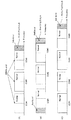
図2(A)(B)(C)は結合コンポーネントキャリアを含む複数コンポーネントキャリアの配置例を示す図である。
Next, a specific description will be given of a communication control method for efficiently filling a vacant band generated when a plurality of component carriers are arranged in a widened system band.
FIGS. 2A, 2B, and 2C are diagrams illustrating examples of arrangement of a plurality of component carriers including combined component carriers.
図2(A)に示されるコンポーネントキャリア配置例では、2つの独立コンポーネントキャリアCC#1、CC#2と、1つの結合コンポーネントキャリアCC#3とが全信号帯域をカバーするように配置されている。3つのコンポーネントキャリアCC#1〜#3におけるノーマルコンポーネントキャリア部分の中心周波数の間隔が300kHzの倍数となるように全信号帯域全体に配置されている。全信号帯域の右端に配置された結合コンポーネントキャリアCC#3は、ノーマルコンポーネントキャリア部分(例えば、20MHz)の右端に追加キャリアであるキャリアセグメント(例えば、1.4MHz)が連続して配置されており、例えば21.4MHzの結合コンポーネントキャリアCC#3を構成している。
In the component carrier arrangement example shown in FIG. 2A, two independent component
図2(B)に示されるコンポーネントキャリア配置例では、同図(A)と同様に3つのコンポーネントキャリアCC#1〜#3であるが、2つの結合コンポーネントキャリアCC#1、CC#3と、1つの独立コンポーネントキャリアCC#2とを組み合わせている。3つのコンポーネントキャリアCC#1〜#3におけるノーマルコンポーネントキャリア部分の中心周波数の間隔が300kHzの倍数となるように信号帯域全体に配置されている。全信号帯域の両端に結合コンポーネントキャリアCC#1とCC#3とが配置されており、低域側の結合コンポーネントキャリアCC#1は低域側端にキャリアセグメントを連続配置し、高域側の結合コンポーネントキャリアCC#3は高域側端にキャリアセグメントを連続配置している。
In the component carrier arrangement example shown in FIG. 2B, there are three component
図2(C)示されるコンポーネントキャリア配置例では、3つの独立コンポーネントキャリアCC#1〜CC#3と、1つの結合コンポーネントキャリアCC#4とを組み合わせている。4つのコンポーネントキャリアCC#1〜#4のノーマルコンポーネントキャリア部分の中心周波数の間隔が300kHzの倍数となるように信号帯域全体に配置されている。全信号帯域において右端に配置された結合コンポーネントキャリアCC#4はノーマルコンポーネントキャリアの高域側端にキャリアセグメントを連続配置している。
In the component carrier arrangement example shown in FIG. 2C, three independent component
図2(A)(B)(C)に示されるように、キャリアセグメントは、必ずノーマルコンポーネントキャリアに隣接して連続的に配置され、ノーマルコンポーネントキャリアに連結して1つのコンポーネントキャリアを構成する。 As shown in FIGS. 2A, 2B, and 2C, the carrier segments are always continuously arranged adjacent to the normal component carrier and are connected to the normal component carrier to constitute one component carrier.
このように、キャリアセグメントがノーマルコンポーネントキャリアに連結して1つのコンポーネントキャリアを構成すれば、キャリアセグメントを独立したコンポーネントキャリアとして新たに定義する必要がなく、オプション数を減らすこともできる。 In this way, if the carrier segment is connected to the normal component carrier to form one component carrier, it is not necessary to newly define the carrier segment as an independent component carrier, and the number of options can be reduced.
また、ノーマルコンポーネントキャリアにキャリアセグメントを連結して結合コンポーネントキャリアを構成したとしても、図3(A)に示すようにLTE端末は結合コンポーネントキャリアをノーマルコンポーネントキャリアとして認識し、図3(B)に示すようにLTE-A端末は結合コンポーネントキャリアとして認識するようにできれば、LTEとのバックワード・コンパチビリティを実現し、かつキャリアの有効活用が実現される。 Also, even if a carrier component is connected to a normal component carrier to form a combined component carrier, the LTE terminal recognizes the combined component carrier as a normal component carrier as shown in FIG. As shown, if the LTE-A terminal can be recognized as a combined component carrier, backward compatibility with LTE can be realized, and effective use of the carrier can be realized.
無線基地局は、LTE端末に対して結合コンポーネントキャリアを割当てたとしても、LTE端末が結合コンポーネントキャリアをノーマルコンポーネントキャリアとして認識してLTE仕様に従った動作が実現されるように通信制御し(リソース制御)、LTE−A端末に対しては結合コンポーネントキャリアを割当てた場合にはLTE−A端末が結合コンポーネントキャリア全体を有効活用できるように通信制御(リソース制御)する。以下、リソース操作の具体例について説明する。 The radio base station performs communication control so that the LTE terminal recognizes the combined component carrier as a normal component carrier and realizes an operation according to the LTE specification even if the combined component carrier is allocated to the LTE terminal (resources). Control), when a combined component carrier is allocated to an LTE-A terminal, communication control (resource control) is performed so that the LTE-A terminal can effectively use the entire combined component carrier. Hereinafter, specific examples of resource operations will be described.
LTE端末及びLTE-A端末に対して区別せずに結合コンポーネントキャリアを割当てる場合、LTE仕様をそのまま適用したのではリソースブロック割当てシグナリングが複雑となる。 When allocating combined component carriers without distinguishing between LTE terminals and LTE-A terminals, resource block allocation signaling becomes complicated if the LTE specifications are applied as they are.
ユーザデータを送信する物理チャネルであるPDSCH、PUSCHについては、基本的にローカライズド送信が適用されるが、ローカライズド送信型の無線リソース割り当てを効率よく行うために、連続するサブキャリアをブロック化したリソースブロック(RB:Resource Block)と呼ばれる無線リソース割り当ての最小単位を定義している。LTEでは、1RBは12サブキャリア×14OFDMシンボルで構成しており、システム帯域となるRB数として{6,15,25,50,75,100}の6種類が規定されている。例えば、5MHzのシステム帯域であれば連続する25個のRBが割り当てられ、20MHzのシステム帯域であれば連続する100個のRBが割り当てられる。 For PDSCH and PUSCH, which are physical channels that transmit user data, localized transmission is basically applied. However, in order to efficiently allocate localized transmission type radio resources, continuous subcarriers are blocked. A minimum unit of radio resource allocation called a resource block (RB) is defined. In LTE, one RB is composed of 12 subcarriers × 14 OFDM symbols, and six types of {6, 15, 25, 50, 75, 100} are defined as the number of RBs serving as a system band. For example, if the system bandwidth is 5 MHz, 25 consecutive RBs are assigned, and if the system bandwidth is 20 MHz, 100 consecutive RBs are assigned.
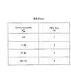
無線基地局から端末に対してRB割当て情報を通知する必要があるが、オーバーヘッド低減のために、RBG(Resource Block Group)が定義されている。すなわち、図4に示すようにシステム帯域(RB数)とRBGサイズとを対応させたテーブルを定めており、RBGサイズで規定されるRBグループを一まとめにしてRB割当て情報を通知する。ところが、図4に示すテーブル(LTE仕様)を用いてRBGサイズを決定したのでは、システム帯によってはノーマルコンポーネントキャリアと結合コンポーネントキャリアとでRBGサイズが変化してしまう。たとえば、図5(A)に示すように、5MHzのノーマルコンポーネントキャリアに1.4MHzのキャリアセグメントを追加して構成された結合コンポーネントキャリアの場合、ノーマルコンポーネントキャリア部分に関してはRB数25であるので図4のテーブルに従えばRBGサイズは2である(図5(B))。一方、キャリアセグメントまで含んだ全体(結合コンポーネントキャリア)ではRB数31(=25+6)であるので図4のテーブルに従えばRBGサイズは3である(図5(C))。したがって、LTE端末に対してはRBGサイズとして2を通知するが、LTE-A端末に対してはRBGサイズとして3を通知する必要がある。このように、図4に示すLTE仕様のテーブルを用いてRBGサイズを決めたのでは、スケジューラにおいてリソースブロック割当てが複雑化するか、割り当てないRBが生じてしまい、効率が劣化してしまう。 Although it is necessary to notify the RB allocation information from the radio base station to the terminal, RBG (Resource Block Group) is defined to reduce overhead. That is, as shown in FIG. 4, a table in which system bandwidth (number of RBs) is associated with RBG size is defined, and RB allocation information is notified as a group of RB groups defined by the RBG size. However, if the RBG size is determined using the table shown in FIG. 4 (LTE specifications), the RBG size changes between the normal component carrier and the combined component carrier depending on the system band. For example, as shown in FIG. 5A, in the case of a combined component carrier configured by adding a carrier segment of 1.4 MHz to a normal component carrier of 5 MHz, the number of RBs is 25 for the normal component carrier portion. According to the table of 4, the RBG size is 2 (FIG. 5B). On the other hand, since the total including the carrier segment (combined component carrier) has 31 RBs (= 25 + 6), the RBG size is 3 according to the table of FIG. 4 (FIG. 5C). Therefore, although 2 is reported as the RBG size to the LTE terminal, it is necessary to notify 3 as the RBG size to the LTE-A terminal. As described above, when the RBG size is determined using the LTE specification table shown in FIG. 4, resource block allocation is complicated in the scheduler, or RBs that are not allocated are generated, and efficiency is deteriorated.
本発明は、リソースブロック割当てシグナリングの複雑化および低効率化を解消するために改善されたテーブル構成を提案する。すなわち、ノーマルコンポーネントキャリア(NsRB数)と、当該ノーマルコンポーネントキャリア(RB数=Ns個)にキャリアセグメント(RB数=Ncs個)を結合した結合コンポーネントキャリア(RB数=Ns+Ncs)とで、RBGサイズが変化しないように、システム帯域(RB数)とRBGサイズとの対応関係を修正する(図6参照)。 The present invention proposes an improved table configuration to eliminate the complexity and low efficiency of resource block allocation signaling. That is, with the normal component carrier (NsRB number) and the combined component carrier (RB number = Ns + Ncs) in which the normal component carrier (RB number = Ns) is combined with the carrier segment (RB number = Ncs), the RBG size is The correspondence between the system band (number of RBs) and the RBG size is corrected so as not to change (see FIG. 6).
このようなテーブルに基づいてRBGサイズを決定することにより、図5(D)に示されるように、ノーマルコンポーネントキャリア(5MHz)のシステム帯域に対応して決定されるRBGサイズが「2」となり(LTE端末用)、結合コンポーネントキャリア(5.14MHz)のシステム帯域に対応して決定されるRBGサイズが「2」となる。よって、LTE端末とLTE−A端末とでRBGサイズを同一にすることができる。 By determining the RBG size based on such a table, as shown in FIG. 5D, the RBG size determined corresponding to the system band of the normal component carrier (5 MHz) is “2” ( The RBG size determined corresponding to the system band of the LTE component and the combined component carrier (5.14 MHz) is “2”. Therefore, the RBG size can be the same between the LTE terminal and the LTE-A terminal.
図6はLTE端末とLTE−A端末とでRBGの割り当てが同一のRBGサイズとなるように改善されたテーブル構成を示す図である。LTEではシステム帯域(RB数)が、RB数=6(1.4MHz)、RB数=15(3MHz)、RB数=25(5MHz)、RB数=50(10MHz)、RB数=75(15MHz)、RB数=100(20MHz)の6段階である。そこで、システム帯域(RB数)がRB数=11より上の領域では、システム帯域(RB数)が次段階となるまでRBGサイズを変化させないように制御する。 FIG. 6 is a diagram illustrating a table configuration improved so that the RBG allocation is the same RBG size between the LTE terminal and the LTE-A terminal. In LTE, the system bandwidth (number of RBs) is RB number = 6 (1.4 MHz), RB number = 15 (3 MHz), RB number = 25 (5 MHz), RB number = 50 (10 MHz), RB number = 75 (15 MHz) ), The number of RBs = 100 (20 MHz). Therefore, in the region where the system band (number of RBs) is higher than the number of RBs = 11, control is performed so that the RBG size is not changed until the system band (number of RBs) reaches the next stage.
これにより、キャリアセグメントが連結先のノーマルコンポーネントキャリアのサイズを超えない範囲であれば、LTEとLTE-Aとが同一のRBGサイズとなる。なお、キャリアセグメントが連結先のノーマルコンポーネントキャリアのサイズを超える場合には、同サイズのノーマルコンポーネントキャリアを1つ追加すればよいので、キャリアセグメントが連結先のノーマルコンポーネントキャリアのサイズを超えることはない。 Thereby, if the carrier segment is within a range that does not exceed the size of the normal component carrier of the connection destination, LTE and LTE-A have the same RBG size. If the carrier segment exceeds the size of the normal component carrier of the connection destination, it is only necessary to add one normal component carrier of the same size, so the carrier segment does not exceed the size of the normal component carrier of the connection destination. .
たとえば、図6に示すテーブルにおいて、システム帯域がRB数=10を超えてからRB数=50(10MHz)になるまではRBGサイズが2に維持されているので、システム帯域がRB数=25のノーマルコンポーネントキャリアにRB数=6のキャリアセグメントを追加しても、LTE端末とLTE−A端末とで割り当てるRBGが同一サイズとなる。 For example, in the table shown in FIG. 6, since the RBG size is maintained at 2 until the system band exceeds the number of RBs = 10 and the number of RBs = 50 (10 MHz), the system band is equal to the number of RBs = 25. Even if a carrier segment with the number of RBs = 6 is added to the normal component carrier, the RBGs allocated by the LTE terminal and the LTE-A terminal have the same size.
したがって、無線基地局は、結合コンポーネントキャリアを端末に割当てる場合、リソースブロック割当ての際のRBGサイズがLTE端末とLTE−A端末とで同一サイズとなるので、リソースブロック割当ての複雑化、および低効率化を防止できる。 Therefore, when the radio base station allocates the combined component carrier to the terminal, the RBG size at the time of resource block allocation becomes the same size in the LTE terminal and the LTE-A terminal, so that the resource block allocation becomes complicated and low efficiency Can be prevented.
また、下りリンク制御情報を伝送するためのPDCCHは、コンポーネントキャリアの先頭第1〜第3OFDMシンボルに配置される。結合コンポーネントキャリアのキャリアセグメントでPDCCHを伝送すると、LTE端末でPDCCHを受信できないためPDSCH、PUSCHを復号できない事態になる。そこで、PDCCHはノーマルコンポーネントキャリア部分でのみ送信し、キャリアセグメントでは送信しないように制御する必要がある。ところが、キャリアセグメントにPDCCHを割当てないこととした場合、PDSCHの開始位置がRB間で異なるケースが発生する。 Also, the PDCCH for transmitting the downlink control information is arranged in the first to third OFDM symbols of the component carrier. If PDCCH is transmitted in the carrier segment of the combined component carrier, PDSCH and PUSCH cannot be decoded because the LTE terminal cannot receive PDCCH. Therefore, it is necessary to control so that PDCCH is transmitted only in the normal component carrier part and not transmitted in the carrier segment. However, when the PDCCH is not allocated to the carrier segment, a case where the PDSCH start position differs between RBs occurs.
本発明は、ノーマルコンポーネントキャリアにキャリアセグメントを連結して結合コンポーネントキャリアが構成されている場合に、ノーマルコンポーネントキャリア部分だけに制御チャネルを割当て、LTE−A端末に対してキャリアセグメントの先頭RBを共有データチャネルの開始位置として順番にユーザデータをマッピングする。または、キャリアセグメントのうち制御チャネルが割当てられているシンボル位置までは無送信とし、キャリアセグメントのPDSCHの開始位置をノーマルコンポーネントキャリアと揃える。 The present invention assigns a control channel only to the normal component carrier part and shares the head RB of the carrier segment to the LTE-A terminal when the combined component carrier is configured by connecting the carrier segment to the normal component carrier. User data is mapped in order as the start position of the data channel. Alternatively, no transmission is performed up to the symbol position to which the control channel is allocated in the carrier segment, and the PDSCH start position of the carrier segment is aligned with the normal component carrier.
図7は、キャリアセグメントの先頭RE(Rerouce Element、1サブキャリア×1OFDMシンボルから構成)を共有データチャネルの開始位置として順番にマッピングする方法が示されている。同図に示すリソース割当方法では、制御チャネルであるPDCCHを、ノーマルコンポーネントキャリアの先頭第1及び第2OFDMシンボルで伝送するが、キャリアセグメントでは先頭第1及び第2OFDMシンボルでPDCCHを伝送しないようにリソース割り当てを制御している。共有データチャネルであるPDSCHは、キャリアセグメントの先頭REを開始位置として順番にマッピングしている。そして、キャリアセグメントの最後尾(RE=144)までマッピングしたら、マッピング位置を第3OFDMシンボル(制御チャネルを割当てた第1及び第2OFDMシンボルの次後続シンボル)であってノーマルコンポーネントキャリアにおける周波数方向の先頭位置(RB=145)から周波数方向に順番にマッピングする。PDSCHはキャリアセグメントまでマッピングする。ただし、LTE端末の場合、キャリアセグメントは認識できないので、キャリアセグメントへの共有データチャネルのマッピングは行わない。 FIG. 7 shows a method of sequentially mapping the first RE (Rerouce Element, composed of 1 subcarrier × 1 OFDM symbol) of the carrier segment as the start position of the shared data channel. In the resource allocation method shown in the figure, the control channel PDCCH is transmitted using the first first and second OFDM symbols of the normal component carrier, but the carrier segment does not transmit the PDCCH using the first first and second OFDM symbols. Controls allocation. PDSCH, which is a shared data channel, is mapped in order starting from the start RE of the carrier segment. After mapping to the end of the carrier segment (RE = 144), the mapping position is the third OFDM symbol (the next succeeding symbol of the first and second OFDM symbols to which the control channel is assigned) and the head in the frequency direction of the normal component carrier Mapping is performed in order from the position (RB = 145) in the frequency direction. PDSCH maps up to the carrier segment. However, in the case of an LTE terminal, since the carrier segment cannot be recognized, the shared data channel is not mapped to the carrier segment.
このように、ノーマルコンポーネントキャリアにキャリアセグメントが連結された結合コンポーネントキャリアの場合に、制チャネルはLTE仕様と同様に、ノーマルコンポーネントキャリア部分(先頭1から3OFDMシンボル)でのみで送信してキャリアセグメントでは制チャネルを送信しないようにしたので、いずれのコンポーネントキャリア構成であっても制御チャネルをノーマルコンポーネントキャリアに収容することができる。 In this way, in the case of a combined component carrier in which a carrier segment is connected to a normal component carrier, the control channel is transmitted only in the normal component carrier part (from the first 1 to 3 OFDM symbols) as in the LTE specification. Since the control channel is not transmitted, the control channel can be accommodated in the normal component carrier in any component carrier configuration.
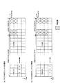
図8(A)(B)はキャリアセグメントのPDSCHの開始位置をノーマルコンポーネントキャリアと揃えてマッピングするリソース割当て方法が示されている。図8(A)は制御チャネルに2OFDMシンボルを割当てた例であり、図8(B)は制御チャネルに3OFDMシンボルを割当てた例である。このリソース割当て方法は、制御チャネルであるPDCCHは、ノーマルコンポーネントキャリア部分(先頭1-3OFDMシンボル)で伝送しているが、キャリアセグメントではPDCCHを伝送しない。また、ノーマルコンポーネントキャリア部分において制御チャネルが割当てられているOFDMシンボルと同一のOFDMシンボル(キャリアセグメントの先頭から第2又は第3OFDMシンボル)位置までは共有データチャネルであるPDSCHも送信しない無送信区間としている。そして、キャリアセグメントのPDSCHの開始位置をノーマルコンポーネントキャリアと揃えて、第2OFDMシンボル(同図(A))又は第3OFDMシンボル(同図(B))としている。ただし、LTE端末の場合、キャリアセグメントは認識できないので、キャリアセグメントへの共有データチャネルのマッピングは行わない。 FIGS. 8A and 8B show a resource allocation method in which the PDSCH start position of the carrier segment is mapped in alignment with the normal component carrier. FIG. 8A shows an example in which 2 OFDM symbols are assigned to the control channel, and FIG. 8B shows an example in which 3 OFDM symbols are assigned to the control channel. In this resource allocation method, the PDCCH that is the control channel is transmitted in the normal component carrier part (first 1-3 OFDM symbol), but the PDCCH is not transmitted in the carrier segment. In addition, as a non-transmission period in which PDSCH which is a shared data channel is not transmitted from the position of the OFDM symbol (the second or third OFDM symbol from the beginning of the carrier segment) to the same OFDM symbol to which the control channel is assigned in the normal component carrier Yes. Then, the PDSCH start position of the carrier segment is aligned with that of the normal component carrier to form the second OFDM symbol (FIG. (A)) or the third OFDM symbol ((B)). However, in the case of an LTE terminal, since the carrier segment cannot be recognized, the shared data channel is not mapped to the carrier segment.
このように、ノーマルコンポーネントキャリア部分において制御チャネルが割当てられている先頭数OFDMシンボルまでは、キャリアセグメントにおいて共有データチャネルを送信しない無送信区間とし、PDSCHの開始位置をキャリアセグメントとノーマルコンポーネントキャリアとで揃えるようにリソース割り当て制御することで、LTE仕様を踏襲したリソース割り当てが可能になる。 Thus, up to the first number of OFDM symbols to which the control channel is assigned in the normal component carrier part, the shared segment is not transmitted in the carrier segment, and the PDSCH start position is determined by the carrier segment and the normal component carrier. By performing resource allocation control so as to align, resource allocation following the LTE specification becomes possible.
また、LTE仕様では、ユーザ共通制御情報とユーザ固有制御情報の2種類の制御情報が規定されている。この制御情報のビット数は,後述するように,RB数によって決まるため,ユーザ共通制御情報のビット数をキャリアセグメントを含めて決定してしまうと、LTE端末では受信できない不都合が生じる。したがって、ユーザ共通制御情報はノーマルコンポーネントキャリアでのみ送信し、ユーザ固有PDCCHはLTE−A端末に対してのみキャリアセグメントまで使用して送信する制御が適していると考えられる。以下、具体的に説明する。 In the LTE specification, two types of control information, user common control information and user specific control information, are defined. As will be described later, since the number of bits of this control information is determined by the number of RBs, if the number of bits of user common control information including the carrier segment is determined, there is a problem that the LTE terminal cannot receive. Therefore, it is considered that the user common control information is transmitted only on the normal component carrier, and the user-specific PDCCH is transmitted using only the carrier segment only to the LTE-A terminal. This will be specifically described below.
図9はLTE仕様によるPDCCH送信の概念図であり、図10はPDCCH受信の概念図である。図9に示すように、無線基地局は、同一サブフレームに多重されるユーザ端末の下りリンク制御情報(DCI:Downlink Control Information)に対し、ユーザID(UE-ID)でマスクしたCRCを付与した後、チャネル符号化する。また、各ユーザ端末の受信品質に応じて、72、144、288、576ビットにレートマッチングする(72ビット又は576ビットの場合、符号化率2/3,1/12に相当)。ここで、72ビットを基本単位(CCE:Control Channel Element)と定義し、定義した4種類のCCE数={1,2,4,8}の中から受信品質に応じて最適なCCE数が決定される。さらに、QPSK変調後、複数ユーザ端末の制御情報を多重し(CCE multiplexing)、周波数ダイバーシチ効果を得るために、REG(Resource Element Groupの略で4REから構成される)単位でインターリーブする(CCE interleaving)。その後、サブフレームの先頭にマッピングする。 FIG. 9 is a conceptual diagram of PDCCH transmission according to LTE specifications, and FIG. 10 is a conceptual diagram of PDCCH reception. As shown in FIG. 9, the radio base station assigns a CRC masked with a user ID (UE-ID) to downlink control information (DCI: Downlink Control Information) of user terminals multiplexed in the same subframe. After that, channel coding is performed. Also, rate matching is performed on 72, 144, 288, and 576 bits according to the reception quality of each user terminal (corresponding to a coding rate of 2/3 and 1/12 in the case of 72 bits or 576 bits). Here, 72 bits are defined as a basic unit (CCE: Control Channel Element), and the optimum number of CCEs is determined from the defined four types of CCEs = {1, 2, 4, 8} according to the reception quality Is done. Furthermore, after QPSK modulation, the control information of multiple user terminals is multiplexed (CCE multiplexing), and interleaved in units of REG (abbreviation of Resource Element Group, consisting of 4RE) (CCE interleaving) in order to obtain the frequency diversity effect. . Then, it maps to the head of a sub-frame.
図10に示すように、ユーザ端末は、サブフレーム先頭の1〜3OFDMシンボルにマッピングされたPDCCHをデインターリーブする。ユーザ端末は、レートマッチングパラメータ(CCE数)、及びCCEの開始位置が不明であるため、CCE単位でブラインドデコーディングし、ユーザIDでマスクされたCRCがOKとなるCCEを探索する。図10に示される例は、端末UE#3の場合であり、全ての可能性を試し、CCE#4において検出成功している。
As illustrated in FIG. 10, the user terminal deinterleaves the PDCCH mapped to the first to third OFDM symbols of the subframe. Since the user terminal does not know the rate matching parameter (the number of CCEs) and the start position of the CCE, the user terminal performs blind decoding in units of CCE and searches for a CCE in which the CRC masked with the user ID is OK. The example shown in FIG. 10 is the case of the
ここで、システム帯域が20MHzのコンポーネントキャリアであれば、CCE数が84にもなるため、全ての可能性を探索するのは端末の負荷が大きい。そこで、ブラインドデコーディングする位置を限定することにより、端末の負荷軽減を図るためのサーチスペースという手法が取り入れられている。 Here, if the component carrier has a system bandwidth of 20 MHz, the number of CCEs is as large as 84, and thus searching for all possibilities is a heavy load on the terminal. Therefore, a technique called a search space for reducing the load on the terminal by limiting the positions for blind decoding is adopted.
図11にブラインドデコーディングする範囲となる2種類のサーチスペースを例示している。上記した通り、LTEでは2種類の制御情報が規定されている。ユーザ共通制御情報は、同一セルに接続している全てのユーザ端末が同時に受信する必要のある情報を伝送する制御チャネルであり、報知情報,ページング情報,送信電力制御信号送信用のリソース割当情報などが伝送される。ユーザ固有制御情報は、1ユーザ端末のみ受信する必要のある情報を伝送する制御チャネルであり、上下リンクの共有データチャネル送信のためのリソース割当情報などが伝送される。図11に示されるように、上記2種類の制御情報に対応してユーザ共有サーチスペースとユーザ固有サーチスペースの2種類のサーチスペースが定義されている。ユーザ共有サーチスペースは、全てのユーザ端末で共通の位置に配置されている(先頭の2CCEであるCCE#1、CCE#2に配置)。ユーザ固有サーチスペースは、ユーザ端末で独立の位置に配置されている(ユーザID及びサブフレーム番号によりランダムに配置)。特に、ユーザ共有サーチスペースは、2種類のフォーマット(1A,1C)をサポートし、セル端のユーザ端末も高品質に受信できるようにするため、4,8CCEアグリゲーションのみを用いる。ブラインドデコーディング数はそれぞれ4,2となる。したがって、トータルで12ブラインドデコーディング数(2サイズ×(4+2))となる。
FIG. 11 exemplifies two types of search spaces that are ranges for blind decoding. As described above, two types of control information are defined in LTE. User common control information is a control channel that transmits information that all user terminals connected to the same cell need to receive simultaneously, such as broadcast information, paging information, resource allocation information for transmission power control signal transmission, etc. Is transmitted. The user-specific control information is a control channel for transmitting information that needs to be received by only one user terminal, and resource allocation information for transmitting a shared data channel for uplink and downlink is transmitted. As shown in FIG. 11, two types of search spaces, a user shared search space and a user specific search space, are defined corresponding to the two types of control information. The user shared search space is arranged at a common position in all user terminals (arranged in
上記したPDCCH送信において、LTE端末はノーマルコンポーネントキャリアのRB数(Ns)でDCIフォーマット1A/1Cのビット数が決まり、LTE−A端末はノーマルコンポーネントキャリアにキャリアセグメントを追加した連結コンポーネントキャリアのRB数(Ns+Ncs)でDCIフォーマット1A/1Cのビット数が決まる。そのため、ノーマルコンポーネントキャリアと連結コンポーネントキャリアとでビット数が異なることになるが、割り当てられる連結コンポーネントキャリアのビット数に応じてユーザ共有サーチスペースのビット数を計算したのではLTE端末ではユーザ共有サーチスペースの情報を受信できない可能性がある。そこで、かかる問題を解決するために以下の対策を講じることが望ましい。 In the PDCCH transmission described above, the LTE terminal determines the number of bits of DCI format 1A / 1C by the number of RBs (Ns) of normal component carriers, and the LTE-A terminal has the number of RBs of concatenated component carriers in which a carrier segment is added to the normal component carrier. (Ns + Ncs) determines the number of bits of the DCI format 1A / 1C. Therefore, although the number of bits is different between the normal component carrier and the connected component carrier, the number of bits of the user shared search space is calculated according to the number of bits of the assigned connected component carrier. Information may not be received. Therefore, it is desirable to take the following measures to solve this problem.
本発明は、ノーマルコンポーネントキャリアのみに対応可能なLTE端末と連結コンポーネントキャリアまで対応可能なLTE-A端末とを対象としてPDCCHを送信する場合、ユーザ共有サーチスペース及びユーザ固有サーチスペースはノーマルコンポーネントキャリアに割当て、ユーザ共有サーチスペースで送信する制御情報のビット数は、ノーマルコンポーネントキャリアのサイズに基づいて計算し、ユーザ固有サーチスペースで割当て情報が通知される情報(PDSCH,PUSCH等のデータ)の割当てビット数はユーザ端末で対応可能なそれぞれのシステム帯域のサイズに基づいて計算する。 In the present invention, when a PDCCH is transmitted for an LTE terminal that supports only a normal component carrier and an LTE-A terminal that can support even a connected component carrier, the user shared search space and the user specific search space are in the normal component carrier. The number of bits of control information to be transmitted in the allocation and user shared search space is calculated based on the size of the normal component carrier, and the allocation bits of information (PDSCH, PUSCH, etc.) for which the allocation information is notified in the user-specific search space The number is calculated based on the size of each system band that can be handled by the user terminal.
これにより、PDCCHを受信したLTE端末においてユーザ共有サーチスペースの情報を確実に受信することができる。 Thereby, the information of the user shared search space can be reliably received in the LTE terminal that has received the PDCCH.
また、LTEのような、広帯域のシステム帯域幅を持つ無線通信における物理チャネルの送信法には、ディストリビューテッド送信とローカライズド送信法がある。 In addition, there are distributed transmission methods and localized transmission methods as physical channel transmission methods in wireless communication having a wide system bandwidth such as LTE.
図12にディストリビューテッド送信とローカライズド送信法の概要を示す。
図12(A)にはバーチャルリソースブロック(VRB: Virtual Resource Block)の配列を示している。ローカライズド送信法の場合、図12(B)に示すように、バーチャルリソースブロックをシステム帯域に対してインデックス順に物理リソースブロックへマッピングする。
FIG. 12 shows an overview of distributed transmission and localized transmission methods.
FIG. 12A shows an array of virtual resource blocks (VRB). In the localized transmission method, as shown in FIG. 12B, virtual resource blocks are mapped to physical resource blocks in the index order with respect to the system band.
ディストリビューテッド送信法の場合、図12(C)に示すように、互いに離れた2つのVRBを2分割し、分割した2つのVRBをペアにして物理リソースブロックへマッピングする。図12(C)には1RBが割り当てられた場合が示されており、インデックス0のバーチャルリソースブロックである0VRBが2分割され、第1スロットでは物理リソースブロックの0PRBにマッピングされ、第2スロットではNgapだけ離れた物理リソースブロック位置の12PRBにマッピングされている。また、ペアとなる2VRBも2分割され、第1スロットでは物理リソースブロックの12PRBにマッピングされ、第2スロットでは物理リソースブロックの0PRBにマッピングされている。また、図示されていないが、たとえば2RBが割り当てられた場合、0,1VRBは第1スロットでは物理リソースブロックのPRB0,6にマッピングされ、第2スロットでは物理リソースブロックのPRB12,18にマッピングされる。このように、ディストリビューテッド送信法の場合、1,2RBの割当てで、2次、4次の周波数ダイバーシチ効果を得ることが可能になる。また,このNgapの値は,RB数が大きいほど大きく設定する必要があるため,RB数に依存する。
In the case of the distributed transmission method, as shown in FIG. 12C, two VRBs that are separated from each other are divided into two, and the two divided VRBs are paired and mapped to physical resource blocks. FIG. 12C shows a case where 1 RB is allocated. 0VRB, which is a virtual resource block with
上記した連結コンポーネントキャリアにおいて、ディストリビューテッド送信する場合、第1スロットではノーマルコンポーネントキャリアにマッピングされ、第2スロットではキャリアセグメントにマッピングされる可能性がある。LTE端末ではキャリアセグメントにマッピングされた部分は認識できない問題がある。この問題の解決策として、LTE-A端末に対してはキャリアセグメントまで含めたディストリビューテッド送信を可能とし、LTE端末に対してはノーマルコンポーネントキャリアに閉じたディストリビューテッド送信を可能とすることも考えられる。しかし、LTEとLTE-Aとでディストリビューテッド送信のときの構成が異なるのは複雑化を伴う。 In the above-described connected component carrier, when distributed transmission is performed, the first slot may be mapped to a normal component carrier, and the second slot may be mapped to a carrier segment. There is a problem that the LTE terminal cannot recognize the portion mapped to the carrier segment. As a solution to this problem, it is also possible to enable distributed transmission including the carrier segment for LTE-A terminals and to enable distributed transmission closed to normal component carriers for LTE terminals. . However, the difference in the configuration for distributed transmission between LTE and LTE-A is complicated.
本発明は、ノーマルコンポーネントキャリアの一端にキャリアセグメントが連結されて連結コンポーネントキャリアを構成する場合に、ノーマルコンポーネントキャリアの範囲内でのみディストリビューテッド送信をサポートし、キャリアセグメントではディストリビューテッド送信しないように無線リソースを割り当てる。 In the present invention, when a carrier segment is connected to one end of a normal component carrier to form a connected component carrier, distributed transmission is supported only within the range of the normal component carrier, and distributed transmission is not performed in the carrier segment. Allocate resources.
図13は連結コンポーネントキャリアに対してもノーマルコンポーネントキャリア部分でのみディストリビューテッド送信をサポートする概念図を示している。図12(A)に示すインデックス0のバーチャルリソースブロックである0VRBが2分割され、第1スロットでは物理リソースブロックの0PRBにマッピングされ、第2スロットではNgapだけ離れた物理リソースブロック位置の12PRBにマッピングされている。また、6VRBも2分割され、第1スロットでは物理リソースブロックの6PRBにマッピングされ、第2スロットでは物理リソースブロックの19PRBにマッピングされている。このように、全てのバーチャルリソースブロックはノーマルコンポーネントキャリア(25RB)内の物理リソースブロックを割当て、キャリアセグメント(6RB)ではディストリビューテッド送信しないように制御する。
FIG. 13 is a conceptual diagram for supporting distributed transmission only in the normal component carrier portion for the connected component carriers. 0VRB, which is the virtual resource block with
これにより、ディストリビューテッド送信のときの構成が異なることによる複雑化を排除でき、LTE端末においてディストリビューテッド送信された信号を正しく復号することが可能になる。 As a result, complications due to different configurations at the time of distributed transmission can be eliminated, and a signal transmitted in a distributed manner in an LTE terminal can be correctly decoded.
以上の説明では、キャリアセグメントを追加した場合の下りリンクの通信制御について改善策を説明したが、上りリンクについても以下の改善策を提案する。
LTEにおける上りリンク物理チャネル構成は、制御チャネルであるPUCCHをシステム帯域の両端に配置し、周波数ダイバーシチ効果を得るためにサブフレーム内周波数ホッピングを適用している。ノーマルコンポーネントキャリアの一端にキャリアセグメントが連結される連結コンポーネントキャリアの場合、LTE仕様にしたがってPUCCHをシステム帯域の両端に配置すると、少なくとも一方のPUCCHがキャリアセグメント上に配置される。LTE端末はキャリアセグメントで送信できないので、PUCCHを正しく送れない不都合が生じる。
In the above description, an improvement measure has been described for downlink communication control when a carrier segment is added, but the following improvement measure is also proposed for the uplink.
In the uplink physical channel configuration in LTE, PUCCH that is a control channel is arranged at both ends of the system band, and intra-subframe frequency hopping is applied in order to obtain a frequency diversity effect. In the case of a connected component carrier in which a carrier segment is connected to one end of a normal component carrier, when PUCCH is arranged at both ends of the system band in accordance with LTE specifications, at least one PUCCH is arranged on the carrier segment. Since the LTE terminal cannot transmit in the carrier segment, there arises a disadvantage that PUCCH cannot be sent correctly.
本発明は、ノーマルコンポーネントキャリアの一端にキャリアセグメントが連結されて連結コンポーネントキャリアを構成する場合に、ノーマルコンポーネントキャリアの両端に上りリンクの制御チャネルを配置し、ノーマルコンポーネントキャリアでのみサブフレーム内周波数ホッピングをサポートする。 In the present invention, when a carrier segment is connected to one end of a normal component carrier to form a connected component carrier, uplink control channels are arranged at both ends of the normal component carrier, and intra-subframe frequency hopping is performed only on the normal component carrier. Support.
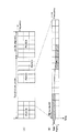
図14(A)はノーマルコンポーネントキャリアの一端にキャリアセグメントが連結されて連結コンポーネントキャリアを構成する場合に、ノーマルコンポーネントキャリアの両端に上りリンクの制御チャネルを配置する例を示す図である。ノーマルコンポーネントキャリアの両端に配置されたPUCCH間でサブフレーム内周波数ホッピングを適用する。キャリアセグメントにはPUSCHを割り当てる。キャリアセグメントでのPUSCHの伝送は、Clustered DFT(Discrete Fourier Transform)-拡散OFDMでのみサポートすることとする。Clustered DFT-拡散OFDMは、OFDM変調の前に送信信号をDFT拡散することによって周波数領域に変換し、DFT後の送信信号符号化データ・シンボルの各周波数成分を複数の周波数ブロック(Cluster)に分割した後,システム帯域幅に相当する帯域幅を持つIFFTのサブキャリア位置に挿入し、他の周波数成分は0を設定する。 FIG. 14A is a diagram illustrating an example in which uplink control channels are arranged at both ends of a normal component carrier when a carrier segment is connected to one end of a normal component carrier to form a connected component carrier. Intra-frame frequency hopping is applied between PUCCHs arranged at both ends of the normal component carrier. PUSCH is allocated to the carrier segment. PUSCH transmission in the carrier segment is supported only by Clustered DFT (Discrete Fourier Transform) -spread OFDM. Clustered DFT-spread OFDM converts the transmission signal to the frequency domain by DFT spreading before OFDM modulation, and divides each frequency component of the transmission signal encoded data symbol after DFT into multiple frequency blocks (Cluster) After that, it is inserted at the IFFT subcarrier position having a bandwidth corresponding to the system bandwidth, and 0 is set for the other frequency components.
これにより、上りリンクの制御チャネルであるPUCCHの位置がLTEとLTE−Aとで共通化されるので、オーバーへッドを小さくすることができる。 Thereby, since the position of PUCCH which is an uplink control channel is shared by LTE and LTE-A, an overhead can be made small.
また、上りリンクの物理チャネルにおいて、PUSCHについても周波数ダイバーシチ効果を得るために周波数ホッピングさせている。このとき、PUSCHのホッピング先がキャリアセグメントであるとLTE端末がPUSCHを送信できない不具合が生じる。
本発明は、ノーマルコンポーネントキャリアでのみPUSCHのサブフレーム内周波数ホッピングをサポートし、キャリアセグメントをホッピング先にしないようにリソース制御する。
図14(B)は、ノーマルコンポーネントキャリアの一端にキャリアセグメントが連結されて連結コンポーネントキャリアを構成する場合に、PUSCHの周波数ホッピング先がノーマルコンポーネントキャリアの範囲内となるように無線リソースを割り当てる例を示している。
以下、本発明の実施の形態について、添付図面を参照して詳細に説明する。ここでは、LTEシステムとLTE−Aシステムとが重複して構築されている移動通信システムにおける無線基地局装置及び移動端末装置について説明する。
Further, in the uplink physical channel, PUSCH is also subjected to frequency hopping in order to obtain a frequency diversity effect. At this time, if the PUSCH hopping destination is a carrier segment, the LTE terminal cannot transmit the PUSCH.
The present invention supports PUSCH intra-subframe frequency hopping only for normal component carriers, and performs resource control so that the carrier segment is not a hopping destination.
FIG. 14B shows an example in which radio resources are allocated so that the PUSCH frequency hopping destination is within the range of the normal component carrier when a carrier segment is connected to one end of the normal component carrier to form a connected component carrier. Show.
Hereinafter, embodiments of the present invention will be described in detail with reference to the accompanying drawings. Here, a radio base station apparatus and a mobile terminal apparatus in a mobile communication system in which the LTE system and the LTE-A system are constructed in an overlapping manner will be described.
図15を参照しながら、本発明の実施例に係る移動端末装置(UE)10及び基地局装置(Node B)20を有する移動通信システム1について説明する。図15は、本実施の形態に係る移動端末装置10及び基地局装置20及びを有する移動通信システム1の構成を説明するための図である。なお、図15に示す移動通信システム1は、上記した通り、LTEシステム及びLTE−Aシステムが包含されるシステムである。LTE−Aは、IMT−Advancedと呼ばれても良いし、4Gと呼ばれても良い。
A
図15に示すように、移動通信システム1は、基地局装置20と、この基地局装置20と通信する複数の移動端末装置10(101、102、103、・・・10n、nはn>0の整数)とを含んで構成されている。基地局装置20は、上位局装置30と接続され、この上位局装置30は、コアネットワーク40と接続される。移動端末装置10は、セル50において基地局装置20と通信を行っている。なお、上位局装置30には、例えば、アクセスゲートウェイ装置、無線ネットワークコントローラ(RNC)、モビリティマネジメントエンティティ(MME)等が含まれるが、これに限定されるものではない。
As shown in FIG. 15, the
各移動端末装置(101、102、103、・・・10n)は、LTE端末及びLTE−A端末を含むが、以下においては、特段の断りがない限り移動端末装置10として説明を進める。また、説明の便宜上、基地局装置20と無線通信するのは移動端末装置10であるものとして説明するが、より一般的には移動端末装置も固定端末装置も含むユーザ装置(UE:User Equipment)でよい。
Each mobile terminal device (10 1 , 10 2 , 10 3 ,... 10 n ) includes an LTE terminal and an LTE-A terminal. In the following description, unless otherwise specified, the mobile
移動通信システム1においては、無線アクセス方式として、下りリンクについてはOFDMA(直交周波数分割多元接続)が、上りリンクについてはSC−FDMA(シングルキャリア−周波数分割多元接続)が適用される。OFDMAは、周波数帯域を複数の狭い周波数帯域(サブキャリア)に分割し、各サブキャリアにデータをマッピングして通信を行うマルチキャリア伝送方式である。SC−FDMAは、システム帯域を端末毎に1つ又は連続したリソースブロックからなる帯域に分割し、複数の端末が互いに異なる帯域を用いることで、端末間の干渉を低減するシングルキャリア伝送方式である。
In the
ここで、LTEシステムにおける通信チャネルについて説明する。下りリンクについては、各移動端末装置10で共有されるPDSCHと、下りL1/L2制御チャネル(PDCCH、PCFICH、PHICH)とが用いられる。このPDSCHにより、ユーザデータ、すなわち、通常のデータ信号が伝送される。送信データは、このユーザデータに含まれる。なお、基地局装置20で移動端末装置10に割り当てたコンポーネントキャリア情報やスケジューリング情報は、L1/L2制御チャネルにより移動端末装置10に通知される。
Here, a communication channel in the LTE system will be described. For downlink, PDSCH shared by each mobile
上りリンクについては、各移動端末装置10で共有して使用されるPUSCHと上りリンクの制御チャネルであるPUCCH(Physical Uplink Control Channel)とが用いられる。このPUSCHにより、ユーザデータが伝送される。また、PUCCHは、サブフレーム内周波数ホッピングが適用され、下りリンクの無線品質情報(CQI:Channel Quality Indicator)、ACK/NACK等が伝送される。
For the uplink, a PUSCH shared and used by each mobile
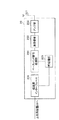
図16を参照しながら、本実施の形態に係る基地局装置20の全体構成について説明する。基地局装置20は、送受信アンテナ201と、アンプ部202と、送受信部203と、ベースバンド信号処理部204と、呼処理部205と、伝送路インターフェース206とを備えている。
The overall configuration of
下りリンクにより基地局装置20から移動端末装置10に送信されるユーザデータは、基地局装置20の上位に位置する上位局装置30から伝送路インターフェース206を介してベースバンド信号処理部204に入力される。
User data transmitted from the
ベースバンド信号処理部204において、PDCPレイヤの処理、ユーザデータの分割・結合、RLC(radio link control)再送制御の送信処理などのRLCレイヤの送信処理、MAC(Medium Access Control)再送制御、例えば、HARQ(Hybrid Automatic Repeat reQuest)の送信処理、スケジューリング、伝送フォーマット選択、チャネル符号化、逆高速フーリエ変換(IFFT:Inverse Fast Fourier Transform)処理、プリコーディング処理が行われる。また、下りリンク制御チャネルである物理下りリンク制御チャネルの信号に関しても、チャネル符号化や逆高速フーリエ変換等の送信処理が行われて、送受信部203に転送される。
In the baseband
また、ベースバンド信号処理部204は、上述した報知チャネルにより、同一セル50に接続する移動端末装置10に対して、各移動端末装置10が基地局装置20との無線通信するための制御情報を通知する。当該セル50における通信のための報知情報には、例えば、上りリンク又は下りリンクにおけるシステム帯域幅や、PRACHにおけるランダムアクセスプリアンブルの信号を生成するためのルート系列の識別情報(Root Sequence Index)等が含まれる。
In addition, the baseband
送受信部203においては、ベースバンド信号処理部204から出力されたベースバンド信号を無線周波数帯に変換する周波数変換処理が施され、その後、アンプ部202で増幅されて送受信アンテナ201より送信される。
In the transmission /
一方、上りリンクにより移動端末装置10から基地局装置20に送信される信号については、送受信アンテナ201で受信された無線周波数信号がアンプ部202で増幅され、送受信部203で周波数変換されてベースバンド信号に変換され、ベースバンド信号処理部204に入力される。
On the other hand, for a signal transmitted from the mobile
ベースバンド信号処理部204においては、入力されたベースバンド信号に含まれるユーザデータに対して、FFT処理、IDFT処理、誤り訂正復号、MAC再送制御の受信処理、RLCレイヤ、PDCPレイヤの受信処理がなされ、伝送路インターフェース206を介して上位局装置30に転送される。
The baseband
呼処理部205は、通信チャネルの設定や解放等の呼処理や、基地局装置20の状態管理や、無線リソースの管理を行う。
The
次に、図17を参照しながら、本実施の形態に係る移動端末装置10の全体構成について説明する。LTE端末もLTE-A端末もハードウエアの主要部構成は同じであるので、区別せずに説明する。移動端末装置10は、送受信アンテナ101と、アンプ部102と、送受信部103と、ベースバンド信号処理部104と、アプリケーション部105とを備えている。
Next, the overall configuration of mobile
下りリンクのデータについては、送受信アンテナ101で受信された無線周波数信号がアンプ部102で増幅され、送受信部103で周波数変換されてベースバンド信号に変換される。このベースバンド信号は、ベースバンド信号処理部104でFFT処理や、誤り訂正復号、再送制御の受信処理等がなされる。この下りリンクのデータの内、下りリンクのユーザデータは、アプリケーション部105に転送される。アプリケーション部105は、物理レイヤやMACレイヤより上位のレイヤに関する処理等を行う。また、下りリンクのデータの内、報知情報も、アプリケーション部105に転送される。
As for downlink data, a radio frequency signal received by the transmission /
一方、上りリンクのユーザデータについては、アプリケーション部105からベースバンド信号処理部104に入力される。ベースバンド信号処理部104においては、再送制御(H−ARQ(Hybrid ARQ))の送信処理や、チャネル符号化、DFT処理、IFFT処理等が行われて送受信部103に転送される。送受信部103においては、ベースバンド信号処理部104から出力されたベースバンド信号を無線周波数帯に変換する周波数変換処理が施され、その後、アンプ部102で増幅されて送受信アンテナ101より送信される。
On the other hand, uplink user data is input from the
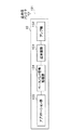
図18は、本実施の形態に係る基地局装置20が有するベースバンド信号処理部204の機能ブロック図であり、主にベースバンド信号処理部204における送信処理部の機能ブロックを示している。基地局装置20の配下となる移動端末装置10に対する送信データが上位局装置30から基地局装置20に対して転送される。
FIG. 18 is a functional block diagram of baseband
データ生成部301は、上位局装置30から転送された送信データをユーザ別にユーザデータとして出力する。コンポーネントキャリア選択部302は、移動端末装置10との無線通信に使用されるコンポーネントキャリアをユーザ毎に選択する。
The
図18には、コンポーネントキャリア数がM個(CC#1〜CC#M)の移動通信システム1に対応した基地局構成が例示されている。コンポーネントキャリアCC#1〜CC#Mには、結合コンポーネントキャリアで構成されるコンポーネントキャリアと、ノーマルコンポーネントキャリアのみで構成されるコンポーネントキャリアとが含まれる。たとえば、コンポーネントキャリアCC#1は、図2(B)に示すように、ノーマルコンポーネントキャリアの一端にキャリアセグメントが連結された結合コンポーネントキャリアである。
FIG. 18 illustrates a base station configuration corresponding to the
スケジューリング部300は、コンポーネントキャリアCC#1(結合コンポーネントキャリア)に関するリソース割り当てを制御しており、LTE端末ユーザとLTE−A端末ユーザとを区別してスケジューリングを行う。また、スケジューリング部300は、上り/下り共有制御チャネルのリソース割当てにおいてキャリアセグメントを考慮する。また、スケジューリン部300は、上位局装置30から送信データ及び再送指示が入力されると共に、上りリンクの信号を測定した受信部からチャネル推定値やリソースブロックのCQIが入力される。スケジューリング部300は、上位局装置30から入力された再送指示、チャネル推定値及びCQIを参照しながら、上下制御信号及び上下共有チャネル信号のスケジューリングを行う。移動通信における伝搬路は、周波数選択性フェージングにより周波数ごとに変動が異なる。そこで、ユーザ端末へのユーザデータ送信時に、各ユーザ端末に対してサブフレーム毎に通信品質の良好なリソースブロックを割り当てる適応周波数スケジューリングが適用される。適応周波数スケジューリングでは、各リソースブロックに対して伝搬路品質の良好なユーザ端末を選択して割り当てる。そのため、スケジューリング部300は、各ユーザ端末からフィードバックされるリソースブロック毎のCQIを用いてリソースブロックを割り当てる。また、割り当てたリソースブロックで所定のブロック誤り率を満たすMCS(符号化率、変調方式)を決定する。
The
基地局装置20のベースバンド信号処理部204は、データ生成部301から出力されるユーザデータ(一部の制御信号を含んでも良い)を伝送する共有データチャネル(PDSCH)をユーザ毎にチャネル符号化するチャネル符号化部303と、チャネル符号化されたユーザデータをユーザ毎に変調する変調部304と、変調されたユーザデータを無線リソースにマッピングするマッピング部305とを備えている。
The baseband
また、ベースバンド信号処理部204は、ユーザ固有の下り制御情報である下り共有データチャネル用制御情報を生成する下り制御情報生成部306と、ユーザ共通の下り制御情報である下り共通制御チャネル用制御情報を生成する下り共通チャネル用制御情報生成部307とを備えている。下り制御情報生成部306は、ユーザ毎に決定したリソース割り当て情報、MCS情報、HARQ用の情報、PUCCHの送信電力制御コマンド等から下りリンク制御信号(DCI)を生成する。このとき、下り制御情報生成部306は、LTE端末ユーザとLTE−A端末ユーザとを区別して制御情報を生成するが、下り共通チャネル用制御情報生成部307はノーマルコンポーネントキャリアのみで下り共通制御チャネル用制御情報を生成する。ベースバンド信号処理部204は、下り制御情報生成部306及び下り共通チャネル用制御情報生成部307で生成される制御情報をユーザ毎にチャネル符号化するチャネル符号化部308と、チャネル符号化された下り制御情報を変調する変調部309とを備えている。
Also, the baseband
また、ベースバンド信号処理部204は、上り共有データチャネル(PUSCH)を制御するための制御情報である上り共有データチャネル用制御情報をユーザ毎に生成する上り制御情報生成部311と、生成した上り共有データチャネル用制御情報をユーザ毎にチャネル符号化するチャネル符号化部312と、チャネル符号化した上り共有データチャネル用制御情報をユーザ毎に変調する変調部313とを備える。上り制御情報生成部311は、LTE端末ユーザとLTE−A端末ユーザとを区別して上り共有データチャネル用制御情報を生成する。
Further, the baseband
上記変調部309、313でユーザ毎に変調された制御情報は制御チャネル多重部314で多重され、さらにインタリーブ部315でインタリーブされる。インタリーブ部315から出力される制御信号及びマッピング部305から出力されるユーザデータは下りチャネル信号としてIFFT部316へ入力される。IFFT部316は、下りチャネル信号を逆高速フーリエ変換して周波数領域の信号から時系列の信号に変換する。サイクリックプレフィックス挿入部317は、下りチャネル信号の時系列信号にサイクリックプレフィックスを挿入する。なお、サイクリックプレフィクスは、マルチパス伝搬遅延の差を吸収するためのガードインターバルとして機能する。サイクリックプレフィックスが付加された送信データは、送受信部203に送出される。
The control information modulated for each user by the
図19は、移動端末装置10が有するベースバンド信号処理部104の機能ブロック図であり、LTE−AをサポートするLTE−A端末の機能ブロックを示している。
ベースバンド信号処理部104は、受信処理系の機能ブロックとして、CP除去部401、FFT部402、デマッピング部403、デインタリーブ部404、制御情報復調部405及びデータ復調部406を備えている。CP除去部401は、送受信部103で受信された受信信号からガードインターバルであるサイクリックプレフィックスを除去する。FFT部402は、サイクリックプレフィックスが除去された受信信号(OFDM信号)を高速フーリエ変換して時間成分の波形から周波数成分の直交マルチキャリア信号に変換する。デマッピング部403は、FFT部402で周波数領域に変換した受信信号を入力とし、対象となるデータ通信の通信帯域に含まれるサブキャリアだけを選択して、不要なサブキャリアを間引き処理し、受信信号の信号帯域受信信号として出力する。デインタリーブ部404は、送信側で施されたインタリーブと逆に並べ変えて制御情報及びユーザデータを元の順番に戻す。制御情報復調部405は、共通制御チャネル用制御情報を復調する共通制御チャネル用制御情報復調部405aと、上り共有データチャネル用制御情報を復調する上り共有データチャネル用制御情報復調部405bと、下り共有データチャネル用制御情報を復調する下り共有データチャネル用制御情報復調部405cとを備える。共通制御チャネル用制御情報復調部405aは、共通制御チャネル用制御情報についてはLTE端末及びLTE-A端末の双方で認識できるようにするため、LTE仕様(ノーマルコンポーネントキャリアに閉じた処理)にしたがって復調する。上り共有データチャネル用制御情報復調部405b及び下り共有データチャネル用制御情報復調部405cは、LTE-A用の制御情報を復調する。データ復調部406は、下り共有データチャネルであるPDSCHを復調する下り共有データ復調部406aと、下り共通チャネルデータである報知情報,ページング情報を復調する下り共通チャネルデータ復調部406bとを備えている。
FIG. 19 is a functional block diagram of the baseband
The baseband
また、ベースバンド信号処理部104は、送信処理系の機能ブロックとして、データ生成部411、チャネル符号化部412、変調部413、DFT部414、マッピング部415、IFFT部416、CP挿入部417を備えている。データ生成部411は、アプリケーション部105から入力されるビットデータから送信データを生成する。チャネル符号化部412は、送信データに対して誤り訂正等のチャネル符号化処理を施し、変調部413はチャネル符号化された送信データをQPSK等で変調する。DFT部414は、変調された送信データを離散フーリエ変換する。マッピング部415は、DFT後のデータシンボルの各周波数成分を、基地局装置に指示されたサブキャリア位置へマッピングする。すなわち、データシンボルの各周波数成分を、システム帯域に相当する帯域幅を持つIFFT部416のサブキャリア位置に入力し、他の周波数成分には0を設定する。IFFT部416は、システム帯域に相当する入力データを逆高速フーリエ変換して時系列データに変換し、CP挿入部417は時系列データに対してデータ区切りでサイクリックプレフィックスを挿入する。
The baseband
次に、基地局装置20での移動端末装置10に対するリソースブロック割当て及びRB割当てシグナリングについて説明する。連結コンポーネントキャリアであるコンポーネントキャリアCC#1が割当てられた移動端末装置10の1つをLTE−A端末UE#1、LTE端末UE#2として説明する。
Next, resource block allocation and RB allocation signaling for the mobile
基地局装置20において、コンポーネントキャリア選択部302がLTE−A端末UE#1及びLTE端末UE#2に対してコンポーネントキャリアCC#1を選択したものとする。スケジューリング部300は、LTE−A端末UE#1とLTE端末UE#2とを区別してスケジューリングする。LTE−A端末UE#1に対してはキャリアセグメントまで含めた連結コンポーネントキャリア全体を使ったリソース割り当てを行い、LTE端末UE#2に対してはキャリアセグメントを含まないノーマルコンポーネントキャリア部分だけを使ったリソース割り当てを行う。リソースブロックの割り当てについても、LTE−A端末UE#1とLTE端末UE#2とを区別して行う。
In the
スケジューリング部300は、LTE−A端末UE#1に対して、図6に示されるテーブルに基づいてコンポーネントキャリアCC#1のシステム帯域に対応したRBGサイズを決定する。同様に、LTE端末UE#2に対しても、図6に示されるテーブルに基づいてコンポーネントキャリアCC#1のシステム帯域に対応したRBGサイズを決定する。上記した通り、コンポーネントキャリアCC#1のうちLTE−A端末UE#1とLTE端末UE#2とで認識するシステム帯域は異なるが、同一のRBGサイズが選択される。
下り制御情報生成部306(UE#1)が、LTE−A端末UE#1に対するリソース割当て結果に基づいて、LTE−A端末UE#1に対するRB割当て情報を生成する。また、下り制御情報生成部306(UE#2)は、LTE端末UE#2に対するリソース割当て結果に基づいて、LTE端末UE#2に対するRB割当て情報を生成する。RB割当て情報はRBG単位で1つにまとめてシグナリングされる。
The downlink control information generation unit 306 (UE # 1) generates RB allocation information for the LTE-A
図6に示すテーブルは、ノーマルコンポーネントキャリア(NsRB数)と、当該ノーマルコンポーネントキャリア(RB数=Ns個)にキャリアセグメント(RB数=Ncs個)を結合した結合コンポーネントキャリア(RB数=Ns+Ncs)とで、RBGサイズが変化しないように、システム帯域(RB数)とRBGサイズとの対応関係が定められている。 The table shown in FIG. 6 includes normal component carriers (number of NsRBs), combined component carriers (number of RBs = Ns + Ncs) obtained by combining carrier segments (number of RBs = Ncs) with the normal component carriers (number of RBs = Ns). Thus, the correspondence between the system band (number of RBs) and the RBG size is determined so that the RBG size does not change.
このように、図6に示すテーブルに基づいてRBGサイズを決定することにより、ノーマルコンポーネントキャリアと結合コンポーネントキャリアとのRBGサイズを常に一致させることができ、RB割当てのオーバーへッド低減と複雑化の防止を図ることができる。 In this way, by determining the RBG size based on the table shown in FIG. 6, the RBG sizes of the normal component carrier and the combined component carrier can always be matched, and the RB allocation overhead is reduced and complicated. Can be prevented.
また、スケジューリング部300は、LTE端末とLTE−A端末とを区別してPDSCHの開始位置を制御する。図7に示すように、移動端末装置UE#1に対してPDSCHの開始位置が、キャリアセグメントの先頭RBとなるようにリソース割り当てを行い、LTE端末に対しては、PDSCHの開始位置がノーマルコンポーネントキャリアの先頭RBに揃えられ、かつキャリアセグメントにはPDCCHもPDSCHも割り当てられないように制御する。マッピング部305は、図7に示すようにPDSCHの開始位置をキャリアセグメントの先頭RBから順番にマッピングする。
In addition, the
または、図8に示すように、移動端末装置UE#1に対してPDCCHを送信している期間ではキャリアセグメントにおいて無送信とし(PDSCHを送らない)、キャリアセグメントのPDSCHの開始位置をノーマルコンポーネントキャリアにおけるPDSCHの開始位置と揃えるように制御する。マッピング部305は、図8に示すようにキャリアセグメントのPDSCHの開始位置がノーマルコンポーネントキャリアと揃えられるようにマッピングする。図7又は図8に示すようにマッピングされたPDSCHのRB割当て情報は下り制御情報生成部306で生成され、移動端末装置UE#1に対して送信される。
Alternatively, as shown in FIG. 8, in the period during which PDCCH is transmitted to mobile terminal
LTE端末に対しては、図7及び図8に示すようなキャリアセグメントへのPDSCHの割当ては行わないで、ノーマルコンポーネントキャリアに閉じてPDCCH及びPDSCHのリソース割り当てを行う。 For the LTE terminal, PDSCH allocation to the carrier segment as shown in FIG. 7 and FIG. 8 is not performed, but PDCCH and PDSCH resource allocation is performed by closing to the normal component carrier.
移動端末装置UE#1では、下り共有データチャネル用制御情報復調部405cがRB割当て情報を復調し、下り共有データ復調部406aがRB割当て情報にしたがってキャリアセグメントまで含めてPDSCHを復調する。
In the mobile terminal
また、スケジューリング部300は、LTE端末及びLTE−A端末に対するリソース割り当てにおいて、ユーザ共有サーチスペース及びユーザ固有サーチスペースはノーマルコンポーネントキャリアに割当てる。また、ユーザ共有サーチスペースのPDCCHサイズ(CCE数)は、ノーマルコンポーネントキャリア部分のサイズに基づいて計算し、ユーザ固有サーチスペースで割当て情報が通知される情報(PDSCH,PUSCH等のデータ)の割当てビット数(CCE数)はユーザ端末で対応可能なそれぞれのシステム帯域のサイズに基づいて計算する。
In addition, the
また、スケジューリング部300は、ディストリビューテッド送信の場合、図13に示すように、VRBを2分割して一方のPRBの第1スロットに割当て、もう一方を第2スロットに割当てるが、第1スロット又は第2スロットがキャリアセグメントのPRBに割り当てられることのないようにリソース割り当てする。すなわち、ノーマルコンポーネントキャリアでのみディストリビューテッド送信をサポートし、キャリアセグメントではディストリビューテッド送信しないように無線リソースを割り当てる。
In the case of distributed transmission, the
下り制御情報生成部306は、1ユーザ端末のみ受信する必要のある情報を伝送する制御チャネル(ユーザ個別PDCCH)で伝送される制御情報(PDSCH/PUSCH送信用制御情報)を、スケジューリング部300によるスケジューリング結果に基づいてユーザ毎に生成する。スケジューリング部300と同様にLTE端末とLTE−A端末とを区別して制御情報を生成する。スケジューリング部300においてLTE端末とLTE−A端末とを区別してユーザ固有サーチスペースのPDCCHサイズ(CCE数)が計算される。LTE端末はノーマルコンポーネントキャリア部分のみを対象としてCCE数を計算するが、LTE−A端末はキャリアセグメントまで含めた結合コンポーネントキャリア全体をシステム帯域の対象としてCCE数を決定する。下り制御情報生成部306は、上記の通り計算されたユーザ固有サーチスペースをノーマルコンポーネントキャリア部分に割当てたPDSCH/PUSCH送信用制御情報を生成する。
The downlink control
下り共通チャネル用制御情報生成部307は、同一セルに接続している全てのユーザ端末が同時に受信する必要のある情報を伝送する制御チャネル(ユーザ共通PDCCH)で伝送される制御情報(SIB/PCH/TPC送信用制御情報)を、スケジューリング部300によるスケジューリング結果に基づいてユーザ毎に生成する。スケジューリング部300においてLTE端末とLTE−A端末とを区別しないで、ユーザ共有サーチスペースのPDCCHサイズ(CCE数)が、ノーマルコンポーネントキャリア部分のサイズに基づいて計算する。下り共通チャネル用制御情報生成部307は、上記の通り計算されたユーザ共通サーチスペースをノーマルコンポーネントキャリア部分に割当てたSIB/PCH/TPC送信用制御情報を生成する。
The downlink common channel control
上り制御情報生成部311は、ユーザ毎に上り共有データチャネル用制御情報を生成する。スケジューリング部300においてLTE端末とLTE−A端末とを区別して上り共有データチャネルのリソース割当てをしている。このとき、スケジューリング部300はLTE−A端末に対しては、図14に示すようにキャリアセグメントにもPUSCHを割り当てるが、LTE端末に対してはノーマルコンポーネントキャリア部分のみにPUSCHを割り当てる。上り制御情報生成部311は、上り共有データチャネルのリソース割当て結果を受け、LTE端末とLTE−A端末とを区別してユーザ個別の共有データチャネル用制御情報を生成する。
The uplink control
以上のようにリソース割り当てされたユーザ個別PDCCH及びユーザ共通PDCCHが制御チャネル多重されて送信される。 The user dedicated PDCCH and the user common PDCCH to which resources are allocated as described above are transmitted after being subjected to control channel multiplexing.
LTE−A端末UE#1では、共通制御チャネル用制御情報復調部405aがユーザ共有サーチスペースをブラインドデコーディングしてユーザ共通PDCCHを復調し、SIB/PCH/TPC送信用制御情報を取得する。また、下り共有データチャネル用制御情報復調部405cがユーザ個別サーチスペースをブラインドデコーディングしてユーザ個別PDCCHを復調し、PDSCH/PUSCH送信用制御情報を取得する。下り共有データ復調部406aがPDSCH/PUSCH送信用制御情報に示されるRB割当て情報にしたがってキャリアセグメントまで含めてPDSCHを復調する。さらに、上り共有データチャネル用制御情報復調部405bがユーザ個別PDCCHを復調し、上り共有データチャネル用制御情報を取得する。マッピング部415は、共通制御チャネル用制御情報(例えば報知情報,ページング情報)と上り共有データチャネル用制御情報とを用いて上りリンク制御情報(PUCCH)及び上り共有データチャネル(PUSCH)の各周波数成分をマッピングする。図14(A)に示すように、上り共有データチャネル用にキャリアセグメントがリソース割り当てされている場合は、PUSCHをキャリアセグメント領域にマッピングする。また、LTE−A端末においてもPUCCHはノーマルコンポーネントキャリアの両端に割り当てられ、サブフレーム内周波数ホッピングさせて送られる。また、図14(B)に示すように、ノーマルコンポーネントキャリアでのみPUSCHをサブフレーム内周波数ホッピングし、キャリアセグメントをホッピング先にしないようにマッピングする。
In the LTE-A
以上、上述の実施形態を用いて本発明について詳細に説明したが、当業者にとっては、本発明が本明細書中に説明した実施形態に限定されるものではないということは明らかである。本発明は、特許請求の範囲の記載により定まる本発明の趣旨及び範囲を逸脱することなく修正及び変更態様として実施することができる。従って、本明細書の記載は、例示説明を目的とするものであり、本発明に対して何ら制限的な意味を有するものではない。 Although the present invention has been described in detail using the above-described embodiments, it is obvious to those skilled in the art that the present invention is not limited to the embodiments described in this specification. The present invention can be implemented as modified and changed modes without departing from the spirit and scope of the present invention defined by the description of the scope of claims. Therefore, the description of the present specification is for illustrative purposes and does not have any limiting meaning to the present invention.
1 移動通信システム
10 移動端末装置
20 基地局装置
30 上位局装置
40 コアネットワーク
101 送受信アンテナ
102 アンプ部
103 送受信部
104 ベースバンド信号処理部
105 アプリケーション部
201 送受信アンテナ
202 アンプ部
203 送受信部
204 ベースバンド信号処理部
205 呼処理部
206 伝送路インターフェース
300 スケジューリング部
301 データ生成部
302 コンポーネントキャリア選択部
303、308、312 チャネル符号化部
304、309、313 変調部
305 マッピング部
306 下り制御情報生成部
307 下り共通チャネル用制御情報生成部
311 上り制御情報生成部
DESCRIPTION OF
Claims (2)
前記ユーザ端末が前記基本周波数ブロックまで対応可能な第1仕様の端末であれば前記基本周波数ブロックのみを用い前記第1仕様に基づいて通信し、前記ユーザ端末が前記結合周波数ブロックまで対応可能な第2仕様の端末であれば前記結合周波数ブロックを用い前記第2仕様に基づいて通信できるようにリソース割当てするリソース割当て手段と、
前記リソース割当て手段によるリソース割当てにしたがって前記ユーザ端末との無線通信する通信手段と、
を具備し、
前記リソース割当て手段は、無線リソースの最小割当て単位であるリソースブロックのシグナリング単位となるRBG(Resource Block Group)サイズを予め用意されたテーブルにしたがって決定し、前記テーブルが複数のシステム帯域に対応してRBGサイズが段階的に定義されており、前記基本周波数ブロックと前記結合周波数ブロックとでRBGサイズが同一となるように定められていることを特徴とする基地局装置。 A basic frequency block corresponding to an existing system band and a combined frequency block formed by combining an additional carrier with the existing system band are arranged on the frequency axis, and the basic frequency block or the combined frequency block is connected to a user terminal. Selection means for selecting for wireless communication;
If the user terminal is a terminal of the first specification capable of supporting up to the fundamental frequency block, communication is performed based on the first specification using only the fundamental frequency block, and the user terminal is capable of supporting up to the combined frequency block. and resource allocation means you allocated resources to communicate on the basis of the second specification using the combined frequency block if terminal 2 specifications,
Communication means for wirelessly communicating with the user terminal according to resource allocation by the resource allocation means;
Equipped with,
The resource allocation means determines an RBG (Resource Block Group) size that is a signaling unit of a resource block, which is a minimum allocation unit of radio resources, according to a table prepared in advance, and the table corresponds to a plurality of system bands. An RBG size is defined in a stepwise manner, and the base station apparatus is characterized in that the RBG size is determined to be the same in the basic frequency block and the combined frequency block .
前記ユーザ端末が前記基本周波数ブロックまで対応可能な第1仕様の端末であれば前記基本周波数ブロックのみを用い前記第1仕様に基づいて通信し、前記ユーザ端末が前記結合周波数ブロックまで対応可能な第2仕様の端末であれば前記結合周波数ブロックを用い前記第2仕様に基づいて通信できるようにリソース割当てする工程と、
前記リソース割当てによるリソース割当てにしたがって前記ユーザ端末との無線通信する工程と、を具備し、
前記リソース割当てする工程において、無線リソースの最小割当て単位であるリソースブロックのシグナリング単位となるRBG(Resource Block Group)サイズを予め用意されたテーブルにしたがって決定し、前記テーブルが複数のシステム帯域に対応してRBGサイズが段階的に定義されており、前記基本周波数ブロックと前記結合周波数ブロックとでRBGサイズが同一となるように定められていることを特徴とする無線通信制御方法。 A basic frequency block corresponding to an existing system band and a combined frequency block formed by combining an additional carrier with the existing system band are arranged on the frequency axis, and the basic frequency block or the combined frequency block is connected to a user terminal. Selecting for wireless communication; and
If the user terminal is a terminal of the first specification capable of supporting up to the fundamental frequency block, communication is performed based on the first specification using only the fundamental frequency block, and the user terminal is capable of supporting up to the combined frequency block. Assigning resources so that communication can be performed based on the second specification using the combined frequency block if the terminal has two specifications;
Wirelessly communicating with the user terminal according to the resource allocation by the resource allocation ,
In the step of allocating resources, an RBG (Resource Block Group) size that is a signaling unit of a resource block that is a minimum allocation unit of radio resources is determined according to a previously prepared table, and the table corresponds to a plurality of system bands. The RBG size is defined stepwise, and the RBG size is determined to be the same in the basic frequency block and the combined frequency block .
Priority Applications (4)
| Application Number | Priority Date | Filing Date | Title |
|---|---|---|---|
| JP2010003494A JP5108902B2 (en) | 2010-01-11 | 2010-01-11 | Base station apparatus and radio communication control method |
| US13/521,229 US9137803B2 (en) | 2010-01-11 | 2010-12-06 | Radio communication control method, base station apparatus and mobile terminal apparatus |
| EP20100842163 EP2525615A1 (en) | 2010-01-11 | 2010-12-06 | Wireless communication control method, base station device, and mobile terminal device |
| PCT/JP2010/071839 WO2011083650A1 (en) | 2010-01-11 | 2010-12-06 | Wireless communication control method, base station device, and mobile terminal device |
Applications Claiming Priority (1)
| Application Number | Priority Date | Filing Date | Title |
|---|---|---|---|
| JP2010003494A JP5108902B2 (en) | 2010-01-11 | 2010-01-11 | Base station apparatus and radio communication control method |
Publications (2)
| Publication Number | Publication Date |
|---|---|
| JP2011142598A JP2011142598A (en) | 2011-07-21 |
| JP5108902B2 true JP5108902B2 (en) | 2012-12-26 |
Family
ID=44305388
Family Applications (1)
| Application Number | Title | Priority Date | Filing Date |
|---|---|---|---|
| JP2010003494A Expired - Fee Related JP5108902B2 (en) | 2010-01-11 | 2010-01-11 | Base station apparatus and radio communication control method |
Country Status (4)
| Country | Link |
|---|---|
| US (1) | US9137803B2 (en) |
| EP (1) | EP2525615A1 (en) |
| JP (1) | JP5108902B2 (en) |
| WO (1) | WO2011083650A1 (en) |
Families Citing this family (16)
| Publication number | Priority date | Publication date | Assignee | Title |
|---|---|---|---|---|
| KR101600655B1 (en) * | 2009-06-16 | 2016-03-07 | 샤프 가부시키가이샤 | Mobile station apparatus, base station apparatus, radio communication method and integrated circuit |
| JP5285629B2 (en) * | 2010-01-11 | 2013-09-11 | 株式会社エヌ・ティ・ティ・ドコモ | Base station apparatus, mobile station apparatus, and control information transmission method |
| US20140044085A1 (en) * | 2011-05-02 | 2014-02-13 | Pantech Co., Ltd | Apparatus and method for transmitting resource allocation information |
| CN103733560B (en) * | 2011-08-12 | 2017-08-11 | 交互数字专利控股公司 | Downlink resource allocation for flexible bandwidth operation in wireless systems |
| CN103650596A (en) * | 2011-09-29 | 2014-03-19 | 富士通株式会社 | Downlink control information transmission method and blind detection method, base station and terminal equipment |
| US9462622B2 (en) * | 2011-11-18 | 2016-10-04 | Lg Electronics Inc. | Method for requesting device-to-device communication in wireless access system and apparatus for same |
| CN104205990B (en) * | 2013-01-30 | 2018-11-06 | 华为技术有限公司 | A method for implementing radio resource control protocol functions, a macro base station, and a micro cell node |
| KR101739214B1 (en) | 2013-01-30 | 2017-05-23 | 후아웨이 테크놀러지 컴퍼니 리미티드 | Data scheduling method and apparatus |
| US10448351B2 (en) * | 2013-04-02 | 2019-10-15 | Qualcomm Incorporated | Employing neighboring cell assistance information for interference mitigation |
| CN104349491A (en) * | 2013-08-08 | 2015-02-11 | 中兴通讯股份有限公司 | PESCH (physical downlink shared channel) transmission method, system and network side equipment |
| KR102149630B1 (en) * | 2016-11-05 | 2020-08-28 | 애플 인크. | Asymmetric bandwidth support and dynamic bandwidth adjustment |
| JP7313513B2 (en) * | 2017-01-06 | 2023-07-24 | パナソニック インテレクチュアル プロパティ コーポレーション オブ アメリカ | Terminal, communication method and integrated circuit |
| EP3566513B1 (en) | 2017-01-06 | 2022-08-10 | Panasonic Intellectual Property Corporation of America | Base station, terminal, and communication method |
| US11601820B2 (en) | 2017-01-27 | 2023-03-07 | Qualcomm Incorporated | Broadcast control channel for shared spectrum |
| WO2019148499A1 (en) | 2018-02-05 | 2019-08-08 | Nec Corporation | Methods and devices of resource mapping for data transmission and of data receiving |
| US11424851B2 (en) * | 2020-12-09 | 2022-08-23 | Qualcomm Incorporated | Dynamic bit width determination for resource block group mask |
Family Cites Families (5)
| Publication number | Priority date | Publication date | Assignee | Title |
|---|---|---|---|---|
| EP3528419B1 (en) * | 2008-06-19 | 2021-09-22 | Huawei Technologies Co., Ltd. | Carrier aggregation |
| CN102067661B (en) * | 2008-06-20 | 2016-08-17 | 日本电气株式会社 | Resource allocation methods, recognition methods, base station, movement station and program |
| US20110081913A1 (en) * | 2009-10-02 | 2011-04-07 | Lee Jung A | Method of bandwidth extension by aggregating backwards compatible and non-backwards compatible carriers |
| US8897241B2 (en) * | 2009-10-14 | 2014-11-25 | Lg Electronics Inc. | Radio resource allocation |
| US9559829B2 (en) * | 2009-11-04 | 2017-01-31 | Telefonaktiebolaget Lm Ericsson (Publ) | Signaling for flexible carrier aggregation |
-
2010
- 2010-01-11 JP JP2010003494A patent/JP5108902B2/en not_active Expired - Fee Related
- 2010-12-06 US US13/521,229 patent/US9137803B2/en not_active Expired - Fee Related
- 2010-12-06 WO PCT/JP2010/071839 patent/WO2011083650A1/en not_active Ceased
- 2010-12-06 EP EP20100842163 patent/EP2525615A1/en not_active Withdrawn
Also Published As
| Publication number | Publication date |
|---|---|
| WO2011083650A1 (en) | 2011-07-14 |
| US9137803B2 (en) | 2015-09-15 |
| US20130070692A1 (en) | 2013-03-21 |
| EP2525615A1 (en) | 2012-11-21 |
| JP2011142598A (en) | 2011-07-21 |
Similar Documents
| Publication | Publication Date | Title |
|---|---|---|
| JP5108902B2 (en) | Base station apparatus and radio communication control method | |
| JP5072999B2 (en) | Wireless communication control device and wireless communication control method | |
| JP5698126B2 (en) | Mobile communication system, base station apparatus, mobile station apparatus, and mobile communication method | |
| US8982817B2 (en) | Radio communication system, base station apparatus and user terminal | |
| JP5462085B2 (en) | Base station apparatus and communication control method | |
| JP5097793B2 (en) | Base station apparatus, mobile terminal apparatus and communication control method | |
| WO2012150666A1 (en) | User terminal, wireless base station device, wireless communication system, and wireless communication method | |
| JP5801694B2 (en) | Radio communication system, radio base station apparatus, user terminal, and radio communication method | |
| EP2916598A1 (en) | User terminal, wireless communication system, and wireless communication method | |
| JP5809532B2 (en) | Radio communication system, radio base station apparatus, user terminal, and radio communication method | |
| JP2011041226A (en) | Method for controlling wireless communication, radio base station apparatus, and mobile terminal device | |
| JP5298086B2 (en) | Base station apparatus, mobile terminal apparatus and communication control method | |
| JP5137992B2 (en) | Base station apparatus, mobile terminal apparatus and communication control method | |
| US9077532B2 (en) | User terminal and base station apparatus | |
| JPWO2010073477A1 (en) | Mobile communication system, base station apparatus, mobile station apparatus, and mobile communication method | |
| JP5280573B2 (en) | Wireless communication system, communication control method, base station apparatus and mobile terminal apparatus |
Legal Events
| Date | Code | Title | Description |
|---|---|---|---|
| A621 | Written request for application examination |
Free format text: JAPANESE INTERMEDIATE CODE: A621 Effective date: 20110830 |
|
| A131 | Notification of reasons for refusal |
Free format text: JAPANESE INTERMEDIATE CODE: A131 Effective date: 20120731 |
|
| A521 | Request for written amendment filed |
Free format text: JAPANESE INTERMEDIATE CODE: A523 Effective date: 20120820 |
|
| TRDD | Decision of grant or rejection written | ||
| A01 | Written decision to grant a patent or to grant a registration (utility model) |
Free format text: JAPANESE INTERMEDIATE CODE: A01 Effective date: 20120911 |
|
| A01 | Written decision to grant a patent or to grant a registration (utility model) |
Free format text: JAPANESE INTERMEDIATE CODE: A01 |
|
| A61 | First payment of annual fees (during grant procedure) |
Free format text: JAPANESE INTERMEDIATE CODE: A61 Effective date: 20121005 |
|
| R150 | Certificate of patent or registration of utility model |
Free format text: JAPANESE INTERMEDIATE CODE: R150 |
|
| FPAY | Renewal fee payment (event date is renewal date of database) |
Free format text: PAYMENT UNTIL: 20151012 Year of fee payment: 3 |
|
| R250 | Receipt of annual fees |
Free format text: JAPANESE INTERMEDIATE CODE: R250 |
|
| R250 | Receipt of annual fees |
Free format text: JAPANESE INTERMEDIATE CODE: R250 |
|
| R250 | Receipt of annual fees |
Free format text: JAPANESE INTERMEDIATE CODE: R250 |
|
| LAPS | Cancellation because of no payment of annual fees |