WO2009113827A2 - 충돌 상황에 따라 명령을 재전송하는 rfid 리더 장치 및 그 제어방법 - Google Patents
충돌 상황에 따라 명령을 재전송하는 rfid 리더 장치 및 그 제어방법 Download PDFInfo
- Publication number
- WO2009113827A2 WO2009113827A2 PCT/KR2009/001255 KR2009001255W WO2009113827A2 WO 2009113827 A2 WO2009113827 A2 WO 2009113827A2 KR 2009001255 W KR2009001255 W KR 2009001255W WO 2009113827 A2 WO2009113827 A2 WO 2009113827A2
- Authority
- WO
- WIPO (PCT)
- Prior art keywords
- collision
- tag
- command
- reader
- unit
- Prior art date
Links
- 238000000034 method Methods 0.000 title claims abstract description 105
- 238000003745 diagnosis Methods 0.000 claims abstract description 126
- 238000004891 communication Methods 0.000 claims abstract description 34
- 238000004458 analytical method Methods 0.000 claims abstract description 5
- 230000004044 response Effects 0.000 claims description 90
- 230000005540 biological transmission Effects 0.000 claims description 23
- 238000004364 calculation method Methods 0.000 claims description 10
- 230000001934 delay Effects 0.000 claims 1
- 238000001514 detection method Methods 0.000 description 76
- 230000008569 process Effects 0.000 description 42
- 230000003111 delayed effect Effects 0.000 description 12
- 230000008859 change Effects 0.000 description 8
- 238000010586 diagram Methods 0.000 description 8
- 230000007246 mechanism Effects 0.000 description 5
- 238000005516 engineering process Methods 0.000 description 4
- 230000006870 function Effects 0.000 description 4
- 230000003068 static effect Effects 0.000 description 4
- 230000003044 adaptive effect Effects 0.000 description 3
- 230000008901 benefit Effects 0.000 description 3
- 230000000694 effects Effects 0.000 description 3
- 125000004122 cyclic group Chemical group 0.000 description 2
- 238000013461 design Methods 0.000 description 2
- 238000011161 development Methods 0.000 description 2
- 238000012986 modification Methods 0.000 description 2
- 230000004048 modification Effects 0.000 description 2
- 238000012545 processing Methods 0.000 description 2
- 230000033228 biological regulation Effects 0.000 description 1
- 230000003247 decreasing effect Effects 0.000 description 1
- 230000002093 peripheral effect Effects 0.000 description 1
- 230000000306 recurrent effect Effects 0.000 description 1
- 238000011160 research Methods 0.000 description 1
- 238000012827 research and development Methods 0.000 description 1
- 230000000630 rising effect Effects 0.000 description 1
- 230000035945 sensitivity Effects 0.000 description 1
- 230000001360 synchronised effect Effects 0.000 description 1
- 230000002123 temporal effect Effects 0.000 description 1
- 230000007704 transition Effects 0.000 description 1
- 230000001960 triggered effect Effects 0.000 description 1
Images


Classifications
-
- G—PHYSICS
- G06—COMPUTING; CALCULATING OR COUNTING
- G06K—GRAPHICAL DATA READING; PRESENTATION OF DATA; RECORD CARRIERS; HANDLING RECORD CARRIERS
- G06K7/00—Methods or arrangements for sensing record carriers, e.g. for reading patterns
- G06K7/0008—General problems related to the reading of electronic memory record carriers, independent of its reading method, e.g. power transfer
-
- H—ELECTRICITY
- H04—ELECTRIC COMMUNICATION TECHNIQUE
- H04L—TRANSMISSION OF DIGITAL INFORMATION, e.g. TELEGRAPHIC COMMUNICATION
- H04L1/00—Arrangements for detecting or preventing errors in the information received
- H04L1/12—Arrangements for detecting or preventing errors in the information received by using return channel
- H04L1/16—Arrangements for detecting or preventing errors in the information received by using return channel in which the return channel carries supervisory signals, e.g. repetition request signals
- H04L1/18—Automatic repetition systems, e.g. Van Duuren systems
-
- G—PHYSICS
- G06—COMPUTING; CALCULATING OR COUNTING
- G06K—GRAPHICAL DATA READING; PRESENTATION OF DATA; RECORD CARRIERS; HANDLING RECORD CARRIERS
- G06K7/00—Methods or arrangements for sensing record carriers, e.g. for reading patterns
- G06K7/10—Methods or arrangements for sensing record carriers, e.g. for reading patterns by electromagnetic radiation, e.g. optical sensing; by corpuscular radiation
- G06K7/10009—Methods or arrangements for sensing record carriers, e.g. for reading patterns by electromagnetic radiation, e.g. optical sensing; by corpuscular radiation sensing by radiation using wavelengths larger than 0.1 mm, e.g. radio-waves or microwaves
- G06K7/10019—Methods or arrangements for sensing record carriers, e.g. for reading patterns by electromagnetic radiation, e.g. optical sensing; by corpuscular radiation sensing by radiation using wavelengths larger than 0.1 mm, e.g. radio-waves or microwaves resolving collision on the communication channels between simultaneously or concurrently interrogated record carriers.
- G06K7/10029—Methods or arrangements for sensing record carriers, e.g. for reading patterns by electromagnetic radiation, e.g. optical sensing; by corpuscular radiation sensing by radiation using wavelengths larger than 0.1 mm, e.g. radio-waves or microwaves resolving collision on the communication channels between simultaneously or concurrently interrogated record carriers. the collision being resolved in the time domain, e.g. using binary tree search or RFID responses allocated to a random time slot
-
- G—PHYSICS
- G06—COMPUTING; CALCULATING OR COUNTING
- G06K—GRAPHICAL DATA READING; PRESENTATION OF DATA; RECORD CARRIERS; HANDLING RECORD CARRIERS
- G06K7/00—Methods or arrangements for sensing record carriers, e.g. for reading patterns
- G06K7/10—Methods or arrangements for sensing record carriers, e.g. for reading patterns by electromagnetic radiation, e.g. optical sensing; by corpuscular radiation
- G06K7/10009—Methods or arrangements for sensing record carriers, e.g. for reading patterns by electromagnetic radiation, e.g. optical sensing; by corpuscular radiation sensing by radiation using wavelengths larger than 0.1 mm, e.g. radio-waves or microwaves
- G06K7/10316—Methods or arrangements for sensing record carriers, e.g. for reading patterns by electromagnetic radiation, e.g. optical sensing; by corpuscular radiation sensing by radiation using wavelengths larger than 0.1 mm, e.g. radio-waves or microwaves using at least one antenna particularly designed for interrogating the wireless record carriers
- G06K7/10356—Methods or arrangements for sensing record carriers, e.g. for reading patterns by electromagnetic radiation, e.g. optical sensing; by corpuscular radiation sensing by radiation using wavelengths larger than 0.1 mm, e.g. radio-waves or microwaves using at least one antenna particularly designed for interrogating the wireless record carriers using a plurality of antennas, e.g. configurations including means to resolve interference between the plurality of antennas
-
- H—ELECTRICITY
- H04—ELECTRIC COMMUNICATION TECHNIQUE
- H04B—TRANSMISSION
- H04B5/00—Near-field transmission systems, e.g. inductive or capacitive transmission systems
- H04B5/40—Near-field transmission systems, e.g. inductive or capacitive transmission systems characterised by components specially adapted for near-field transmission
- H04B5/48—Transceivers
Definitions
- the present invention relates to a mobile RFID reader device and a control method thereof, and more particularly, to an RFID reader device and a control method thereof capable of performing command retransmission according to a situation according to the type of collision and adaptively setting a waiting time for command retransmission. It is about.
- the present invention is derived from the research conducted as part of the IT source technology development project of the Ministry of Knowledge Economy and the Ministry of Information and Telecommunication Research and Development. [Task management number: 2008-F-052-01, Task name: Next-generation RFID for individual item unit application] Technology development].
- LBT Listen Before Talk
- TDM time division multiplexing
- FDM frequency division multiplexing
- the RFID reader In order to effectively use an RFID reader in a mobile environment, the RFID reader must be adaptive to a communication error that is recently emerging in a mobile environment.
- a general RFID air interface specification such as ISO / IEC 18000-6 Type C shows that the timing of the command that can be retransmitted by the reader or the condition of retransmitting the command when a failure occurs during the inventory round. No regulation is in place.
- the present invention is to solve the above-mentioned problems of the prior art, and in particular, in a mobile RFID environment, an RFID reader capable of performing command retransmission according to various collision types and situations and adaptively setting an optimal waiting time for command retransmission. And a control method thereof.
- an RFID reader device for retransmitting a command according to a collision situation includes a received signal received during a set reception time corresponding to a transmission signal from an RF communication unit capable of transmitting and receiving a signal with one or more tags. Based on a collision diagnosis unit for checking a collision occurrence of a received signal and diagnosing a collision type according to the analysis result of the received signal data, and a collision occurrence and collision type received from the collision diagnosis unit.
- a conflict resolution unit for retransmitting the command to the tag through the RF communication unit according to a collision situation, the conflict resolution unit including a situational command retransmission unit for determining whether to retransmit the command based on whether a collision has occurred and the collision type; It includes a random waiting time calculation unit for calculating a random waiting time for retransmission of the command.
- the control method of the RFID reader device having a collision diagnosis unit and a conflict resolution unit according to the present invention and retransmitting a command according to a collision situation
- the collision diagnosis unit is received during the set reception time corresponding to the transmission signal from the RF communication unit
- the collision diagnosis step of analyzing the data of the received signal, checking whether the received signal has occurred, and diagnosing the collision type according to the analysis result of the received signal data, and the collision solver is based on the collision and the collision type.
- a conflict resolution step for resending the command to the tag through the RF communication unit according to the situation, and the conflict resolution step includes a situation-specific command retransmission step of determining whether to resend the command based on whether a collision has occurred and the collision type.
- a random waiting time calculating step of calculating a random waiting time for retransmission of the command.
- the cause of the collision can be quickly recognized. Therefore, the cause of the collision can be dealt with.
- a collision is detected in a mobile application having an RFID reader, by processing a collision control according to a situation corresponding to the collision type, an inventory round that has already started can be successfully completed.
- command retransmission can be performed according to the situation, and a waiting time for command retransmission can be adaptively set.
- 1 to 3 are exemplary views showing a collision type situation according to the present invention.
- FIG. 4 is a block diagram illustrating a configuration of an RFID reader according to the present invention.
- 5 to 11 are exemplary views referred to to explain the operation of the RFID reader according to the present invention.
- 15 is a flowchart illustrating a procedure of retransmitting a command for each collision situation according to an embodiment of the present invention.
- 16 is a pseudo code representation of a conflict resolution algorithm described with reference to FIG. 15;
- 17 to 19 are exemplary timing diagrams for describing a conflict resolution method according to each collision situation according to an embodiment of the present invention.
- 20 is a timing diagram illustrating the meaning of a minimum retransmission wait time according to an embodiment of the present invention
- 21 is a timing diagram illustrating the meaning of a maximum retransmission wait time according to an embodiment of the present invention.
- 23 is a flowchart illustrating a procedure of dynamically changing a wait time parameter c according to a current collision rate
- 24 is a flowchart illustrating a procedure of dynamically changing the wait time parameter c according to the current collision rate and timeout rate.
- a mobile RFID service for inquiring or purchasing information on a tagged product or a work with a mobile phone equipped with an RFID interrogator operating in an RFID environment of an ultrahigh frequency (UHF) band includes: When an error occurs in a received signal due to a collision between a reader and a nearby RFID reader or a nearby tag, in order to resolve the conflict, the received signal is analyzed to identify the cause of the collision, and commands are issued according to the situation of the collision.
- the present invention provides an apparatus and a method for retransmission and appropriately setting a waiting time for retransmission.
- the present invention relates to an air interface specification of mobile radio frequency identification (RFID), and the system according to the present invention is an interrogator talks first (ITF) system that operates in a passive backscatter manner.
- RFID mobile radio frequency identification
- ITF interrogator talks first
- the RFID reader according to the present invention does not need to support channel sensing. For example, there is no need to implement List Before Talk (LBT), but at the risk of conflict between the readers and send commands. In addition, it is not necessary to synchronize between readers using a control channel for time division multiplexing (TDM).
- LBT List Before Talk
- TDM time division multiplexing
- the tag is powered by an RF signal provided by the reader and modulates the reflection coefficient of the antenna to backscatter the data to the reader to respond to commands from the reader. It is assumed that the operation of the tag is a passive mode and does not actively initiate any RF communication.
- FIELD OF THE INVENTION The present invention relates to collision arbitration and collision avoidance in mobile RFID applications, and to a mechanism that can be used to mitigate the effects of collisions and avoid subsequent conflicts.
- 1 to 3 illustrate a network collision situation according to an embodiment of the present invention.
- a tag on tag collision which is a collision occurring between a plurality of tags
- a multi reader to tag collision which is a collision occurring between a plurality of RFID readers and tags
- Interrogator to Tag Collision a collision that occurs between a corresponding RFID reader and one or more nearby RFID readers.
- FIG. 1 illustrates a tag to tag collision situation according to an embodiment of the present invention.
- a 'tag to tag collision' situation occurs when a plurality of tags 200 are provided in A, a read range of one RFID reader R 100.
- tags 200a and T2 200b are provided as an example.
- the present disclosure is not limited thereto.
- T1 200a and T2 200b located in A respond to the inventory command of R 100.
- the T1 200a and the T2 200b simultaneously respond, the parallel response by the T1 200a and the T2 200b interferes with the response of the counterpart tag. This is the 'tag to tag collision'.
- tag collision adjustment means a conventional algorithm for resolving tag-to-tag collision unless otherwise described.
- FIG. 2 illustrates a multi-reader-to-tag collision situation according to an embodiment of the present invention.
- a 'multi-reader to tag collision' situation is generated by a plurality of RFID readers.
- two RFID readers, R1 (100a) and R2 (100b), are provided as an example, but the present invention is not limited thereto.
- the inventory command output from the R1 100a and the R2 100b may collide in the T 200.
- an error occurs when the T 200 decodes the inventory command received from the R1 100a and the R2 100b, respectively.
- FIG. 3 illustrates a leader-to-leader collision situation according to an embodiment of the present invention.
- 'leader to reader collision' includes two RFID readers, R1 (100a) and R2 (100b), and B2, which is an interference range of R2 (100b), is R1 (100a). It occurs when it overlaps with A1 which is reading range of.
- R1 (100a) and R2 (100b) are provided in the embodiment of FIG. 3, but the present invention is not limited thereto.
- the 'reader-to-reader collision' may occur even in a situation where the read ranges of R1 (100a) and R2 (100b) do not overlap.
- the T 200 transmits a response signal to the inventory command of the R1 100a to the R1 100a. Accordingly, R1 100a performs an operation corresponding to the response signal received from T 200.
- a predetermined command or other signal output from R2 (100b) and the response signal of T (200) input to R1 (100a) collide with each other. This is the 'leader vs. leader conflict'.
- FIG. 4 is a diagram referred to explain the configuration of an RFID reader according to an embodiment of the present invention.
- the RFID reader includes a reader controller 110, a reader transmitter 120, an RF communicator 130, a reader receiver 140, a collision controller 160, and a timer 150. .
- the reader controller 110 outputs an inventory command to at least one tag located within a predetermined range, and processes the received tag response in response to the inventory command.
- the reader transmitter 120 (modem transmitter) transmits an inventory command of the reader controller 110 to the RF communicator 130.
- the reader transmitter 120 modulates the inventory command output from the reader controller 110 and transmits the inventory command to the RF communicator 130.
- the RF communication unit 130 receives the inventory command of the reader controller 110 from the reader transmitter 120 and transmits the inventory command to at least one tag located within a predetermined range. In addition, the RF communication unit 130 transmits an inventory command to the outside, and receives a signal from the outside for a set reception time. At this time, the RF communication unit 130 receives a tag response from a tag within a read range in response to the inventory command already sent during the set reception time. Of course, the RF communication unit 130 may receive a signal from another RFID reader or noise that does not include any signal in addition to the tag response. In this case, the RF communication unit 130 transmits the received signal to the reader receiver 140.
- the reader receiver 140 (modem receiver) transmits a signal received from the RF communicator 130 to the reader controller 110 and the collision controller 160. In this case, the reader receiver 140 transmits the received signal data to the collision controller 160.
- the reader receiver 140 includes a decoder (not shown). At this time, the decoder decodes the received signal from the RF communication unit 130 and detects a valid preamble from the decoded received signal. The reader receiver 140 outputs a valid preamble detection signal (VPD) to the collision controller 160 according to a valid preamble detection result of the decoder.
- VPD valid preamble detection signal
- the decoder also detects a cyclic redundancy check (CRC) error from the decoded received signal.
- CRC cyclic redundancy check
- the reader receiver 140 outputs the CRC error detection signal to the collision controller 160 according to the CRC error detection result of the decoder.
- the collision controller 160 includes a collision diagnosis unit 161 and a collision resolution unit 165.
- the collision diagnosis unit 161 analyzes the received signal data input from the reader receiver 140 to determine whether a collision occurs with respect to the received signal, and diagnoses the collision type according to the analysis result of the received signal data.
- the collision diagnosis unit 161 includes a valid bit detection (VBD) module 163 which is a valid bit detection module.
- the VBD module 163 is a submodule of the collision diagnosis unit 161 and detects a valid bit from a received signal input from the reader receiver 140. In other words, the VBD module 163 detects a valid logical signal by detecting a rising edge and a falling edge of the received signal, that is, a modulated subcarrier within a tolerance of the air interface specification. At this time, the VBD module 163 outputs a valid bit detection signal according to the valid bit detection result.
- the collision diagnosis unit 161 determines that the valid bit detection signal VBD is positive. In other words, when the valid bit detection signal is detected, the collision diagnosis unit 161 determines that the valid bit is detected from the VBD module 163.
- the collision diagnosis unit 161 determines that the valid bit detection signal VBD is negative. In other words, when the valid bit detection signal is detected, the collision diagnosis unit 161 determines that the valid bit is not detected from the VBD module 163.
- the collision diagnosis unit 161 determines whether a tag response signal corresponding to the transmission signal exists based on the valid bit detection signal output from the VBD module 163. As a result, the collision diagnosis unit 161 determines whether the received signal is a tag response corresponding to the transmission signal or a signal that does not contain any signal.
- the collision diagnosis unit 161 further includes an interrogator collision detection (ICD) module 162 which is a reader collision detection module that detects a collision of an RFID reader.
- ICD interrogator collision detection
- the ICD module 162 is a submodule of the collision diagnosis unit 161.
- the ICD module 162 analyzes the received signal data input from the reader receiver 140 and calculates an average value of the received signal data.
- the ICD module 162 detects a collision of the RFID reader according to a comparison result of the average value calculated from the received signal data and the registered reference level. At this time, the ICD module 162 outputs a reader collision detection signal ICD when a collision of the RFID reader is detected.
- the ICD module 162 detects that the RFID reader has collided when the average value calculated from the received signal data is greater than or equal to the reference level. On the other hand, the ICD module 162 detects that the RFID reader does not collide when the average value calculated from the received signal data is less than the reference level.
- the collision diagnosis unit 161 may check whether a collision between the corresponding RFID reader and the neighboring RFID reader, that is, the third collision, is generated based on the reader collision detection signal output from the ICD module 162.
- the collision diagnosis unit 161 determines that the reader collision detection signal ICD is positive. In other words, the collision diagnosis unit 161 determines that the collision of the RFID reader is detected from the ICD module 162 when the reader collision detection signal is detected. At this time, the collision diagnosis unit 161 diagnoses that a third collision has occurred with respect to the received signal.
- the collision diagnosis unit 161 determines that the reader collision detection signal ICD is negative. In other words, when the valid bit detection signal is detected, the collision diagnosis unit 161 determines that the valid bit is not detected from the VBD module 163. At this time, the collision diagnosis unit 161 diagnoses that the third collision does not occur with respect to the received signal.
- the collision diagnosis unit 161 determines that the reader collision detection signal output from the ICD module 162 is negative, the plurality of peripheral tags are based on the valid bit detection signal output from the VBD module 163. Check whether a collision between them, that is, a first collision, has occurred. In addition, the collision diagnosis unit 161 confirms whether a collision, ie, a second collision, occurs between the plurality of RFID readers and the tag receiving the transmission signal based on the valid bit detection signal output from the VBD module 163. .
- the collision diagnosis unit 161 diagnoses that the first collision has occurred with respect to the received signal. On the other hand, if it is determined that the valid bit detection signal VBD is negative from the VBD module 163, the collision diagnosis unit 161 diagnoses that a second collision has occurred with respect to the received signal.
- the collision diagnosis unit 161 receives the valid preamble detection signal from the reader receiver 140.
- the collision diagnosis unit 161 receives the CRC error detection signal from the reader receiver 140.
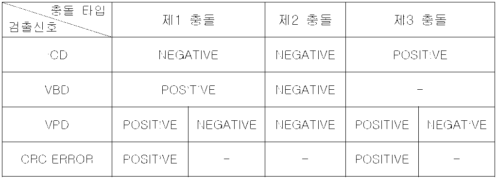
- the collision diagnosis unit 161 diagnoses the collision type for the received signal based on the valid preamble detection signal and the CRC error detection signal output from the reader receiver 140.
- the collision diagnosis unit 161 is configured to respond to the first collision, the second collision, and the third collision based on the reader collision detection signal output from the ICD module 162 and the valid bit detection signal output from the VBD module 163.
- the collision type can be diagnosed. An embodiment thereof will be referred to [Table 1].
- the collision diagnosis unit 161 may include a valid preamble detection signal and a CRC input from the reader receiver 140 to the reader collision detection signal output from the ICD module 162 and the valid bit detection signal output from the VBD module 163.
- the error detection signal it is possible to diagnose a more detailed collision type. An embodiment thereof will be referred to [Table 2] below.
- the collision diagnosis unit 161 determines that the collision situation is performed, and diagnoses as one of the first collision, the second collision, and the third collision, and does not satisfy the above conditions. If not, it is determined that a collision has not occurred in the received signal.
- the collision diagnosis unit 161 transmits the collision diagnosis result to the collision resolution unit 165.
- the collision diagnosis result includes whether a collision occurs, and when a collision occurs, includes collision type information.
- the collision solver 165 performs an operation corresponding to the collision diagnosis result applied from the collision diagnosis unit 161. In other words, if it is diagnosed that the collision has not occurred by the collision diagnosis unit 161, the collision resolution unit 165 notifies the reader control unit 110.
- the collision resolution unit 165 performs a collision resolution algorithm corresponding to each collision type. Try to resolve the conflict.
- the conflict resolution unit 165 includes a situation-specific command retransmission unit 1651 for determining whether to retransmit a command based on whether a collision occurs and a collision type, and a random wait time calculation unit for calculating a random wait time for retransmission of the command ( 1652, the specific operation of the conflict resolution unit 165 will be described after the operation of the collision diagnosis unit 161 diagnoses a collision.
- FIG. 5 is a view referred to for describing the operation of the collision control unit according to the present invention.
- the collision diagnosis unit 161 receives the reception signal data I1 from the reader receiver 140. At this time, the VBD module 163 of the collision diagnosis unit 161 detects a valid bit from the received signal data and outputs a valid bit detection signal I11. In addition, the ICD module 162 of the collision diagnosis unit 161 detects a reader collision from the received signal data and outputs a reader collision detection signal I12.
- the collision diagnosis unit 161 receives the valid preamble detection signal I2 and the CRC error detection signal I3 from the reader receiver 140.
- the collision diagnosis unit 161 receives the time information I4 from the timer 150. At this time, the collision diagnosis unit 161 counts the time until the reception time set for the transmission signal is timed out based on the time information I4 provided from the timer 150. In addition, the collision diagnosis unit 161 counts the time until the tag response corresponding to the transmission signal is received.
- the collision diagnosis unit 161 uses the valid bit detection signal I11, the reader collision detection signal I12, the valid preamble detection signal I2, and the CRC error detection signal I3 to determine whether a collision with the received signal occurs. And diagnose the type of collision that has occurred.
- the collision diagnosis unit 161 outputs a collision diagnosis result to the collision resolution unit 165, where the collision diagnosis result is No collision detected, the first collision, the second collision, and the third collision. Include information about Of course, the collision diagnosis result may include a conflict control command for solving the diagnosed conflict.
- 6 and 7 are views referred to for describing the operation of detecting the ICD in the ICD module of the collision diagnosis unit.
- the collision diagnosis unit 161 Prior to the ICD module 162 detecting the ICD signal, the collision diagnosis unit 161 adjusts the parameter value of the ICD module 162.
- the collision diagnosis unit 161 may determine a window (or tap) size of a moving average filter (MAF) from a link frequency (LF), a data rate, a signal modulation type, or the like.
- a window or tap
- the size of the window which is a section for calculating the average value of the received signal data, can be adjusted manually or automatically.
- the collision diagnosis unit 161 determines a tag response period for receiving a tag response to the transmission signal.
- the tag response period is determined from the link frequency, data rate, modulation type, and the like.
- the collision diagnosis unit 161 determines a reference level (Threshold_level) which is a reference for detecting the reader signal in the ICD module 162.
- the reference level is determined by at least one of a signal modulation type, a link frequency (LF), and a data rate.
- the ICD module 162 determines whether or not the RFID reader collides with the symbol data of the received signal input from the reader receiver 140. Check it.
- FIG. 6 is an exemplary view showing a configuration of an ICD module according to the present invention
- Figure 7 shows a signal flow in the ICD module.
- the ICD module 162 includes an average calculator 162a and a comparator 162b.
- the average calculator 162a receives the received signal data input from the reader receiver 140 as an input value and calculates an average value of the received received signal data.
- the average calculator 162a includes a moving average filter (MAF). That is, when the received signal data is input to the moving average filter (MAF), the average calculation unit 162a sums the respective filter values S1, S2, S3, ..., Sn into the window of the moving average filter and averages the average values. To calculate. That is, the average value of the section input to the window of the moving average filter is calculated. If the data of the received signal is additionally input to the window of the moving average filter, the average value of the additionally inputted received signal data is calculated.
- MAF moving average filter
- the comparator 162b compares the average value calculated from the average calculator 162a with the registered threshold level to output the reader collision detection signal. At this time, the comparator 162b outputs the reader collision detection signal to a value equal to or greater than a reference level among the average values calculated by the average calculator 162a. In this case, the collision diagnosis unit 160 considers that the reader collision detection signal, that is, the ICD is in a positive state.
- the collision diagnosis unit 161 considers the third collision to occur between the corresponding RFID reader and the neighboring RFID reader. At this time, the ICD value indicates a leader in a collision relationship.
- the collision diagnosis unit 160 receives the reception signal from the RF communication unit 130 during the set reception time after transmitting the transmission signal. In the present embodiment, the collision diagnosis unit 160 receives the reception signal during the tag response time T1. .
- the ICD module 162 compares the reference value (Threshold_level) previously determined by the collision diagnosis unit 161 among the average values of (b). As a result, the ICD module 162 outputs the reader collision detection signal to the collision diagnosis unit 161 as shown in FIG. That is, it can be confirmed that the ICD is in the 'positive' state in the area 'T2' which exceeds the reference level among the average values during the tag response time 'T1'.
- the collision diagnosis unit 161 determines that the third collision has occurred in the received signal based on the reader collision detection signal output from the ICD module 162.
- FIG. 8 illustrates an embodiment of detecting a valid bit in a VBD module.
- an example of detecting a valid bit in a received signal encoded by Miller-4 is shown.
- the VBD module 163 when the valid bit is detected by the VBD module 163, the VBD becomes 'positive', and when the valid bit is not detected, the VBD becomes 'negative'.
- the VBD module 163 outputs a valid bit detection signal according to the valid bit detection result. Accordingly, the collision diagnosis unit 161 diagnoses the collision type of the received signal based on the valid bit detection signal output from the VBD module 163.
- the collision diagnosis unit 161 may diagnose the collision type of FIGS. 9 to 11 from the previously obtained information, that is, the reader collision detection signal, the valid bit detection signal, the valid preamble detection signal, and the CRC error detection signal. do.
- FIG. 9 illustrates a first collision situation.
- FIG. 9 illustrates command and response signals transmitted and received between the RFID reader R and the tag 1 (T1) and the tag 2 (T2). However, it is assumed that there is no interference from other RFID readers.
- the tag 1 (T1) and the tag 2 (T2) send the response 1 and the response 2 to the RFID reader (R), respectively. send.
- a collision occurs as two or more tag responses, that is, a part of the response 1 and the response 2 overlap in the same response slot.
- the collision diagnosis unit 161 diagnoses that the first collision has occurred.
- the collision diagnosis unit 161 diagnoses that the first collision has occurred in the received signal.
- the collision diagnosis unit 161 diagnoses that the first collision has occurred in the received signal.
- the collision diagnosis unit 161 outputs a collision diagnosis result including the first collision information to the collision resolution unit 165.
- FIG. 10 illustrates a second collision situation.
- FIG. 10 illustrates a command and response signal transmitted and received between reader 1 and reader 2 and one tag.
- the RFID reader 1 (R1) and the RFID reader 2 (R2) output a command to the tag (T).
- a collision occurs when the command 1 and the command 2 output from the RFID reader 1 (R1) and the RFID reader 2 (R2) overlap, respectively.
- the tag cannot detect a command of a valid RFID reader, so that the tag response is not output. Therefore, the RF communication unit 130 receives a signal or noise of another RFID reader after transmitting the transmission signal.
- the collision diagnosis unit 161 diagnoses that the second collision has occurred.
- the collision diagnosis unit 161 diagnoses that a second collision has occurred in the received signal. .
- the collision diagnosis unit 161 outputs the collision diagnosis result including the second collision information to the collision solving unit 165.
- FIG. 11 illustrates a third collision situation.
- FIG. 11 illustrates command and response signals transmitted and received between reader 1 and reader 2 and one tag.
- the tag T transmits a response 1 to the RFID reader 1 R1 in response to the command 1 of the RFID reader 1 R1.
- the RFID reader 2 (R2) transmits a command 2 to another tag.
- FIG. 11A illustrates a case where a part of the response 1 overlaps with the command 2
- FIG. 11B illustrates a case where the entire response 1 overlaps the command.
- FIGS. 11A and 11B are generated according to an actual timing of a protocol data unit to be transmitted.
- the collision diagnosis unit 161 diagnoses that the third collision has occurred.
- the collision diagnosis unit 161 diagnoses that a third collision has occurred in the received signal.
- the collision diagnosis unit 161 diagnoses that a third collision has occurred in the received signal.
- the collision diagnosis unit 161 outputs the collision diagnosis result including the third collision information to the collision resolution unit 165 when ⁇ Condition D> or ⁇ Condition E> is satisfied.
- the collision resolver 165 may solve a collision diagnosed by the collision diagnosis unit 161 and perform a collision resolution algorithm corresponding to the generated collision type in order to minimize a collision that occurs. After the collision resolution unit 165 performs the collision resolution algorithm, the collision resolution unit 165 transmits the execution result to the reader controller 110.
- 12 to 14 are flowcharts illustrating an operation flow of an RFID reader according to an embodiment of the present invention.
- FIG. 12 shows the overall operation flow of the RFID reader.
- the RFID reader transmits a transmission signal, that is, an inventory command, to a nearby tag (S500).
- the RF communication unit 130 of the RFID reader receives a signal from the outside during the set reception time corresponding to the transmission signal transmitted in the 'S500' (S510).
- the RF communication unit 130 receives a tag response signal from at least one tag within a read range of the corresponding RFID reader.
- the signal received in the 'S510' process may include a signal or noise of another RFID reader in addition to the tag response signal.
- the collision diagnosis unit 161 of the RFID reader analyzes the data of the received signal received in the process 'S510' (S520), and diagnoses the collision occurrence and the collision type of the received signal (S530).
- step S530 If it is determined in step S530 that the received signal is a normal tag response signal (S550), the collision diagnosis unit 161 outputs a signal indicating this to the collision resolution unit 165. In this case, the collision resolution unit 165 transmits the collision diagnosis result of the collision diagnosis unit 161 to the reader control unit 110 so that the reader control unit 110 performs a corresponding operation according to the tag response (S570).
- the collision diagnosis unit 161 outputs the collision diagnosis result to the collision resolution unit 165.
- the collision resolution unit 165 performs a collision resolution algorithm corresponding to the collision type based on the collision diagnosis result of the collision diagnosis unit 161 (S560).
- FIG. 13 and 14 illustrate a detailed process of the process 'S530' in FIG. 12, FIG. 13 illustrates a brief operation flow, and FIG. 14 illustrates a more detailed operation flow of FIG. 13.
- the collision diagnosis unit 161 analyzes the data of the received signal input from the reader receiver 140, from the reader collision detection signal and the VBD module 163 output from the ICD module 162.
- the collision type generated in the received signal is diagnosed based on the output valid bit detection signal.
- the collision diagnosis unit 161 sets the collision type of the received signal as 'third collision type', that is, In this case, the diagnosis is made with the reader-to-reader collision type.
- the collision diagnosis unit 161 enters the 'S534' process and checks whether a CRC error has occurred. If it is determined that a CRC error has occurred, the collision diagnosis unit 161 diagnoses the collision type of the received signal as a 'third collision type', that is, a reader-to-reader collision type (S535). At this time, if it is determined that the CRC error does not occur in the 'S534' process, the collision diagnosis unit 161 diagnoses that the received signal is a normal tag response (S536).
- the collision diagnosis unit 161 of FIG. 4 determines whether a collision has occurred, and when the collision occurs, after determining whether the collision corresponds to one of three collision types according to the present invention, the determination is made.
- a method for resolving a conflict by the conflict resolution unit 165 having received the result will be described.
- the RFID reader can initiate an inventory round when ready, regardless of whether it currently occupies the selected frequency band. That is, LBT is not necessary unless a separate channel is assigned to the mobile RFID. In addition, there is no need to synchronize between readers transmitting within the same channel. That is, the present invention can be applied without securing a special control channel. It is an important aspect of the present invention to perform command retransmission according to a conflict situation in combination with adaptive retransmission latency.
- FIG. 15 is a flowchart illustrating a procedure in which the conflict resolution unit 165 retransmits a command for each collision situation according to an embodiment of the present invention.
- the procedure illustrated in FIG. 15 is mainly performed by the contextual command retransmission unit 1651 of FIG. 4.
- the random waiting time calculation unit 1652 of FIG. 4 calculates a random waiting time applied when the command is retransmitted for each collision situation and transmits the random waiting time to the situation-specific command retransmission unit 1651.
- the basic contents of command retransmission according to the conflict situation are as follows. First, if a multi-reader-to-tag conflict or reader-to-reader collision is detected, the command is resent. The leader must then suspend for a random time before retransmitting the command after a collision is detected. Since the collision is not detected while transmitting the command from the RFID reader, collision arbitration can be started after the transmission of the command is completed. That is, it is assumed that the transmission of the command in progress is not interrupted in the middle.
- Receiver timeout means that the receiver active time triggered by the tag state machine ends, for example without a valid RF modulation, encoding, or message structure or no activity on the communication channel. If there is a receiver timeout, the reader resends the command.
- Collision arbitration is implemented by retransmitting the command at least once. And, if a corrupted tag response is repeatedly received, the command can be retransmitted a plurality of times. Collision avoidance can be implemented by delaying the leader for a random wait time after a collision is detected to reduce the likelihood of subsequent collisions.
- the command will not be resent. That is, a reader that does not have a collision diagnosis function that can distinguish three types of communication collisions, such as the collision diagnosis unit 161 of the present invention, may be prohibited from resending the command. Instead, general tag collision adjustment is applied to resolve the case of tag to tag collision caused by multiple tags responding in the same communication slot.
- the number of retransmission attempts after the collision there may be no particular limitation on the number of retransmission attempts after the collision, and it may be appropriately adjusted according to the application. In order to avoid repeated communication traffic problems and the resulting communication collisions, it is desirable to set an upper limit on the number of failed retransmission attempts when a collision occurs.
- the reader detects the receiver timeout (not receiving the tag response within a given time), it retransmits the command only once. In the case of a receiver timeout, it is important for the present invention not to retransmit the command repeatedly. Instead, normal anti-collision applies if the receiver timeout continues. For example, if there are tags that are not yet detected in the reader area that are expected to be in the leader area prior to reissue (reissue) the command to recover from a multi-reader-to-tag collision, reduce the number of slots in the reader. Confirm that at least one tag that is allowed to respond is in the current slot.
- the command retransmission according to the invention is meaningful only if the relevant tag is able to receive the command.
- Retransmission of a command makes sense if the tag does not change its internal state due to a condition that is easy to receive the command, for example, a receiver timeout.
- the tag transitions to the Arbitrate state if there is a T 2 timeout in either the Reply state or Acknowledged state. At this time, even if the command is retransmitted after the waiting time of T 2 or more, the effect is not expected because there is no tag response.
- step S1100 the reader transmits a command.
- the reader receives a response in step S1102.
- step S1102 also includes a case in which there is no response to receive or a case in which no response is received.
- step S1104 determines whether a valid tag response is pending. For example, in the case of a Query, QueryAdjust, or QueryRep command, a valid tag response means that the tag should have responded in the current slot. In this case, the valid tag response is determined to be pending. If it is determined in step S1104 that it is determined that no valid tag response is pending, for example, if it is not necessary to receive a tag response, the flow proceeds to step S1106.
- Step S1104 may be applied in other ways, or may be omitted depending on the design.
- step S1106 it is determined whether there are more instructions to be processed by the reader. If there are more commands to process, the process proceeds to step S1108 to transmit the next reader command and receives a response in step S1102. If there are no more commands to process, the process proceeds to step S1110 to stop the reader.
- Step S1112 is a collision detection step of determining whether a collision has occurred and the type of the collision by the collision diagnosis unit according to the present invention. If there is a conflict as a result of the determination of the collision diagnosis unit, the process proceeds to step S1122 while transmitting the collision and the determined type of the collision to the collision resolution unit, and if the collision diagnosis unit determines that there is no collision, the collision did not occur. Proceed to step S1114 while transmitting a signal to the collision solving unit.
- step S1114 it is determined whether or not the receiver has timed out. As a result of the determination, if it is not the receiver timeout, the process proceeds to step S1106 to process the next command, and if it is the receiver timeout, the process proceeds to step S1116.
- step S1116 it is determined whether the tag is already separated. When the tag is separated, it means that the tag is separated into the current response slot, for example, the tag ACK and the tag access period. If it is determined in step S1116 that the tag is not yet separated, the process proceeds to step S1124 without executing the command retransmission according to the present invention and performs a general tag collision adjustment procedure. That is, according to the present invention, the leader who is still in the early stage of the inventory round does not perform retransmission of the command, thereby increasing the possibility that another leader can complete the inventory round first.
- step S1116 determines whether the tag has already been separated. If it is determined in step S1116 that the tag has already been separated, the flow proceeds to step S1118. In step S1118, it is determined whether the command has already been retransmitted. If it is determined in step S1118 that the instruction has already been resent, the process proceeds to step S1124 to perform a tag collision adjustment procedure. On the other hand, if it is determined in step S1118 that the command has not been retransmitted, the flow advances to step S1120 to retransmit the command. That is, if the reader detects the receiver timeout and the tag is already detached, it will resend the command only once. Thus, in case of a receiver timeout, the command is not repeatedly retransmitted, and when there is a receiver timeout even after one command retransmission, general tag collision adjustment is performed.
- step S1122 when the flow returns to step S1112 and determines that there is a collision as a result of the determination in step S1112, the collision resolver receives the type of collision (one of three collision types according to the present invention) and proceeds to step S1122.
- step S1122 according to the type of collision, it is determined whether to proceed to step S1124 to perform tag collision adjustment, or to proceed after step S1126 to perform command retransmission. If the type of collision is 'tag-to-tag collision', the flow proceeds to step S1124 to perform tag collision adjustment. If the collision type is 'multi-reader-tag collision' or 'reader-to-reader collision', the procedure after step S1126 is performed.
- step S1126 it is determined in step S1126 whether the number of retransmissions has reached the maximum number of retransmissions.
- the maximum number of retransmissions is a design value and may vary depending on the application. By limiting the maximum number of retransmissions, a situation in which retransmissions are continuously repeated can be prevented, but this restriction is not essential.
- the process proceeds to step S1124 without resending the command to perform tag collision adjustment.
- step S1126 If it is determined in S1126 that the maximum number of retransmissions has not been reached, the procedure goes to step S1128. If it is determined in step S1128 that the tag has already been detached, the flow proceeds to step S1120 to resend the command without delaying the reader, and if it is determined that the tag has not yet been detached, for example, in the initial stage of the inventory round, In step S1130, a random waiting time is obtained and the reader is delayed by the obtained random waiting time.
- the random waiting time is calculated by the random waiting time calculator 1652 of FIG. 4 to obtain a calculated random waiting time, and the reader is delayed by the obtained random waiting time.
- a method of calculating the random wait time performed by the random wait time calculator 1652 will be described in detail later.
- the reader delayed by the random waiting time by performing step S1130 proceeds to step S1120 to retransmit the command and returns to step S1102 to receive a response.
- the procedure described with reference to FIG. 15 is exemplary and some modifications and omissions may be made without departing from the spirit of the invention.
- FIG. 16 is a pseudo-code notation of the collision resolution algorithm described with reference to FIG. 15 and is written in a manner similar to that used in the C language.
- This pseudo code expression is written mainly using the concept and terminology of mobile RFID reader defined by air interface specification as defined in ISO / IEC 18000-6 Type C.
- the code presented is for illustrative purposes and is not intended to limit the scope of the invention.
- FIG. 16 is for reference only. Since the procedure illustrated in FIG. 15 is represented by a code, detailed description thereof will be omitted. Those skilled in the art will readily understand with reference to the description of the present invention.
- This code assumes the reader is always active, and the anticollision () function represents the collision mediation mechanism of the conventional air interface specification.
- additional inventory commands such as QueryAdjust or QueryRep in case of receiver timeout, by checking some preconditions, for example, the number of slots must be greater than one.
- 17 to 19 are exemplary timing diagrams for describing a conflict resolution method according to each collision situation according to an embodiment of the present invention.
- An example of applying a random delay time when a collision occurs between two readers R 1 and R 2 and one tag T is given.
- a random waiting time is introduced, which is denoted by T R.
- T R a random waiting time
- Random wait times may be applied between commands, for example between Query and QueryAdjust in the case of ISO / IEC 18000-6 Type C.
- FIG. 17 illustrates a sequence of applying a random wait time when a multi-reader to tag collision occurs.
- Reader (R 1 ) issued a Select command and a Query command and received an Rn16 response from the tag.
- the reader R 1 has already singulated one tag, and the reader R 2 has not singulated any tags.
- the reader R 1 transmits an ACK command but a collision occurs with the select command of the reader R 2 transmitted at the same time.
- the reader (R 1 ) has already removed the tag (T). Therefore, the reader R 1 immediately retransmits the final command ACK according to the timing protocol of ISO / IEC 18000-6 Type C, and the reader R 2 is delayed during the random waiting time T R.
- T 3 means the time the reader waits after T 1 before issuing another command.
- the reader R 2 performs steps S1112, S1122, S1126, S1128, S1130, and S1120 in order to delay the reader for a random waiting time and then resend the command.
- the reader R 1 can successfully receive the tag response consisting of PC + UII + CRC16, and the multi-reader-to-tag conflict is resolved.
- FIG. 18 illustrates a leader-to-leader collision in which two leaders collide at an early stage of an inventory round.
- both the reader R 1 and the reader R 2 are delayed for a random waiting time T R , and the reader R 1 then sends a QueryAdjust command and an ACK command and responds to Rn16 and PC + UII + CRC16. Can be successfully received and the leader-to-leader conflict is resolved.
- FIG. 19 also shows a sequence that is performed when the reader R 1 has already advanced to detach a tag when a leader-to-reader collision occurs.
- the reader (R 1 ) has already singulated one tag, and the reader (R 2 ) has not been able to singulate any tags.
- leader R 1 retransmits the ACK after T 2 , and leader R2 is delayed during T R , thereby solving the leader to leader conflict.
- an RFID reader has three stages: select, inventory, and access. If no tags have yet been acknowledged in the current inventory pass (tags are singulated and sent an ACK but no response is received), the tag select phase or the tag inventory phase The reader is delayed for a random wait time before resending the command.
- singulation refers to a procedure of separating a tag by forcing the tag to an unoccupied response slot to read the UII of the tag.
- the reader is not delayed during tag access.
- Random latency is not applied by default, but only if the leader is in the early stages of an inventory round. It only applies if the tag has not yet been detached. Otherwise, both colliding readers will automatically be delayed after the collision and continue to issue commands almost in parallel after a short transmission break, which will again generate a collision (subsequent collision). Instead, if only one of the two leaders is blocked and delayed for a sufficient amount of time, then the other leader can resend the final command, during which all inventory rounds can be ended.
- the random latency T R should be chosen to maximize performance and minimize the possibility of subsequent collisions. Therefore, in order to achieve a good result on average, the waiting time is randomly selected in the range defined by the minimum retransmission waiting time (MinWaitTime) and the maximum retransmission waiting time (MaxWaitTime) and this is determined as the random waiting time.
- MinWaitTime minimum retransmission waiting time
- MaxWaitTime maximum retransmission waiting time
- the random wait time may select a random integer between the reference value defined by Fmin (MinWaitTime) and Fmax (MaxWaitTime), and select an integer value corresponding to the number of clock cycles corresponding to the time value between the values given by Fmin and Fmax. You can also choose.
- the protocol data unit means a data block of a certain size when data is transmitted, and is a kind of data package transmitted by an RFID reader or an RFID tag, and includes a reader command and a tag response. During the race period the leader command or tag response is vulnerable and can be destroyed by interference. In order to reduce the vulnerability of a single protocol data unit or a typical command sequence issued during tag inventory, it is desirable to select a random latency in proportion to the duration of the protocol data unit.
- MinWaitTime (Fmin)
- MinWaitTime c * duration (longestExpectedPDU)
- c is a constant value (dynamically changeable) that can be set according to the actual application and environment, and 'duration' returns the time required to transmit a protocol data unit on the air interface at the selected link rate.
- c is referred to as a 'wait time parameter'.
- the longestExpectedPDU is a 'expected longest protocol data unit', for example, a PC + UII + CRC16 tag response shown in FIG. 20.
- the lower limit of random latency is determined (minimum retransmission latency), so if two competing readers R 1 and R 2 use the same link speed and the lower bound of the calculated random latency is the same If the R 2 retransmits the inventory command due to a communication collision after a random delay, it can be ensured that subsequent collisions will not occur by the same protocol data unit.
- FIG. 20 is a timing diagram illustrating the meaning of a minimum retransmission wait time according to an embodiment of the present invention.
- the reader (R 1 ) has already singulated the tag (T) to the current response slot, but the reader (R 1 ) fails to acknowledge the tag due to the reader (R 2 ) that issued a Query command that conflicts with the tag response. did.
- tags do not stop transmission in the event of a collision, so to avoid subsequent collisions, at least the tag (T) consists of a PC (Protocol control), a Unique Item Identifier (UII), and a Cyclic Redundancy Check 16 (CRC16).
- FIG. 20 illustrates a case in which the reader R 2 is delayed by a minimum retransmission waiting time and retransmits a command. Subsequent conflicts with other commands issued by reader R 1 may still occur, but setting the maximum retransmission wait time to a value that is much larger than the minimum retransmission wait time may minimize this problem.
- the expected longest protocol data unit may vary from reader to reader.
- the return link rate read by the reader during the inventory round can be used for the determination of the expected longest protocol data unit. For example, even if the number of bits to be received is not known in advance, such as the backscatter of UII, the maximum number of bits possible for the current application can be expected. This means, for example, that even if the maximum length of the tag backscatter supported by the air interface specification is larger, if the current application supports UII lengths up to 96 bits, then values greater than 96 bits may not be used to determine the expected longest PDU. It means that there is.
- MaxWaitTime (Fmax) which is the upper limit of the random waiting time
- MaxWaitTime c * duration (Select + T 4 + Query + T 1 + RN16 + T 2 + ACK + T 1 + UII)
- T 1 is the time from the reader transmission to the tag response
- T 2 is the time from the tag response to the reader transmission
- the reader sends the Select command and the Query command after the time of T 4
- the tag responds with RN16 after the time of T 1
- the reader sends the ACK command after the time of T 2
- the UII includes PC, UII, and CRC16 as described above.
- the result returned by the duration function used in the maximum retransmission latency expression depends on the forward and return link rates that the reader will use in the next inventory round and the expected length of the tag response for the ACK command. As described for the minimum retransmission latency, one can estimate and use the maximum number of bits possible in the current application to determine the length of the UII to be backscattered by the tag.
- 'Select + T 4 + Query + T 1 + RN16 + T 2 + ACK + T 1 + UII' used in the calculation of maximum retransmission wait time is an example and corresponds to 'Total estimated time required for reader command and tag response'. Is a value. Depending on the air interface specification and the application used, this value may vary. If tag access is performed, the associated additional reader command and tag response are used to calculate the maximum retransmission latency.
- FIG. 21 is a timing diagram illustrating the meaning of a maximum retransmission wait time according to an embodiment of the present invention.
- the lengths of the expected select and inventory steps are determined by 'Select + T 4 + Query + T 1 + RN16 + T 2 + ACK + T 1 + UII'. It is shown that the reference value determined according to the maximum retransmission latency equation can potentially resolve the collision between reader R 1 and reader R 2 .
- the minimum retransmission latency and the maximum retransmission latency are determined by the link speed used and the protocol data unit to be transmitted.
- adaptive retransmission waiting time calculation according to an embodiment of the present invention will be described.
- the latency parameter c value used in the minimum retransmission latency and maximum retransmission latency equations described above, it best meets the requirements of the actual application and between performance and subsequent conflicts according to the actual application scenario.
- the latency parameter c is used to tune the random latency by multiplying the lower and upper bounds of the retransmission latency reference value.
- the 'retransmission waiting threshold' is a value multiplied by c in the minimum retransmission waiting time and the maximum retransmission waiting time equation described above, and the time required for the expected longest protocol data unit in the minimum retransmission waiting time is the lower limit of the retransmission waiting reference value, and the maximum In retransmission wait time, the total estimated time required for reader command and tag response is the upper limit of the retransmission wait reference value.
- the wait time parameter c can be changed for the remaining inventory round periods without further restriction. That is, the waiting time parameter c may be increased or decreased at any time according to the judgment of the user. If the wait time parameter c is fixed, static retransmission wait time can be calculated.
- the air interface specification allows the user to define the link speed, allowing two competing readers to operate at different link speeds. In this case, there may be a difference between the minimum and maximum retransmission wait times calculated by the reader R 1 and the reader R 2 . Thus, it is necessary to adjust the parameter c in case of subsequent collisions that are recurrent. Conversely, if the number of collisions observed is kept small, the same parameters may be used to improve overall performance.
- the method of changing the latency parameter c during the inventory round is described in detail below.
- FIG. 23 is a flowchart illustrating a procedure of dynamically changing a wait time parameter c according to a current collision rate.
- the wait time parameter c is a parameter used for calculating the minimum retransmission waiting time and the maximum retransmission waiting time, and is a value multiplied by the retransmission waiting threshold.
- the current collision percentage is, for example, the average number of collisions per command of the reader.
- Step S1900 means the start of a new inventory round.
- the wait time parameter c is set to an initial value in step S1902.
- the initial value of c is set to 1.0. This initial value does not change until at least one tag is acknowledged.
- step S1904 determines whether the tag has been acknowledged. If the tag has not yet been acknowledged as a result of the determination in step S1904, the process returns to step S1902 to maintain or reset the wait time parameter c to an initial value or to an initial value. If the tag in the determination result in step S1904 has been acknowledged, the flow proceeds to step S1906. In step S1906, it is determined whether the current collision percentage is less than the collision percentage threshold. If the determination result at step S1906 is that the current collision rate is less than the collision rate reference value, the flow advances to step S1908 to decrease the wait time parameter c by the parameter change factor f. That is, after the first tag detection (acknowledgment), if the collision rate is lower than a predefined reference value, c is reduced by a factor f to improve performance.
- step S1906 If it is determined in step S1906 that the current collision rate is not less than the collision rate reference value, the process proceeds to step S1910 to determine whether the current collision rate exceeds the collision rate reference value. If the collision rate is higher than the predefined reference value, the flow advances to step S1912 to increase c by a factor f, thereby reducing the subsequent collision probability by extending the average retransmission wait time.
- the value of the parameter change factor f may vary depending on the actual situation and should be selected to suit the needs of the application. In general, the parameter change factor f can be set to a value between 0.1 and 1.0, and can be set to a value that is dynamically changed instead of a fixed value.
- step S1910 If it is determined in step S1910 that the collision rate does not exceed the collision rate reference value (if the collision rate is equal to the reference value), the process returns to step S1904 without changing c.
- the collision rate reference value referred to in this embodiment depends on the actual application scenario. For example, you can set a high threshold if you expect a large number of mobile RFID users located nearby, such as a bus stop, or if you expect a small number of users, for example if you use RFID at home. It can be set small.
- collision percentage refers to the percentage of tag responses missed due to interference, that is, the reader has not successfully decoded.
- FIG. 24 is a flowchart illustrating a procedure of dynamically changing a wait time parameter c according to a current collision rate and a timeout rate as an extension of the procedure of FIG. 23.
- the receiver timeout ratio ratio of unanswered reader commands
- the wait time parameter c is dynamically increased or reset.
- step S2006 means that the reader can detect a collision by evaluating the received bit stream. This is a multi-reader that can only be identified on the tag side.
- the receiver timeout on the reader side does not always occur due to no matching tag in the current response slot, but may indicate a hidden multi-reader-to-tag collision.
- the present embodiment has the timeout ratio exceeded the reference value in step S2018? Conditions and step S2012 'Did the collision rate exceed the reference value?' The conditions are organically bound.
- Timeout percentage' represents the percentage of reader commands that have not been answered. For example, if the reader sent four commands, and only two of them received a (valid or invalid) response, the timeout rate is 0.5. Commands that do not require a tag response, such as Select, are not used to calculate the timeout rate.
- the timeout rate threshold will depend on the actual application and will vary from scenario to scenario.
- This embodiment ensures that if a collision has already reached its peak when the receiver timeout is observed, then retransmission due to the receiver timeout no longer exacerbates the current collision situation. Also, if the current timeout rate falls below the timeout rate reference value, the wait time parameter c is reset back to its initial value for protocol performance.
- the term 'collision' in this embodiment means all forms of collision and does not cause any difference between the three collisions according to the invention.
- step S2000 means the start of a new inventory round.
- the wait time parameter c is set to an initial value in step S2002.
- the initial value of c is set to 1.0. This initial value does not change until at least one tag is acknowledged.
- step S2004 determines whether the tag has been acknowledged. If the tag is not yet acknowledged as a result of the determination in step S2004, the process returns to step S2002 to maintain the wait time parameter c as the initial value. If the tag in the determination result in step S2004 has been acknowledged, the flow proceeds to step S2006.
- step S2006 it is determined whether the collision is visible. That is, the received bit stream is evaluated to determine whether a collision can be detected by the reader. If it is determined that the collision is observable, the flow proceeds to step S2008 to determine whether the current collision ratio is less than the collision ratio reference value. As a result of the determination in step S2008, if the current collision rate is less than the collision rate reference value, the flow advances to step S2010 to reduce the wait time parameter c by the parameter change factor f.
- step S2008 determines whether the current collision rate is not less than the collision rate reference value. If it is determined in step S2008 that the current collision rate is not less than the collision rate reference value, the process proceeds to step S2012 to determine whether the current collision rate exceeds the collision rate reference value. If the collision rate is higher than the predefined reference value, the process proceeds to step S2014 to increase c by a factor f, thereby reducing the subsequent collision probability by extending the average retransmission wait time. If the determination result in step S2012 is that the collision rate does not exceed the collision rate reference value (if the collision rate is equal to the reference value), the process returns to step S2006 without changing c.
- step S2006 determines whether the collision is not observable. If it is determined in step S2006 that the collision is not observable, the flow proceeds to step S2016 to determine whether the timeout is observable. If no timeout is observable, proceed to step S2002 to reset c to an initial value, but if timeout is observable, proceed to step S2018 to determine whether the timeout ratio exceeds a predefined timeout ratio reference value. Judge. In step S2018, if it is determined that the timeout ratio is equal to or less than the reference value, the process returns to step S2002. If it is determined that the timeout ratio exceeds the reference value, the flow advances to step S2012 to compare the collision rate with the reference value. By repeating this procedure every inventory round, it is possible to adaptively change the retransmission wait time.
- the air interface specification of the mobile RFID reader of the present invention described above may be applied in combination with a conventional air interface specification developed for use in a static RFID reader.
- the present invention is not limited to the configuration and method of the embodiments described as described above, the embodiments may be configured by selectively combining all or some of the embodiments so that various modifications can be made.
- the present invention reduces the possibility of collision by being used in the mobile RFID system, can identify the cause of the collision when a collision occurs, and can contribute significantly to the expansion of the base of the mobile RFID by adaptively solving the collision according to the causes and aspects. will be.
Landscapes
- Engineering & Computer Science (AREA)
- Physics & Mathematics (AREA)
- Toxicology (AREA)
- Health & Medical Sciences (AREA)
- Computer Vision & Pattern Recognition (AREA)
- Artificial Intelligence (AREA)
- Computer Networks & Wireless Communication (AREA)
- General Physics & Mathematics (AREA)
- Theoretical Computer Science (AREA)
- Electromagnetism (AREA)
- General Health & Medical Sciences (AREA)
- Signal Processing (AREA)
- Mobile Radio Communication Systems (AREA)
- Near-Field Transmission Systems (AREA)
- Communication Control (AREA)
Abstract
Description

Claims (20)
- 하나 이상의 태그와 신호를 송수신 할 수 있는 RF 통신부로부터의 송신신호에 대응하여 설정된 수신시간 동안에 수신된 수신신호의 데이터를 분석하여, 상기 수신신호의 충돌발생 여부를 확인하고, 수신 신호 데이터의 분석 결과에 따라 충돌 타입을 진단하는 충돌 진단부; 및상기 충돌 진단부로부터 수신한 충돌발생 여부 및 충돌 타입에 근거하여, 충돌 상황에 따라 RF 통신부를 통해 태그로 명령을 재전송할 수 있도록 하는 충돌 해결부를 구비하고,상기 충돌 해결부는, 충돌발생 여부와 충돌 타입에 근거하여 명령을 재전송할지 여부를 판단하는 상황별 명령 재전송부 및 명령의 재전송을 위한 랜덤 대기 시간을 계산하는 랜덤 대기 시간 계산부를 포함하는, 충돌 상황에 따라 명령을 재전송하는 RFID 리더 장치.
- 청구항 1에 있어서,상기 충돌 진단부가 진단하는 충돌 타입은, 태그 대 태그 충돌, 멀티 리더 대 태그 충돌, 및 리더 대 리더 충돌을 포함하는 것을 특징으로 하는 RFID 리더 장치.
- 청구항 1에 있어서,상기 충돌 해결부는, 수신한 충돌 타입이 멀티 리더 대 태그 충돌 또는 리더 대 리더 충돌인 경우, 명령을 재전송하는 것을 특징으로 하는 RFID 리더 장치.
- 청구항 3에 있어서,상기 충돌 해결부는, 태그가 분리되어 있지 않다고 판단하면 상기 랜덤 대기 시간 계산부가 계산한 랜덤 대기 시간 만큼 지연한 후 명령을 재전송하는 것을 특징으로 하는 RFID 리더 장치.
- 청구항 3에 있어서,상기 충돌 해결부는, 태그가 현재의 응답 슬롯으로 분리되어 있다고 판단하면 랜덤 대기 시간 만큼 지연하지 않고 명령을 재전송하는 것을 특징으로 하는 RFID 리더 장치.
- 청구항 3에 있어서,상기 충돌 해결부는, 최대 재전송 횟수에 도달했다고 판단한 경우 명령을 재전송하지 않고 태그 충돌 조정(anti-collision)을 수행하도록 하는 것을 특징으로 하는 RFID 리더 장치.
- 청구항 1에 있어서,상기 충돌 해결부는, 리시버 타임아웃이 발생한 경우, 명령을 재전송하는 것을 특징으로 하는 RFID 리더 장치.
- 청구항 7에 있어서,상기 충돌 해결부는, 리시버 타임아웃이 발생하고, 태그가 현재의 응답 슬롯으로 분리되어 있다고 판단되는 경우에 명령을 재전송하는 것을 특징으로 하는 RFID 리더 장치.
- 청구항 7에 있어서,상기 충돌 해결부는, 리시버 타임아웃이 발생한 경우, 명령을 한 번만 재전송하는 것을 특징으로 하는 RFID 리더 장치.
- 청구항 7에 있어서,명령 전송 후 정해진 시간 내에 태그 응답을 수신하지 못하는 경우에, 리시버 타임아웃이 발생했다고 판단하는 것을 특징으로 하는 RFID 리더 장치.
- 충돌 진단부 및 충돌 해결부를 구비하고 충돌 상황에 따라 명령을 재전송하는 RFID 리더 장치의 제어 방법으로서,상기 충돌 진단부가, RF 통신부로부터의 송신신호에 대응하여 설정된 수신시간 동안에 수신된 수신신호의 데이터를 분석하여, 상기 수신신호의 충돌발생 여부를 확인하고, 수신 신호 데이터의 분석 결과에 따라 충돌 타입을 진단하는 충돌 진단 단계; 및상기 충돌 해결부가, 충돌발생 여부와 충돌 타입에 근거하여 충돌 상황에 따라 RF 통신부를 통해 태그로 명령을 재전송할 수 있도록 하는 충돌 해결 단계를 포함하고,상기 충돌 해결 단계는, 충돌발생 여부와 충돌 타입에 근거하여 명령을 재전송할지 여부를 판단하는 상황별 명령 재전송 단계 및 명령의 재전송을 위한 랜덤 대기 시간을 계산하는 랜덤 대기 시간 계산 단계를 포함하는, RFID 리더 장치의 제어 방법.
- 청구항 11에 있어서,상기 충돌 진단 단계에서 진단하는 충돌 타입은, 태그 대 태그 충돌, 멀티 리더 대 태그 충돌, 및 리더 대 리더 충돌을 포함하는 것을 특징으로 하는 RFID 리더 장치의 제어 방법.
- 청구항 11에 있어서,상기 충돌 해결 단계에 있어서, 충돌 타입이 멀티 리더 대 태그 충돌 또는 리더 대 리더 충돌인 경우, 명령을 재전송하는 것을 특징으로 하는 RFID 리더 장치의 제어 방법.
- 청구항 13에 있어서,상기 충돌 해결 단계에 있어서, 태그가 분리되어 있지 않다고 판단하면 상기 랜덤 대기 시간 계산부가 계산한 랜덤 대기 시간 만큼 지연한 후 명령을 재전송하는 것을 특징으로 하는 RFID 리더 장치의 제어 방법.
- 청구항 13에 있어서,상기 충돌 해결 단계에 있어서, 태그가 현재의 응답 슬롯으로 분리되어 있다고 판단하면 랜덤 대기 시간 만큼 지연하지 않고 명령을 재전송하는 것을 특징으로 하는 RFID 리더 장치의 제어 방법.
- 청구항 13에 있어서,상기 충돌 해결 단계에 있어서, 최대 재전송 횟수에 도달했다고 판단한 경우 명령을 재전송하지 않고 태그 충돌 조정(anti-collision) 단계를 수행하도록 하는 것을 특징으로 하는 RFID 리더 장치의 제어 방법.
- 청구항 11에 있어서,상기 충돌 해결 단계에 있어서, 리시버 타임아웃이 발생한 경우, 명령을 재전송하는 것을 특징으로 하는 RFID 리더 장치의 제어 방법.
- 청구항 17에 있어서,상기 충돌 해결 단계에 있어서, 리시버 타임아웃이 발생하고, 태그가 현재의 응답 슬롯으로 분리되어 있다고 판단되는 경우에 명령을 재전송하는 것을 특징으로 하는 RFID 리더 장치의 제어 방법.
- 청구항 17에 있어서,상기 충돌 해결 단계에 있어서, 리시버 타임아웃이 발생한 경우, 명령을 한 번만 재전송하는 것을 특징으로 하는 RFID 리더 장치의 제어 방법.
- 청구항 17에 있어서,명령 전송 후 정해진 시간 내에 태그 응답을 수신하지 못하는 경우에, 리시버 타임아웃이 발생했다고 판단하는 것을 특징으로 하는 RFID 리더 장치의 제어 방법.
Priority Applications (2)
| Application Number | Priority Date | Filing Date | Title |
|---|---|---|---|
| US12/921,984 US8779899B2 (en) | 2008-03-12 | 2009-03-12 | RFID interrogator retransmitting command depending on collision situation and control method thereof |
| JP2010550602A JP5094979B2 (ja) | 2008-03-12 | 2009-03-12 | 衝突状況に応じて命令を再伝送するrfidリーダー装置及びその制御方法 |
Applications Claiming Priority (4)
| Application Number | Priority Date | Filing Date | Title |
|---|---|---|---|
| US3580108P | 2008-03-12 | 2008-03-12 | |
| US61/035,801 | 2008-03-12 | ||
| US14031208P | 2008-12-23 | 2008-12-23 | |
| US61/140,312 | 2008-12-23 |
Publications (2)
| Publication Number | Publication Date |
|---|---|
| WO2009113827A2 true WO2009113827A2 (ko) | 2009-09-17 |
| WO2009113827A3 WO2009113827A3 (ko) | 2010-05-20 |
Family
ID=41065677
Family Applications (1)
| Application Number | Title | Priority Date | Filing Date |
|---|---|---|---|
| PCT/KR2009/001255 WO2009113827A2 (ko) | 2008-03-12 | 2009-03-12 | 충돌 상황에 따라 명령을 재전송하는 rfid 리더 장치 및 그 제어방법 |
Country Status (4)
| Country | Link |
|---|---|
| US (1) | US8779899B2 (ko) |
| JP (1) | JP5094979B2 (ko) |
| KR (1) | KR101527368B1 (ko) |
| WO (1) | WO2009113827A2 (ko) |
Families Citing this family (16)
| Publication number | Priority date | Publication date | Assignee | Title |
|---|---|---|---|---|
| US9071282B1 (en) * | 2012-02-02 | 2015-06-30 | Google Inc. | Variable read rates for short-range communication |
| US8638190B1 (en) | 2012-02-02 | 2014-01-28 | Google Inc. | Gesture detection using an array of short-range communication devices |
| KR102012729B1 (ko) * | 2012-08-29 | 2019-08-21 | 한국전자통신연구원 | 알에프아이디를 이용한 거리 한계 측정 방법 및 거리 한계 측정 시스템 |
| US9477865B2 (en) * | 2013-12-13 | 2016-10-25 | Symbol Technologies, Llc | System for and method of accurately determining true bearings of radio frequency identification (RFID) tags associated with items in a controlled area |
| KR101521262B1 (ko) * | 2014-03-31 | 2015-06-01 | 대전대학교 산학협력단 | Rfid 태그, rfid 태그 리더, 이들을 포함하는 rfid 태그 인식 시스템 및 그 제공방법 |
| CN105095943A (zh) * | 2014-05-23 | 2015-11-25 | 中兴通讯股份有限公司 | 反射式无源光学标签、光读写装置及智能光分配网络 |
| CN105095928A (zh) * | 2014-05-23 | 2015-11-25 | 中兴通讯股份有限公司 | 无源射频识别标签、射频读写头及射频识别系统 |
| CN105095929A (zh) * | 2014-05-23 | 2015-11-25 | 中兴通讯股份有限公司 | 无源射频识别标签、光学射频读写头及射频识别系统 |
| US9755294B2 (en) | 2014-07-07 | 2017-09-05 | Symbol Technologies, Llc | Accurately estimating true bearings of radio frequency identification (RFID) tags associated with items located in a controlled area |
| KR101589526B1 (ko) * | 2015-02-13 | 2016-01-28 | 성균관대학교산학협력단 | 다중 패킷 수신이 가능한 rfid 시스템의 태그 충돌 방지 방법 및 태그 인식 장치, 및 시스템 |
| US9773136B2 (en) | 2015-10-19 | 2017-09-26 | Symbol Technologies, Llc | System for, and method of, accurately and rapidly determining, in real-time, true bearings of radio frequency identification (RFID) tags associated with items in a controlled area |
| US10726218B2 (en) | 2017-07-27 | 2020-07-28 | Symbol Technologies, Llc | Method and apparatus for radio frequency identification (RFID) tag bearing estimation |
| US10367667B2 (en) | 2017-09-29 | 2019-07-30 | Nxp B.V. | Joint ad-hoc signal and collision detection method |
| CN112543917A (zh) * | 2018-07-30 | 2021-03-23 | 三菱电机株式会社 | 中断控制装置、中断控制方法及中断控制程序 |
| JP6993306B2 (ja) * | 2018-07-30 | 2022-01-13 | 富士通フロンテック株式会社 | Rfidリーダライタ、読取制御方法および読取方法制御プログラム |
| CN118215150A (zh) * | 2018-08-24 | 2024-06-18 | 华为技术有限公司 | 实现数据传输的冲突检测方法及装置 |
Citations (3)
| Publication number | Priority date | Publication date | Assignee | Title |
|---|---|---|---|---|
| US6566997B1 (en) * | 1999-12-03 | 2003-05-20 | Hid Corporation | Interference control method for RFID systems |
| WO2007081119A1 (en) * | 2006-01-12 | 2007-07-19 | D & S Technology Co., Ltd. | Method of preventing collisions between rfid readers in rfid system |
| US20070236332A1 (en) * | 2006-03-22 | 2007-10-11 | Chenghao Quan | Method for reading tag in mobile rfid environment |
Family Cites Families (9)
| Publication number | Priority date | Publication date | Assignee | Title |
|---|---|---|---|---|
| JPH10124633A (ja) * | 1996-10-18 | 1998-05-15 | Omron Corp | 非接触媒体処理装置、入退室管理装置および非接触媒体処理方法 |
| US6813260B1 (en) * | 2000-03-16 | 2004-11-02 | Ericsson Inc. | Systems and methods for prioritized access in a contention based network |
| US7009496B2 (en) * | 2002-04-01 | 2006-03-07 | Symbol Technologies, Inc. | Method and system for optimizing an interrogation of a tag population |
| JP4214793B2 (ja) * | 2003-02-19 | 2009-01-28 | 日本電気株式会社 | 無線通信システム、サーバ、基地局、移動端末及びそれらに用いる再送タイムアウト時間決定方法 |
| JP2005117301A (ja) * | 2003-10-07 | 2005-04-28 | Hitachi Kokusai Electric Inc | 通信装置 |
| AU2005275050A1 (en) * | 2004-07-15 | 2006-02-23 | Mastercard International Incorporated | Reference equipment for testing contactless payment devices |
| JP4394007B2 (ja) | 2005-01-13 | 2010-01-06 | 三菱電機株式会社 | リーダライタ装置 |
| KR100623066B1 (ko) * | 2005-09-29 | 2006-09-13 | 인하대학교 산학협력단 | 미리 분배된 난수를 이용한 rfid 태그 정보 충돌 방지장치 및 그 방법 |
| JP2007241392A (ja) * | 2006-03-06 | 2007-09-20 | Fujitsu Ltd | タグ通信装置およびタグ通信方法 |
-
2009
- 2009-03-12 US US12/921,984 patent/US8779899B2/en active Active
- 2009-03-12 KR KR1020090021373A patent/KR101527368B1/ko active IP Right Grant
- 2009-03-12 JP JP2010550602A patent/JP5094979B2/ja not_active Expired - Fee Related
- 2009-03-12 WO PCT/KR2009/001255 patent/WO2009113827A2/ko active Application Filing
Patent Citations (3)
| Publication number | Priority date | Publication date | Assignee | Title |
|---|---|---|---|---|
| US6566997B1 (en) * | 1999-12-03 | 2003-05-20 | Hid Corporation | Interference control method for RFID systems |
| WO2007081119A1 (en) * | 2006-01-12 | 2007-07-19 | D & S Technology Co., Ltd. | Method of preventing collisions between rfid readers in rfid system |
| US20070236332A1 (en) * | 2006-03-22 | 2007-10-11 | Chenghao Quan | Method for reading tag in mobile rfid environment |
Also Published As
| Publication number | Publication date |
|---|---|
| US20110006885A1 (en) | 2011-01-13 |
| KR101527368B1 (ko) | 2015-06-09 |
| WO2009113827A3 (ko) | 2010-05-20 |
| KR20090097830A (ko) | 2009-09-16 |
| US8779899B2 (en) | 2014-07-15 |
| JP2011514116A (ja) | 2011-04-28 |
| JP5094979B2 (ja) | 2012-12-12 |
Similar Documents
| Publication | Publication Date | Title |
|---|---|---|
| WO2009113827A2 (ko) | 충돌 상황에 따라 명령을 재전송하는 rfid 리더 장치 및 그 제어방법 | |
| WO2009113826A2 (ko) | 적응형 재전송 대기 시간을 계산하는 rfid 리더 장치 및 그 제어방법 | |
| WO2009113825A2 (ko) | 충돌 타입의 식별 기능을 갖는 rfid 리더 및 그 제어방법 | |
| WO2020230993A1 (ko) | Uwb를 통해 레인징을 수행하는 전자 디바이스 및 전자 디바이스의 동작 방법 | |
| US20050088284A1 (en) | Method and system of using a RFID reader network to provide a large operating area | |
| WO2017010738A1 (en) | Method and equipment for channel sensing and signal transmission | |
| WO2019216620A1 (en) | Method and device for transmitting uplink control information | |
| WO2017171502A1 (en) | Methods for performing multi-subframe scheduling in enhanced laa | |
| EP4201137A1 (en) | Method and apparatus for inter-user equipment coordination signaling | |
| US6721338B1 (en) | Communication apparatus, synchronous communication system, communication interference suppress method and computer-readable recording medium recorded with communication interference suppress program to suppress interference between plurality of synchronous communication systems in same space | |
| US10637642B2 (en) | Robust radio packet acquisition in the presence of continuous wave interference | |
| WO2018012919A1 (ko) | 비면허 대역을 지원하는 무선 통신 시스템에서 경쟁 윈도우 크기의 조정 방법 및 이를 지원하는 장치 | |
| JP4221460B2 (ja) | 移動局を基地局と同期させるための方法 | |
| JP2019133487A (ja) | センサシステム | |
| WO2021133026A1 (ko) | 블루투스 네트워크 환경에서 데이터를 전송하기 위한 전자 장치 및 그에 관한 방법 | |
| CN1234154A (zh) | 确定无线电媒介中第一个传送相对于另一个传送的发送时间点的方法及装置 | |
| WO2017222132A1 (ko) | 업링크신호 전송 장치 및 업링크신호 전송 방법 | |
| WO2018030626A1 (ko) | 네트워크장치 및 기지국장치, 그 장치에 의해 수행되는 다운링크패킷 전송 기지국 재선택 방법 | |
| KR20060048124A (ko) | 교호 페이징 스킴 | |
| WO2022085863A1 (ko) | Can 버스 물리 계층에서 해킹된 노드의 대처 방법, can 버스에서 노드 id 자동 설정을 통한 물리 계층 보안 방법, 이를 수행하기 위한 기록 매체 및 시스템 | |
| WO2022055133A1 (ko) | 음성 데이터를 전송하기 위한 전자 장치 및 그의 동작 방법 | |
| WO2021015551A1 (en) | Methods and systems for performing cell search in a millimeter wave (mmwave) based communication network | |
| EP3609217A1 (en) | Communication method, communication system and receiver for directional communication system | |
| WO2019093788A1 (ko) | 피드백 정보를 송신 및 수신하는 방법 및 이를 위한 단말 | |
| JPH06216967A (ja) | 通信装置および通信方法 |
Legal Events
| Date | Code | Title | Description |
|---|---|---|---|
| 121 | Ep: the epo has been informed by wipo that ep was designated in this application |
Ref document number: 09720128 Country of ref document: EP Kind code of ref document: A2 |
|
| WWE | Wipo information: entry into national phase |
Ref document number: 2010550602 Country of ref document: JP |
|
| NENP | Non-entry into the national phase |
Ref country code: DE |
|
| WWE | Wipo information: entry into national phase |
Ref document number: 12921984 Country of ref document: US |
|
| 122 | Ep: pct application non-entry in european phase |
Ref document number: 09720128 Country of ref document: EP Kind code of ref document: A2 |