WO2009113211A1 - Method of controlling nox purification system, and nox purification system - Google Patents
Method of controlling nox purification system, and nox purification system Download PDFInfo
- Publication number
- WO2009113211A1 WO2009113211A1 PCT/JP2008/071501 JP2008071501W WO2009113211A1 WO 2009113211 A1 WO2009113211 A1 WO 2009113211A1 JP 2008071501 W JP2008071501 W JP 2008071501W WO 2009113211 A1 WO2009113211 A1 WO 2009113211A1
- Authority
- WO
- WIPO (PCT)
- Prior art keywords
- exhaust gas
- nox
- catalyst device
- amount
- oxidation catalyst
- Prior art date
Links
Images


Classifications
-
- B—PERFORMING OPERATIONS; TRANSPORTING
- B01—PHYSICAL OR CHEMICAL PROCESSES OR APPARATUS IN GENERAL
- B01D—SEPARATION
- B01D53/00—Separation of gases or vapours; Recovering vapours of volatile solvents from gases; Chemical or biological purification of waste gases, e.g. engine exhaust gases, smoke, fumes, flue gases, aerosols
- B01D53/34—Chemical or biological purification of waste gases
- B01D53/92—Chemical or biological purification of waste gases of engine exhaust gases
- B01D53/94—Chemical or biological purification of waste gases of engine exhaust gases by catalytic processes
- B01D53/9404—Removing only nitrogen compounds
- B01D53/9409—Nitrogen oxides
- B01D53/9431—Processes characterised by a specific device
-
- B—PERFORMING OPERATIONS; TRANSPORTING
- B01—PHYSICAL OR CHEMICAL PROCESSES OR APPARATUS IN GENERAL
- B01D—SEPARATION
- B01D53/00—Separation of gases or vapours; Recovering vapours of volatile solvents from gases; Chemical or biological purification of waste gases, e.g. engine exhaust gases, smoke, fumes, flue gases, aerosols
- B01D53/34—Chemical or biological purification of waste gases
- B01D53/92—Chemical or biological purification of waste gases of engine exhaust gases
- B01D53/94—Chemical or biological purification of waste gases of engine exhaust gases by catalytic processes
- B01D53/9495—Controlling the catalytic process
-
- F—MECHANICAL ENGINEERING; LIGHTING; HEATING; WEAPONS; BLASTING
- F01—MACHINES OR ENGINES IN GENERAL; ENGINE PLANTS IN GENERAL; STEAM ENGINES
- F01N—GAS-FLOW SILENCERS OR EXHAUST APPARATUS FOR MACHINES OR ENGINES IN GENERAL; GAS-FLOW SILENCERS OR EXHAUST APPARATUS FOR INTERNAL COMBUSTION ENGINES
- F01N13/00—Exhaust or silencing apparatus characterised by constructional features ; Exhaust or silencing apparatus, or parts thereof, having pertinent characteristics not provided for in, or of interest apart from, groups F01N1/00 - F01N5/00, F01N9/00, F01N11/00
- F01N13/009—Exhaust or silencing apparatus characterised by constructional features ; Exhaust or silencing apparatus, or parts thereof, having pertinent characteristics not provided for in, or of interest apart from, groups F01N1/00 - F01N5/00, F01N9/00, F01N11/00 having two or more separate purifying devices arranged in series
-
- F—MECHANICAL ENGINEERING; LIGHTING; HEATING; WEAPONS; BLASTING
- F01—MACHINES OR ENGINES IN GENERAL; ENGINE PLANTS IN GENERAL; STEAM ENGINES
- F01N—GAS-FLOW SILENCERS OR EXHAUST APPARATUS FOR MACHINES OR ENGINES IN GENERAL; GAS-FLOW SILENCERS OR EXHAUST APPARATUS FOR INTERNAL COMBUSTION ENGINES
- F01N3/00—Exhaust or silencing apparatus having means for purifying, rendering innocuous, or otherwise treating exhaust
- F01N3/08—Exhaust or silencing apparatus having means for purifying, rendering innocuous, or otherwise treating exhaust for rendering innocuous
- F01N3/10—Exhaust or silencing apparatus having means for purifying, rendering innocuous, or otherwise treating exhaust for rendering innocuous by thermal or catalytic conversion of noxious components of exhaust
- F01N3/103—Oxidation catalysts for HC and CO only
-
- F—MECHANICAL ENGINEERING; LIGHTING; HEATING; WEAPONS; BLASTING
- F01—MACHINES OR ENGINES IN GENERAL; ENGINE PLANTS IN GENERAL; STEAM ENGINES
- F01N—GAS-FLOW SILENCERS OR EXHAUST APPARATUS FOR MACHINES OR ENGINES IN GENERAL; GAS-FLOW SILENCERS OR EXHAUST APPARATUS FOR INTERNAL COMBUSTION ENGINES
- F01N3/00—Exhaust or silencing apparatus having means for purifying, rendering innocuous, or otherwise treating exhaust
- F01N3/08—Exhaust or silencing apparatus having means for purifying, rendering innocuous, or otherwise treating exhaust for rendering innocuous
- F01N3/10—Exhaust or silencing apparatus having means for purifying, rendering innocuous, or otherwise treating exhaust for rendering innocuous by thermal or catalytic conversion of noxious components of exhaust
- F01N3/105—General auxiliary catalysts, e.g. upstream or downstream of the main catalyst
- F01N3/106—Auxiliary oxidation catalysts
-
- F—MECHANICAL ENGINEERING; LIGHTING; HEATING; WEAPONS; BLASTING
- F01—MACHINES OR ENGINES IN GENERAL; ENGINE PLANTS IN GENERAL; STEAM ENGINES
- F01N—GAS-FLOW SILENCERS OR EXHAUST APPARATUS FOR MACHINES OR ENGINES IN GENERAL; GAS-FLOW SILENCERS OR EXHAUST APPARATUS FOR INTERNAL COMBUSTION ENGINES
- F01N3/00—Exhaust or silencing apparatus having means for purifying, rendering innocuous, or otherwise treating exhaust
- F01N3/08—Exhaust or silencing apparatus having means for purifying, rendering innocuous, or otherwise treating exhaust for rendering innocuous
- F01N3/10—Exhaust or silencing apparatus having means for purifying, rendering innocuous, or otherwise treating exhaust for rendering innocuous by thermal or catalytic conversion of noxious components of exhaust
- F01N3/18—Exhaust or silencing apparatus having means for purifying, rendering innocuous, or otherwise treating exhaust for rendering innocuous by thermal or catalytic conversion of noxious components of exhaust characterised by methods of operation; Control
- F01N3/20—Exhaust or silencing apparatus having means for purifying, rendering innocuous, or otherwise treating exhaust for rendering innocuous by thermal or catalytic conversion of noxious components of exhaust characterised by methods of operation; Control specially adapted for catalytic conversion ; Methods of operation or control of catalytic converters
- F01N3/2053—By-passing catalytic reactors, e.g. to prevent overheating
-
- F—MECHANICAL ENGINEERING; LIGHTING; HEATING; WEAPONS; BLASTING
- F01—MACHINES OR ENGINES IN GENERAL; ENGINE PLANTS IN GENERAL; STEAM ENGINES
- F01N—GAS-FLOW SILENCERS OR EXHAUST APPARATUS FOR MACHINES OR ENGINES IN GENERAL; GAS-FLOW SILENCERS OR EXHAUST APPARATUS FOR INTERNAL COMBUSTION ENGINES
- F01N3/00—Exhaust or silencing apparatus having means for purifying, rendering innocuous, or otherwise treating exhaust
- F01N3/08—Exhaust or silencing apparatus having means for purifying, rendering innocuous, or otherwise treating exhaust for rendering innocuous
- F01N3/10—Exhaust or silencing apparatus having means for purifying, rendering innocuous, or otherwise treating exhaust for rendering innocuous by thermal or catalytic conversion of noxious components of exhaust
- F01N3/18—Exhaust or silencing apparatus having means for purifying, rendering innocuous, or otherwise treating exhaust for rendering innocuous by thermal or catalytic conversion of noxious components of exhaust characterised by methods of operation; Control
- F01N3/20—Exhaust or silencing apparatus having means for purifying, rendering innocuous, or otherwise treating exhaust for rendering innocuous by thermal or catalytic conversion of noxious components of exhaust characterised by methods of operation; Control specially adapted for catalytic conversion ; Methods of operation or control of catalytic converters
- F01N3/2066—Selective catalytic reduction [SCR]
- F01N3/208—Control of selective catalytic reduction [SCR], e.g. dosing of reducing agent
-
- B—PERFORMING OPERATIONS; TRANSPORTING
- B01—PHYSICAL OR CHEMICAL PROCESSES OR APPARATUS IN GENERAL
- B01D—SEPARATION
- B01D2251/00—Reactants
- B01D2251/20—Reductants
- B01D2251/206—Ammonium compounds
- B01D2251/2062—Ammonia
-
- B—PERFORMING OPERATIONS; TRANSPORTING
- B01—PHYSICAL OR CHEMICAL PROCESSES OR APPARATUS IN GENERAL
- B01D—SEPARATION
- B01D2257/00—Components to be removed
- B01D2257/40—Nitrogen compounds
- B01D2257/404—Nitrogen oxides other than dinitrogen oxide
-
- F—MECHANICAL ENGINEERING; LIGHTING; HEATING; WEAPONS; BLASTING
- F01—MACHINES OR ENGINES IN GENERAL; ENGINE PLANTS IN GENERAL; STEAM ENGINES
- F01N—GAS-FLOW SILENCERS OR EXHAUST APPARATUS FOR MACHINES OR ENGINES IN GENERAL; GAS-FLOW SILENCERS OR EXHAUST APPARATUS FOR INTERNAL COMBUSTION ENGINES
- F01N2410/00—By-passing, at least partially, exhaust from inlet to outlet of apparatus, to atmosphere or to other device
- F01N2410/12—By-passing, at least partially, exhaust from inlet to outlet of apparatus, to atmosphere or to other device in case of absorption, adsorption or desorption of exhaust gas constituents
-
- F—MECHANICAL ENGINEERING; LIGHTING; HEATING; WEAPONS; BLASTING
- F01—MACHINES OR ENGINES IN GENERAL; ENGINE PLANTS IN GENERAL; STEAM ENGINES
- F01N—GAS-FLOW SILENCERS OR EXHAUST APPARATUS FOR MACHINES OR ENGINES IN GENERAL; GAS-FLOW SILENCERS OR EXHAUST APPARATUS FOR INTERNAL COMBUSTION ENGINES
- F01N2560/00—Exhaust systems with means for detecting or measuring exhaust gas components or characteristics
- F01N2560/02—Exhaust systems with means for detecting or measuring exhaust gas components or characteristics the means being an exhaust gas sensor
- F01N2560/026—Exhaust systems with means for detecting or measuring exhaust gas components or characteristics the means being an exhaust gas sensor for measuring or detecting NOx
-
- F—MECHANICAL ENGINEERING; LIGHTING; HEATING; WEAPONS; BLASTING
- F01—MACHINES OR ENGINES IN GENERAL; ENGINE PLANTS IN GENERAL; STEAM ENGINES
- F01N—GAS-FLOW SILENCERS OR EXHAUST APPARATUS FOR MACHINES OR ENGINES IN GENERAL; GAS-FLOW SILENCERS OR EXHAUST APPARATUS FOR INTERNAL COMBUSTION ENGINES
- F01N2610/00—Adding substances to exhaust gases
- F01N2610/02—Adding substances to exhaust gases the substance being ammonia or urea
-
- F—MECHANICAL ENGINEERING; LIGHTING; HEATING; WEAPONS; BLASTING
- F01—MACHINES OR ENGINES IN GENERAL; ENGINE PLANTS IN GENERAL; STEAM ENGINES
- F01N—GAS-FLOW SILENCERS OR EXHAUST APPARATUS FOR MACHINES OR ENGINES IN GENERAL; GAS-FLOW SILENCERS OR EXHAUST APPARATUS FOR INTERNAL COMBUSTION ENGINES
- F01N3/00—Exhaust or silencing apparatus having means for purifying, rendering innocuous, or otherwise treating exhaust
- F01N3/08—Exhaust or silencing apparatus having means for purifying, rendering innocuous, or otherwise treating exhaust for rendering innocuous
- F01N3/0807—Exhaust or silencing apparatus having means for purifying, rendering innocuous, or otherwise treating exhaust for rendering innocuous by using absorbents or adsorbents
- F01N3/0814—Exhaust or silencing apparatus having means for purifying, rendering innocuous, or otherwise treating exhaust for rendering innocuous by using absorbents or adsorbents combined with catalytic converters, e.g. NOx absorption/storage reduction catalysts
-
- Y—GENERAL TAGGING OF NEW TECHNOLOGICAL DEVELOPMENTS; GENERAL TAGGING OF CROSS-SECTIONAL TECHNOLOGIES SPANNING OVER SEVERAL SECTIONS OF THE IPC; TECHNICAL SUBJECTS COVERED BY FORMER USPC CROSS-REFERENCE ART COLLECTIONS [XRACs] AND DIGESTS
- Y02—TECHNOLOGIES OR APPLICATIONS FOR MITIGATION OR ADAPTATION AGAINST CLIMATE CHANGE
- Y02A—TECHNOLOGIES FOR ADAPTATION TO CLIMATE CHANGE
- Y02A50/00—TECHNOLOGIES FOR ADAPTATION TO CLIMATE CHANGE in human health protection, e.g. against extreme weather
- Y02A50/20—Air quality improvement or preservation, e.g. vehicle emission control or emission reduction by using catalytic converters
-
- Y—GENERAL TAGGING OF NEW TECHNOLOGICAL DEVELOPMENTS; GENERAL TAGGING OF CROSS-SECTIONAL TECHNOLOGIES SPANNING OVER SEVERAL SECTIONS OF THE IPC; TECHNICAL SUBJECTS COVERED BY FORMER USPC CROSS-REFERENCE ART COLLECTIONS [XRACs] AND DIGESTS
- Y02—TECHNOLOGIES OR APPLICATIONS FOR MITIGATION OR ADAPTATION AGAINST CLIMATE CHANGE
- Y02T—CLIMATE CHANGE MITIGATION TECHNOLOGIES RELATED TO TRANSPORTATION
- Y02T10/00—Road transport of goods or passengers
- Y02T10/10—Internal combustion engine [ICE] based vehicles
- Y02T10/12—Improving ICE efficiencies
Definitions
- the present invention relates to a control method and a NOx purification system for a NOx purification system including an oxidation catalyst device upstream of an exhaust gas passage and a selective reduction type NOx catalyst (SCR catalyst) device downstream.
- SCR catalyst selective reduction type NOx catalyst
- a NOx purification system using a selective reduction type NOx catalyst device has been put into practical use in order to treat NOx (nitrogen oxide) in an oxygen-excess atmosphere.
- a selective reduction type NOx catalyst (SCR catalyst) device that selectively reduces NOx using ammonia (NH 3 ) as a reducing agent, and the upstream side, that is, the upstream side thereof.
- An ammonia-based solution supply device for adding an ammonia-based solution such as urea water as an ammonia supply source into the exhaust gas is provided.
- the urea water ((NH 2 ) 2 CO) added to the exhaust gas from this ammonia-based solution supply device is hydrolyzed, and the chemical reaction formula (1) “(NH 2 ) 2 CO + H 2 O ⁇ 2NH 3 Ammonia is generated by the reaction of “+ CO 2 ”.
- the generated ammonia is used as a reducing agent for NOx purification in the selective reduction type NOx catalyst device.
- ammonia and NOx are chemical reaction formulas (2) formula “4NH 3 + 4NO + O 2 ⁇ 4N 2 + 6H 2 O” and (3) formula “2NH 3 + NO + NO 2 ⁇ 2N 2 + 3H 2 O”.
- NOx is reduced to nitrogen by the reaction of the formula “8NH 3 + 6NO 2 ⁇ 7N 2 + 12H 2 O”.
- the reaction of the formula (3) is more likely to proceed at a low temperature than the reactions of the formula (2) and the formula (4), and the ratio of NO (nitrogen monoxide) to NO 2 (nitrogen dioxide)
- the molar ratio is 1: 1, that is, when the ratio (molar ratio) of NO 2 in NOx is 50%, it is considered that the reaction is most likely to occur.
- a method is adopted in which an oxidation catalyst device that oxidizes part of NO in the exhaust gas to NO 2 is disposed upstream of the ammonia-based solution supply device to improve the NOx purification performance at a low temperature.
- Japanese Unexamined Patent Application Publication No. 2007-154819 proposes the following method for improving the low temperature NOx purification performance.
- the exhaust gas G exhausted from the engine is used in order to bring NO: NO 2 in the exhaust gas flowing into the SCR catalyst (selective reduction type NOx catalyst) close to 1: 1 which is advantageous for NOx purification at a low temperature as much as possible.
- Part or all of the exhaust gas is passed through the NO oxidation catalyst (oxidation catalyst) and supplied to the SCR catalyst (selective reduction type NOx catalyst), and the remainder of the exhaust gas G is supplied to the SCR catalyst through a bypass passage that does not pass through the NO oxidation catalyst. .
- the flow rate of the exhaust gas G passing through the NO oxidation catalyst is adjusted to adjust the respective flow rates supplied to the SCR catalyst without passing through the NO and NO 2.
- a method has been proposed in which when the exhaust gas G becomes high temperature, the NO oxidation catalyst is prevented from deteriorating by preventing the exhaust gas G from flowing through the NO oxidation catalyst.
- NO 2 produced by being oxidized by the oxidation catalyst has a very high adsorptivity to the oxidation catalyst as compared with NO. Therefore, until the NO 2 reaches saturation adsorption, NO 2 produced by the oxidation catalyst is adsorbed to the oxidation catalyst. Therefore, only the unreacted NO is supplied to the selective reduction type NOx catalyst, and NO 2 is not supplied to the selective reduction type NOx catalyst.
- the amount of NO: NO 2 and NOx flowing through the selective reduction type NOx catalyst varies greatly depending on the degree of NO 2 adsorption of the oxidation catalyst. Therefore, in the conventional method that does not consider NO 2 adsorption, the ratio of NO: NO 2 is increased. The prediction is inaccurate. Therefore, NO: we not achieve the purpose of improving the NOx purification rate by adjusting the ratio of NO 2.
- the present invention has been made in view of the above situation, and an object of the present invention is to estimate the NO 2 adsorption state of the oxidation catalyst device, and the NO: NO 2 ratio of NOx flowing into the selective reduction NOx catalyst device. It is to provide a control method for a NOx purification system and a NOx purification system capable of avoiding problems caused by shortage or excessive supply of ammonia by adding the necessary amount of an ammonia-based solution as close to 1: 1 as possible.
- the NOx purification system control method of the present invention includes an oxidation catalyst device, an ammonia-based solution supply device for supplying an ammonia-based solution to the exhaust gas passage, in order from the upstream side to the exhaust gas passage, A selective reduction type NOx catalyst device, a bypass flow channel that branches from the exhaust gas passage upstream of the oxidation catalyst device and joins the exhaust gas passage upstream of the ammonia-based solution supply device, and flows through the bypass passage
- the control method of the NOx purification system which includes an exhaust gas flow rate adjusting device for adjusting the flow rate of the exhaust gas, and a control device for controlling the supply amount of the ammonia-based solution
- the NOx purification system reduces NOx in the exhaust gas.
- the increase / decrease in the NO 2 adsorption amount in the catalyst device is estimated from the NOx amount before and after the oxidation catalyst device, and based on the estimated increase / decrease in the NO 2 adsorption amount. Then, the control method is characterized in that the flow rate of the exhaust gas passing through the oxidation catalyst device and the flow rate of the exhaust gas passing through the bypass passage are adjusted.
- the NOx amount before and after this oxidation catalyst device can be estimated from the NOx concentration detected by the NOx concentration sensor arranged before and after the oxidation catalyst device, and the exhaust gas flow rate calculated from the intake air amount and the fuel injection amount, The NOx adsorption amount can be estimated from the difference between the NOx amount before and after this. Further, the upstream (front) NOx concentration of the oxidation catalyst device can be estimated from engine speed, load (fuel flow rate) and the like with reference to map data set in advance through experiments.
- the increase / decrease in the NO 2 adsorption amount in the oxidation catalyst device increases if the upstream NOx amount in the oxidation catalyst device is larger than the downstream NOx amount, decreases if it is smaller, and increases / decreases if it is the same.
- Estimate that there is no it may be determined that there is no increase / decrease even if there is some increase / decrease in order to avoid control hunting. That is, a range may be provided between the determinations of whether there is an increase or decrease.
- the oxidation catalyst device that oxidizes NO in the exhaust gas to NO 2 is arranged in the upstream (upstream side) of the selective reduction type NOx catalyst device
- the oxidation catalyst device It is determined whether or not NO 2 adsorption has reached saturation, and exhaust gas is adjusted by adjusting the amount of exhaust gas that passes through the bypass passage (not through the oxidation catalyst device) based on the estimated NO 2 adsorption amount The amount of conversion of NO into NO 2 can be adjusted.
- the NOx purification performance in the NOx purification system having the selective reduction type NOx catalyst device is improved, and the amount of the ammonia-based solution in accordance with the ratio of NO and NO 2 of the exhaust gas flowing into the selective reduction type NOx catalyst device is reduced.
- An appropriate amount of ammonia can be supplied to the selective reduction type NOx catalyst device.
- the NOx purification performance of the NOx purification system is improved, the NOx outflow amount can be remarkably reduced, and ammonia slip can be prevented.
- the flow rate of the exhaust gas passing through the bypass passage is set to zero, and the estimated NO 2 adsorption amount decreases. If the exhaust gas passes through the bypass passage and the remaining portion of the exhaust gas passes through the oxidation catalyst device, there is no increase or decrease in the estimated NO 2 adsorption amount, The ratio (molar ratio) of NO 2 in NOx in the exhaust gas emitted from the oxidation catalyst device is estimated. When the estimated NO 2 ratio is 50% or less, the entire amount of exhaust gas passes through the oxidation catalyst device. When the estimated ratio of NO 2 is larger than 50%, a part of the exhaust gas is allowed to pass through the bypass passage, and the remaining part of the exhaust gas is allowed to pass through the oxidation catalyst device.
- the ratio of NO 2 in the exhaust gas flowing into the selective reduction type NOx catalyst device (or the ratio of NO: NO 2 ) can be efficiently reacted with ammonia and NOx in the selective reduction type NOx catalyst device.
- the proportion of NO 2 (or NO: NO ratio of 2) 50% is (or, 1: 1) can be approximated to.
- the selective reduction type NOx catalyst device In the control method of the NOx purification system, when the exhaust gas part is allowed to pass through the bypass passage and the remaining part of the exhaust gas is allowed to pass through the oxidation catalyst device, the selective reduction type NOx catalyst device The amount of exhaust gas that passes through the bypass passage is adjusted so that the ratio of NO 2 flowing into the exhaust gas becomes 50%.
- the ratio of NO 2 in the downstream of the oxidation catalyst device can be estimated more accurately. Therefore, by reflecting it in the adjustment of the exhaust gas flow rate, the exhaust gas flowing into the selective reduction NOx catalyst device can be more accurately reflected.
- proportion of NO 2 or, NO: NO ratio of 2
- the ratio of NO 2 to the reaction of ammonia and NOx is efficiently (or, NO: NO ratio of 2) Since it can be close to a certain 50% (or 1: 1), the NOx purification performance can be further improved.
- the oxidation is performed when estimating the ratio of NO 2 in the exhaust gas flowing into the selective reduction NOx device. Based on the equilibrium composition state of NO and NO 2 depending on the temperature of the catalyst device and the oxygen concentration of the exhaust gas, the ratio of NO 2 in the exhaust gas exiting from the oxidation catalyst device is estimated. This makes it possible to easily estimate the ratio of NO 2 in the exhaust gas exiting from the oxidation catalyst device.
- An exhaust gas purification system for achieving the above object includes an oxidation catalyst device and an ammonia-based solution supply device for supplying an ammonia-based solution to the exhaust gas passage in order from the upstream side to the exhaust gas passage.
- a selective reduction type NOx catalyst device a bypass channel that branches from the exhaust gas passage upstream of the oxidation catalyst device and joins the exhaust gas passage upstream of the ammonia-based solution supply device, and the bypass passage
- the NOx purification system reduces NOx in the exhaust gas.
- the increase or decrease of the NO 2 adsorption amount in the oxidation catalyst device is estimated from the NOx amounts before and after the oxidation catalyst device, and this estimated NO 2 adsorption
- the flow rate of the exhaust gas passing through the oxidation catalyst device and the flow rate of the exhaust gas passing through the bypass passage are adjusted based on the increase / decrease in the amount.
- the control device when the estimated NO 2 adsorption amount is increased, the control device performs control so that the flow rate of the exhaust gas passing through the bypass passage is zero, and the estimated When the NO 2 adsorption amount decreases, control is performed to pass a part of the exhaust gas through the bypass passage and the remaining part of the exhaust gas through the oxidation catalyst device, and the estimated NO 2 If there is no increase or decrease in the adsorption amount, the estimated proportion of nO 2 in NOx in the exhaust gas exiting the oxidation catalyst device (molar ratio), a ratio of the estimated nO 2 is 50% or less, the exhaust the total amount of gas performs control to pass the oxidation catalyst device, with this case the ratio of the estimated NO 2 is larger than 50% causes a portion of the exhaust gas is passed through the bypass passage, and the remaining exhaust gas Configured portions to perform control to pass the oxidation catalyst device.
- control device passes a part of the exhaust gas through the bypass passage and passes the remaining part of the exhaust gas through the oxidation catalyst device
- the selective reduction is performed. Control is performed to adjust the amount of exhaust gas that passes through the bypass passage so that the proportion of NO 2 flowing into the NOx catalyst device becomes 50%.
- the control device estimates the ratio of NO 2 in the exhaust gas flowing into the selective reduction NOx device. Based on the equilibrium composition state of NO and NO 2 depending on the temperature of the oxidation catalyst device and the oxygen concentration of the exhaust gas, the ratio of NO 2 in the exhaust gas leaving the oxidation catalyst device is estimated.
- control method of the above NOx purification system can be implemented, and the same effect can be achieved.
- the NOx purification system in which the oxidation catalyst device that oxidizes NO in the exhaust gas to NO 2 is arranged in the upstream (upstream side) of the selective reduction type NOx catalyst device.
- NO 2 adsorbed is determined whether reached saturation in the oxidation catalyst device from changes in NO 2 adsorption amount, based on the estimated NO 2 adsorption amount, adjusting the amount of exhaust gas passing through the bypass passage To do. As a result, the conversion amount of NO in the exhaust gas into NO 2 can be adjusted.
- the ratio of NO 2 in NOx (NO: NO 2 ratio) flowing into the selective reduction type NOx catalyst device can be estimated, and the ratio of NO 2 can be estimated.
- the purification performance of the selective reduction type NOx catalyst device due to the difference can be reflected.
- the NOx purification performance in the selective reduction type NOx catalyst device is improved, and the amount of the ammonia-based solution in accordance with the ratio of NO and NO 2 in the exhaust gas flowing into the selective reduction type NOx catalyst device is set to an appropriate amount. Then, ammonia can be supplied to the selective reduction type NOx catalyst device without excess or deficiency. Therefore, the NOx purification performance of the NOx purification system is improved, the NOx outflow amount can be significantly reduced, and ammonia slip can be prevented.
- FIG. 1 is a diagram showing a configuration of a NOx purification system according to an embodiment of the present invention.
- FIG. 2 is a diagram showing an example of a control flow of the control method of the NOx purification system according to the embodiment of the present invention.
- FIG. 3 is a diagram showing the relationship between the catalyst temperature and the NO 2 saturated adsorption amount in the oxidation catalyst device.
- FIG. 4 is a graph showing the equilibrium composition of the catalyst temperature and the ratio of NO 2 to NOx (or NO: NO 2 ) in the oxidation catalyst device when the oxygen concentration is 10%.
- FIG. 5 is a diagram showing the equilibrium composition of the catalyst temperature and the ratio of NO 2 to NOx (or NO: NO 2 ) in the oxidation catalyst device when the oxygen concentration is 2%.
- FIG. 1 shows a configuration of a NOx purification system 1 according to an embodiment of the present invention.
- an oxidation catalyst device (DOC) 12 an ammonia-based solution supply device 13 that supplies an ammonia-based solution to the exhaust gas passage 11, in order from the upstream side, to the exhaust gas passage 11 of the diesel engine 10;
- a selective reduction type NOx catalyst device (SCR) 14 is provided.
- a bypass passage 15 that bypasses the oxidation catalyst device 12 is provided so as to branch on the upstream side of the oxidation catalyst device 12 and join between the oxidation catalyst device 12 and the injection valve 13 a of the ammonia-based solution supply device 13.
- a first flow rate adjustment valve 11 a is provided in the exhaust gas passage 11, and the first exhaust gas Gb passing through the bypass passage 15 is provided.
- a second flow rate adjusting valve 15a is provided in the bypass passage 15 to adjust the exhaust gas flow rate Vgb.
- the oxidation catalyst device 12 is formed by supporting palladium, cerium oxide, platinum, aluminum oxide or the like on a support such as a porous ceramic honeycomb structure such as a cordierite honeycomb.
- a support such as a porous ceramic honeycomb structure such as a cordierite honeycomb.
- unburned fuel hydrogen: HC
- CO carbon monoxide
- the oxidation catalyst device 12 oxidizes the exhaust gas Ga, and the exhaust gas Ga is converted by heat generated by the oxidation. Raise the temperature. With this heated exhaust gas Ga, the downstream selective reduction type NOx catalyst device 14 can be heated.
- This oxidation catalyst device 12 has the property of adsorbing NOx in addition to the oxidation of NOx (nitrogen oxide) and HC (hydrocarbon). That is, NO (nitrogen monoxide) is oxidized to NO 2 (nitrogen dioxide), and this NO 2 is adsorbed and held. The NO 2 held in the oxidation catalyst device 12 is desorbed and released when the exhaust gas temperature rises and the catalyst temperature of the oxidation catalyst exceeds a certain temperature. As shown in FIG. 3, the NO 2 saturated adsorption amount Vnf (indicated by line L) of the oxidation catalyst device 12 decreases as the catalyst temperature Tca increases.
- the ammonia-based solution supply device 13 is for supplying NH 3 (ammonia) as a reducing agent when reducing NOx to the selective reduction-type NOx catalyst device 14, and is an ammonia-based solution such as an aqueous urea solution or an aqueous ammonia solution.
- An injection valve 13a for injecting the solution from an ammonia-based solution tank (not shown) to the exhaust gas passage 11 is formed.
- the selective reduction type NOx catalyst device 14 has a support such as a honeycomb structure formed of cordierite, aluminum oxide, titanium oxide or the like, titania-vanadium, zeolite, chromium oxide, manganese oxide, molybdenum oxide, titanium oxide, tungsten oxide. Etc. are formed. This configuration has a function of reducing and purifying NOx with ammonia.
- a first exhaust gas temperature sensor 16 is provided in the exhaust gas passage 11 immediately after the engine 10
- a second exhaust gas temperature sensor 17 is provided in the exhaust gas passage 11 upstream of the oxidation catalyst device 12, and selective reduction is performed.
- a third exhaust gas temperature sensor 18 is provided in the exhaust gas passage 11 upstream of the type NOx catalyst device 14. The first exhaust gas temperature sensor 16 detects the temperature of the exhaust gas Gt exhausted from the engine 10, and the second exhaust gas temperature sensor 17 detects the temperature of the exhaust gas Ga flowing into the oxidation catalyst device 12, The third exhaust gas temperature sensor 18 detects the temperature of the exhaust gas Gc flowing into the selective reduction type NOx catalyst device 14.
- a first NOx concentration sensor 19 is provided in the exhaust gas passage 11 immediately after the engine 10, and a second NOx concentration sensor 20 is provided in the exhaust gas passage 11 immediately after the oxidation catalyst device 12.
- the amount Vn of NO 2 adsorbed by the oxidation catalyst device 12 is estimated.
- the NO 2 adsorption amount Vn is estimated.
- an oxygen concentration sensor 21 for detecting the oxygen concentration Co in the exhaust gas Gt is provided in the exhaust gas passage 11 immediately after the engine 10.
- the first NOx concentration sensor 19 is necessary when the NOx emission amount Vn1 from the engine 10 is calculated from the NOx concentration Cn1 on the upstream side of the oxidation catalyst device 12, but the NOx emission amount Vn1 from the engine 10 is calculated. When estimating from NOx emission amount map data, it becomes unnecessary.
- the engine 10 is provided with an engine operation state detection device 22 for detecting various data indicating the engine operation state such as the engine speed Ne, the fuel injection amount (or load) Q, the cooling water temperature, and the like.
- a control device 30 called an engine control unit (ECU) that controls the overall operation is provided.
- ECU engine control unit
- an ammonia-based solution supply amount control device 30 a that controls the supply of the ammonia-based solution and the supply amount Lc is incorporated in the control device 30.
- the supply amount control device 30a includes a first flow rate adjustment valve based on input values such as the operating state of the engine 10 (for example, engine speed Ne, fuel injection amount Q, etc.), NOx concentrations Cn1, Cn2, and exhaust gas temperature. 11a, the second flow rate adjustment valve 15a, the injection valve 13a of the ammonia-based solution supply device 13, and the like, and the first exhaust gas flow rate Vga of the exhaust gas Ga flowing through the oxidation catalyst device 12 and the bypass passage 15 flow through the oxidation catalyst.
- the second exhaust gas flow rate Vgb of the exhaust gas Gb that does not pass through the device 12 is adjusted, and the supply amount Lc of the ammonia-based solution supplied to the selective reduction type NOx catalyst device 14 is adjusted.
- a measured value or estimated value of the catalyst temperature Tca of the oxidation catalyst device 12 and a measured value or estimated value of the catalyst temperature Tcc of the selective catalytic reduction device 14 are input to the supply amount control device 30a as necessary. .
- NOx purification system 1 a part of the NOx in the exhaust gas Gt exhausted from the engine 10 is adsorbed by the oxidation catalyst device 12 until the NO 2 saturated adsorption amount Vnf depending on the catalyst temperature Tca is reached. .
- the remaining NOx that has passed through the oxidation catalyst device 12 is reduced by the selective reduction type NOx catalyst device 14. Further, as shown in FIG. 3, since the NO 2 saturated adsorption amount Vnf decreases as the catalyst temperature Tca increases, NOx that has passed through the oxidation catalyst device 12 and NOx released from the oxidation catalyst device 12 are selectively reduced NOx. Reduction is performed by the catalyst device 14.
- NOx is reduced to NH 2 (nitrogen) by using NH 3 (ammonia) generated from the ammonia-based solution added to the exhaust gas Gc from the injection valve 13 a as a reducing agent.
- NH 3 ammonia
- the exhaust gas Gc is purified, passes through the exhaust gas passage 11, and is released into the atmosphere.
- the ammonia-based solution supply device 13 controls the exhaust gas flow rates Vga, Vgb and the supply amount Lc of the ammonia-based solution according to the control flow illustrated in FIG. 2 as follows.
- the control flow of FIG. 2 is repeatedly called and executed for NOx purification from the control flow for controlling the operation of the engine 10 when the operation of the engine 10 is started. It is shown as ending with the control flow for performing the operation control.
- the control flow of FIG. 2 estimates the increase or decrease in the NO 2 adsorption amount Vn in the oxidation catalyst device 12 from the NOx amounts Vn1 and Vn2 before and after the oxidation catalyst device 12, and is based on the estimated increase or decrease in the NO 2 adsorption amount Vn. Thus, it is determined whether or not the NO 2 adsorption amount Vn to the oxidation catalyst device 12 has reached the NO 2 saturated adsorption amount Vnf, and the first exhaust gas flow rate Vga of the exhaust gas Ga passing through the oxidation catalyst device 12 and the bypass passage.
- the second exhaust gas flow rate Vgb of the exhaust gas Gb passing through 15 is adjusted, and the ratio ⁇ c (or NO: NO 2) of NO 2 to NOx in the exhaust gas Gc flowing into the selective reduction type NOx catalyst device 14 at that time is adjusted.
- the supply amount Lc of the ammonia-based solution corresponding to the ammonia amount An in consideration of the ratio of the above is adjusted and supplied. As a result, the NOx purification performance of the selective reduction type NOx catalyst device 14 is improved, and the supply amount Lc is set to an optimum amount.
- step S11 data necessary for adjusting the exhaust gas flow rates Vga and Vgb are input.
- This data includes engine data, NOx concentration Cn1, Cn2, oxygen concentration Co, catalyst temperature Tca, Tcc, and the like.
- the engine data includes the engine speed Ne, the fuel injection amount (load) Q, the intake air amount Va, and the like detected by the engine operating state detection device 22 that indicate the operating state of the engine 10.
- the NOx concentrations Cn1 and Cn2 are a first NOx concentration Cn1 detected by the first NOx concentration sensor 19 and a second NOx concentration Cn2 detected by the second NOx concentration sensor 20.
- the NOx emission map data and the NOx concentration Cn2 on the downstream side of the oxidation catalyst device 12 are used. Enter.
- the oxygen concentration Co is an oxygen concentration detected by the oxygen concentration sensor 21.
- the catalyst temperature Tca is the temperature of the oxidation catalyst of the oxidation catalyst device 12, and the directly measured catalyst temperature may be used. However, since the direct measurement is generally difficult, it is detected by the first exhaust gas temperature sensor 16. The temperature estimated from the exhaust gas temperature is used.
- the catalyst temperature Tcc is the temperature of the selective reduction type NOx catalyst (SCR catalyst) of the selective reduction type NOx catalyst device 14, and the directly measured catalyst temperature may be used. However, since direct measurement is generally difficult, 3 The temperature estimated from the exhaust gas temperature detected by the exhaust gas temperature sensor 18 is used.
- an increase / decrease amount ⁇ Vn of the NO 2 adsorption amount Vn in the oxidation catalyst device 12 is calculated.
- the increase / decrease amount ⁇ Vn of the NO 2 adsorption amount Vn is calculated as follows.
- the exhaust gas flow rate Vgt is calculated from the intake air amount Va detected by an air mass flow sensor (not shown) and the fuel injection amount Q.
- the first exhaust gas amount Vga that passes through the oxidation catalyst device 12 is determined based on the valve opening degree of the first flow rate control valve 11a, the valve opening degree of the second flow rate control valve 15a, the exhaust gas flow rate Vgt, and the first exhaust gas. Referring to the relationship of the amount Vga, it is obtained from both valve openings during control. *
- the upstream NOx amount Vn1 of the oxidation catalyst device 12 is calculated from the first exhaust gas flow rate Vga and the first NOx concentration Cn1, and the downstream NOx amount of the oxidation catalyst device 12 is calculated from the first exhaust gas flow rate Vga and the second NOx concentration Cn2.
- Vn2 is calculated.
- step S13 increase / decrease in the NO 2 adsorption amount Vn is determined. That is, it is determined whether the increase / decrease amount ⁇ Vn of the NO 2 adsorption amount Vn is larger than a predetermined first determination value ⁇ Vn1.
- step S13 if decrease amount .DELTA.Vn of NO 2 adsorption amount Vn is greater than the predetermined first judgment value .DELTA.Vn1, i.e., in .DELTA.Vn> .DELTA.Vn1 (or, ⁇ Cn> ⁇ Cn1) if any (YES), NO 2 adsorptive It is determined that the amount Vn is increasing. This state is a state in which the NO 2 adsorption amount Vn has not reached the NO 2 saturated adsorption amount Vnf. And it goes to step S16 for the control for adsorption.
- step S16 the second exhaust gas flow rate Vgb of the exhaust gas Gb passing through the bypass passage 15 is set to zero. That is, the first flow rate adjustment valve 11a is fully opened, and the second flow rate adjustment valve 15a is fully closed. Thereby, NO in the exhaust gas Gt is oxidized by the oxidation catalyst device 12 to be converted into NO 2 , and the generated NO 2 is adsorbed by the oxidation catalyst device 12. At the same time, the ammonia amount An required for the selective reduction NOx catalyst device 14 is calculated. Then, the process goes to step S20.
- step S14 it is determined whether the increase / decrease amount ⁇ Vn of the NO 2 adsorption amount Vn is smaller than a predetermined second determination value ⁇ Vn2.
- the increase / decrease amount ⁇ Vn of the NO 2 adsorption amount Vn is smaller than the predetermined second determination value ⁇ Vn2, that is, if ⁇ Vn ⁇ Vn2 (or ⁇ Cn ⁇ Cn2) (YES), the NO 2 adsorption amount Vn decreases. It is determined that it is in a state. This state is a state in which the NO 2 adsorption amount Vn reaches the NO 2 saturated adsorption amount Vnf and NO 2 is released. Then, the process goes to step S17 for control for releasing NO 2 .
- the release of NO 2 adsorbed on the oxidation catalyst device 12 is caused by a decrease in the NO 2 saturated adsorption amount Vnf due to the increase in the catalyst temperature Tca of the oxidation catalyst, and the NO 2 adsorption amount Vn.
- the NO 2 saturated adsorption amount Vnf decreases.
- the catalyst temperature Tca is increased from Ta to Tb
- the NO 2 saturated adsorption amount Vnf is A, and B becomes B, so that AB NO 2 is released.
- step S17 for releasing NO 2 a part Ga of the exhaust gas Gt is allowed to flow to the oxidation catalyst device 12, and the remaining part Gb of the exhaust gas Gt is passed to the bypass passage 15. Shed. That is, both the first flow rate adjustment valve 11a and the second flow rate adjustment valve 15a are opened to adjust the exhaust gas flow rates Vga and Vgb.
- the first exhaust gas amount Vga passing through the oxidation catalyst device 12 and the ratio ⁇ 1 of NO 2 in the exhaust gas Ga exhausted from the oxidation catalyst device 12 are calculated.
- the first exhaust gas amount Vga refer to the relationship between the previously determined valve opening of the first flow control valve 11a, the valve opening of the second flow control valve 15a, the exhaust gas flow rate Vgt, and the first exhaust gas amount Vga. And obtained from both valve openings during control.
- the ratio ⁇ 1 of NO 2 is obtained from the catalyst composition Tca of the oxidation catalyst device 12 and the oxygen concentration Co of the exhaust gas Ga (same as the oxygen concentration Co of the exhaust gas Gt), and the corresponding equilibrium composition of NO and NO 2 (NO: (NO 2 equilibrium ratio) data is estimated according to the equilibrium composition of NO and NO 2 depending on the catalyst temperature Tca and the oxygen concentration Co.
- the equilibrium composition data of NO and NO 2 is, for example, as illustrated in FIG. 4 and FIG. 4 and 5, the horizontal axis indicates the catalyst temperature Tca, and the vertical axis indicates the ratio ⁇ 1 of NO 2 . Lines indicate the equilibrium composition of NO and NO 2.
- FIG. 4 shows a case where the oxygen concentration Co is 10%
- FIG. 4 shows a case where the oxygen concentration Co is 10%
- the oxygen concentration Co is 2%. Therefore, for example, when the oxygen concentration Co of the exhaust gas G is 10%, refer to FIG. 4, and when the catalyst temperature Tca is 400 ° C., the NO 2 ratio ⁇ 1 is about 60%. In this way, the ratio ⁇ 1 of NO 2 in NOx in the exhaust gas Ga flowing out from the oxidation catalyst device 12 is estimated.
- control is performed to increase or decrease the first exhaust gas amount Vga in a direction in which the ratio ⁇ c of the NO 2 amount Vnc in NOx becomes 50% (NO amount: the direction in which the NO 2 amount becomes 1: 1).
- the ratio ⁇ c of the NO 2 amount in NOx is made equal to or close to 50% (NO amount: NO 2 amount is 1: 1).
- the ammonia amount An1 is calculated based on the reaction of the formula “2NH 3 + NO + NO 2 ⁇ 2N 2 + 3H 2 O”.
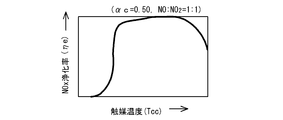
- the calculated ammonia amount An1 is expressed by the catalyst temperature Tcc of the selective reduction type NOx catalyst device 14 when the NO 2 ratio ⁇ c is 50% (NO: NO 2 is 1: 1) as shown in FIG.
- the ammonia amount An at this time is equal to the NO 2 ratio ⁇ c. 50%, that is, NO: NO 2 is not 1: 1, so the amount of NO 2 Vnc2 is expressed by the chemical reaction formula (3) “2NH 3 + NO + NO 2 ⁇ 2N 2 + 3H 2 O”
- An ammonia amount Ana is calculated based on the reaction and the NOx purification rate ⁇ e of FIG. Further, based on the reaction of the chemical reaction formula (2) “4NH 3 + 4NO + O 2 ⁇ 4N 2 + 6H 2 O” and the NOx purification rate ⁇ e of FIG. 7 with respect to the remaining NO (Vnc1 ⁇ Vnc2) in this reaction.
- the ammonia amount An at this time is equal to the NO 2 ratio ⁇ c. 50%, that is, NO: NO 2 is not 1: 1, so the reaction of the formula (3) “2NH 3 + NO + NO 2 ⁇ 2N 2 + 3H 2 O” of the chemical reaction formula for the amount of NOc Vnc1
- the ammonia amount Ana is calculated based on the NOx purification rate ⁇ e shown in FIG. Further, with respect to the amount of NO 2 remaining in this reaction (Vnc2 ⁇ Vnc1), the reaction of the chemical reaction formula (4) “8NH 3 + 6NO 2 ⁇ 7N 2 + 12H 2 O” and not shown in FIG.
- step S14 If it is determined in step S14 that ⁇ Vn ⁇ Vn2 is not satisfied (NO), it is determined that NO 2 is not adsorbed or released in the oxidation catalyst device 12, and the process goes to step S15 for the operation at equilibrium.
- step S15 it is determined whether or not the ratio (molar ratio) ⁇ 3 of NO 2 in NOx in the exhaust gas Ga flowing out from the oxidation catalyst device 12 is 50% or less. In other words, it is determined whether NO: NO 2 in the exhaust gas is 1: 1 or more.
- the NO amount Vna1 and the NO 2 amount Vna2 in the exhaust gas Ga flowing out from the oxidation catalyst device 12 are calculated.
- the first exhaust gas amount Vga passing through the oxidation catalyst device 12 is calculated.
- the first exhaust gas amount Vga refer to the relationship between the previously determined valve opening of the first flow control valve 11a, the valve opening of the second flow control valve 15a, the exhaust gas flow rate Vgt, and the first exhaust gas amount Vga. And obtained from both valve openings during control.
- the ratio ⁇ 2 of NO 2 to NOx in the exhaust gas Ga flowing into the oxidation catalyst device 12 (or the ratio of NO: NO 2 ) is set to the engine speed Ne indicating the operating state of the engine 10, the fuel injection amount Q, etc. From this, it is calculated with reference to the NO 2 ratio map data. Note that this NO 2 ratio map data is set in advance through experiments or the like and stored in the control device 30.
- the amount Vna3 of NO converted into NO 2 in the oxidation catalyst device 12 refers to the conversion rate map data indicating the relationship between the catalyst temperature Tca and the catalyst temperature Tca and the conversion rate (oxidation rate) ⁇ a from NO to NO 2 .
- the NO 2 amount Vna2 after passing through the oxidation catalyst device 12 is calculated.
- step S15 If it is determined in step S15 that the ratio (molar ratio) ⁇ 3 of NO 2 in NOx is 50% or less, that is, if NO: NO 2 in the exhaust gas is 1: 1 or more (NO / NO 2 > 1). (NO) Go to step S18.
- the entire amount Vgt of the exhaust gas Gt is caused to flow to the oxidation catalyst device 12, and the flow rate Vgb of the exhaust gas Gb passing through the bypass passage 15 is set to zero. That is, the first flow rate adjustment valve 11a is fully opened, and the second flow rate adjustment valve 15a is fully closed.
- the amount corresponding to the NO 2 amount Vna2 is expressed by the chemical reaction formula.
- the ammonia amount Ana is calculated based on the reaction of the expression “2NH 3 + NO + NO 2 ⁇ 2N 2 + 3H 2 O” and the NOx purification rate ⁇ e of FIG. Further, with respect to the remaining amount of NO (Vna1-Vna2) from this reaction, the reaction of the chemical reaction formula (2) “4NH 3 + 4NO + O 2 ⁇ 4N 2 + 6H 2 O” and the NOx purification rate ⁇ e of FIG.
- step S15 if the proportion ⁇ 3 of NO 2 in NOx is greater than 50% (YES), go to the flow rate adjustment of the exhaust gas in step S19 (Part 2).
- the first exhaust gas amount Vga passing through the oxidation catalyst device 12 and the ratio ⁇ 1 of NO 2 in the exhaust gas Ga exhausted from the oxidation catalyst device 12 are calculated.
- the first exhaust gas amount Vga refer to the relationship between the previously determined valve opening of the first flow control valve 11a, the valve opening of the second flow control valve 15a, the exhaust gas flow rate Vgt, and the first exhaust gas amount Vga. And obtained from both valve openings during control.
- the NO amount Vnb1 and the NO 2 amount Vnb2 in the exhaust gas Gb passing through the bypass passage 15 are calculated.
- the NO amount Vnb1 and the NO 2 amount Vnb2 are calculated from the exhaust gas flow rate Vgb, the NOx concentration Cn1, and the ratio ⁇ 2 of NO 2 to NOx in the exhaust gas Gt discharged from the engine 10.
- the ratio ⁇ c of the NO 2 amount is set to 50%, that is, the NO amount: NO 2 amount coincides with or approaches 1: 1. That is, based on the calculation result of the NO 2 ratio ⁇ c (or NO: NO 2 ) in NOx, the ratio ⁇ c of NO 2 flowing into the selective reduction type NOx catalyst device 14 is 50%, that is, NO: NO. Control is performed to adjust the first exhaust gas amount Vga and the second exhaust gas amount Vgb so that 2 becomes 1: 1.
- the ratio ⁇ c of NO 2 is 50%, that is, if NO: NO 2 is 1: 1, the chemical reaction formula (3) “2NH 3 + NO + NO 2 ⁇ 2N 2 + 3H 2 O” Based on this reaction, the ammonia amount An1 is calculated from the NOx amount (Vnc1 + Vnc2).
- the calculated ammonia amount An1 is expressed by the catalyst temperature Tcc of the selective reduction type NOx catalyst device 14 when the NO 2 ratio ⁇ c is 50% (NO: NO 2 is 1: 1) as shown in FIG.
- the ammonia amount at this time is such that the ratio ⁇ c of NO 2 is 50%, that is, if NO: NO 2 is not 1: 1, in other words, even if the exhaust gas flow rates Vga, Vgb are controlled,
- the ammonia amount Ana is calculated for the NO amount Vnc1.
- This ammonia amount Ana is calculated based on the reaction of the chemical reaction formula (3), “2NH 3 + NO + NO 2 ⁇ 2N 2 + 3H 2 O”, and the NOx purification rate ⁇ e of FIG.
- the amount of NO 2 remaining in this reaction (Vnc2-Vnc1) is a reaction of the chemical reaction formula (4), “8NH 3 + 6NO 2 ⁇ 7N 2 + 12H 2 O”, although not shown in FIG.
- step S20 the supply amount of the ammonia-based solution is controlled.
- an ammonia-based solution in an amount capable of generating the necessary ammonia amount An calculated in steps S16 to S19 is supplied from the injection valve 13a to the exhaust gas passage 11.
- step S16 to S19 the exhaust gas flow rate control in steps S16 to S19 and the ammonia solution supply amount control in step S20 are performed for a predetermined period of time (NO 2 adsorption amount increase / decrease determination interval and NO 2 ratio determination interval). Time) and return. After the return, steps S11 to S20 called from the advanced control flow are repeated.
- control flow of FIG. 2 is not called from the advanced control flow, and the control flow of FIG. If the operation of the engine 10 is terminated during the execution of the control flow of FIG. 2, an interrupt occurs, the control flow of FIG. 2 is interrupted, the control flow returns to the advanced control flow, and the advanced control flow ends. At the same time, the control flow of FIG.
- step S17 and step S19 the ratio ⁇ c of the NO 2 amount in NOx in the exhaust gas Gc flowing into the selective reduction type NOx catalyst device 14 is set to 50% (NO amount: Since the NO 2 amount matches or approaches 1: 1), NOx purification performance can be improved.
- NO amount Since the NO 2 amount matches or approaches 1: 1), NOx purification performance can be improved. The reason is as follows.
- the NO 2 adsorption amount Vn of the oxidation catalyst device 12 is small and has not reached saturation, the NO 2 generated in the oxidation catalyst device 12 is oxidized. NOx that is adsorbed by the NOx and flows into the selective reduction type NOx catalyst device 14 becomes almost NO.
- the supply amount of the ammonia-based solution is changed to a reaction formula (4) “4NH in which NOx purification is NO. 3 + 4NO + O 2 ⁇ 4N 2 + 6H 2 O ”is calculated based on the NOx purification rate map of the selective reduction type NOx catalyst, and a necessary amount Lc of the ammonia-based solution is added. it can.
- the conversion rate NO from NO to NO 2 predicted from the exhaust gas flow rate Vga, the catalyst temperature Tca, the NOx concentration Cn1, and the oxygen concentration Co
- NO NO corresponding to 2 production rate NO corresponding to 2 production rate
- circulating oxidation catalyst device 12 first The first exhaust gas flow rate Vga and the second exhaust gas flow rate Vgb that does not flow through the oxidation catalyst device 12 are adjusted so that NO: NO 2 flowing into the selective reduction type NOx catalyst device 14 becomes 1: 1.
- the NO 2 adsorption amount of the oxidation catalyst device 12 has reached saturation, and it is determined that desorption of adsorbed NO 2 occurs as the NO 2 saturation adsorption amount Vnf decreases due to an increase in the catalyst temperature Tca of the oxidation catalyst.
- the NOx desorption amount Vna5 is estimated from the degree of temperature rise.
- the NOx emission amount Vn1 from the engine 10 and the conversion rate ⁇ a from NO to NO 2 are obtained from the exhaust gas conditions at that time, and the NO 2 amount including the desorbed NO 2 is estimated.
- the first exhaust gas amount Vga and the second exhaust gas amount Vgb that is not allowed to pass through are adjusted. Further, the supply amount Lc corresponding to the NOx amount Vnc purified under the exhaust gas conditions at that time can be added to the ammonia-based solution.
- the selective reduction type NOx it is determined whether or not the NO 2 adsorption of the oxidation catalyst device 12 has reached saturation, and the result is taken into consideration, whereby the selective reduction type NOx.
- the ratio ⁇ c of NO 2 to NOx flowing into the catalyst device 14 (or the ratio of NO: NO 2 ) can be estimated, and the purification performance of the selective reduction type NOx catalyst due to the difference in the components of NOx can be reflected better.
- the NOx purification system control method and NOx purification system of the present invention having the excellent effects described above estimate the NO 2 adsorption state of the oxidation catalyst device and NO: NO 2 of NOx flowing into the selective reduction type NOx catalyst device. As close as possible to 1: 1, the required amount of ammonia solution can be added to avoid problems caused by insufficient or excessive supply of ammonia.
- the present invention can be used extremely effectively for a NOx purification system that includes a type NOx catalyst device and reduces NOx in exhaust gas.
Abstract
Description
10 ディーゼルエンジン
11 排気ガス通路
11a 第1流量調整弁
12 酸化触媒装置(DOC)
13 アンモニア系溶液供給装置
13a 噴射弁
14 選択還元型NOx触媒装置(SCR)
15 バイパス通路
15a 第2流量調整弁
16 第1排気ガス温度センサ
17 第2排気ガス温度センサ
18 第3排気ガス温度センサ
19 第1NOx濃度センサ
20 第2NOx濃度センサ
21 酸素濃度センサ
22 エンジン運転状態検出装置
30 制御装置(ECU)
30a 供給量制御装置
An、An1、Ana、Anb、Anc アンモニア量
Cn1 第1NOx濃度
Cn2 第2NOx濃度
Co 酸素濃度
Ga 酸化触媒装置を通過する排気ガス
Gb バイパス通路を通過する排気ガス
Gc 選択還元型NOx触媒装置に流入する排気ガス
Gt エンジンから排出された排気ガス
Lc アンモニア系溶液の供給量
Ne エンジン回転数
Q 燃料噴射量(又は負荷)
Tca 触媒温度
Tcc 選択還元型触媒装置の触媒温度
Va 吸気量
Vga 第1排気ガス流量
Vgb 第2排気ガス流量
Vn NO2吸着量
Vn1 酸化触媒装置に流入するNOx量
Vn2 酸化触媒装置から流出するNOx量
Vna、Vnai、Vnb、Vnc NOx量
Vna1、Vnai1、Vnb1、Vnc1 NO量
Vna2、Vna4、Vna5、Vnai2、Vnb2、Vnc2 NO2量
Vna3 酸化触媒装置でNOがNO2に変換される量
Vnc 選択還元型NOx触媒装置に流入するNOx量
Vnf NO2飽和吸着量
Vnt エンジンから流出するNOx量
α1 酸化触媒装置から排出される排気ガス中のNOxに対するNO2の割合
α2 バイパス通路の排気ガス中のNO2の割合
αc 選択還元型NOx触媒装置に流入する排気ガス中のNOxに対するNO2の割合
βa NOからNO2への変換率(酸化率)
ηe NOx浄化率
ΔVn NO2吸着量の増減量
ΔVn1 所定の第1判定値
ΔVn2 所定の第2判定値
ΔCn1 所定の第1判定濃度
ΔCn2 所定の第2判定濃度 DESCRIPTION OF
13 Ammonia
DESCRIPTION OF
30a Supply amount control device An, An1, Ana, Anb, Anc Ammonia amount Cn1 First NOx concentration Cn2 Second NOx concentration Co Oxygen concentration Ga Exhaust gas passing through oxidation catalyst device Gb Exhaust gas passing through bypass passage Gc Selective reduction type NOx catalyst Exhaust gas flowing into the system Gt Exhaust gas discharged from the engine Lc Ammonia-based solution supply amount Ne Engine speed Q Fuel injection amount (or load)
Tca catalyst temperature Tcc catalyst temperature of selective reduction type catalyst device Va intake amount Vga first exhaust gas flow rate Vgb second exhaust gas flow rate Vn NO 2 adsorption amount Vn1 NOx amount flowing into oxidation catalyst device Vn2 NOx amount flowing out from oxidation catalyst device Vna, Vnai, Vnb, Vnc NOx amount Vna1, Vnai1, Vnb1, Vnc1 NO amount Vna2, Vna4, Vna5, Vnai2, Vnb2, Vnc2 NO 2 amount Vna3 amount Vnc selective reduction of NO in the oxidation catalyst device is converted to NO 2 the NOx amount Vnf NO 2 saturation adsorption amount Vnt NO 2 in the exhaust gas in proportion α2 bypass passage NO 2 for NOx in the exhaust gas discharged from the NOx amount α1 oxidation catalyst device to flow out from the engine flowing into the NOx catalyst device Ratio αc Selective reduction type NOx catalyst device Ratio of NO 2 to NOx in inflowing exhaust gas βa Conversion rate from NO to NO 2 (oxidation rate)
ηe NOx purification rate ΔVn NO 2 adsorption amount increase / decrease amount ΔVn1 predetermined first determination value ΔVn2 predetermined second determination value ΔCn1 predetermined first determination concentration ΔCn2 predetermined second determination concentration
ン10直後の排気ガス通路11に設けられる。 A first
濃度Co(排気ガスGtの酸素濃度Coと同じ)から、それに対応するNOとNO2の平衡組成(NO:NO2平衡比)データを参照して、触媒温度Tcaと酸素濃度CoによるNOとNO2の平衡組成に応じて推定する。このNOとNO2の平衡組成データは、例えば、図4と図5に例示するようなものである。この図4と図5では、横軸が触媒温度Tcaを示し、縦軸がNO2の割合α1を示す。線はNOとNO2の平衡組成を示す。図4は、酸素濃度Coが10%の場合を示し、図5は、酸素濃度Coが2%の場合を示す。従って、例えば、排気ガスGの酸素濃度Coが10%の場合は図4を参照し、触媒温度Tcaが400℃であれば、NO2の割合α1は約60%となる。このようにして、酸化触媒装置12から流出する排気ガスGaにおけるNOx中のNO2の割合α1を推定する。 The ratio α1 of NO 2 is obtained from the catalyst composition Tca of the
、ステップS18に行く。ステップS18のバイパス通路の閉鎖(その2)の制御では、排気ガスGtの全量Vgtを酸化触媒装置12に流し、バイパス通路15を通過する排気ガスGbの流量Vgbをゼロとする。即ち、第1流量調整弁11aを全開とし、第2流量調整弁15aを全閉とする。 If it is determined in step S15 that the ratio (molar ratio) α3 of NO 2 in NOx is 50% or less, that is, if NO: NO 2 in the exhaust gas is 1: 1 or more (NO / NO 2 > 1). (NO)
Go to step S18. In the control of the bypass passage closing (part 2) in step S18, the entire amount Vgt of the exhaust gas Gt is caused to flow to the
Claims (8)
- 排気ガス通路に上流側から順に、酸化触媒装置と、排気ガス通路にアンモニア系溶液を供給するアンモニア系溶液供給装置と、選択還元型NOx触媒装置と、前記酸化触媒装置の上流側で前記排気ガス通路から分岐して前記アンモニア系溶液供給装置の上流で前記排気ガス通路に合流するバイパス流路と、該バイパス通路を流れる排気ガスの流量を調整する排気ガス流量調整装置を備えると共に、前記アンモニア系溶液の供給量を制御する制御装置を備えて、排気ガス中のNOxを還元するNOx浄化システムの制御方法において、 前記酸化触媒装置におけるNO2吸着量の増減を、前記酸化触媒装置の前後のNOx量から推定し、この推定したNO2吸着量の増減に基づいて、前記酸化触媒装置を通過する排気ガスの流量と前記バイパス通路を通過する排気ガスの流量を調整することを特徴とする排気ガス浄化システムの制御方法。 In order from the upstream side to the exhaust gas passage, the oxidation catalyst device, the ammonia-based solution supply device for supplying the ammonia-based solution to the exhaust gas passage, the selective reduction type NOx catalyst device, and the exhaust gas upstream of the oxidation catalyst device A bypass passage that branches off from the passage and joins the exhaust gas passage upstream of the ammonia-based solution supply device; an exhaust gas flow adjustment device that adjusts the flow rate of the exhaust gas flowing through the bypass passage; In a control method of a NOx purification system comprising a control device for controlling the supply amount of a solution and reducing NOx in exhaust gas, the increase or decrease in the NO 2 adsorption amount in the oxidation catalyst device is determined by the NOx before and after the oxidation catalyst device. estimated from the amount, based on the increase or decrease of the estimated NO 2 adsorption amount, the bypass passage and the flow rate of the exhaust gas passing through the oxidation catalyst device Method for controlling an exhaust gas purification system, characterized by adjusting the flow rate of the exhaust gas passing through the.
- 前記推定したNO2吸着量が増加している場合には、前記バイパス通路を通過する排気ガスの流量をゼロとし、
前記推定したNO2吸着量が減少している場合には、排気ガスの一部を前記バイパス通路を通過させると共に、排気ガスの残りの部分を前記酸化触媒装置を通過させ、
前記推定したNO2吸着量の増減が無い場合には、前記酸化触媒装置から出る排気ガス中のNOx中のNO2の割合(モル比)を推定し、
この推定されたNO2の割合が50%以下では、排気ガスの全量を前記酸化触媒装置を通過させ、
この推定されたNO2の割合が50%より大きい場合には、排気ガスの一部を前記バイパス通路を通過させると共に、排気ガスの残りの部分を前記酸化触媒装置を通過させることを特徴とする請求項1記載のNOx浄化システムの制御方法。 When the estimated NO 2 adsorption amount is increased, the flow rate of the exhaust gas passing through the bypass passage is set to zero,
When the estimated NO 2 adsorption amount decreases, a part of the exhaust gas passes through the bypass passage, and the remaining part of the exhaust gas passes through the oxidation catalyst device,
When there is no increase / decrease in the estimated NO 2 adsorption amount, the ratio (molar ratio) of NO 2 in NOx in the exhaust gas emitted from the oxidation catalyst device is estimated,
When the estimated ratio of NO 2 is 50% or less, the entire amount of exhaust gas is allowed to pass through the oxidation catalyst device,
When the estimated ratio of NO 2 is larger than 50%, a part of the exhaust gas is allowed to pass through the bypass passage, and the remaining part of the exhaust gas is allowed to pass through the oxidation catalyst device. The control method of the NOx purification system according to claim 1. - 前記の排気ガスの一部を前記バイパス通路を通過させると共に、排気ガスの残りの部分を前記酸化触媒装置を通過させるときに、前記選択還元型NOx触媒装置に流入するNO2の割合が50%になるように、前記バイパス通路を通過させる排気ガスの量を調整することを特徴とする請求項2記載のNOx浄化システムの制御方法。 When a part of the exhaust gas passes through the bypass passage and the remaining part of the exhaust gas passes through the oxidation catalyst device, the ratio of NO 2 flowing into the selective reduction NOx catalyst device is 50%. The control method of the NOx purification system according to claim 2, wherein the amount of exhaust gas that passes through the bypass passage is adjusted so as to become.
- 前記推定したNO2吸着量が減少している場合に、前記選択還元型NOx装置に流入する排気ガス中のNO2の割合を推定する際に、前記酸化触媒装置の温度と排気ガスの酸素濃度によるNOとNO2の平衡組成状態に基づいて、前記酸化触媒装置から出る排気ガス中のNO2の割合を推定することを特徴とする請求項2又は3記載のNOx浄化システムの制御方法。 When estimating the ratio of NO 2 in the exhaust gas flowing into the selective reduction NOx device when the estimated NO 2 adsorption amount is decreasing, the temperature of the oxidation catalyst device and the oxygen concentration of the exhaust gas are estimated. based on the equilibrium composition state of the NO and NO 2 by the control method according to claim 2 or 3, wherein the NOx purification system and estimates the proportion of NO 2 in the exhaust gas exiting the oxidation catalyst device.
- 排気ガス通路に上流側から順に、酸化触媒装置と、排気ガス通路にアンモニア系溶液を供給するアンモニア系溶液供給装置と、選択還元型NOx触媒装置と、前記酸化触媒装置の上流側で前記排気ガス通路から分岐して前記アンモニア系溶液供給装置の上流で前記排気ガス通路に合流するバイパス流路と、該バイパス通路を流れる排気ガスの流量を調整する排気ガス流量調整装置を備えると共に、前記アンモニア系溶液の供給量を制御する制御装置を備えて、排気ガス中のNOxを還元するNOx浄化システムにおいて、
前記制御装置が、前記酸化触媒装置におけるNO2吸着量の増減を、前記酸化触媒装置の前後のNOx量から推定し、この推定したNO2吸着量の増減に基づいて、前記酸化触媒装置を通過する排気ガスの流量と前記バイパス通路を通過する排気ガスの流量を調整することを特徴とする排気ガス浄化システム。 In order from the upstream side to the exhaust gas passage, the oxidation catalyst device, the ammonia-based solution supply device for supplying the ammonia-based solution to the exhaust gas passage, the selective reduction type NOx catalyst device, and the exhaust gas upstream of the oxidation catalyst device A bypass passage that branches off from the passage and joins the exhaust gas passage upstream of the ammonia-based solution supply device; an exhaust gas flow adjustment device that adjusts the flow rate of the exhaust gas flowing through the bypass passage; In a NOx purification system that includes a control device that controls the supply amount of a solution and reduces NOx in exhaust gas,
The control device estimates the increase or decrease in the NO 2 adsorption amount in the oxidation catalyst device from the NOx amount before and after the oxidation catalyst device, and passes through the oxidation catalyst device based on the estimated increase or decrease in the NO 2 adsorption amount. An exhaust gas purification system that adjusts the flow rate of exhaust gas that flows and the flow rate of exhaust gas that passes through the bypass passage. - 前記制御装置が、
前記推定したNO2吸着量が増加している場合には、前記バイパス通路を通過する排気ガスの流量をゼロとする制御を行い、
前記推定したNO2吸着量が減少している場合には、排気ガスの一部を前記バイパス通路を通過させると共に、排気ガスの残りの部分を前記酸化触媒装置を通過させる制御を行い、
前記推定したNO2吸着量の増減が無い場合には、前記酸化触媒装置から出る排気ガス中のNOx中のNO2の割合(モル比)を推定し、
この推定されたNO2の割合が50%以下では、排気ガスの全量を前記酸化触媒装置を通過させる制御を行い、
この推定されたNO2の割合が50%より大きい場合には、排気ガスの一部を前記バイパス通路を通過させると共に、排気ガスの残りの部分を前記酸化触媒装置を通過させる制御を行うことを特徴とする請求項5記載のNOx浄化システム。 The control device is
When the estimated NO 2 adsorption amount is increased, control is performed to make the flow rate of the exhaust gas passing through the bypass passage zero,
When the estimated NO 2 adsorption amount is decreasing, a control is performed to pass a part of the exhaust gas through the bypass passage and the remaining part of the exhaust gas through the oxidation catalyst device,
When there is no increase / decrease in the estimated NO 2 adsorption amount, the ratio (molar ratio) of NO 2 in NOx in the exhaust gas emitted from the oxidation catalyst device is estimated,
When the estimated ratio of NO 2 is 50% or less, control is performed to pass the entire amount of exhaust gas through the oxidation catalyst device,
When the estimated ratio of NO 2 is larger than 50%, control is performed to pass a part of the exhaust gas through the bypass passage and to pass the remaining part of the exhaust gas through the oxidation catalyst device. The NOx purification system according to claim 5, wherein - 前記制御装置が、
前記の排気ガスの一部を前記バイパス通路を通過させると共に、排気ガスの残りの部分を前記酸化触媒装置を通過させるときに、前記選択還元型NOx触媒装置に流入するNO2の割合が50%になるように、前記バイパス通路を通過させる排気ガスの量を調整する制御を行うことを特徴とする請求項6記載のNOx浄化システム。 The control device is
When a part of the exhaust gas passes through the bypass passage and the remaining part of the exhaust gas passes through the oxidation catalyst device, the ratio of NO 2 flowing into the selective reduction NOx catalyst device is 50%. The NOx purification system according to claim 6, wherein control is performed to adjust the amount of exhaust gas that passes through the bypass passage. - 前記制御装置が、
前記推定したNO2吸着量が減少している場合に、前記選択還元型NOx装置に流入する排気ガス中のNO2の割合を推定する際に、前記酸化触媒装置の温度と排気ガスの酸素濃度によるNOとNO2の平衡組成状態に基づいて、前記酸化触媒装置から出る排気ガス中のNO2の割合を推定することを特徴とする請求項6又は7記載のNOx浄化システム。 The control device is
When estimating the ratio of NO 2 in the exhaust gas flowing into the selective reduction NOx device when the estimated NO 2 adsorption amount is decreasing, the temperature of the oxidation catalyst device and the oxygen concentration of the exhaust gas are estimated. 8. The NOx purification system according to claim 6, wherein the ratio of NO 2 in the exhaust gas emitted from the oxidation catalyst device is estimated on the basis of an equilibrium composition state of NO and NO 2 produced by NO.
Priority Applications (4)
| Application Number | Priority Date | Filing Date | Title |
|---|---|---|---|
| CN2008801278958A CN101965440B (en) | 2008-03-11 | 2008-11-27 | Method of controlling nox purification system, and nox purification system |
| US12/736,090 US8464517B2 (en) | 2008-03-11 | 2008-11-27 | Method of controlling NOx purification system, and NOx purification system |
| EP08873259.9A EP2261477B1 (en) | 2008-03-11 | 2008-11-27 | Method of controlling nox purification system, and nox purification system |
| AU2008352471A AU2008352471B2 (en) | 2008-03-11 | 2008-11-27 | Method of controlling NOx purification system, and NOx purification system |
Applications Claiming Priority (2)
| Application Number | Priority Date | Filing Date | Title |
|---|---|---|---|
| JP2008061879A JP5272455B2 (en) | 2008-03-11 | 2008-03-11 | NOx purification system control method and NOx purification system |
| JP2008-061879 | 2008-03-11 |
Publications (1)
| Publication Number | Publication Date |
|---|---|
| WO2009113211A1 true WO2009113211A1 (en) | 2009-09-17 |
Family
ID=41064885
Family Applications (1)
| Application Number | Title | Priority Date | Filing Date |
|---|---|---|---|
| PCT/JP2008/071501 WO2009113211A1 (en) | 2008-03-11 | 2008-11-27 | Method of controlling nox purification system, and nox purification system |
Country Status (6)
| Country | Link |
|---|---|
| US (1) | US8464517B2 (en) |
| EP (1) | EP2261477B1 (en) |
| JP (1) | JP5272455B2 (en) |
| CN (1) | CN101965440B (en) |
| AU (1) | AU2008352471B2 (en) |
| WO (1) | WO2009113211A1 (en) |
Families Citing this family (24)
| Publication number | Priority date | Publication date | Assignee | Title |
|---|---|---|---|---|
| DE102009029257B3 (en) * | 2009-09-08 | 2010-10-28 | Ford Global Technologies, LLC, Dearborn | Method for identification of deviations of fuel or airflow rate in internal combustion engine, involves determining nitrogen oxide extremes based on measured exhaust gas lambda value |
| JP5198520B2 (en) * | 2010-08-25 | 2013-05-15 | 本田技研工業株式会社 | Exhaust gas purification system for internal combustion engine |
| US8720189B2 (en) * | 2011-01-26 | 2014-05-13 | GM Global Technology Operations LLC | Apparatus and method for onboard performance monitoring of oxidation catalyst |
| EP2693036A4 (en) * | 2011-03-31 | 2015-09-30 | Mitsubishi Heavy Ind Ltd | Gas engine control device |
| JP5284408B2 (en) * | 2011-04-05 | 2013-09-11 | 本田技研工業株式会社 | Exhaust gas purification system for internal combustion engine |
| JP5864901B2 (en) * | 2011-05-19 | 2016-02-17 | 日野自動車株式会社 | Manual regeneration of particulate filter |
| DE102011106441A1 (en) | 2011-07-04 | 2013-01-10 | Clausthaler Umwelttechnik-Institut Gmbh (Cutec-Institut) | Process for low nitrogen oxide oxidation of fuel-nitrogen compounds and devices therefor |
| US20130047583A1 (en) * | 2011-08-31 | 2013-02-28 | Caterpillar Inc. | Aftertreatment system |
| US8800267B2 (en) * | 2012-01-31 | 2014-08-12 | GM Global Technology Operations LLC | Control system for modulating an air mass |
| US8635862B2 (en) * | 2012-03-13 | 2014-01-28 | GM Global Technology Operations LLC | Control system for reducing nitrous oxide (“N2O”) after selective catalytic reduction (“SCR”) device light-off |
| EP2894305B1 (en) * | 2012-09-03 | 2017-05-17 | Toyota Jidosha Kabushiki Kaisha | Exhaust gas purification system for an internal combustion engine |
| JP6287539B2 (en) * | 2014-04-24 | 2018-03-07 | いすゞ自動車株式会社 | Exhaust purification system |
| DE102015211169A1 (en) * | 2015-06-17 | 2016-12-22 | Mtu Friedrichshafen Gmbh | A method of operating an exhaust aftertreatment system, exhaust aftertreatment system, and internal combustion engine having an exhaust aftertreatment system |
| CN106799123B (en) * | 2017-02-22 | 2019-10-11 | 上海龙净环保科技工程有限公司 | A kind of control method and its control device of denitrification apparatus ammonia spraying amount |
| US10551261B2 (en) * | 2017-02-28 | 2020-02-04 | Rosemount Inc. | Joint for brittle materials |
| US10215072B2 (en) * | 2017-03-23 | 2019-02-26 | GM Global Technology Operations LLC | Methods for controlling and detecting catalyst poisoning of selective catalytic reduction devices |
| CN114191980A (en) * | 2017-04-26 | 2022-03-18 | 托普索公司 | Method and system for removing particulate matter and harmful compounds from flue gas |
| SG11201909080XA (en) * | 2017-04-26 | 2019-11-28 | Haldor Topsoe As | Method and system for the removal of noxious compounds from flue-gas using an scr catalyst |
| WO2018197176A1 (en) | 2017-04-26 | 2018-11-01 | Haldor Topsøe A/S | Method and system for the removal of noxious compounds from flue-gas using fabric filter bags with an scr catalyst |
| JP2018189056A (en) * | 2017-05-10 | 2018-11-29 | トヨタ自動車株式会社 | Exhaust emission control device for internal combustion engine |
| FR3071871B1 (en) * | 2017-09-29 | 2020-02-07 | Continental Automotive France | SELECTIVE CATALYTIC REDUCTION PROCESS WITH AMMONIA DESORPTION FROM A CARTRIDGE IN AN EXHAUST LINE |
| EP3628835A1 (en) * | 2018-09-28 | 2020-04-01 | Winterthur Gas & Diesel Ltd. | Exhaust gas aftertreatment system |
| CN113828152A (en) * | 2021-10-15 | 2021-12-24 | 中国船舶工业集团公司第七0八研究所 | Low-temperature SCR device and method for marine low-sulfur fuel oil |
| CN115501908B (en) * | 2022-09-13 | 2023-11-03 | 东风商用车有限公司 | Has low temperature NO x Sulfur-resistant SCR catalyst with adsorption function and application thereof |
Citations (7)
| Publication number | Priority date | Publication date | Assignee | Title |
|---|---|---|---|---|
| JPH1071325A (en) * | 1996-06-21 | 1998-03-17 | Ngk Insulators Ltd | Method for controlling engine exhaust gas system and method for detecting deterioration in catalyst/ adsorption means |
| JP2003236343A (en) * | 2002-02-12 | 2003-08-26 | Babcock Hitachi Kk | Method for decontaminating exhaust gas and apparatus for denitration at low temperature |
| JP2005023921A (en) * | 2003-06-12 | 2005-01-27 | Hino Motors Ltd | Exhaust emission control device |
| JP2007023872A (en) * | 2005-07-15 | 2007-02-01 | Nissan Diesel Motor Co Ltd | Exhaust emission control device |
| JP2007100510A (en) * | 2005-09-30 | 2007-04-19 | Bosch Corp | Exhaust emission control device of internal combustion engine, and exhaust emission control method for internal combustion engine |
| JP2007130580A (en) * | 2005-11-10 | 2007-05-31 | Toyota Motor Corp | Apparatus and method of purifying exhaust gas |
| JP2007154819A (en) | 2005-12-07 | 2007-06-21 | Toyota Central Res & Dev Lab Inc | Exhaust emission control device and exhaust emission control method using the same |
Family Cites Families (6)
| Publication number | Priority date | Publication date | Assignee | Title |
|---|---|---|---|---|
| US6399034B1 (en) * | 1997-05-14 | 2002-06-04 | Hjs Fahrzeugtechnik Gmbh & Co. | Process for reducing nitrogen oxides on SCR catalyst |
| JP2005002968A (en) * | 2003-06-16 | 2005-01-06 | Mitsubishi Fuso Truck & Bus Corp | Exhaust emission control device of internal combustion engine |
| DE102004036036A1 (en) * | 2004-07-24 | 2006-03-16 | Daimlerchrysler Ag | Exhaust system, in particular for an internal combustion engine of a motor vehicle |
| WO2008103113A1 (en) * | 2007-02-21 | 2008-08-28 | Volvo Lastvagnar Ab | On-board-diagnosis method for an exhaust aftertreatment system and on-board-diagnosis system for an exhaust aftertreatment system |
| WO2008135805A1 (en) * | 2007-05-02 | 2008-11-13 | Perkins Engines Company Limited | Exhaust treatment system implementing selective doc bypass |
| US20080295499A1 (en) * | 2007-05-31 | 2008-12-04 | James Joshua Driscoll | Exhaust system utilizing a low-temperature oxidation catalyst |
-
2008
- 2008-03-11 JP JP2008061879A patent/JP5272455B2/en not_active Expired - Fee Related
- 2008-11-27 EP EP08873259.9A patent/EP2261477B1/en active Active
- 2008-11-27 US US12/736,090 patent/US8464517B2/en active Active
- 2008-11-27 WO PCT/JP2008/071501 patent/WO2009113211A1/en active Application Filing
- 2008-11-27 CN CN2008801278958A patent/CN101965440B/en not_active Expired - Fee Related
- 2008-11-27 AU AU2008352471A patent/AU2008352471B2/en not_active Ceased
Patent Citations (7)
| Publication number | Priority date | Publication date | Assignee | Title |
|---|---|---|---|---|
| JPH1071325A (en) * | 1996-06-21 | 1998-03-17 | Ngk Insulators Ltd | Method for controlling engine exhaust gas system and method for detecting deterioration in catalyst/ adsorption means |
| JP2003236343A (en) * | 2002-02-12 | 2003-08-26 | Babcock Hitachi Kk | Method for decontaminating exhaust gas and apparatus for denitration at low temperature |
| JP2005023921A (en) * | 2003-06-12 | 2005-01-27 | Hino Motors Ltd | Exhaust emission control device |
| JP2007023872A (en) * | 2005-07-15 | 2007-02-01 | Nissan Diesel Motor Co Ltd | Exhaust emission control device |
| JP2007100510A (en) * | 2005-09-30 | 2007-04-19 | Bosch Corp | Exhaust emission control device of internal combustion engine, and exhaust emission control method for internal combustion engine |
| JP2007130580A (en) * | 2005-11-10 | 2007-05-31 | Toyota Motor Corp | Apparatus and method of purifying exhaust gas |
| JP2007154819A (en) | 2005-12-07 | 2007-06-21 | Toyota Central Res & Dev Lab Inc | Exhaust emission control device and exhaust emission control method using the same |
Also Published As
| Publication number | Publication date |
|---|---|
| EP2261477B1 (en) | 2020-11-04 |
| AU2008352471A1 (en) | 2009-09-17 |
| US8464517B2 (en) | 2013-06-18 |
| JP2009216019A (en) | 2009-09-24 |
| US20110041481A1 (en) | 2011-02-24 |
| EP2261477A4 (en) | 2015-08-26 |
| JP5272455B2 (en) | 2013-08-28 |
| EP2261477A1 (en) | 2010-12-15 |
| CN101965440A (en) | 2011-02-02 |
| CN101965440B (en) | 2013-03-27 |
| AU2008352471B2 (en) | 2012-01-12 |
Similar Documents
| Publication | Publication Date | Title |
|---|---|---|
| JP5272455B2 (en) | NOx purification system control method and NOx purification system | |
| US7858060B2 (en) | Current storage estimation for selective catalytic reduction catalysts | |
| US8713916B2 (en) | NOx purification system and method for control of NOx purification system | |
| US8356470B2 (en) | Method of controlling NOx purification system and NOx purification system | |
| US20100028230A1 (en) | Dosing agent injection control for selective catalytic reduction catalysts | |
| JP4715581B2 (en) | Exhaust gas purification system control method and exhaust gas purification system | |
| JP4179386B2 (en) | NOx purification system and control method of NOx purification system | |
| US8978367B2 (en) | Exhaust gas purifying system of internal combustion engine | |
| JP5127052B2 (en) | Exhaust treatment device control device | |
| JP2005002968A (en) | Exhaust emission control device of internal combustion engine | |
| JP5398372B2 (en) | Engine exhaust purification system | |
| JP2012017674A (en) | Exhaust gas purification apparatus of internal combustion engine | |
| JP2011196311A (en) | Exhaust emission purifying method and exhaust emission purifying apparatus | |
| JP2005023921A (en) | Exhaust emission control device | |
| US8263031B2 (en) | Method for purifying exhaust gas and system therefor | |
| JP2009293605A (en) | Control device for exhaust treatment device | |
| JP2011241686A (en) | Exhaust emission control device of internal combustion engine | |
| JP2012031787A (en) | Device and method for exhaust emission control of internal combustion engine | |
| CN113544365A (en) | Method for regulating the loading of a particle filter | |
| JP2017031942A (en) | Exhaust emission control system for internal combustion engine, internal combustion engine and exhaust emission control method for internal combustion engine | |
| KR100999611B1 (en) | Method for calculating ammonia storage amount | |
| JP4267538B2 (en) | Exhaust purification equipment | |
| JP7310730B2 (en) | Purification control device | |
| JP5476770B2 (en) | Exhaust gas purification system and control method of exhaust gas purification system | |
| KR20050080532A (en) | Control method of scr |
Legal Events
| Date | Code | Title | Description |
|---|---|---|---|
| WWE | Wipo information: entry into national phase |
Ref document number: 200880127895.8 Country of ref document: CN |
|
| 121 | Ep: the epo has been informed by wipo that ep was designated in this application |
Ref document number: 08873259 Country of ref document: EP Kind code of ref document: A1 |
|
| WWE | Wipo information: entry into national phase |
Ref document number: 2008352471 Country of ref document: AU |
|
| NENP | Non-entry into the national phase |
Ref country code: DE |
|
| WWE | Wipo information: entry into national phase |
Ref document number: 2008873259 Country of ref document: EP |
|
| ENP | Entry into the national phase |
Ref document number: 2008352471 Country of ref document: AU Date of ref document: 20081127 Kind code of ref document: A |
|
| WWE | Wipo information: entry into national phase |
Ref document number: 12736090 Country of ref document: US |