WO2009107789A1 - Cutting insert for drill, drill, and cutting method using same - Google Patents
Cutting insert for drill, drill, and cutting method using same Download PDFInfo
- Publication number
- WO2009107789A1 WO2009107789A1 PCT/JP2009/053709 JP2009053709W WO2009107789A1 WO 2009107789 A1 WO2009107789 A1 WO 2009107789A1 JP 2009053709 W JP2009053709 W JP 2009053709W WO 2009107789 A1 WO2009107789 A1 WO 2009107789A1
- Authority
- WO
- WIPO (PCT)
- Prior art keywords
- region
- insert
- drill
- cutting
- holder
- Prior art date
Links
Images


Classifications
-
- B—PERFORMING OPERATIONS; TRANSPORTING
- B23—MACHINE TOOLS; METAL-WORKING NOT OTHERWISE PROVIDED FOR
- B23B—TURNING; BORING
- B23B51/00—Tools for drilling machines
-
- B—PERFORMING OPERATIONS; TRANSPORTING
- B23—MACHINE TOOLS; METAL-WORKING NOT OTHERWISE PROVIDED FOR
- B23B—TURNING; BORING
- B23B27/00—Tools for turning or boring machines; Tools of a similar kind in general; Accessories therefor
- B23B27/14—Cutting tools of which the bits or tips or cutting inserts are of special material
- B23B27/141—Specially shaped plate-like cutting inserts, i.e. length greater or equal to width, width greater than or equal to thickness
-
- B—PERFORMING OPERATIONS; TRANSPORTING
- B23—MACHINE TOOLS; METAL-WORKING NOT OTHERWISE PROVIDED FOR
- B23B—TURNING; BORING
- B23B2200/00—Details of cutting inserts
- B23B2200/08—Rake or top surfaces
-
- B—PERFORMING OPERATIONS; TRANSPORTING
- B23—MACHINE TOOLS; METAL-WORKING NOT OTHERWISE PROVIDED FOR
- B23B—TURNING; BORING
- B23B2200/00—Details of cutting inserts
- B23B2200/08—Rake or top surfaces
- B23B2200/086—Rake or top surfaces with one or more grooves
- B23B2200/087—Rake or top surfaces with one or more grooves for chip breaking
-
- B—PERFORMING OPERATIONS; TRANSPORTING
- B23—MACHINE TOOLS; METAL-WORKING NOT OTHERWISE PROVIDED FOR
- B23B—TURNING; BORING
- B23B2200/00—Details of cutting inserts
- B23B2200/12—Side or flank surfaces
- B23B2200/125—Side or flank surfaces discontinuous
-
- B—PERFORMING OPERATIONS; TRANSPORTING
- B23—MACHINE TOOLS; METAL-WORKING NOT OTHERWISE PROVIDED FOR
- B23B—TURNING; BORING
- B23B2205/00—Fixation of cutting inserts in holders
- B23B2205/12—Seats for cutting inserts
-
- B—PERFORMING OPERATIONS; TRANSPORTING
- B23—MACHINE TOOLS; METAL-WORKING NOT OTHERWISE PROVIDED FOR
- B23B—TURNING; BORING
- B23B2251/00—Details of tools for drilling machines
- B23B2251/50—Drilling tools comprising cutting inserts
-
- Y—GENERAL TAGGING OF NEW TECHNOLOGICAL DEVELOPMENTS; GENERAL TAGGING OF CROSS-SECTIONAL TECHNOLOGIES SPANNING OVER SEVERAL SECTIONS OF THE IPC; TECHNICAL SUBJECTS COVERED BY FORMER USPC CROSS-REFERENCE ART COLLECTIONS [XRACs] AND DIGESTS
- Y10—TECHNICAL SUBJECTS COVERED BY FORMER USPC
- Y10T—TECHNICAL SUBJECTS COVERED BY FORMER US CLASSIFICATION
- Y10T407/00—Cutters, for shaping
- Y10T407/19—Rotary cutting tool
- Y10T407/1906—Rotary cutting tool including holder [i.e., head] having seat for inserted tool
- Y10T407/1908—Face or end mill
-
- Y—GENERAL TAGGING OF NEW TECHNOLOGICAL DEVELOPMENTS; GENERAL TAGGING OF CROSS-SECTIONAL TECHNOLOGIES SPANNING OVER SEVERAL SECTIONS OF THE IPC; TECHNICAL SUBJECTS COVERED BY FORMER USPC CROSS-REFERENCE ART COLLECTIONS [XRACs] AND DIGESTS
- Y10—TECHNICAL SUBJECTS COVERED BY FORMER USPC
- Y10T—TECHNICAL SUBJECTS COVERED BY FORMER US CLASSIFICATION
- Y10T407/00—Cutters, for shaping
- Y10T407/19—Rotary cutting tool
- Y10T407/1946—Face or end mill
-
- Y—GENERAL TAGGING OF NEW TECHNOLOGICAL DEVELOPMENTS; GENERAL TAGGING OF CROSS-SECTIONAL TECHNOLOGIES SPANNING OVER SEVERAL SECTIONS OF THE IPC; TECHNICAL SUBJECTS COVERED BY FORMER USPC CROSS-REFERENCE ART COLLECTIONS [XRACs] AND DIGESTS
- Y10—TECHNICAL SUBJECTS COVERED BY FORMER USPC
- Y10T—TECHNICAL SUBJECTS COVERED BY FORMER US CLASSIFICATION
- Y10T407/00—Cutters, for shaping
- Y10T407/23—Cutters, for shaping including tool having plural alternatively usable cutting edges
-
- Y—GENERAL TAGGING OF NEW TECHNOLOGICAL DEVELOPMENTS; GENERAL TAGGING OF CROSS-SECTIONAL TECHNOLOGIES SPANNING OVER SEVERAL SECTIONS OF THE IPC; TECHNICAL SUBJECTS COVERED BY FORMER USPC CROSS-REFERENCE ART COLLECTIONS [XRACs] AND DIGESTS
- Y10—TECHNICAL SUBJECTS COVERED BY FORMER USPC
- Y10T—TECHNICAL SUBJECTS COVERED BY FORMER US CLASSIFICATION
- Y10T408/00—Cutting by use of rotating axially moving tool
- Y10T408/03—Processes
-
- Y—GENERAL TAGGING OF NEW TECHNOLOGICAL DEVELOPMENTS; GENERAL TAGGING OF CROSS-SECTIONAL TECHNOLOGIES SPANNING OVER SEVERAL SECTIONS OF THE IPC; TECHNICAL SUBJECTS COVERED BY FORMER USPC CROSS-REFERENCE ART COLLECTIONS [XRACs] AND DIGESTS
- Y10—TECHNICAL SUBJECTS COVERED BY FORMER USPC
- Y10T—TECHNICAL SUBJECTS COVERED BY FORMER US CLASSIFICATION
- Y10T408/00—Cutting by use of rotating axially moving tool
- Y10T408/89—Tool or Tool with support
- Y10T408/909—Having peripherally spaced cutting edges
- Y10T408/9098—Having peripherally spaced cutting edges with means to retain Tool to support
-
- Y—GENERAL TAGGING OF NEW TECHNOLOGICAL DEVELOPMENTS; GENERAL TAGGING OF CROSS-SECTIONAL TECHNOLOGIES SPANNING OVER SEVERAL SECTIONS OF THE IPC; TECHNICAL SUBJECTS COVERED BY FORMER USPC CROSS-REFERENCE ART COLLECTIONS [XRACs] AND DIGESTS
- Y10—TECHNICAL SUBJECTS COVERED BY FORMER USPC
- Y10T—TECHNICAL SUBJECTS COVERED BY FORMER US CLASSIFICATION
- Y10T408/00—Cutting by use of rotating axially moving tool
- Y10T408/94—Tool-support
Definitions
- the present invention relates to a cutting insert for a drill and a drill used by being mounted on a holder, and a cutting method using the same.
- a drill used for drilling for example, there is a drill in which an inner peripheral side insert and an outer peripheral side insert are detachably attached so that rotation trajectories cross each other at the tip of a holder.
- the one having the same shape as the inner peripheral side insert and the outer peripheral side insert is frequently used because it is economically superior. That is, a drill in which a plurality of cutting inserts for the same type of drill (hereinafter sometimes referred to as “inserts”) are detachably attached to the inner peripheral side and the outer peripheral side of the tip of the holder is often used. .
- the insert used for such a drill has an inner peripheral cutting edge and an outer peripheral cutting edge.
- the inner peripheral side cutting edge is a cutting edge mainly for cutting the inner peripheral side hole bottom surface when used as an inner peripheral side insert.
- the outer peripheral side cutting edge is a cutting edge mainly for cutting the outer peripheral side hole bottom surface when used as an outer peripheral side insert.
- an inner peripheral cutting edge and an outer peripheral cutting edge are formed at the intersection of the upper surface and the side surface.
- Side surfaces corresponding to both cutting edges are provided with clearance angles in order to avoid interference with the work material.
- the corner portion located between the two cutting edges is formed in an R shape, and the side surface corresponding to the corner portion is also given the same clearance angle as the clearance angle of the side surface corresponding to the two cutting blades ( (See FIG. 6 (b) in the above publication).
- the holder used for such a drill is formed with an inner peripheral side insert pocket for attaching an inner peripheral side insert and an outer peripheral side insert pocket for attaching an outer peripheral side insert at the tip (for example, the above publication) reference).
- the outer peripheral side insert pocket is formed so as to open to the outer periphery of the holder.
- the inner peripheral side insert pocket has a wall surface located on the outer peripheral side of the holder and opposed to the side surface of the inner peripheral side insert, and an outer wall portion is provided between the wall surface and the outer peripheral surface of the holder.
- the thickness of the outer wall portion is minimized between the wall surface facing the side surface of the corner portion located on the side of the insert that does not participate in cutting and the outer peripheral surface of the holder. Therefore, the strength of the holder portion where the thickness of the outer wall portion is minimized is lowered, and the holder is easily damaged during processing.
- the outer wall portion does not exist, and the strength of the holder portion where the outer peripheral side insert pocket is formed was small. For this reason, there is also a problem that the holder is easily damaged from the portion during processing.
- An object of the present invention is to provide a cutting insert for a drill and a drill that can be used by being mounted on a holder and can reduce breakage of the holder during processing, and a cutting method using the same.
- the drill cutting insert according to the embodiment of the present invention includes a first corner portion, an upper surface having first and second sides disposed on both sides of the first corner portion, a lower surface corresponding to the upper surface, And a side surface located between the upper surface and the lower surface.
- the drill cutting insert has a first cutting edge formed along the first side and a second cutting edge formed along the second side.
- the side surface includes a first area corresponding to the first cutting edge, a second area corresponding to the second cutting edge, and a third area corresponding to the first corner portion.
- the third region has an upper region provided on the upper surface side in the vicinity of the first corner portion, and a lower region located below the upper region.
- An inclination angle ⁇ 3 of the lower region with respect to the lower surface is larger than an inclination angle ⁇ 1 of the first region with respect to the lower surface and an inclination angle ⁇ 2 of the second region with respect to the lower surface.
- a drill cutting insert has a substantially quadrangular shape in a top view, a pair of first corner portions located on one diagonal line, and first disposed on both sides of each first corner portion.
- the drill cutting insert has a first cutting edge formed along the first side and a second cutting edge formed along the second side.
- the side surface corresponds to a first region corresponding to the first cutting edge, a second region corresponding to the second cutting edge, a third region corresponding to the first corner portion, and the second corner portion. And a fourth region.
- the third region and the fourth region are respectively an upper region provided on the upper surface side in the vicinity of the first corner portion and the second corner portion, and a lower region located below the upper region. ,have.
- an inclination angle ⁇ 3 with respect to the lower surface of the lower region and an inclination angle ⁇ 5 with respect to the lower surface of the lower region in the fourth region are both an inclination angle ⁇ 1 with respect to the lower surface of the first region and the second It is larger than the inclination angle ⁇ 2 with respect to the lower surface of the region.
- a drill according to an embodiment of the present invention includes a holder including a first insert pocket formed at a distal end portion, and a second insert pocket formed at a distal end portion on the outer peripheral side of the first insert pocket, A pair of drill cutting inserts having at least two first corner portions.
- the drill is attached to the first insert pocket so that one of the pair of drill cutting inserts protrudes at least a part of the first cutting edge from the tip of the holder, and the other is the second cutting insert.
- the blade is attached to the second insert pocket so that at least a part of the blade protrudes from the tip of the holder.
- At least one of the pair of drill cutting inserts has a first corner portion positioned on a side not involved in cutting of the two first corner portions in the drill cutting insert.
- the insert pocket is attached to the insert pocket so as to be disposed on the outer peripheral side of the holder and on the proximal end side of the holder.
- the drill which concerns on the other form of this invention,
- the holder provided with the 1st insert pocket formed in the front-end
- Each of the pair of drill cutting inserts includes at least two corner portions, an upper surface having first and second sides disposed on both sides of each corner portion, a lower surface corresponding to the upper surface, and the upper surface, A side surface located between the lower surface, a first cutting edge formed along the first side, and a second cutting edge formed along the second side.
- the side surface includes a first area corresponding to the first cutting edge, a second area corresponding to the second cutting edge, and a third area corresponding to the corner portion.
- the third region has an upper region provided on the upper surface side in the vicinity of the corner portion, and a lower region located below the upper region.
- An inclination angle ⁇ 3 of the lower region with respect to the lower surface is larger than an inclination angle ⁇ 1 of the first region with respect to the lower surface and an inclination angle ⁇ 2 of the second region with respect to the lower surface.
- the drill is attached to the first insert pocket so that one of the pair of drill cutting inserts protrudes at least a part of the first cutting edge from the tip of the holder, and the other is the second cutting insert.
- the blade is attached to the second insert pocket so that at least a part of the blade protrudes from the tip of the holder.
- At least one of the pair of drill cutting inserts is a holder in an insert pocket in which a corner portion located on a side not involved in cutting of the two corner portions in the drill cutting insert is mounted with the drill cutting insert. It is attached to the said insert pocket so that it may be arrange
- the holder according to the embodiment of the present invention includes a first insert pocket formed at the distal end portion and a second insert pocket formed at the distal end portion on the outer peripheral side of the first insert pocket.
- the first insert pocket and the second insert pocket are respectively a restraint seat surface that abuts a lower surface of the drill cutting insert, and a restraint side surface that is located on the outer peripheral side of the holder and corresponds to the side surface of the drill cutting insert. And.
- At least one of the first insert pocket and the second insert pocket is formed such that a lower portion of the restraining side surface protrudes inward of the holder.
- the cutting method of the workpiece which concerns on the form of this invention has the following processes.
- the thickness of the outer wall portion of the holder facing the corner portion located on the side not involved in cutting, that is, the insert to which the insert is attached can be increased.
- the strength of the portion of the holder is increased, and the tool life can be improved.
- the cutting method of the work material it is possible to stably realize cutting with excellent processing accuracy over a long period of time.
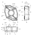
- FIG. 1 It is a whole perspective view which shows the cutting insert for drills concerning one Embodiment of this invention.
- A is a top view which shows the cutting insert for drills shown in FIG. 1,
- (b) is the front view,
- (c) is the side view.
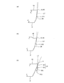
- (A) is an enlarged view showing a cross section taken along line AA in FIG. 2 (a)
- (b) is an enlarged view showing a cross section taken along line BB in FIG. 2 (a)
- (c) ) Is an enlarged view showing a cross section taken along the line CC of FIG. It is a whole perspective view which shows the cutting insert for drills concerning other embodiment of this invention.
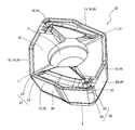
- FIG. 6A is an enlarged side view showing the second insert pocket shown in FIG. 6B
- FIG. 6B is a view showing a state in which the insert is attached to the enlarged view showing a section taken along the line DD of FIG.
- FIG. 6A is an enlarged side view showing the second insert pocket shown in FIG. 6B
- FIG. 6B is a view showing a state in which the insert is attached to the enlarged view showing a section taken along the line DD of FIG.
- (A)-(c) is a schematic explanatory drawing which shows the cutting method of the cut material which concerns on one Embodiment of this invention.
- the insert 1 includes an upper surface 10, a lower surface 2 corresponding to the upper surface 10, and a side surface 20 positioned between the upper surface 10 and the lower surface 2. ing.
- a part of the upper surface 10 functions as a rake surface on which generated chips are scraped.
- the upper surface 10 has a first corner portion 11, and a first side 12 and a second side 13 disposed on both sides of the first corner portion 11.
- the upper surface 10 has a substantially quadrangular shape, specifically a substantially rhombus shape in the top view shown in FIG.
- a through hole 3 is formed at the center of the upper surface 10.
- the through hole 3 is for screwing and penetrates from the upper surface 10 to the lower surface 2.
- the insert 1 has a 180-degree rotationally symmetric shape with the central axis of the through hole 3 as a rotation axis. Therefore, the upper surface 10 has a pair of first corner portions 11, 11, a pair of first sides 12, 12, and a pair of second sides 13, 13 arranged to face each other.
- the pair of first corner portions 11 and 11 are located on one diagonal line of the upper surface 10.
- the upper surface 10 further includes a pair of second corner portions 14 and 14 located on the other diagonal line of the upper surface 10.
- the first corner portion 11 is located at an obtuse angle corner
- the second corner portion 14 is located at an acute angle corner.
- the insert 1 has a first cutting edge 15 formed along the first side 12 and a second cutting edge 16 formed along the second side 13.
- the first cutting edge 15 and the second cutting edge 16 are formed adjacent to each other via the first corner portion 11.
- the side surface 20 includes a first area 25 corresponding to the first cutting edge 15, a second area 26 corresponding to the second cutting edge 16, and a third area 21 corresponding to the first corner portion 11. Yes.
- the first region 25, the second region 26, and the third region 21 each function as a flank.
- the said flank should just be a side surface of the insert which functions as a flank with respect to the cutting blade which respond
- the third region 21 has an upper region 22 provided on the upper surface 10 side in the vicinity of the first corner portion 11, and a lower region 23 located below the upper region 22.
- the upper region 22 is continuous with the first region 25 and the second region 26. That is, the upper region 22 is formed so as to be smoothly connected to the first region 25 and the second region 26.
- the lower region 23 is formed in a planar shape.
- the first region 25 has an inclination angle ⁇ 1 with respect to the lower surface 2 as shown in FIG.
- the second region 26 has an inclination angle ⁇ 2 with respect to the lower surface 2 as shown in FIG.
- the upper region 22 has an inclination angle ⁇ 4 with respect to the lower surface 2 as shown in FIG.
- the inclination angle ⁇ 4 is equal to the inclination angle ⁇ 1 at one end located on the first region 25 side, and is equal to the inclination angle ⁇ 2 at the other end located on the second region 26 side.
- the lower region 23 has an inclination angle ⁇ 3 with respect to the lower surface 2 as shown in FIG. In the present embodiment, the inclination angle ⁇ 3 is larger than the inclination angle ⁇ 1 and the inclination angle ⁇ 2.
- the cutting edge strength in the vicinity of the first corner portion 11 can be ensured by the upper region 22 continuing to the first corner portion 11.
- the restraint side surface of the insert pocket that faces the first corner portion 11 located on the side that does not participate in cutting in the insert 1 is more inward of the holder. It can be formed to be located.
- the insert 1 is attached to the second insert pocket 70 so that a part of the second cutting edge 16 protrudes from the front end side of the holder 51 with the outer periphery side insert 1B.
- the first corner portion 11 a located on the side of the pair of first corner portions 11, 11 that is not involved in cutting is the outer peripheral side of the holder 51 in the second insert pocket 70 and the proximal end of the holder 51. Placed on the side.
- the inclination angle ⁇ 3 in the lower region 23 of the first corner portion 11a is large. Therefore, as shown in FIG. 6B and FIG.
- the strength of the holder part in which the inner peripheral side insert pocket and the outer peripheral side insert pocket are formed is improved even in a small-diameter throw-away drill in which the holder itself is small in strength and the volume of the insert occupying the holder is large. Can do. Therefore, even in a small-diameter throw-away drill, it is possible to suitably reduce the damage of the holder.
- the cutting resistance generated in the cutting blade is increased, the holder is liable to be vibrated and swung, and the holder of the present embodiment is also used in high feed machining in which irregular bending of the holder is likely to occur. According to this, the occurrence of breakage of the holder due to insufficient strength of the holder portion can be suitably reduced.
- the inclination angle can be determined as an angle formed between each region and a line L1 substantially perpendicular to the placement surface when the insert 1 is placed on a flat placement surface. That is, in the cross-section substantially perpendicular to the cutting edge corresponding to each region as shown in FIG. 3, the angle formed by the line L1 substantially perpendicular to the lower surface 2 and each region can be set as the inclination angle.
- the inclination angle ⁇ 2 is larger than the inclination angle ⁇ 1 ( ⁇ 2> ⁇ 1).
- the inclination angle ⁇ 4 increases from the first region 25 side toward the second region 26 side.
- the inclination angle ⁇ 3 is constant in the direction along the first corner portion 11.
- the dimension H1 of the lower region 23 in the height direction is larger than the dimension H2 of the upper region 22 in the height direction (H1> H2).
- the area of the lower region 23 inclined at a large inclination angle corresponding to the area of the restraining side surface of the second insert pocket opposed to the third region 21 is increased. Therefore, the constraining side surface of the second insert pocket can be further arranged on the inner peripheral side of the holder. Therefore, the thickness of the outer wall portion S2 can be further increased.
- the dimensions H1 and H2 in the height direction refer to the maximum value among the dimensions in a direction substantially perpendicular to the lower surface 2 when the insert 1 is placed on a flat mounting surface.
- the dimension W in the width direction of the lower region 23 increases from the upper surface 10 side toward the lower surface 2 side. Thereby, since the area of the lower area
- the dimension W in the width direction means the maximum value among the dimensions in a direction substantially parallel to the lower surface 2 when the insert 1 is placed on a flat mounting surface.
- the above-described insert 1 is configured to exhibit the above effects when used as the outer peripheral side insert 1B.
- the insert according to the present invention is not limited to the shape of the insert 1. That is, in one embodiment of the insert according to the present invention, when attached to the insert pocket, the side surface corresponding to the corner portion located on the outer peripheral side of the holder and on the proximal end side of the holder in the insert pocket is the configuration described above. Make.
- the insert according to another embodiment of the present invention can also be configured to exhibit the above-described effects when it is attached to the holder as either an inner peripheral side insert or an outer peripheral side insert. That is, when the insert according to another embodiment of the present invention is attached to the first insert pocket 60 and the second insert pocket 70 as the inner peripheral side insert 1A and the outer peripheral side insert 1B, as shown in FIG.
- the side surface corresponding to the corner part located in the outer peripheral side of the holder 51 in the corresponding insert pocket and on the base end side of the holder 51 and located on the side not involved in cutting can also be configured to form the above-described configuration.
- the same components as those in FIGS. 1 to 3 described above are denoted by the same reference numerals and description thereof is omitted.
- the first cutting edge 15 is formed adjacent to the two second cutting edges 16 and 16, and one end is connected to the first corner portion 11. The other end is connected to the second corner portion 31.
- the second cutting edge 16 has one end connected to the first corner portion 11 and the other end connected to the second corner portion 31.
- the side surface 20 further includes a fourth region 32 corresponding to the second corner portion 31.
- the fourth region 32 includes an upper region 33 provided on the upper surface 10 side in the vicinity of the second corner portion 31, and a lower region 34 positioned below the upper region 33.
- An inclination angle ⁇ 5 (not shown) with respect to the lower surface 2 of the lower region 34 is larger than the inclination angle ⁇ 1 and the inclination angle ⁇ 2. That is, in the insert 30, the inclination angle ⁇ 3 and the inclination angle ⁇ 5 are both larger than the inclination angle ⁇ 1 and the inclination angle ⁇ 2.
- the insert 30 when the insert 30 is used for either the inner peripheral side insert 1A or the outer peripheral side insert 1B, the outer wall portion of the holder located on the outer peripheral side of the holder 51 in the corresponding insert pocket as shown in FIG. A large thickness of S1 and S2 can be secured. Therefore, according to the insert 30, the strength of the portion of the holder 51 where the first and second insert pockets 60 and 70 are formed can be increased, and the effect of reducing breakage of the holder 51 is enhanced.
- the outer wall S ⁇ b> 1 of the holder 51 located on the outer peripheral side of the holder 51 in the first insert pocket 60 is cut.
- the proximal end side of the holder 51 that faces the corner portion that is located on the side not involved in the process it must be particularly small.
- the insert 30 as described above, it is possible to ensure a large thickness on the base end side of the outer wall portion S1. Therefore, even if the insert has an approximately rhombus shape when viewed from the top, the strength on the proximal end side of the outer wall portion S1 can be increased, and damage to the holder during processing can be reduced.
- Other configurations are the same as those of the insert 1 according to the above-described embodiment.
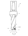
- a drill according to an embodiment of the present invention will be described in detail with reference to FIGS. 5 to 7 by taking as an example the case where the insert 1 is mounted.
- the drill 50 according to this embodiment has two inserts 1 attached to the tip of a holder 51.
- the drill 50 includes an inner peripheral side insert 1A mounted on the inner peripheral side of the tip of the holder 51 and an outer peripheral side insert 1B mounted on the outer peripheral side.
- a first insert pocket 60 (inner peripheral side insert pocket) and a second insert pocket 70 (outer peripheral side insert pocket) are formed at the tip of the holder 51, respectively.
- the 1st insert pocket 60 is formed in the inner peripheral side of the front-end
- the second insert pocket 70 is the tip of the holder 51 and is formed on the outer peripheral side of the holder 51 with respect to the first insert pocket 60.
- the inner peripheral side insert 1 ⁇ / b> A is attached to the first insert pocket 60 with at least a part of the first cutting edge 15 protruding from the tip of the holder 51. At this time, the inner peripheral side insert 1 ⁇ / b> A is attached so that the first corner portion 11 is positioned on the outer peripheral side of the holder 51 on the distal end side of the holder 51.
- the outer peripheral side insert 1 ⁇ / b> B is attached to the second insert pocket 70 with at least a part of the second cutting edge 16 protruding from the tip of the holder 51.
- the outer periphery side insert 1 ⁇ / b> B is attached on the tip end side of the holder 51 so that the first corner portion 11 is positioned on the inner periphery side of the holder 51 and the second corner portion 14 is positioned on the outer periphery side of the holder 51.
- the first cutting edge 15 of the inner peripheral side insert 1A functions as an inner peripheral cutting edge that cuts the inner peripheral side of the hole bottom surface
- the second cutting edge 16 of the outer peripheral side insert 1B is the hole bottom surface. It functions as an outer peripheral cutting edge that cuts the outer peripheral side.
- the 1st corner part 11a located in the side which does not participate in cutting among a pair of 1st corner parts 11 and 11 of outer peripheral side insert 1B is the outer peripheral side of the holder 51 in the 2nd insert pocket 70, and the base of the holder 51 is. It is arranged on the end side.
- the inclination angle ⁇ 3 in the lower region 23 of the first corner portion 11a is larger than the inclination angle ⁇ 1 and the inclination angle ⁇ 2. Therefore, as shown in FIG. 6B, it is possible to ensure a large thickness of the outer wall portion S ⁇ b> 2 of the holder 51 located on the outer peripheral side of the holder 51 in the second insert pocket 70 and on the proximal end side of the holder 51. Thereby, the holder 51 with high strength of the outer wall portion S2 can be realized, and the life of the holder can be improved. As a result, the drill 50 can reduce breakage of the holder caused by insufficient strength of the outer wall during processing as in the prior art, and can exhibit excellent cutting performance over a long period of time.
- the first insert pocket 60 and the second insert pocket 70 are respectively restrained seat surfaces 61, 71, first restraint side surfaces 62, 72, second restraint side surfaces 63, 73, 3rd restraint side surfaces 64 and 74 are provided.
- the first constraining side surfaces 62 and 72 are located on the inner peripheral side of the holder 51
- the second constraining side surfaces 63 and 73 are located on the outer peripheral side of the holder 51.
- the third constraining side surfaces 64 and 74 are located on the proximal end side of the holder 51 between the first constraining side surfaces 62 and 72 and the second constraining side surfaces 63 and 73.
- the restraining seat surfaces 61 and 71 are in contact with the lower surface 2 of the insert 1.
- the first and third restraining side surfaces 62, 64, 72, 74 abut on the side surface 20 of the insert 1.
- the arrangement of the first restraining side surfaces 62 and 72 and the second restraining side surfaces 63 and 73 of the first insert pocket 60 and the second insert pocket 70 corresponds to the shapes of the inner peripheral side insert 1A and the outer peripheral side insert 1B to be attached. Each is different. Specifically, as shown in FIG. 6A, the first constraining side surface 62 and the second constraining side surface 63 of the first insert pocket 60 form the outer wall portion S1 as it goes from the proximal end of the holder 51 to the distal end. The holder 51 is inclined so as to move away from the outer peripheral surface of the holder 51.
- the second insert pocket 70 opens in the first restraint side surface 72 and the second restraint side surface 73 of the second insert pocket 70 from the distal end of the holder 51 toward the base end.
- the holder 51 is provided so as to be inclined away from the outer peripheral surface.
- the second insert pocket 70 is formed so that the lower portion 76 of the second restraint side surface 73 protrudes inward of the holder 51. More specifically, the upper portion 75 of the second restraint side surface 73 is formed so as to be inclined away from the outer peripheral surface of the holder 51 toward the restraint seat surface 71, and the lower portion 76 has a step from the upper portion 75. It is formed to protrude inward of the holder 51 so as to form.
- FIG. 7B is a cross-sectional view perpendicular to the restraining seat surface 71 of the second insert pocket 70.
- outer peripheral side insert 1B is arranged in the second insert pocket 70 so that the lower region 76 faces the third region 21 corresponding to the first corner portion 11a located on the side not involved in cutting, more specifically, the lower region 23. Attached to. Thereby, the intensity
- the lower portion 76 is formed to have a stepped portion having an upper surface 76a that is substantially parallel to the restraining seat surface 71.
- the configuration of the lower portion is not limited to this, and the inner portion of the holder 51 is not limited thereto. As long as it is formed so as to protrude, it may be formed in a planar shape.
- the second insert pocket 70 has an inclination angle ⁇ 6 with respect to the restraining seat surface 71 of the second restraining side surface 73 facing the second restraining side surface 73 and on the side not involved in cutting. It is smaller than the inclination angle ⁇ 3 corresponding to the first corner portion 11a located ( ⁇ 6 ⁇ 3).
- the thickness of the outer wall portion S2 can be increased to ensure the strength of the holder 51, and the lower region 23 of the outer peripheral side insert 1B can be reduced from interfering with the second restraining side surface 73.
- the life of the entire drill can be improved, and stable cutting can be performed over a long period of time.
- the inclination angle ⁇ 6 can be obtained as an angle formed by a line L2 substantially perpendicular to the restraining seat surface 71 and the second restraining side surface 73 in a cross section substantially perpendicular to the restraining seat surface 71.
- the drill and holder of this invention are not limited to this embodiment.
- the first insert pocket 60 may be a drill including a holder having the above configuration.
- the first insert pocket 60 may be a holder having the above configuration.
- the work material cutting method according to the present embodiment includes the following steps (i) to (iv).
- the cutting is performed using the drill 50 having a long tool life that can reduce the breakage of the holder 51 during cutting, it is possible to stably realize cutting with excellent processing accuracy over a long period of time. is there.
- any one of the drill 50 and the work material 100 may be rotated.
- the cutting edges 15 and 16 and the work material 100 may be relatively close to each other.
- the work material 100 may be close to the cutting edges 15 and 16.
- the work material 100 and the cutting edges 15 and 16 need only be relatively distant from each other.
- the work material 100 may be moved away from the cutting edges 15 and 16. Good.
- the cutting blades 15 and 16 of the drill 50 are brought into contact with different portions of the work material 100 while maintaining the state where either the drill 50 or the work material 100 is rotated. What is necessary is just to repeat a process.
- the insert 1 may be rotated 180 degrees with respect to the central axis of the through hole 3 and an unused cutting blade may be used.
- the present invention is not limited to the above embodiment, and it goes without saying that the present invention can be arbitrarily set without departing from the object of the present invention.
- the side surface corresponding to the corner portion located on the outer periphery side of the holder in the first insert pocket and on the proximal end side of the holder and positioned on the side not involved in cutting may be used.
- the lower region 23 is formed in a planar shape.
- the lower region may be formed in a curved surface shape.
Abstract
Description
前記ドリルおよび被削材のいずれか一方を回転させる工程。
前記ドリルの前記第1切刃および前記第2切刃を前記被削材に近接させる工程。
前記ドリルの前記第1切刃および前記第2切刃を前記被削材の表面に接触させ、前記被削材を切削する工程。
前記被削材から前記第1切刃および前記第2切刃を離間させる工程。 The cutting method of the workpiece which concerns on the form of this invention has the following processes.
A step of rotating either the drill or the work material;
The step of bringing the first cutting edge and the second cutting edge of the drill close to the work material.
The step of bringing the first cutting edge and the second cutting edge of the drill into contact with the surface of the work material and cutting the work material.
Separating the first cutting edge and the second cutting edge from the work material.
前記被削材の切削方法によれば、加工精度の優れた切削加工を安定して長期に渡って実現することができる。 According to the drill cutting insert and the drill, while maintaining the strength of the corner portion of the insert, the thickness of the outer wall portion of the holder facing the corner portion located on the side not involved in cutting, that is, the insert to which the insert is attached The thickness of the holder portion located on the outer peripheral side of the holder in the pocket and on the proximal end side of the holder can be increased. As a result, the strength of the portion of the holder is increased, and the tool life can be improved.
According to the cutting method of the work material, it is possible to stably realize cutting with excellent processing accuracy over a long period of time.
以下、本発明の一実施形態に係るインサートについて、図1~図3を参照して詳細に説明する。図1および図2に示すように、本実施形態に係るインサート1は、上面10と、該上面10に対応する下面2と、上面10と下面2との間に位置する側面20と、を備えている。 <Cutting insert for drill>
Hereinafter, an insert according to an embodiment of the present invention will be described in detail with reference to FIGS. As shown in FIGS. 1 and 2, the
次に、本発明の一実施形態に係るドリルについて、前記したインサート1を装着した場合を例に挙げ、図5~図7を参照して詳細に説明する。本実施形態に係るドリル50は、図5に示すように、ホルダ51の先端部にインサート1を2つ装着してなる。 <Drill>
Next, a drill according to an embodiment of the present invention will be described in detail with reference to FIGS. 5 to 7 by taking as an example the case where the
なお、図7(b)は、第2インサートポケッ70の拘束座面71に垂直な断面図である。 Thereby, the intensity | strength of the part (lower part 76) located in the
FIG. 7B is a cross-sectional view perpendicular to the restraining
次に、本発明の被削材の切削方法に係る一実施形態について、前記したドリル50を用いた場合を例に挙げ、図8を参照して詳細に説明する。本実施形態に係る被削材の切削方法は、以下の(i)~(iv)の工程を有する。 <Cutting method of work material>
Next, an embodiment according to the method for cutting a work material of the present invention will be described in detail with reference to FIG. 8 by taking the case of using the
(ii)図8(a)に示すように、ドリル50を、矢印bに示す方向に動かし、ドリル50の第1切刃15,第2切刃16を被削材100に近接させる工程。
(iii)図8(b)に示すように、ドリル50を、更に矢印bに示す方向に動かし、ドリル50の第1切刃15,第2切刃16を被削材100の表面に接触させ、被削材100を切削(穴あけ加工)する工程。
(iv)図8(c)に示すように、ドリル50を、矢印cに示す方向に動かし、被削材100から第1切刃15,第2切刃16を離間させる工程。 (I) A step of rotating the
(Ii) A step of moving the
(Iii) As shown in FIG. 8B, the
(Iv) A step of moving the
Claims (15)
- 第1コーナー部と該第1コーナー部の両側に配置された第1辺と第2辺とを有する上面と、該上面に対応する下面と、前記上面と前記下面との間に位置する側面と、を備えたドリル用切削インサートであって、
前記第1辺に沿って形成された第1切刃と、
前記第2辺に沿って形成された第2切刃と、を有し、
前記側面は、前記第1切刃に対応する第1領域と、前記第2切刃に対応する第2領域と、前記第1コーナー部に対応する第3領域と、を有しており、
前記第3領域は、前記第1コーナー部に近接して前記上面側に設けられた上領域と、該上領域の下方に位置する下領域と、を有し、
前記下領域の前記下面に対する傾斜角度θ3は、前記第1領域の前記下面に対する傾斜角度θ1および前記第2領域の前記下面に対する傾斜角度θ2よりも大きいドリル用切削インサート。 An upper surface having a first corner portion and first and second sides disposed on both sides of the first corner portion; a lower surface corresponding to the upper surface; and a side surface located between the upper surface and the lower surface. A cutting insert for a drill comprising:
A first cutting edge formed along the first side;
A second cutting edge formed along the second side,
The side surface includes a first region corresponding to the first cutting edge, a second region corresponding to the second cutting edge, and a third region corresponding to the first corner portion,
The third region has an upper region provided on the upper surface side in the vicinity of the first corner portion, and a lower region located below the upper region,
The drill cutting insert having an inclination angle θ3 of the lower region with respect to the lower surface larger than an inclination angle θ1 of the first region with respect to the lower surface and an inclination angle θ2 of the second region with respect to the lower surface. - 前記傾斜角度θ2は、前記傾斜角度θ1よりも大きく、
前記上領域の前記下面に対する傾斜角度θ4は、前記第1領域側から前記第2領域側に向かうにつれて増加し、
前記傾斜角度θ3は、前記第1コーナー部に沿う方向において、一定である請求項1に記載のドリル用切削インサート。 The inclination angle θ2 is larger than the inclination angle θ1,
The inclination angle θ4 of the upper region with respect to the lower surface increases from the first region side toward the second region side,
The drill cutting insert according to claim 1, wherein the inclination angle θ <b> 3 is constant in a direction along the first corner portion. - 側面視において、前記下領域の高さ方向における寸法は、前記上領域の高さ方向における寸法よりも大きい請求項1に記載のドリル用切削インサート。 2. The drill cutting insert according to claim 1, wherein, in a side view, the dimension in the height direction of the lower region is larger than the dimension in the height direction of the upper region.
- 側面視において、前記下領域の幅方向における寸法は、前記上面側から前記下面側に向かうにつれて増大している請求項3に記載のドリル用切削インサート。 4. The drill cutting insert according to claim 3, wherein, in a side view, a dimension in the width direction of the lower region increases from the upper surface side toward the lower surface side.
- 前記上面は、上面視において略四角形形状をなすとともに、互いに対向配置された一対の前記第1コーナー部と、一対の前記第1辺と、一対の前記第2辺とを有し、
前記一対の第1コーナー部は、前記上面の一方の対角線上に位置しており、
前記上面は、該上面の他方の対角線上に位置する一対の第2コーナー部をさらに有している請求項1に記載のドリル用切削インサート。 The upper surface has a substantially quadrangular shape in a top view, and has a pair of the first corner portions arranged to face each other, a pair of the first sides, and a pair of the second sides,
The pair of first corner portions are located on one diagonal line of the upper surface,
The drill cutting insert according to claim 1, wherein the upper surface further includes a pair of second corner portions positioned on the other diagonal line of the upper surface. - 前記側面は、前記第2コーナー部に対応する第4領域をさらに有しており、
前記第4領域は、前記第2コーナー部に近接して前記上面側に設けられた上領域と、該上領域の下方に位置する下領域と、を有し、
前記第4領域における前記下領域の前記下面に対する傾斜角度θ5は、前記傾斜角度θ1および前記傾斜角度θ2よりも大きい請求項5に記載のドリル用切削インサート。 The side surface further includes a fourth region corresponding to the second corner portion,
The fourth region has an upper region provided on the upper surface side in the vicinity of the second corner portion, and a lower region located below the upper region,
The drill cutting insert according to claim 5, wherein an inclination angle θ5 of the lower region in the fourth region with respect to the lower surface is larger than the inclination angle θ1 and the inclination angle θ2. - 上面視において略四角形形状をなし、一方の対角線上に位置する一対の第1コーナー部と、各第1コーナー部の両側に配置された第1辺と第2辺と、互いに異なる前記第1コーナー部に対応して配置された前記第1辺および前記第2辺間に配置され且つ他方の対角線上に位置する一対の第2コーナー部とを有する上面と、
該上面に対応する下面と、
前記上面と前記下面との間に位置する側面と、を備えたドリル用切削インサートであって、
前記第1辺に沿って形成された第1切刃と、
前記第2辺に沿って形成された第2切刃と、を有し、
前記側面は、前記第1切刃に対応する第1領域と、前記第2切刃に対応する第2領域と、前記第1コーナー部に対応する第3領域と、前記第2コーナー部に対応する第4領域と、を有しており、
前記第3領域および前記第4領域は、各々、前記第1コーナー部および前記第2コーナー部に近接して前記上面側に設けられた上領域と、該上領域の下方に位置する下領域と、を有し、
前記第3領域における前記下領域の前記下面に対する傾斜角度θ3および前記第4領域における前記下領域の前記下面に対する傾斜角度θ5は、いずれも前記第1領域の前記下面に対する傾斜角度θ1および前記第2領域の前記下面に対する傾斜角度θ2よりも大きいドリル用切削インサート。 The first corners having a substantially quadrangular shape when viewed from above and having a pair of first corner portions located on one diagonal line, and first and second sides disposed on both sides of each first corner portion, are different from each other. An upper surface having a pair of second corner portions disposed between the first side and the second side and disposed on the other diagonal line corresponding to the portion;
A lower surface corresponding to the upper surface;
A cutting insert for drill comprising a side surface located between the upper surface and the lower surface,
A first cutting edge formed along the first side;
A second cutting edge formed along the second side,
The side surface corresponds to a first region corresponding to the first cutting edge, a second region corresponding to the second cutting edge, a third region corresponding to the first corner portion, and the second corner portion. A fourth region to be
The third region and the fourth region are respectively an upper region provided on the upper surface side in the vicinity of the first corner portion and the second corner portion, and a lower region located below the upper region. Have
In the third region, an inclination angle θ3 with respect to the lower surface of the lower region and an inclination angle θ5 with respect to the lower surface of the lower region in the fourth region are both an inclination angle θ1 with respect to the lower surface of the first region and the second A cutting insert for drill that is larger than an inclination angle θ2 with respect to the lower surface of the region. - 先端部に形成された第1インサートポケットと、該第1インサートポケットよりも外周側の先端部に形成された第2インサートポケットと、を備えたホルダと、
前記第1コーナー部を少なくとも2つ有する請求項1~7のいずれかに記載の一対のドリル用切削インサートと、を備えたドリルであって、
前記一対のドリル用切削インサートのうち一方が、前記第1切刃の少なくとも一部を前記ホルダの先端から突出させるよう前記第1インサートポケットに取り付けられ、
他方が、前記第2切刃の少なくとも一部を前記ホルダの先端から突出させるよう前記第2インサートポケットに取り付けられるとともに、
前記一対のドリル用切削インサートのうち少なくとも一方は、前記ドリル用切削インサートにおいて前記2つの第1コーナー部のうち切削に関与しない側に位置する第1コーナー部が、当該ドリル用切削インサートを取り付けたインサートポケットにおけるホルダの外周側で且つホルダの基端側に配置されるよう、前記インサートポケットに取り付けられているドリル。 A holder provided with a first insert pocket formed at the tip portion, and a second insert pocket formed at the tip portion on the outer peripheral side of the first insert pocket;
A pair of drill cutting inserts according to any one of claims 1 to 7 having at least two first corner portions,
One of the pair of drill cutting inserts is attached to the first insert pocket so that at least a part of the first cutting blade protrudes from the tip of the holder,
The other is attached to the second insert pocket so that at least a part of the second cutting edge protrudes from the tip of the holder,
At least one of the pair of drill cutting inserts has a first corner portion positioned on a side not involved in cutting of the two first corner portions in the drill cutting insert. The drill attached to the said insert pocket so that it may be arrange | positioned in the outer peripheral side of the holder in an insert pocket, and the base end side of a holder. - 前記第1インサートポケットおよび前記第2インサートポケットは、各々、前記ドリル用切削インサートの前記下面に当接する拘束座面と、前記ホルダの外周側に位置し且つ前記ドリル用切削インサートの前記側面に対応する拘束側面と、を備えており、
前記第1インサートポケットおよび前記第2インサートポケットのうち少なくとも一方は、前記拘束側面の下部が、前記ホルダの内方に突出するよう形成されている請求項8に記載のドリル。 The first insert pocket and the second insert pocket respectively correspond to a restraint seat surface that contacts the lower surface of the drill cutting insert, and an outer peripheral side of the holder and corresponds to the side surface of the drill cutting insert. A restraining side surface,
The drill according to claim 8, wherein at least one of the first insert pocket and the second insert pocket is formed such that a lower portion of the restraining side surface protrudes inward of the holder. - 前記拘束側面の下部に、前記切削に関与しない側に位置する第1コーナー部に対応する前記第3領域が対向するよう、前記ドリル用切削インサートが前記インサートポケットに取り付けられている請求項9に記載のドリル。 The drill cutting insert is attached to the insert pocket so that the third region corresponding to the first corner portion located on the side not involved in the cutting is opposed to the lower portion of the constraining side surface. The drill described.
- 前記第1インサートポケットおよび前記第2インサートポケットのうち少なくとも一方は、前記拘束側面の前記拘束座面に対する傾斜角度θ6が、前記拘束側面と対向するとともに前記切削に関与しない側に位置するコーナー部に対応する前記傾斜角度θ3よりも小さい請求項8~10のいずれかに記載のドリル。 At least one of the first insert pocket and the second insert pocket is provided at a corner portion where the inclined side surface θ of the constraining side surface with respect to the constraining seat surface is opposite to the constraining side surface and located on the side not involved in the cutting. The drill according to any one of claims 8 to 10, which is smaller than the corresponding inclination angle θ3.
- 先端部に形成された第1インサートポケットと、該第1インサートポケットよりも外周側の先端部に形成された第2インサートポケットと、を備えたホルダと、
一対のドリル用切削インサートと、を備えたドリルであって、
前記一対のドリル用切削インサートは、各々、少なくとも2つのコーナー部と各コーナー部の両側に配置された第1辺と第2辺とを有する上面と、該上面に対応する下面と、前記上面と前記下面との間に位置する側面と、前記第1辺に沿って形成された第1切刃と、前記第2辺に沿って形成された第2切刃と、を備え、
前記側面は、前記第1切刃に対応する第1領域と、前記第2切刃に対応する第2領域と、前記コーナー部に対応する第3領域と、を有しており、
前記第3領域は、前記コーナー部に近接して前記上面側に設けられた上領域と、該上領域の下方に位置する下領域と、を有し、
前記下領域の前記下面に対する傾斜角度θ3は、前記第1領域の前記下面に対する傾斜角度θ1および前記第2領域の前記下面に対する傾斜角度θ2よりも大きく、
前記一対のドリル用切削インサートのうち一方が、前記第1切刃の少なくとも一部を前記ホルダの先端から突出させるよう前記第1インサートポケットに取り付けられ、
他方が、前記第2切刃の少なくとも一部を前記ホルダの先端から突出させるよう前記第2インサートポケットに取り付けられるとともに、
前記一対のドリル用切削インサートのうち少なくとも一方は、前記ドリル用切削インサートにおいて前記2つのコーナー部のうち切削に関与しない側に位置するコーナー部が、当該ドリル用切削インサートを取り付けたインサートポケットにおけるホルダの外周側で且つホルダの基端側に配置されるよう、前記インサートポケットに取り付けられているドリル。 A holder provided with a first insert pocket formed at the tip portion, and a second insert pocket formed at the tip portion on the outer peripheral side of the first insert pocket;
A drill comprising a pair of drill cutting inserts,
Each of the pair of drill cutting inserts includes at least two corner portions, an upper surface having first and second sides disposed on both sides of each corner portion, a lower surface corresponding to the upper surface, and the upper surface, A side surface located between the lower surface, a first cutting edge formed along the first side, and a second cutting edge formed along the second side,
The side surface has a first area corresponding to the first cutting edge, a second area corresponding to the second cutting edge, and a third area corresponding to the corner portion,
The third region has an upper region provided on the upper surface side in the vicinity of the corner portion, and a lower region located below the upper region,
An inclination angle θ3 with respect to the lower surface of the lower region is larger than an inclination angle θ1 with respect to the lower surface of the first region and an inclination angle θ2 with respect to the lower surface of the second region,
One of the pair of drill cutting inserts is attached to the first insert pocket so that at least a part of the first cutting blade protrudes from the tip of the holder,
The other is attached to the second insert pocket so that at least a part of the second cutting edge protrudes from the tip of the holder,
At least one of the pair of drill cutting inserts is a holder in an insert pocket in which a corner portion located on a side not involved in cutting of the two corner portions in the drill cutting insert is mounted with the drill cutting insert. A drill attached to the insert pocket so as to be arranged on the outer peripheral side of the holder and on the proximal end side of the holder. - 先端部に形成された第1インサートポケットと、該第1インサートポケットよりも外周側の先端部に形成された第2インサートポケットと、を備えたホルダであって、
前記第1インサートポケットおよび前記第2インサートポケットは、各々、ドリル用切削インサートの下面に当接する拘束座面と、前記ホルダの外周側に位置し且つ前記ドリル用切削インサートの側面に対応する拘束側面と、を備えており、
前記第1インサートポケットおよび前記第2インサートポケットのうち少なくとも一方は、前記拘束側面の下部が、前記ホルダの内方に突出するよう形成されているホルダ。 A holder comprising a first insert pocket formed at a tip portion, and a second insert pocket formed at a tip portion on the outer peripheral side of the first insert pocket,
The first insert pocket and the second insert pocket are each a restraint seat surface that contacts the lower surface of the drill cutting insert, and a restraint side surface that is located on the outer peripheral side of the holder and corresponds to the side surface of the drill cutting insert And,
At least one of the first insert pocket and the second insert pocket is a holder formed such that a lower portion of the restraining side surface protrudes inward of the holder. - 前記拘束側面の上部が、前記拘束座面に向かうにつれて、前記ホルダの外周面から遠ざかるよう傾斜して形成されているとともに、
前記拘束側面の下部が、前記上部から段差を形成するよう前記ホルダの内方に突出して形成されている請求項13に記載のホルダ。 The upper portion of the restraint side surface is formed so as to be inclined away from the outer peripheral surface of the holder as it goes toward the restraint seat surface,
The holder according to claim 13, wherein a lower portion of the constraining side surface is formed to protrude inward of the holder so as to form a step from the upper portion. - 請求項8~12のいずれかに記載のドリルおよび被削材のいずれか一方を回転させる工程と、
前記ドリルの前記第1切刃および前記第2切刃を前記被削材に近接させる工程と、
前記ドリルの前記第1切刃および前記第2切刃を前記被削材の表面に接触させ、前記被削材を切削する工程と、
前記被削材から前記第1切刃および前記第2切刃を離間させる工程と、を有した被削材の切削方法。 Rotating one of the drill and the work material according to any one of claims 8 to 12,
Bringing the first cutting edge and the second cutting edge of the drill close to the work material;
Contacting the first cutting edge and the second cutting edge of the drill with the surface of the work material, and cutting the work material;
And a step of separating the first cutting edge and the second cutting edge from the work material.
Priority Applications (4)
| Application Number | Priority Date | Filing Date | Title |
|---|---|---|---|
| CN200980106298.1A CN101959633B (en) | 2008-02-27 | 2009-02-27 | Cutting insert for drill, drill, and cutting method using same |
| EP09714448.9A EP2260960B1 (en) | 2008-02-27 | 2009-02-27 | Cutting insert for drill, drill, and cutting method using same |
| US12/918,463 US8911183B2 (en) | 2008-02-27 | 2009-02-27 | Cutting insert for drill, drill, and method of cutting using the same |
| JP2010500776A JP5060614B2 (en) | 2008-02-27 | 2009-02-27 | Cutting insert for drill, drill, and cutting method using the same |
Applications Claiming Priority (2)
| Application Number | Priority Date | Filing Date | Title |
|---|---|---|---|
| JP2008-045524 | 2008-02-27 | ||
| JP2008045524 | 2008-02-27 |
Publications (1)
| Publication Number | Publication Date |
|---|---|
| WO2009107789A1 true WO2009107789A1 (en) | 2009-09-03 |
Family
ID=41016174
Family Applications (1)
| Application Number | Title | Priority Date | Filing Date |
|---|---|---|---|
| PCT/JP2009/053709 WO2009107789A1 (en) | 2008-02-27 | 2009-02-27 | Cutting insert for drill, drill, and cutting method using same |
Country Status (5)
| Country | Link |
|---|---|
| US (1) | US8911183B2 (en) |
| EP (1) | EP2260960B1 (en) |
| JP (1) | JP5060614B2 (en) |
| CN (1) | CN101959633B (en) |
| WO (1) | WO2009107789A1 (en) |
Families Citing this family (16)
| Publication number | Priority date | Publication date | Assignee | Title |
|---|---|---|---|---|
| US8337123B2 (en) * | 2007-05-28 | 2012-12-25 | Kyocera Corporation | Cutting insert, cutting tool, and cutting method using the cutting tool |
| US9403215B2 (en) * | 2011-04-11 | 2016-08-02 | Sumitomo Electric Industries, Ltd. | Cutting tool and method for producing same |
| KR101222291B1 (en) | 2011-07-20 | 2013-01-15 | 대구텍 유한회사 | Drill tool |
| DE102012014092B4 (en) | 2011-07-22 | 2020-12-17 | Kennametal India Ltd. | Indexable drill bit and drill body with indexable drill bit |
| DE102012012980B4 (en) | 2011-07-22 | 2019-10-17 | Kennametal India Ltd. | drilling |
| EP2734328B1 (en) | 2011-07-22 | 2018-03-07 | Kennametal India Limited | An indexable drill insert |
| US8647026B2 (en) | 2011-11-23 | 2014-02-11 | Kennametal Inc. | Cutting tool with pocket feature for reducing stress |
| US8621964B2 (en) | 2011-11-23 | 2014-01-07 | Kennametal Inc. | Rotary cutting tool with coolant passage disposed in non-circular recess for reducing stress |
| CN103447591B (en) | 2012-05-28 | 2020-02-28 | 钴碳化钨硬质合金印度有限公司 | Quadrangular indexable drill insert |
| WO2014116571A1 (en) | 2013-01-23 | 2014-07-31 | Kennametal India Limited | Indexable drill insert and rotary cutting tool employing same |
| DE102015224276A1 (en) * | 2014-12-05 | 2016-06-09 | Ceramtec Gmbh | Cutting tip geometry for cutting force reduction during grooving and pulling cut |
| US10556278B2 (en) | 2016-08-16 | 2020-02-11 | Kennametal Inc. | Tool body for a shell end mill and cutting tool |
| KR102386942B1 (en) * | 2017-08-23 | 2022-04-14 | 대구텍 유한책임회사 | Cutting insert for drilling |
| CN112077369A (en) | 2019-06-13 | 2020-12-15 | 肯纳金属印度有限公司 | Indexable drill insert |
| CN112077370A (en) | 2019-06-13 | 2020-12-15 | 肯纳金属印度有限公司 | Indexable drill insert |
| CN112388033A (en) | 2019-08-14 | 2021-02-23 | 肯纳金属印度有限公司 | Indexable drill insert |
Citations (5)
| Publication number | Priority date | Publication date | Assignee | Title |
|---|---|---|---|---|
| JPS58181506A (en) * | 1982-02-26 | 1983-10-24 | カーボロイ インコーポレーテッド | Drill and its throwaway inserted tooth |
| JPH07251302A (en) * | 1994-03-14 | 1995-10-03 | Ngk Spark Plug Co Ltd | Holder for cutting tool |
| JPH07328815A (en) * | 1994-06-06 | 1995-12-19 | Mitsubishi Materials Corp | Throw away chip |
| JPH1029108A (en) | 1996-07-11 | 1998-02-03 | Toshiba Tungaloy Co Ltd | Throwaway type drill and drill tip |
| JP2003094222A (en) * | 2001-09-26 | 2003-04-03 | Kyocera Corp | Throw-away tip for drill |
Family Cites Families (17)
| Publication number | Priority date | Publication date | Assignee | Title |
|---|---|---|---|---|
| DE3842209A1 (en) | 1988-12-15 | 1990-06-21 | Walter Gmbh Montanwerke | DRILLING TOOL FOR METAL MATERIALS, PLASTICS AND THE LIKE |
| IL105758A (en) * | 1993-05-20 | 1996-01-31 | Iscar Ltd | Indexable-insert drill |
| DE4411475A1 (en) * | 1994-04-01 | 1995-10-05 | Walter Ag | Cutting insert, in particular indexable insert |
| IL113122A0 (en) * | 1995-03-24 | 1995-06-29 | Iscar Ltd | A cutting insert |
| JP3329159B2 (en) | 1995-10-25 | 2002-09-30 | 三菱マテリアル株式会社 | Indexable inserts and indexable milling tools |
| SE511224C2 (en) * | 1997-04-30 | 1999-08-30 | Seco Tools Ab | drilling Tools |
| SE519133C2 (en) * | 1998-10-13 | 2003-01-21 | Sandvik Ab | Drill bits for metal drilling |
| US6939090B1 (en) * | 1999-08-17 | 2005-09-06 | Mitsubishi Materials Corporation | Throwaway tip and throwaway-type cutting tool |
| US7220083B2 (en) * | 2003-10-15 | 2007-05-22 | Tdy Industries, Inc. | Cutting insert for high feed face milling |
| SE529979C2 (en) * | 2006-01-30 | 2008-01-22 | Sandvik Intellectual Property | Drill bit and drill bit where the orifice surface of the insert hole has a cross-sectional convex shape |
| JP4976181B2 (en) * | 2006-12-25 | 2012-07-18 | 住友電工ハードメタル株式会社 | Tip placement method for throw-away drills |
| US7905687B2 (en) * | 2007-01-16 | 2011-03-15 | Tdy Industries, Inc. | Cutting insert, tool holder, and related method |
| SE530823C2 (en) | 2007-01-29 | 2008-09-16 | Sandvik Intellectual Property | Lathe cutter and center cutter for this |
| US8480337B2 (en) * | 2007-06-14 | 2013-07-09 | Taegutec, Ltd. | Drill with cutting inserts |
| US7591614B2 (en) * | 2007-11-20 | 2009-09-22 | Kennametal Inc. | Cutting insert with serrations |
| US8062014B2 (en) * | 2007-11-27 | 2011-11-22 | Kennametal Inc. | Method and apparatus using a split case die to press a part and the part produced therefrom |
| US8840346B2 (en) * | 2008-05-23 | 2014-09-23 | Kyocera Corporation | Drill, cutting insert, and method of manufacturing cut product |
-
2009
- 2009-02-27 WO PCT/JP2009/053709 patent/WO2009107789A1/en active Application Filing
- 2009-02-27 CN CN200980106298.1A patent/CN101959633B/en active Active
- 2009-02-27 JP JP2010500776A patent/JP5060614B2/en active Active
- 2009-02-27 US US12/918,463 patent/US8911183B2/en active Active
- 2009-02-27 EP EP09714448.9A patent/EP2260960B1/en active Active
Patent Citations (5)
| Publication number | Priority date | Publication date | Assignee | Title |
|---|---|---|---|---|
| JPS58181506A (en) * | 1982-02-26 | 1983-10-24 | カーボロイ インコーポレーテッド | Drill and its throwaway inserted tooth |
| JPH07251302A (en) * | 1994-03-14 | 1995-10-03 | Ngk Spark Plug Co Ltd | Holder for cutting tool |
| JPH07328815A (en) * | 1994-06-06 | 1995-12-19 | Mitsubishi Materials Corp | Throw away chip |
| JPH1029108A (en) | 1996-07-11 | 1998-02-03 | Toshiba Tungaloy Co Ltd | Throwaway type drill and drill tip |
| JP2003094222A (en) * | 2001-09-26 | 2003-04-03 | Kyocera Corp | Throw-away tip for drill |
Non-Patent Citations (1)
| Title |
|---|
| See also references of EP2260960A4 |
Also Published As
| Publication number | Publication date |
|---|---|
| US8911183B2 (en) | 2014-12-16 |
| CN101959633B (en) | 2014-04-16 |
| CN101959633A (en) | 2011-01-26 |
| US20100329804A1 (en) | 2010-12-30 |
| JP5060614B2 (en) | 2012-10-31 |
| EP2260960B1 (en) | 2014-12-17 |
| EP2260960A4 (en) | 2011-02-16 |
| JPWO2009107789A1 (en) | 2011-07-07 |
| EP2260960A1 (en) | 2010-12-15 |
Similar Documents
| Publication | Publication Date | Title |
|---|---|---|
| JP5060614B2 (en) | Cutting insert for drill, drill, and cutting method using the same | |
| JP4597270B2 (en) | Cutting insert, cutting tool, and cutting method using the same | |
| JP5525613B2 (en) | Cutting insert, cutting tool, and method of manufacturing a cut product using the same | |
| KR101431891B1 (en) | A cutting insert having eight main cutting edges and wiper edges and a cutting tool having the same | |
| JP5378507B2 (en) | Cutting insert | |
| JP5204927B2 (en) | INSERT, CUTTING TOOL, AND METHOD FOR MANUFACTURING CUTTING PRODUCT USING THEM | |
| KR101569551B1 (en) | Milling cutter and cutting insert therefor | |
| JP5568138B2 (en) | Cutting insert, cutting tool, and method of manufacturing a cut product using the same | |
| EP2070620B1 (en) | Cutting insert, cutting tool using the same, and cutting method | |
| US20110027025A1 (en) | Tool body of plunge cutting cutter, plunge cutting cutter, and plunge cutting method | |
| KR101407168B1 (en) | Cutting insert and cutting tool including the same | |
| JP6052455B1 (en) | Cutting inserts and cutting tools | |
| JP5435894B2 (en) | Cutting insert and turning tool equipped with the same | |
| JP2012508654A (en) | Cutting tool for drill | |
| JP2014083667A (en) | Cutting insert and tip replaceable cutting tool | |
| JP5197070B2 (en) | Cutting insert, cutting tool, and cutting method | |
| JP2017193002A (en) | Cutting insert and cutting tool | |
| US10994346B2 (en) | Indexable drilling tool | |
| JP2006181702A (en) | Blade edge replacing type tip and end mill using the same | |
| JP5430069B2 (en) | Milling tool and cutting method using the same | |
| JP2009208221A (en) | Cutting insert, milling tool and cutting method | |
| JP2017217703A (en) | Boring tool | |
| KR100897586B1 (en) | High feed rotary cutting tool | |
| JPH11207509A (en) | Throwaway boring tool | |
| JP2010029977A (en) | Cutting tool for internal diameter processing, and cutting method using the same |
Legal Events
| Date | Code | Title | Description |
|---|---|---|---|
| WWE | Wipo information: entry into national phase |
Ref document number: 200980106298.1 Country of ref document: CN |
|
| 121 | Ep: the epo has been informed by wipo that ep was designated in this application |
Ref document number: 09714448 Country of ref document: EP Kind code of ref document: A1 |
|
| WWE | Wipo information: entry into national phase |
Ref document number: 2010500776 Country of ref document: JP |
|
| WWE | Wipo information: entry into national phase |
Ref document number: 12918463 Country of ref document: US |
|
| WWE | Wipo information: entry into national phase |
Ref document number: 2009714448 Country of ref document: EP |
|
| NENP | Non-entry into the national phase |
Ref country code: DE |