WO2009104197A1 - Improved compact dry transformer - Google Patents
Improved compact dry transformer Download PDFInfo
- Publication number
- WO2009104197A1 WO2009104197A1 PCT/IN2008/000104 IN2008000104W WO2009104197A1 WO 2009104197 A1 WO2009104197 A1 WO 2009104197A1 IN 2008000104 W IN2008000104 W IN 2008000104W WO 2009104197 A1 WO2009104197 A1 WO 2009104197A1
- Authority
- WO
- WIPO (PCT)
- Prior art keywords
- core
- coil assembly
- transformer
- heat pipe
- windings
- Prior art date
Links
Classifications
-
- H—ELECTRICITY
- H01—ELECTRIC ELEMENTS
- H01F—MAGNETS; INDUCTANCES; TRANSFORMERS; SELECTION OF MATERIALS FOR THEIR MAGNETIC PROPERTIES
- H01F27/00—Details of transformers or inductances, in general
- H01F27/08—Cooling; Ventilating
- H01F27/22—Cooling by heat conduction through solid or powdered fillings
-
- H—ELECTRICITY
- H01—ELECTRIC ELEMENTS
- H01F—MAGNETS; INDUCTANCES; TRANSFORMERS; SELECTION OF MATERIALS FOR THEIR MAGNETIC PROPERTIES
- H01F27/00—Details of transformers or inductances, in general
- H01F27/28—Coils; Windings; Conductive connections
- H01F27/32—Insulating of coils, windings, or parts thereof
- H01F27/327—Encapsulating or impregnating
-
- H—ELECTRICITY
- H01—ELECTRIC ELEMENTS
- H01F—MAGNETS; INDUCTANCES; TRANSFORMERS; SELECTION OF MATERIALS FOR THEIR MAGNETIC PROPERTIES
- H01F38/00—Adaptations of transformers or inductances for specific applications or functions
- H01F38/20—Instruments transformers
- H01F38/22—Instruments transformers for single phase ac
- H01F38/24—Voltage transformers
- H01F38/26—Constructions
-
- H—ELECTRICITY
- H01—ELECTRIC ELEMENTS
- H01F—MAGNETS; INDUCTANCES; TRANSFORMERS; SELECTION OF MATERIALS FOR THEIR MAGNETIC PROPERTIES
- H01F27/00—Details of transformers or inductances, in general
- H01F27/28—Coils; Windings; Conductive connections
- H01F27/32—Insulating of coils, windings, or parts thereof
- H01F27/327—Encapsulating or impregnating
- H01F2027/328—Dry-type transformer with encapsulated foil winding, e.g. windings coaxially arranged on core legs with spacers for cooling and with three phases
-
- H—ELECTRICITY
- H01—ELECTRIC ELEMENTS
- H01F—MAGNETS; INDUCTANCES; TRANSFORMERS; SELECTION OF MATERIALS FOR THEIR MAGNETIC PROPERTIES
- H01F27/00—Details of transformers or inductances, in general
- H01F27/02—Casings
- H01F27/04—Leading of conductors or axles through casings, e.g. for tap-changing arrangements
-
- H—ELECTRICITY
- H01—ELECTRIC ELEMENTS
- H01F—MAGNETS; INDUCTANCES; TRANSFORMERS; SELECTION OF MATERIALS FOR THEIR MAGNETIC PROPERTIES
- H01F27/00—Details of transformers or inductances, in general
- H01F27/08—Cooling; Ventilating
- H01F27/085—Cooling by ambient air
Landscapes
- Engineering & Computer Science (AREA)
- Power Engineering (AREA)
- Coils Of Transformers For General Uses (AREA)
Abstract
An compact dry transformer (1A) comprising a magnetic material core (2) and a coil assembly (3) assembled onto the core. The core comprises heat dissipating covers (4) with cooling fins (5) snug fitted over the core. The coil assembly is mounted on the core over a heat dissipating shifted inner jacket (9) made of non-magnetic material in close contact with the inner jacket. At least one first heat pipe (11) provided with cooling fins is located between the core and inner jacket in close contact therewith. The coil assembly further comprises a heat dissipating shifted outer jacket (13) made of non-magnetic material snug fitted over the high voltage winding. At least one second heat pipe (15) protruding out of bushings provided with cooling fins is located against the outer jacket in close contact therewith.
Description
TITLE OF INVENTION
Improved compact dry transformer
FIELD OF INVENTION
This invention relates to an improved compact dry transformer.
BACKGROUND OF INVENTION
Dry electrical transformers are advantageous over oil filled electrical transformers in several respects. Dry transformers do not require periodic maintenance and oil replacement as in the case of oil filled transformers. Oil is environmentally polluting and capable of causing health hazards besides being susceptible to fire accidents. Dry transformers are preferred for outdoor applications because of their properties like resistance to ultra-violet rays and moisture, flame proof nature or excellent insulation characteristics. Dry transformers generally operate at higher temperatures of the order of 120 to 18O0C and are preferred in hazardous areas such as mines, densely populated residential areas or hospitals. Dry transformers are also without the protective metallic tank required by the oil filled transformers.
We have described in our PCT Publication No WO 2006/016377 (based on Indian Patent Application No 307/MUM/2003 filed on 26th March 2003) a compact dry transformer comprising a resin impregnated or encapsulated coil assembly. In order to increase heat dissipation and cooling efficiency of the transformer, heat sinks are provided on the core, between the core and low voltage winding (primary winding), between the low voltage winding and high voltage winding (secondary winding) and over the coil assembly. Further experiments and findings have shown that the resin impregnation or encapsulation of the windings offers resistance to the flow of heat from the windings to the heat sinks adjacent to and within the windings thereby reducing the cooling efficiency of the transformer. Heat retention in the
windings over a period of time may damage the windings and reduce the life of the transformer. Also provision of heat sink within the coil assembly between the low voltage winding and high voltage winding increases the size of the high voltage winding correspondingly increasing the material cost and weight thereof. In order to ensure adequate resin impregnation between the layers of conductors of the windings, sufficient clearances are to be provided between the layers of conductors of the windings. As a result also, the size and weight of the transformer are increased.
OBJECTS OF INVENTION
An object of the invention is to provide an improved compact dry transformer which has increased cooling efficiency and increased life.
Another object of the invention is to provide an improved compact dry transformer which has reduced size and weight and is cost effective.
Another object of the invention is to provide an improved compact dry transformer which has reduced magnetic losses.
DETAILED DESCRIPTION OF THE INVENTION
According to the invention there is provided an improved compact dry transformer comprising a magnetic material core and a coil assembly assembled onto the core, the core comprising heat dissipating covers with cooling fins snug fitted over the core, the covers being made of nonmagnetic material having good thermal conductivity, the coil assembly comprising a low voltage winding and a high voltage winding with electric insulation layers between the layers of conductors of each of the windings and between the windings, the coil assembly being
mounted on the core over a heat dissipating inner jacket made of non-magnetic material having good thermal conductivity in close contact with the inner jacket, the inner jacket having a slit along the length thereof, atleast one first heat pipe located between the core and inner jacket in close contact therewith, the first heat pipe protruding out of the coil assembly and being provided with cooling fins at the protruding thereof, the coil assembly further comprising a heat dissipating outer jacket made of non-magnetic material having good thermal conductivity snug fitted over the high voltage winding, the outer jacket being provided with a slit along the length thereof, atleast one second heat pipe located against the outer jacket in close contact therewith, the coil assembly with the outer jacket and second heat pipe being encapsulated with a resin casting with the second heat pipe protruding out of bushings cast with the resin casting, the protruding outer end of the second heat pipe being isolated from the ground potential by the bushings and provided with cooling fins, the terminals of the transformer being located in the bushings and connected to the windings ends.
The following is a detailed description of the invention with reference to the drawings accompanying the provisional specification, in which
Figs 1, 2, 3 and 4 are plan, elevation, vertical cross-section and horizontal cross-section respectively of a single phase improved compact dry transformer according to an embodiment of the invention; and
Figs 5, 6, 7 and 8 are plan, elevation, vertical cross-section and horizontal cross-section respectively of a three phase compact improved dry transformer according to another embodiment of the invention.
The single phase transformer IA as illustrated in Figs 1 to 4 of the drawings accompanying the provisional specification comprises a magnetic material core 2 and a coil assembly 3 assembled onto the core. The core comprises heat dissipating covers 4 with cooling fins 5-snug fitted over the core. The coil assembly 3 comprises a low voltage winding 6 and a high voltage winding 7 with electric insulation layers 8 between the windings. The coil assembly also comprises electric insulation layers (not shown) between the layers of conductors of each of the windings. The coil assembly is mounted on the core over a heat dissipating inner jacket 9 in close contact therewith. The inner jacket is provided with a slit 10 along the length thereof. Two first heat pipes 11 are directly oppositely located between the core and inner jacket in close contact therewith. The first heat pipes protrude out of the coil assembly and are provided with cooling fins 12 at the protruding ends thereof. The coil assembly further comprises a heat dissipating outer jacket 13 snug fitted over the high voltage winding. The outer jacket is provided with a slit 14 along the length thereof. Two second heat pipes 15 are located against the outer jacket in close contact therewith. The coil assembly with the outer jacket is encapsulated with a resin casting marked 16 with the second heat pipes 15 protruding out of bushings 18 cast with the resin casting 16. The protruding outer ends of the second heat pipes are isolated from the ground potential by the bushings and are provided with cooling fins 19. 20a and 20b are terminals of the transformer located in the bushings and connected to the high voltage winding ends and low voltage winding ends, respectively. The three phase transformer IB as illustrated in Figs 5 to 8 of the drawings accompanying the provisional specification comprises a core 2a and three coil assemblies 3 assembled onto the core as described earlier. The covers on the core and the fins on the covers are marked 4a and 5a respectively.
During operation of the transformer heat being generated in the core is conducted to the fins 5 and 5a by the respective covers and radiated away by the fins. Heat being generated in the core
is also conducted to the fins 12 of the heat pipes 11 and radiated by the fins. Heat being generated in the windings is conducted to the inner and outer jackets and radiated away by the fins 12 and 19 via the respective heat pipes. As the inner and outer jackets are in touch with the low voltage winding and high voltage winding around the entire peripheries of the low voltage winding and high voltage winding heat transfer from the windings to the jackets all around and practically uniform. This ensures efficient heat removal from all around the windings. The slits in the inner and outer jackets ensure discontinuity to the flow of current through the jackets and prevent short circuit in the transformer. According to the invention, the resin impregnation or encapsulation of the coil assembly is eliminated. Heat sinks within the coil assembly between the windings is also eliminated. Therefore, resistance to the flow of heat being generated in the windings during working of the transformer is reduced considerably. The flow of heat in the windings to the inner and outer jackets is very fast and the heat dissipation to the surroundings by the jackets and the associated heat pipes is very fast. This improves the cooling efficiency of the transformer considerably. As the cooling efficiency of the transformer is considerably increased, retention of heat in the coil assembly is reduced and damage to the coil assembly is reduced thereby improving the life of the transformer. As the cooling efficiency is improved, cross-sections of the conductors of the windings are also reduced for given current densities thereby reducing the material cost of the conductors and the size and weight of the transformer and magnetic losses of the transformer. Because of the elimination of the heat sink between the windings,, the size of the high voltage winding is also reduced correspondingly reducing the material cost of the high voltage winding and the size and weight of the transformer. Due to the elimination of the resin impregnation or encapsulation within the windings and the increase in the cooling efficiency of the transformer the layers of conductors of both the windings can be closer so as to further reduce the cost, size and weight of the transformer. At the same time, the resin encapsulation externally of the transformer
helps to retain and maintain all the other desirable aspects and properties of the dry transformer like resistance to ultra-violet rays and moisture, flame proof nature, excellent insulation characteristics or the benefit of being operated at higher temperatures.
Comparative studies were carried out using a dry transformer of PCT Publication No WO 2006/016377 and an improved dry transformer of the invention. The transformers used were 25KVA,11KV/250V and the results were as shown below :
Table 1

Table 1 clearly shows that there is substantial savings in the material of the core and coil assembly of the transformer of the invention.
Table 2
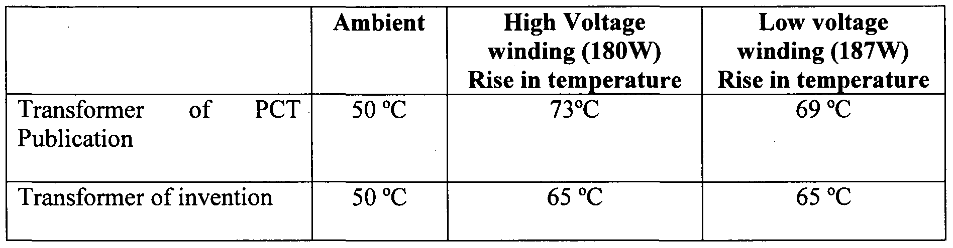
The reduced rise in temperature in the windings of the transformer of the invention as seen in Table 2 is significant and consequential in the actual operating conditions of a transformer as reduction in the rise in temperature of even such magnitude improves the cooling efficiency and performance of the transformer.
The transformer can be two phase also and there can be more than two first and second heat pipes depending upon the rating of the transformer. The electric insulation layers are formed by electric grade plastic films. The covers and inner and outer jackets are made of materials having good thermal conductivity and are preferably made of aluminium. They have preferably thickness of 2 to 5 mm. Any known resin is used for encapsulation of the transformer. Preferably the resin is polycrete.
Claims
1. An improved compact dry transformer comprising a magnetic material core and a coil assembly assembled onto the core, the core comprising heat dissipating covers with cooling fins snug fitted over the core, the covers being made of non-magnetic material having good thermal conductivity, the coil assembly comprising a low voltage winding and a high voltage winding with electric insulation layers between the layers of conductors of each of the windings and between the windings, the coil assembly being mounted on the core over a heat dissipating inner jacket made of non-magnetic material having good thermal conductivity in close contact with the inner jacket, the inner jacket having a slit along the length thereof, atleast one first heat pipe located between the core and inner jacket in close contact therewith, the first heat pipe protruding out of the coil assembly and being provided with cooling fins at the protruding thereof, the coil assembly further comprising a heat dissipating outer jacket made of non-magnetic material having good thermal conductivity snug fitted over the high voltage winding, the outer jacket being provided with a slit along the length thereof, atleast one second heat pipe located against the outer jacket in close contact therewith, the coil assembly with the outer jacket and second heat pipe being encapsulated with a resin casting with the second heat pipe protruding out of bushings cast with the resin casting, the protruding outer end of the second heat pipe being isolated from the ground potential by the bushings and provided with cooling fins, the terminals of the transformer being located in the bushings and connected to the windings ends.
Priority Applications (3)
| Application Number | Priority Date | Filing Date | Title |
|---|---|---|---|
| EP08720134A EP2115753A1 (en) | 2008-02-22 | 2008-02-22 | Improved compact dry transformer |
| US12/520,509 US7907039B2 (en) | 2008-02-22 | 2008-02-22 | Compact dry transformer |
| PCT/IN2008/000104 WO2009104197A1 (en) | 2008-02-22 | 2008-02-22 | Improved compact dry transformer |
Applications Claiming Priority (1)
| Application Number | Priority Date | Filing Date | Title |
|---|---|---|---|
| PCT/IN2008/000104 WO2009104197A1 (en) | 2008-02-22 | 2008-02-22 | Improved compact dry transformer |
Publications (1)
| Publication Number | Publication Date |
|---|---|
| WO2009104197A1 true WO2009104197A1 (en) | 2009-08-27 |
Family
ID=40985111
Family Applications (1)
| Application Number | Title | Priority Date | Filing Date |
|---|---|---|---|
| PCT/IN2008/000104 WO2009104197A1 (en) | 2008-02-22 | 2008-02-22 | Improved compact dry transformer |
Country Status (3)
| Country | Link |
|---|---|
| US (1) | US7907039B2 (en) |
| EP (1) | EP2115753A1 (en) |
| WO (1) | WO2009104197A1 (en) |
Cited By (4)
| Publication number | Priority date | Publication date | Assignee | Title |
|---|---|---|---|---|
| WO2011126991A1 (en) * | 2010-04-07 | 2011-10-13 | Abb Technology Ag | Outdoor dry-type transformer |
| EP2402698A1 (en) * | 2010-07-01 | 2012-01-04 | ABB Technology AG | Method for monitoring the functions of and/or controlling a coolant system and coolant system |
| WO2017046627A1 (en) * | 2015-09-14 | 2017-03-23 | Appleton Grp, Llc | An arrangement for maintaining desired temperature conditions in an encapsulated transformer |
| CN110993330A (en) * | 2019-10-31 | 2020-04-10 | 广州市一变电气设备有限公司 | Manufacturing method of transformer coil and oven device |
Families Citing this family (3)
| Publication number | Priority date | Publication date | Assignee | Title |
|---|---|---|---|---|
| EP2645379A1 (en) * | 2012-09-19 | 2013-10-02 | ABB Technology Ltd | Electrical insulator bushing |
| JP6081181B2 (en) * | 2012-12-18 | 2017-02-15 | 新電元工業株式会社 | Transformer core and transformer |
| US10147531B2 (en) | 2015-02-26 | 2018-12-04 | Lear Corporation | Cooling method for planar electrical power transformer |
Citations (4)
| Publication number | Priority date | Publication date | Assignee | Title |
|---|---|---|---|---|
| US3243744A (en) * | 1960-08-03 | 1966-03-29 | Fed Pacific Electric Co | Toroidal core electrical transformer with cooling fins |
| JPS56162810A (en) * | 1980-05-20 | 1981-12-15 | Matsushita Electric Ind Co Ltd | Molded coil |
| JP2000223323A (en) * | 1999-02-01 | 2000-08-11 | Toshiba Corp | Stationary induction apparatus |
| WO2006016377A1 (en) * | 2004-08-10 | 2006-02-16 | Crompton Greaves Limited | Compact dry transformer |
Family Cites Families (6)
| Publication number | Priority date | Publication date | Assignee | Title |
|---|---|---|---|---|
| US3551863A (en) * | 1968-03-18 | 1970-12-29 | Louis L Marton | Transformer with heat dissipator |
| JP3279521B2 (en) * | 1998-02-28 | 2002-04-30 | 三星電子株式会社 | Microwave oven high voltage transformer with heat dissipation structure |
| DE69922094T2 (en) * | 1998-07-31 | 2005-12-01 | Hitachi, Ltd. | Transformer core made of amorphous metal |
| US6563410B1 (en) * | 2000-11-16 | 2003-05-13 | Louis L. Marton | Small footprint power transformer incorporating improved heat dissipation means |
| AU2003203619A1 (en) * | 2002-04-23 | 2003-11-06 | Puretec Co., Ltd | Method and device for cooling high voltage transformer for microwave oven |
| DE102004021107A1 (en) * | 2004-04-29 | 2005-11-24 | Bosch Rexroth Ag | Liquid cooling for iron core and winding packages |
-
2008
- 2008-02-22 US US12/520,509 patent/US7907039B2/en not_active Expired - Fee Related
- 2008-02-22 WO PCT/IN2008/000104 patent/WO2009104197A1/en active Application Filing
- 2008-02-22 EP EP08720134A patent/EP2115753A1/en not_active Withdrawn
Patent Citations (4)
| Publication number | Priority date | Publication date | Assignee | Title |
|---|---|---|---|---|
| US3243744A (en) * | 1960-08-03 | 1966-03-29 | Fed Pacific Electric Co | Toroidal core electrical transformer with cooling fins |
| JPS56162810A (en) * | 1980-05-20 | 1981-12-15 | Matsushita Electric Ind Co Ltd | Molded coil |
| JP2000223323A (en) * | 1999-02-01 | 2000-08-11 | Toshiba Corp | Stationary induction apparatus |
| WO2006016377A1 (en) * | 2004-08-10 | 2006-02-16 | Crompton Greaves Limited | Compact dry transformer |
Cited By (9)
| Publication number | Priority date | Publication date | Assignee | Title |
|---|---|---|---|---|
| WO2011126991A1 (en) * | 2010-04-07 | 2011-10-13 | Abb Technology Ag | Outdoor dry-type transformer |
| CN103026432A (en) * | 2010-04-07 | 2013-04-03 | Abb技术有限公司 | Outdoor dry-type transformer |
| US9640314B2 (en) | 2010-04-07 | 2017-05-02 | Abb Schweiz Ag | Outdoor dry-type transformer |
| EP2402698A1 (en) * | 2010-07-01 | 2012-01-04 | ABB Technology AG | Method for monitoring the functions of and/or controlling a coolant system and coolant system |
| CN102313471A (en) * | 2010-07-01 | 2012-01-11 | Abb技术有限公司 | The function supervision of cooling system and/or control method and corresponding cooling |
| US9520221B2 (en) | 2010-07-01 | 2016-12-13 | Abb Schweiz Ag | Method for function monitoring and/or control of a cooling system, and a corresponding cooling system |
| WO2017046627A1 (en) * | 2015-09-14 | 2017-03-23 | Appleton Grp, Llc | An arrangement for maintaining desired temperature conditions in an encapsulated transformer |
| US10840003B2 (en) | 2015-09-14 | 2020-11-17 | Appleton Grp Llc | Arrangement for maintaining desired temperature conditions in an encapsulated transformer |
| CN110993330A (en) * | 2019-10-31 | 2020-04-10 | 广州市一变电气设备有限公司 | Manufacturing method of transformer coil and oven device |
Also Published As
| Publication number | Publication date |
|---|---|
| US20100328002A1 (en) | 2010-12-30 |
| US7907039B2 (en) | 2011-03-15 |
| EP2115753A1 (en) | 2009-11-11 |
Similar Documents
| Publication | Publication Date | Title |
|---|---|---|
| US7369024B2 (en) | Compact dry transformer | |
| US7907039B2 (en) | Compact dry transformer | |
| Liu et al. | Thermal management and cooling of windings in electrical machines for electric vehicle and traction application | |
| RU2681643C1 (en) | Cable fittings for connecting a high-voltage cable with a high-voltage component | |
| EP2929551B1 (en) | Transformer assembly | |
| US20220190686A1 (en) | Electrical machine winding having improved colling | |
| EP3158567B1 (en) | Inductor assembly comprising at least one inductor coil thermally coupled to a metallic inductor housing | |
| US6917272B2 (en) | Electric device | |
| US3614693A (en) | Liquid cooling of electrical apparatus | |
| CA2954315C (en) | Electrical component having an electrically conductive central element | |
| KR20070075840A (en) | Waterproofing terminal of distribution transformer | |
| KR101114995B1 (en) | Compact transformer using heat exhaust means | |
| EP1224673B1 (en) | Earth cooled distribution transformer system and method | |
| EP3780034B1 (en) | A non-liquid immersed transformer | |
| EP3780035B1 (en) | A non-liquid immersed transformer | |
| CN206225277U (en) | A kind of anti-overheat vacuum circuit breaker | |
| US6031722A (en) | Earth cooled distribution transformer system and method | |
| CN207542054U (en) | A kind of dry-type transformer | |
| CN201877239U (en) | Integral high-power high-frequency transformer | |
| CN203922422U (en) | Lifting electromagnet | |
| US20230121301A1 (en) | Thermal conductive bobbin for a magnetic power unit | |
| KR200486562Y1 (en) | Oil immersed transformer having magnetic shield | |
| EP3402039A1 (en) | Insulation of an electric machine | |
| JP2011155117A (en) | Heat dissipation structure of coil | |
| PL73320Y1 (en) | Magnetic element housing |
Legal Events
| Date | Code | Title | Description |
|---|---|---|---|
| WWE | Wipo information: entry into national phase |
Ref document number: 2008720134 Country of ref document: EP |
|
| WWE | Wipo information: entry into national phase |
Ref document number: 12520509 Country of ref document: US |
|
| 121 | Ep: the epo has been informed by wipo that ep was designated in this application |
Ref document number: 08720134 Country of ref document: EP Kind code of ref document: A1 |
|
| NENP | Non-entry into the national phase |
Ref country code: DE |