WO2009093636A1 - Corrugated retainer for ball bearing, and deep groove ball bearing - Google Patents
Corrugated retainer for ball bearing, and deep groove ball bearing Download PDFInfo
- Publication number
- WO2009093636A1 WO2009093636A1 PCT/JP2009/050940 JP2009050940W WO2009093636A1 WO 2009093636 A1 WO2009093636 A1 WO 2009093636A1 JP 2009050940 W JP2009050940 W JP 2009050940W WO 2009093636 A1 WO2009093636 A1 WO 2009093636A1
- Authority
- WO
- WIPO (PCT)
- Prior art keywords
- ball bearing
- groove
- deep groove
- cage
- corrugated cage
- Prior art date
Links
Images


Classifications
-
- F—MECHANICAL ENGINEERING; LIGHTING; HEATING; WEAPONS; BLASTING
- F16—ENGINEERING ELEMENTS AND UNITS; GENERAL MEASURES FOR PRODUCING AND MAINTAINING EFFECTIVE FUNCTIONING OF MACHINES OR INSTALLATIONS; THERMAL INSULATION IN GENERAL
- F16C—SHAFTS; FLEXIBLE SHAFTS; ELEMENTS OR CRANKSHAFT MECHANISMS; ROTARY BODIES OTHER THAN GEARING ELEMENTS; BEARINGS
- F16C19/00—Bearings with rolling contact, for exclusively rotary movement
- F16C19/02—Bearings with rolling contact, for exclusively rotary movement with bearing balls essentially of the same size in one or more circular rows
- F16C19/14—Bearings with rolling contact, for exclusively rotary movement with bearing balls essentially of the same size in one or more circular rows for both radial and axial load
- F16C19/16—Bearings with rolling contact, for exclusively rotary movement with bearing balls essentially of the same size in one or more circular rows for both radial and axial load with a single row of balls
- F16C19/163—Bearings with rolling contact, for exclusively rotary movement with bearing balls essentially of the same size in one or more circular rows for both radial and axial load with a single row of balls with angular contact
-
- F—MECHANICAL ENGINEERING; LIGHTING; HEATING; WEAPONS; BLASTING
- F16—ENGINEERING ELEMENTS AND UNITS; GENERAL MEASURES FOR PRODUCING AND MAINTAINING EFFECTIVE FUNCTIONING OF MACHINES OR INSTALLATIONS; THERMAL INSULATION IN GENERAL
- F16C—SHAFTS; FLEXIBLE SHAFTS; ELEMENTS OR CRANKSHAFT MECHANISMS; ROTARY BODIES OTHER THAN GEARING ELEMENTS; BEARINGS
- F16C33/00—Parts of bearings; Special methods for making bearings or parts thereof
- F16C33/30—Parts of ball or roller bearings
- F16C33/38—Ball cages
- F16C33/3837—Massive or moulded cages having cage pockets surrounding the balls, e.g. machined window cages
- F16C33/3862—Massive or moulded cages having cage pockets surrounding the balls, e.g. machined window cages comprising two annular parts joined together
- F16C33/3875—Massive or moulded cages having cage pockets surrounding the balls, e.g. machined window cages comprising two annular parts joined together made from plastic, e.g. two injection moulded parts joined by a snap fit
-
- F—MECHANICAL ENGINEERING; LIGHTING; HEATING; WEAPONS; BLASTING
- F16—ENGINEERING ELEMENTS AND UNITS; GENERAL MEASURES FOR PRODUCING AND MAINTAINING EFFECTIVE FUNCTIONING OF MACHINES OR INSTALLATIONS; THERMAL INSULATION IN GENERAL
- F16C—SHAFTS; FLEXIBLE SHAFTS; ELEMENTS OR CRANKSHAFT MECHANISMS; ROTARY BODIES OTHER THAN GEARING ELEMENTS; BEARINGS
- F16C33/00—Parts of bearings; Special methods for making bearings or parts thereof
- F16C33/30—Parts of ball or roller bearings
- F16C33/38—Ball cages
- F16C33/42—Ball cages made from wire or sheet metal strips
- F16C33/422—Ball cages made from wire or sheet metal strips made from sheet metal
- F16C33/427—Ball cages made from wire or sheet metal strips made from sheet metal from two parts, e.g. ribbon cages with two corrugated annular parts
-
- F—MECHANICAL ENGINEERING; LIGHTING; HEATING; WEAPONS; BLASTING
- F16—ENGINEERING ELEMENTS AND UNITS; GENERAL MEASURES FOR PRODUCING AND MAINTAINING EFFECTIVE FUNCTIONING OF MACHINES OR INSTALLATIONS; THERMAL INSULATION IN GENERAL
- F16C—SHAFTS; FLEXIBLE SHAFTS; ELEMENTS OR CRANKSHAFT MECHANISMS; ROTARY BODIES OTHER THAN GEARING ELEMENTS; BEARINGS
- F16C2226/00—Joining parts; Fastening; Assembling or mounting parts
- F16C2226/50—Positive connections
- F16C2226/70—Positive connections with complementary interlocking parts
- F16C2226/74—Positive connections with complementary interlocking parts with snap-fit, e.g. by clips
Definitions
- the present invention relates to a corrugated cage for ball bearings and a deep groove ball bearing in which a hemispherical pocket portion for holding a ball and a pair of annular bodies in which the connecting portions are alternately provided are connected by a connecting portion.
- a hemispherical pocket portion for holding the balls and a connecting portion for connecting these pocket portions are arranged in the radial direction.
- a pair of annular bodies provided alternately on an annular belt having a width uses a corrugated cage in which the circumferential positions of the pocket portions are matched with each other and the opposing connecting portions are coupled to each other (for example, patents) References 1 and 2).
- a pair of annular bodies of a corrugated cage is formed by press molding of a metal plate, and these connecting portions are coupled with rivets.
- annular body was formed by injection molding of resin, and the connection parts were couple
- the annular body of these corrugated cages is formed in a uniform band width in which the band width dimensions of the pocket portion and the connecting portion are equal.
- Deep groove ball bearings using corrugated cages such as those described above are subject to sudden loads due to vibration, etc., as in the case of bearing devices such as electrical equipment and transmissions mounted on automobiles.
- bearing devices such as electrical equipment and transmissions mounted on automobiles.
- measures may be taken to make the raceway groove deeper and raise the groove shoulder to make it difficult for the ball to ride on the groove shoulder.
- the circumferential center of the pocket portion of the corrugated cage extends in the axial direction of the deep groove ball bearing along the outer surface of the ball.
- the corrugated cage is tilted from the axial orthogonal cross-section due to deviation from the center, there is a problem that the central portion in the circumferential direction of the pocket portion interferes with the groove shoulder of the raceway groove at the band width end portion.
- the object of the present invention is to secure the strength of the connecting portion of the corrugated cage and prevent the center portion in the circumferential direction of the pocket portion from interfering with the groove shoulder even if the groove shoulder of the raceway groove is increased. That is.
- a corrugated cage for ball bearings includes a hemispherical pocket for holding a plurality of balls arranged between the inner ring and the outer raceway groove of the deep groove ball bearing, and these A pair of annular bodies provided alternately with annular bands having a width in the radial direction and coupling portions that connect the pocket portions are joined together by matching the circumferential positions of the pocket portions with each other.
- the band width dimension of the center part in the circumferential direction of the pocket part of the pair of annular bodies is made smaller than the band width dimension of the connecting part.
- the width of the central portion in the circumferential direction of the pocket portions of the pair of annular bodies is made smaller than the width of the connecting portion, thereby ensuring the strength of the connecting portion of the corrugated cage, and the raceway groove.
- the height of the shoulder of the pocket was set so that the pocket did not interfere with the shoulder.
- the circumferential direction end portion and the connecting portion of the pocket portion do not extend so much in the axial direction of the deep groove ball bearing, even when the band width dimension is increased, when the corrugated cage is inclined from the axial orthogonal section, There is no interference with the groove shoulder of the raceway groove.
- the annular body may be formed by press forming a metal plate.
- the metal plate is a low carbon steel plate having a Ti content of 0.0050 mass% or less, preferably 0.0015 mass% or less and a C content of 0.25 mass% or less.
- the Ti content of the low carbon steel sheet is 0.0050% by mass or less, preferably 0.0015% by mass or less, because Ti in the steel reacts with nitrogen entering from the surface during the salt bath soft nitriding treatment, This is for preventing TiN from precipitating excessively and causing the steel to become brittle.
- the annular body may be formed by resin injection molding.
- the deep groove ball bearing of the present invention employs a configuration in which any of the ball bearing cages described above holds a plurality of balls arranged between the race grooves of the inner ring and the outer ring.
- the deep groove ball bearing is suitable for a bearing device used in an automobile.
- the band width dimension of the center portion in the circumferential direction of the pocket portions of the pair of annular bodies of the corrugated cage is made smaller than the band width dimension of the coupling section, so the strength of the coupling section It is possible to prevent the pocket portion from interfering with the groove shoulder even if the groove shoulder of the raceway groove is raised while securing the above.
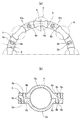
- Longitudinal side view showing the deep groove ball bearing of the first embodiment a is a front view of the waveform holder of FIG. 1, and b is a sectional view taken along line IIb-IIb of a.
- 1 is a longitudinal sectional view showing a transmission using the deep groove ball bearing of FIG.
- Longitudinal side view showing the deep groove ball bearing of the second embodiment a is a front view of the waveform holder of FIG. 4, and b is a cross-sectional view taken along the line Vb-Vb of a.
- this deep groove ball bearing 1 is configured by holding a plurality of balls 4 arranged between raceway grooves 2a and 3a of an inner ring 2 and an outer ring 3 with a corrugated cage 5, and each raceway groove 2a.
- the depth of 3a is made deeper than that of the standard product, so that the groove shoulder is formed high, and it is difficult for the ball 4 to ride on the groove shoulder.
- the corrugated cage 5 includes a pair of hemispherical pocket portions 6a and a connecting portion 6b provided alternately in an annular band having a radial width.
- the annular body 6 is obtained by matching the circumferential positions of the pocket portions 6a with each other and connecting the opposing connecting portions 6b with the rivets 7, and the band width dimension A at the center portion in the circumferential direction of the pocket portions 6a is: It is formed smaller than the width B of the connecting portion 6b.
- the band width dimension B of the connecting portion 6b is smaller than the dimensional difference H shown in FIG. 1 between the inner diameter of the shoulder of the raceway groove 3a of the outer ring 3 and the outer diameter of the shoulder of the raceway groove 2a of the inner ring 2.
- the size difference H is approached.
- Each of the annular bodies 6 is made of a low carbon steel plate made of aluminum killed steel having a Ti content of 0.0015% by mass or less and a C content of 0.25% by mass or less. Then, a salt bath soft nitriding treatment is performed to form a nitride layer on the surface.
- the low-carbon steel plate may be rimmed steel, semi-killed steel, or silicon-killed steel.
- FIG. 3 shows an automobile transmission using the deep groove ball bearing 1 described above.
- This transmission is a manual type, and an input shaft 12, an output shaft 13, and a pilot shaft 14 as an intermediate shaft are arranged in series in a housing 11, and a counter shaft 15 and a reverse shaft 16 as intermediate shafts are output. It is arranged in parallel with the shaft 13. Note that FIG. 3 is expanded and displayed for easy viewing of the drawing, and the reverse shaft 16 is also engaged with the output shaft 13.
- Each of the shafts 12, 13, 14, 15 and 16 is provided with a large number of gear groups. By changing the meshing of these gear groups by a clutch hub 17 which is shifted by an external operation, the input is changed. A torque transmission path from the shaft 12 to the output shaft 13 is appropriately selected. In this transmission, an input shaft 12, an output shaft 13, a pilot shaft 14, a counter shaft 15, and a gear member 18 attached to one end side of the counter shaft 15 are supported by the deep groove ball bearing 1.
- the deep groove ball bearing 1 has the same basic configuration as that of the first embodiment, and a pair of annular bodies 6 of the corrugated cage 5 are formed by resin injection molding, and the annular bodies 6 face each other.
- the connecting portions 6b are different from each other in that the engaging holes 8a and the engaging claws 8b are engaged with each other.
- the other portions are the same as those of the first embodiment, and the band width dimension A at the central portion in the circumferential direction of the pocket portion 6a is formed smaller than the band width dimension B of the connecting portion 6b.
Landscapes
- Engineering & Computer Science (AREA)
- General Engineering & Computer Science (AREA)
- Mechanical Engineering (AREA)
- Rolling Contact Bearings (AREA)
Abstract
Disclosed is a corrugated retainer, in which the strength of a connecting portion is retained and in which the circumferential center of a pocket portion is prevented from interfering with the groove shoulder of a raceway groove even if the groove shoulder is made high. The band-width size (A) of the circumferential center of the pocket portion (6a) of a pair of annular members (6) is made smaller than the band-width size (B) of a connecting portion (6b). Thus, the intensity of the connecting portion (6b) of a corrugated retainer (5) is retained, and the pocket portion (6a) is prevented from interfering with the groove shoulder, even if the groove shoulder of the raceway groove of a deep groove ball bearing is made high.
Description
本発明は、ボールを保持する半球状のポケット部とその連結部が交互に設けられた一対の環状体を連結部で結合した玉軸受用波形保持器と深溝玉軸受に関する。
The present invention relates to a corrugated cage for ball bearings and a deep groove ball bearing in which a hemispherical pocket portion for holding a ball and a pair of annular bodies in which the connecting portions are alternately provided are connected by a connecting portion.
内輪と外輪の軌道溝間に配列した複数のボールを保持器で保持した深溝玉軸受には、ボールを保持する半球状のポケット部と、これらのポケット部を連結する連結部とを半径方向の幅を有する環状の帯に交互に設けた一対の環状体を、ポケット部の周方向位置を互いに合致させて、対向する連結部同士を結合した波形保持器を用いたものがある(例えば、特許文献1、2参照)。
In a deep groove ball bearing in which a plurality of balls arranged between the inner and outer raceway grooves are held by a cage, a hemispherical pocket portion for holding the balls and a connecting portion for connecting these pocket portions are arranged in the radial direction. A pair of annular bodies provided alternately on an annular belt having a width uses a corrugated cage in which the circumferential positions of the pocket portions are matched with each other and the opposing connecting portions are coupled to each other (for example, patents) References 1 and 2).
特許文献1に記載されたものでは、波形保持器の一対の環状体を金属板のプレス成形で形成し、これらの連結部同士をリベットで結合している。また、特許文献2に記載されたものでは、一対の環状体を樹脂の射出成形で形成し、連結部同士を係合孔と係合爪の係合で結合している。従来、これらの波形保持器の環状体は、ポケット部と連結部の帯幅寸法が等しい均一な帯幅に形成されている。
In the one described in Patent Document 1, a pair of annular bodies of a corrugated cage is formed by press molding of a metal plate, and these connecting portions are coupled with rivets. Moreover, in what was described in patent document 2, a pair of cyclic | annular body was formed by injection molding of resin, and the connection parts were couple | bonded by engagement of the engagement hole and the engagement nail | claw. Conventionally, the annular body of these corrugated cages is formed in a uniform band width in which the band width dimensions of the pocket portion and the connecting portion are equal.
上述したような波形保持器を用いた深溝玉軸受は、自動車に搭載される電装補機やトランスミッション等の軸受装置のように、振動等による急激な荷重が負荷されたり、アキシアル方向のモーメント荷重が負荷される用途に使用されると、ボールが内輪や外輪の軌道溝の肩に乗り上げる不具合が発生することがある。このような不具合を防止するために、軌道溝を深くして溝肩を高くし、ボールが溝肩に乗り上げ難くする対策を採ることがある。
Deep groove ball bearings using corrugated cages such as those described above are subject to sudden loads due to vibration, etc., as in the case of bearing devices such as electrical equipment and transmissions mounted on automobiles. When used in a loaded application, there may be a problem that the ball rides on the shoulder of the raceway groove of the inner ring or the outer ring. In order to prevent such a problem, measures may be taken to make the raceway groove deeper and raise the groove shoulder to make it difficult for the ball to ride on the groove shoulder.
このように軌道溝の溝肩を高くすると、波形保持器のポケット部の円周方向中央部は、ボールの外表面に沿って深溝玉軸受の軸方向に拡がっているので、ボールの軌道溝中心からのずれ等によって、波形保持器が軸直交断面から傾くと、ポケット部の円周方向中央部が帯幅端部で軌道溝の溝肩と干渉する問題がある。このポケット部の円周方向中央部が溝肩と干渉するのを防止するためには、一対の環状体の帯幅寸法を小さくすればよいが、従来の均一な帯幅の環状体は、連結部の帯幅寸法が小さくなって、リベットや係合孔と係合爪との係合で結合される連結部の強度を確保できなくなる問題がある。
When the groove shoulder of the raceway groove is increased in this way, the circumferential center of the pocket portion of the corrugated cage extends in the axial direction of the deep groove ball bearing along the outer surface of the ball. When the corrugated cage is tilted from the axial orthogonal cross-section due to deviation from the center, there is a problem that the central portion in the circumferential direction of the pocket portion interferes with the groove shoulder of the raceway groove at the band width end portion. In order to prevent the circumferential central portion of the pocket portion from interfering with the groove shoulder, it is only necessary to reduce the band width of the pair of annular bodies. There is a problem that the band width dimension of the portion becomes small, and the strength of the connecting portion coupled by the engagement between the rivet or the engagement hole and the engagement claw cannot be secured.
そこで、本発明の課題は、波形保持器の連結部の強度を確保した上で、軌道溝の溝肩を高くしても、ポケット部の円周方向中央部が溝肩と干渉しないようにすることである。
Therefore, the object of the present invention is to secure the strength of the connecting portion of the corrugated cage and prevent the center portion in the circumferential direction of the pocket portion from interfering with the groove shoulder even if the groove shoulder of the raceway groove is increased. That is.
上記の課題を解決するために、本発明の玉軸受用波形保持器は、深溝玉軸受の内輪と外輪の軌道溝間に配列される複数のボールを保持する半球状のポケット部と、これらのポケット部を連結する連結部とを半径方向の幅を有する環状の帯に交互に設けた一対の環状体を、前記ポケット部の周方向位置を互いに合致させて、対向する前記連結部同士を結合した玉軸受用波形保持器において、前記一対の環状体の前記ポケット部の円周方向中央部の帯幅寸法を、前記連結部の帯幅寸法よりも小さくした構成を採用した。
In order to solve the above problems, a corrugated cage for ball bearings according to the present invention includes a hemispherical pocket for holding a plurality of balls arranged between the inner ring and the outer raceway groove of the deep groove ball bearing, and these A pair of annular bodies provided alternately with annular bands having a width in the radial direction and coupling portions that connect the pocket portions are joined together by matching the circumferential positions of the pocket portions with each other. In the ball bearing corrugated cage, the band width dimension of the center part in the circumferential direction of the pocket part of the pair of annular bodies is made smaller than the band width dimension of the connecting part.
すなわち、一対の環状体のポケット部の円周方向中央部の帯幅寸法を、連結部の帯幅寸法よりも小さくすることにより、波形保持器の連結部の強度を確保した上で、軌道溝の溝肩を高くしても、ポケット部が溝肩と干渉しないようにした。なお、ポケット部の円周方向端部と連結部は、深溝玉軸受の軸方向にあまり拡がっていないので、帯幅寸法を大きくしても、波形保持器が軸直交断面から傾いたときに、軌道溝の溝肩と干渉することはない。
That is, the width of the central portion in the circumferential direction of the pocket portions of the pair of annular bodies is made smaller than the width of the connecting portion, thereby ensuring the strength of the connecting portion of the corrugated cage, and the raceway groove. The height of the shoulder of the pocket was set so that the pocket did not interfere with the shoulder. In addition, since the circumferential direction end portion and the connecting portion of the pocket portion do not extend so much in the axial direction of the deep groove ball bearing, even when the band width dimension is increased, when the corrugated cage is inclined from the axial orthogonal section, There is no interference with the groove shoulder of the raceway groove.
前記連結部の帯幅寸法を、前記外輪の軌道溝の溝肩の内径と前記内輪の軌道溝の溝肩の外径との寸法差よりも小さくした範囲でこの寸法差に近づけることにより、連結部の強度を十分に確保することができる。
By connecting the band width dimension of the connecting portion closer to this dimensional difference in a range smaller than the dimensional difference between the inner diameter of the groove shoulder of the outer ring raceway groove and the outer diameter of the shoulder groove of the inner ring raceway groove, The strength of the part can be sufficiently secured.
前記環状体は、金属板のプレス成形で形成したものとすることができる。
The annular body may be formed by press forming a metal plate.
前記金属板を、Ti含有量が0.0050質量%以下、好ましくは0.0015質量%以下で、C含有量が0.25質量%以下の低炭素鋼板とし、この低炭素鋼板に塩浴軟窒化処理を施すことにより、環状体のプレス成形性を加工性の優れた低炭素鋼板によって確保した上で、帯幅寸法が小さくなって、ボールとの接触面圧が高くなるポケット部の耐摩耗性を、塩浴軟窒化処理で形成される表面の窒化層によって確保することができる。なお、低炭素鋼板のTi含有量を0.0050質量%以下、好ましくは0.0015質量%以下としたのは、鋼中のTiが塩浴軟窒化処理時に表面から侵入する窒素と反応し、TiNが過剰に析出して鋼が脆化するのを防止するためである。
The metal plate is a low carbon steel plate having a Ti content of 0.0050 mass% or less, preferably 0.0015 mass% or less and a C content of 0.25 mass% or less. By applying nitriding treatment, the press formability of the annular body is ensured by a low-carbon steel plate with excellent workability, and the wear resistance of the pocket part that reduces the width of the band and increases the contact pressure with the ball Can be ensured by the nitrided layer on the surface formed by the salt bath soft nitriding treatment. The Ti content of the low carbon steel sheet is 0.0050% by mass or less, preferably 0.0015% by mass or less, because Ti in the steel reacts with nitrogen entering from the surface during the salt bath soft nitriding treatment, This is for preventing TiN from precipitating excessively and causing the steel to become brittle.
前記環状体は、樹脂の射出成形で形成したものとすることもできる。
The annular body may be formed by resin injection molding.
また、本発明の深溝玉軸受は、上述したいずれかの玉軸受用保持器で、内輪と外輪の軌道溝間に配列された複数のボールを保持した構成を採用した。
Further, the deep groove ball bearing of the present invention employs a configuration in which any of the ball bearing cages described above holds a plurality of balls arranged between the race grooves of the inner ring and the outer ring.
前記深溝玉軸受は、自動車に搭載される軸受装置に使用されるものに好適である。
The deep groove ball bearing is suitable for a bearing device used in an automobile.
本発明の玉軸受用波形保持器は、波形保持器の一対の環状体のポケット部の円周方向中央部の帯幅寸法を、連結部の帯幅寸法よりも小さくしたので、連結部の強度を確保した上で、軌道溝の溝肩を高くしても、ポケット部が溝肩と干渉しないようにすることができる。
In the corrugated cage for ball bearings of the present invention, the band width dimension of the center portion in the circumferential direction of the pocket portions of the pair of annular bodies of the corrugated cage is made smaller than the band width dimension of the coupling section, so the strength of the coupling section It is possible to prevent the pocket portion from interfering with the groove shoulder even if the groove shoulder of the raceway groove is raised while securing the above.
前記連結部の帯幅寸法を、外輪の軌道溝の溝肩の内径と前記内輪の軌道溝の溝肩の外径との寸法差よりも小さくした範囲でこの寸法差に近づけることにより、連結部の強度を十分に確保することができる。
By bringing the width of the connecting portion closer to this dimensional difference in a range smaller than the dimensional difference between the inner diameter of the groove shoulder of the outer ring raceway groove and the outer diameter of the groove shoulder of the inner ring raceway groove, It is possible to ensure sufficient strength.
1 深溝玉軸受
2 内輪
3 外輪
2a、3a 軌道溝
4 ボール
5 波形保持器
6 環状体
6a ポケット部
7 リベット
8a 係合孔
8b 係合爪
11 ハウジング
12 インプットシャフト
13 アウトプットシャフト
14 パイロットシャフト
15 カウンターシャフト
16 リバースシャフト
17 クラッチハブ
18 ギヤ部材 DESCRIPTION OFSYMBOLS 1 Deep groove ball bearing 2 Inner ring 3 Outer ring 2a, 3a Track groove 4 Ball 5 Corrugated retainer 6 Annulus 6a Pocket part 7 Rivet 8a Engagement hole 8b Engagement claw 11 Housing 12 Input shaft 13 Output shaft 14 Pilot shaft 15 Counter shaft 16 Reverse shaft 17 Clutch hub 18 Gear member
2 内輪
3 外輪
2a、3a 軌道溝
4 ボール
5 波形保持器
6 環状体
6a ポケット部
7 リベット
8a 係合孔
8b 係合爪
11 ハウジング
12 インプットシャフト
13 アウトプットシャフト
14 パイロットシャフト
15 カウンターシャフト
16 リバースシャフト
17 クラッチハブ
18 ギヤ部材 DESCRIPTION OF
以下、図面に基づき、本発明の実施形態を説明する。図1乃至図3は、第1の実施形態を示す。図1に示すように、この深溝玉軸受1は、内輪2と外輪3の軌道溝2a、3a間に配列された複数のボール4を波形保持器5で保持したものであり、各軌道溝2a、3aの深さを標準品よりも深くして溝肩が高く形成され、ボール4が溝肩に乗り上げ難くなっている。
Hereinafter, embodiments of the present invention will be described with reference to the drawings. 1 to 3 show a first embodiment. As shown in FIG. 1, this deep groove ball bearing 1 is configured by holding a plurality of balls 4 arranged between raceway grooves 2a and 3a of an inner ring 2 and an outer ring 3 with a corrugated cage 5, and each raceway groove 2a. The depth of 3a is made deeper than that of the standard product, so that the groove shoulder is formed high, and it is difficult for the ball 4 to ride on the groove shoulder.
図2(a)、(b)に示すように、前記波形保持器5は、半球状のポケット部6aとその連結部6bが半径方向の幅を有する環状の帯に交互に設けられた一対の環状体6を、ポケット部6aの周方向位置を互いに合致させて、対向する連結部6b同士をリベット7で結合したものであり、ポケット部6aの円周方向中央部の帯幅寸法Aは、連結部6bの帯幅寸法Bよりも小さく形成されている。連結部6bの帯幅寸法Bは、図1に示した、外輪3の軌道溝3aの溝肩の内径と内輪2の軌道溝2aの溝肩の外径との寸法差Hよりも小さくした範囲でこの寸法差Hに近づけられている。
As shown in FIGS. 2 (a) and 2 (b), the corrugated cage 5 includes a pair of hemispherical pocket portions 6a and a connecting portion 6b provided alternately in an annular band having a radial width. The annular body 6 is obtained by matching the circumferential positions of the pocket portions 6a with each other and connecting the opposing connecting portions 6b with the rivets 7, and the band width dimension A at the center portion in the circumferential direction of the pocket portions 6a is: It is formed smaller than the width B of the connecting portion 6b. The band width dimension B of the connecting portion 6b is smaller than the dimensional difference H shown in FIG. 1 between the inner diameter of the shoulder of the raceway groove 3a of the outer ring 3 and the outer diameter of the shoulder of the raceway groove 2a of the inner ring 2. Thus, the size difference H is approached.
前記各環状体6は、Ti含有量が0.0015質量%以下で、C含有量が0.25質量%以下のアルミキルド鋼の低炭素鋼板を素材とし、円環状に打抜いたブランクをプレス成形した後、塩浴軟窒化処理を施して表面に窒化層を形成したものである。なお、素材の低炭素鋼板は、リムド鋼、セミキルド鋼またはシリコンキルド鋼としてもよい。
Each of the annular bodies 6 is made of a low carbon steel plate made of aluminum killed steel having a Ti content of 0.0015% by mass or less and a C content of 0.25% by mass or less. Then, a salt bath soft nitriding treatment is performed to form a nitride layer on the surface. Note that the low-carbon steel plate may be rimmed steel, semi-killed steel, or silicon-killed steel.
図3は、上述した深溝玉軸受1を使用した自動車のトランスミッションを示す。このトランスミッションは、マニュアル式のものであり、ハウジング11内にインプットシャフト12、アウトプットシャフト13および中間シャフトとしてのパイロットシャフト14が直列に配置され、さらに中間シャフトとしてのカウンターシャフト15とリバースシャフト16がアウトプットシャフト13と平行に配置されている。なお、図3は、図面を見やすくするために展開表示しており、リバースシャフト16はアウトプットシャフト13とも係合するようになっている。
FIG. 3 shows an automobile transmission using the deep groove ball bearing 1 described above. This transmission is a manual type, and an input shaft 12, an output shaft 13, and a pilot shaft 14 as an intermediate shaft are arranged in series in a housing 11, and a counter shaft 15 and a reverse shaft 16 as intermediate shafts are output. It is arranged in parallel with the shaft 13. Note that FIG. 3 is expanded and displayed for easy viewing of the drawing, and the reverse shaft 16 is also engaged with the output shaft 13.
前記各シャフト12、13、14、15、16には多数のギヤ群が設けられており、外部からの操作でシフトされるクラッチハブ17で、これらのギヤ群の噛み合わせを変えることにより、インプットシャフト12からアウトプットシャフト13へのトルク伝達経路が適切に選択されるようになっている。このトランスミッションでは、インプットシャフト12、アウトプットシャフト13、パイロットシャフト14、カウンターシャフト15、およびカウンターシャフト15の一端側に取り付けられたギヤ部材18が、前記深溝玉軸受1で支持されている。
Each of the shafts 12, 13, 14, 15 and 16 is provided with a large number of gear groups. By changing the meshing of these gear groups by a clutch hub 17 which is shifted by an external operation, the input is changed. A torque transmission path from the shaft 12 to the output shaft 13 is appropriately selected. In this transmission, an input shaft 12, an output shaft 13, a pilot shaft 14, a counter shaft 15, and a gear member 18 attached to one end side of the counter shaft 15 are supported by the deep groove ball bearing 1.
図4および図5(a)、(b)は、第2の実施形態を示す。この深溝玉軸受1は、基本的な構成は第1の実施形態のものと同じであり、前記波形保持器5の一対の環状体6が樹脂の射出成形で形成され、環状体6の対向する連結部6b同士が、係合孔8aと係合爪8bの係合で結合されている点が異なる。その他の部分は第1の実施形態のものと同じであり、ポケット部6aの円周方向中央部の帯幅寸法Aは、連結部6bの帯幅寸法Bよりも小さく形成されている。
4 and 5 (a) and 5 (b) show a second embodiment. The deep groove ball bearing 1 has the same basic configuration as that of the first embodiment, and a pair of annular bodies 6 of the corrugated cage 5 are formed by resin injection molding, and the annular bodies 6 face each other. The connecting portions 6b are different from each other in that the engaging holes 8a and the engaging claws 8b are engaged with each other. The other portions are the same as those of the first embodiment, and the band width dimension A at the central portion in the circumferential direction of the pocket portion 6a is formed smaller than the band width dimension B of the connecting portion 6b.
Claims (7)
- 深溝玉軸受の内輪と外輪の軌道溝間に配列される複数のボールを保持する半球状のポケット部と、これらのポケット部を連結する連結部とを半径方向の幅を有する環状の帯に交互に設けた一対の環状体を、前記ポケット部の周方向位置を互いに合致させて、対向する前記連結部同士を結合した玉軸受用波形保持器において、前記一対の環状体の前記ポケット部の円周方向中央部の帯幅寸法を、前記連結部の帯幅寸法よりも小さくしたことを特徴とする玉軸受用波形保持器。 The hemispherical pockets that hold a plurality of balls arranged between the inner and outer raceway grooves of the deep groove ball bearing and the connecting portions that connect these pockets are alternately formed into annular bands having a radial width. In the ball bearing corrugated cage in which the pair of annular bodies provided on the ball bearing corrugated cage is formed by matching the circumferential positions of the pocket portions to each other and connecting the opposing coupling portions, the circles of the pocket portions of the pair of annular bodies A corrugated cage for ball bearings, characterized in that a band width dimension at a central portion in the circumferential direction is made smaller than a band width dimension of the connecting portion.
- 前記連結部の帯幅寸法を、前記外輪の軌道溝の溝肩の内径と前記内輪の軌道溝の溝肩の外径との寸法差よりも小さくした範囲でこの寸法差に近づけた請求項1に記載の玉軸受用波形保持器。 The band width dimension of the connecting portion is close to the dimension difference within a range smaller than the dimension difference between the inner diameter of the groove shoulder of the outer ring raceway groove and the outer diameter of the groove shoulder of the inner ring raceway groove. The corrugated cage for ball bearings described in 1.
- 前記環状体を金属板のプレス成形で形成したものとした請求項1または2に記載の玉軸受用波形保持器。 The ball bearing corrugated cage according to claim 1 or 2, wherein the annular body is formed by press molding of a metal plate.
- 前記金属板を、Ti含有量が0.0050質量%以下で、C含有量が0.25質量%以下の低炭素鋼板とし、この低炭素鋼板に塩浴軟窒化処理を施した請求項3に記載の玉軸受用波形保持器。 The metal plate is a low carbon steel plate having a Ti content of 0.0050% by mass or less and a C content of 0.25% by mass or less, and the low carbon steel plate is subjected to salt bath soft nitriding treatment. Wave cage for ball bearings as described.
- 前記環状体を樹脂の射出成形で形成したものとした請求項1または2に記載の玉軸受用波形保持器。 The corrugated cage for ball bearings according to claim 1 or 2, wherein the annular body is formed by injection molding of resin.
- 請求項1乃至5のいずれかに記載の玉軸受用波形保持器で、内輪と外輪の軌道溝間に配列された複数のボールを保持したことを特徴とする深溝玉軸受。 A deep groove ball bearing characterized in that the ball cage corrugated cage according to any one of claims 1 to 5 holds a plurality of balls arranged between raceway grooves of an inner ring and an outer ring.
- 前記深溝玉軸受が、自動車に搭載される軸受装置に使用されるものである請求項6に記載の深溝玉軸受。 The deep groove ball bearing according to claim 6, wherein the deep groove ball bearing is used in a bearing device mounted on an automobile.
Applications Claiming Priority (2)
| Application Number | Priority Date | Filing Date | Title |
|---|---|---|---|
| JP2008-012473 | 2008-01-23 | ||
| JP2008012473A JP2009174605A (en) | 2008-01-23 | 2008-01-23 | Wavy cage for ball bearing, and deep groove ball bearing |
Publications (1)
| Publication Number | Publication Date |
|---|---|
| WO2009093636A1 true WO2009093636A1 (en) | 2009-07-30 |
Family
ID=40901142
Family Applications (1)
| Application Number | Title | Priority Date | Filing Date |
|---|---|---|---|
| PCT/JP2009/050940 WO2009093636A1 (en) | 2008-01-23 | 2009-01-22 | Corrugated retainer for ball bearing, and deep groove ball bearing |
Country Status (2)
| Country | Link |
|---|---|
| JP (1) | JP2009174605A (en) |
| WO (1) | WO2009093636A1 (en) |
Cited By (4)
| Publication number | Priority date | Publication date | Assignee | Title |
|---|---|---|---|---|
| DE102016221801A1 (en) * | 2016-11-08 | 2017-12-21 | Schaeffler Technologies AG & Co. KG | Rolling bearing cage and ball bearing with such a rolling bearing cage |
| CN112739923A (en) * | 2018-09-21 | 2021-04-30 | Ntn株式会社 | Retainer for ball bearing and rolling bearing |
| CN113614398A (en) * | 2019-03-22 | 2021-11-05 | Ntn株式会社 | Deep groove ball bearing |
| US11990661B2 (en) | 2018-12-28 | 2024-05-21 | Huawei Technologies Co., Ltd. | TM mode filter and method for manufacturing TM mode filter |
Families Citing this family (3)
| Publication number | Priority date | Publication date | Assignee | Title |
|---|---|---|---|---|
| JP2017044291A (en) * | 2015-08-28 | 2017-03-02 | Ntn株式会社 | Deep groove ball bearing |
| WO2020059829A1 (en) * | 2018-09-21 | 2020-03-26 | Ntn株式会社 | Ball bearing retainer and rolling bearing |
| JP2022135543A (en) * | 2021-03-05 | 2022-09-15 | Ntn株式会社 | Rolling bearing and cage for rolling bearing |
Citations (5)
| Publication number | Priority date | Publication date | Assignee | Title |
|---|---|---|---|---|
| JPH0649623A (en) * | 1992-07-30 | 1994-02-22 | Ntn Corp | Holder of rolling bearing subjected to tuftriding treatment |
| JP2001304268A (en) * | 2000-04-27 | 2001-10-31 | Koyo Seiko Co Ltd | Corrugated holder for rolling bearing |
| JP2006322564A (en) * | 2005-05-20 | 2006-11-30 | Ozak Seiko Co Ltd | Bearing |
| WO2007105354A1 (en) * | 2006-03-06 | 2007-09-20 | Ntn Corporation | Cage for ball bearing |
| JP2007333015A (en) * | 2006-06-13 | 2007-12-27 | Ntn Corp | Ball bearing |
-
2008
- 2008-01-23 JP JP2008012473A patent/JP2009174605A/en active Pending
-
2009
- 2009-01-22 WO PCT/JP2009/050940 patent/WO2009093636A1/en active Application Filing
Patent Citations (5)
| Publication number | Priority date | Publication date | Assignee | Title |
|---|---|---|---|---|
| JPH0649623A (en) * | 1992-07-30 | 1994-02-22 | Ntn Corp | Holder of rolling bearing subjected to tuftriding treatment |
| JP2001304268A (en) * | 2000-04-27 | 2001-10-31 | Koyo Seiko Co Ltd | Corrugated holder for rolling bearing |
| JP2006322564A (en) * | 2005-05-20 | 2006-11-30 | Ozak Seiko Co Ltd | Bearing |
| WO2007105354A1 (en) * | 2006-03-06 | 2007-09-20 | Ntn Corporation | Cage for ball bearing |
| JP2007333015A (en) * | 2006-06-13 | 2007-12-27 | Ntn Corp | Ball bearing |
Cited By (4)
| Publication number | Priority date | Publication date | Assignee | Title |
|---|---|---|---|---|
| DE102016221801A1 (en) * | 2016-11-08 | 2017-12-21 | Schaeffler Technologies AG & Co. KG | Rolling bearing cage and ball bearing with such a rolling bearing cage |
| CN112739923A (en) * | 2018-09-21 | 2021-04-30 | Ntn株式会社 | Retainer for ball bearing and rolling bearing |
| US11990661B2 (en) | 2018-12-28 | 2024-05-21 | Huawei Technologies Co., Ltd. | TM mode filter and method for manufacturing TM mode filter |
| CN113614398A (en) * | 2019-03-22 | 2021-11-05 | Ntn株式会社 | Deep groove ball bearing |
Also Published As
| Publication number | Publication date |
|---|---|
| JP2009174605A (en) | 2009-08-06 |
Similar Documents
| Publication | Publication Date | Title |
|---|---|---|
| WO2009093636A1 (en) | Corrugated retainer for ball bearing, and deep groove ball bearing | |
| JP2023082885A (en) | ball bearing | |
| US7513043B2 (en) | Support structure carrying thrust load of transmission, method of manufacturing thereof and thrust needle roller bearing | |
| US9145927B2 (en) | One-way clutch carrier assembly with bearing | |
| US9121456B2 (en) | One-way clutch carrier assembly | |
| US20060205560A1 (en) | Transmission unitary shell output carrier and ring gear | |
| EP2886900A1 (en) | Roller clutch equipped with support bearing | |
| WO2014208325A1 (en) | Method for manufacturing ribbon cage and ribbon cage | |
| CN104755276A (en) | Bearing for wheel, and bearing device for wheel | |
| JP2007032760A (en) | Constant velocity universal joint and its inside member | |
| JP2007333022A (en) | Deep groove ball bearing | |
| JP5372414B2 (en) | Tapered roller bearing | |
| JP2007263279A (en) | Retainer of rolling bearing | |
| JP2007292195A (en) | Deep groove ball bearing | |
| WO2009113252A1 (en) | Wheel bearing device | |
| CN110701193A (en) | Shaft for supporting rotating body, method for manufacturing shaft for supporting rotating body, and roller bearing | |
| JP2009115224A (en) | Crown-shaped cage for ball bearing and deep groove ball bearing | |
| JP6644608B2 (en) | Plate-integrated rolling bearing | |
| WO2013015334A1 (en) | Wheel bearing assembly device and assembly method therefor | |
| WO2023149390A1 (en) | Ball bearing | |
| US10378584B2 (en) | Cage for radial roller bearing | |
| JP2007162874A (en) | Constant velocity universal joint and its internal member | |
| US20200309202A1 (en) | Clutch carrier assembly for a transmission | |
| JP2019105289A (en) | Pulley structure of belt type non-stage transmission | |
| JP2007170423A (en) | Constant velocity universal joint and its inner member |
Legal Events
| Date | Code | Title | Description |
|---|---|---|---|
| 121 | Ep: the epo has been informed by wipo that ep was designated in this application |
Ref document number: 09703804 Country of ref document: EP Kind code of ref document: A1 |
|
| NENP | Non-entry into the national phase |
Ref country code: DE |
|
| 122 | Ep: pct application non-entry in european phase |
Ref document number: 09703804 Country of ref document: EP Kind code of ref document: A1 |