WO2009093371A1 - Display system, display control device, image display device - Google Patents
Display system, display control device, image display device Download PDFInfo
- Publication number
- WO2009093371A1 WO2009093371A1 PCT/JP2008/070771 JP2008070771W WO2009093371A1 WO 2009093371 A1 WO2009093371 A1 WO 2009093371A1 JP 2008070771 W JP2008070771 W JP 2008070771W WO 2009093371 A1 WO2009093371 A1 WO 2009093371A1
- Authority
- WO
- WIPO (PCT)
- Prior art keywords
- image
- display
- image display
- information
- unit
- Prior art date
Links
- 239000004973 liquid crystal related substance Substances 0.000 claims abstract description 50
- 230000008859 change Effects 0.000 claims abstract description 15
- 230000033001 locomotion Effects 0.000 claims description 20
- 238000000034 method Methods 0.000 description 21
- 238000012545 processing Methods 0.000 description 15
- 238000010586 diagram Methods 0.000 description 8
- 239000000203 mixture Substances 0.000 description 8
- 230000005540 biological transmission Effects 0.000 description 7
- 230000006870 function Effects 0.000 description 7
- 230000008569 process Effects 0.000 description 7
- 239000000446 fuel Substances 0.000 description 6
- XLYOFNOQVPJJNP-UHFFFAOYSA-N water Substances O XLYOFNOQVPJJNP-UHFFFAOYSA-N 0.000 description 6
- 238000001514 detection method Methods 0.000 description 3
- 238000012546 transfer Methods 0.000 description 3
- 238000011161 development Methods 0.000 description 2
- 230000007274 generation of a signal involved in cell-cell signaling Effects 0.000 description 2
- 230000007246 mechanism Effects 0.000 description 2
- PXFBZOLANLWPMH-UHFFFAOYSA-N 16-Epiaffinine Natural products C1C(C2=CC=CC=C2N2)=C2C(=O)CC2C(=CC)CN(C)C1C2CO PXFBZOLANLWPMH-UHFFFAOYSA-N 0.000 description 1
- 230000004913 activation Effects 0.000 description 1
- 238000004891 communication Methods 0.000 description 1
- 230000001939 inductive effect Effects 0.000 description 1
- 230000015654 memory Effects 0.000 description 1
- 238000012986 modification Methods 0.000 description 1
- 230000004048 modification Effects 0.000 description 1
- 230000009467 reduction Effects 0.000 description 1
- 230000011664 signaling Effects 0.000 description 1
- 230000002194 synthesizing effect Effects 0.000 description 1
- 230000009466 transformation Effects 0.000 description 1
- 230000007704 transition Effects 0.000 description 1
Images


Classifications
-
- B—PERFORMING OPERATIONS; TRANSPORTING
- B60—VEHICLES IN GENERAL
- B60K—ARRANGEMENT OR MOUNTING OF PROPULSION UNITS OR OF TRANSMISSIONS IN VEHICLES; ARRANGEMENT OR MOUNTING OF PLURAL DIVERSE PRIME-MOVERS IN VEHICLES; AUXILIARY DRIVES FOR VEHICLES; INSTRUMENTATION OR DASHBOARDS FOR VEHICLES; ARRANGEMENTS IN CONNECTION WITH COOLING, AIR INTAKE, GAS EXHAUST OR FUEL SUPPLY OF PROPULSION UNITS IN VEHICLES
- B60K35/00—Arrangement of adaptations of instruments
-
- B60K35/213—
-
- B60K35/29—
-
- G—PHYSICS
- G01—MEASURING; TESTING
- G01D—MEASURING NOT SPECIALLY ADAPTED FOR A SPECIFIC VARIABLE; ARRANGEMENTS FOR MEASURING TWO OR MORE VARIABLES NOT COVERED IN A SINGLE OTHER SUBCLASS; TARIFF METERING APPARATUS; MEASURING OR TESTING NOT OTHERWISE PROVIDED FOR
- G01D11/00—Component parts of measuring arrangements not specially adapted for a specific variable
- G01D11/28—Structurally-combined illuminating devices
-
- B60K2360/1868—
Definitions
- the present invention relates to a display system mounted on a maneuverable moving body such as a vehicle, and more particularly to a technique for improving the visibility of instruments.
- a steerable moving body such as a car is equipped with an instrument so that the driver (driver) can visually check the traveling speed (speed) of the moving body (car) that he or she is driving (driving).
- a speedometer is mounted on the instrument panel (instrument panel).
- liquid crystal panels are being used to display various information related to automobiles including speed.
- Patent Document 1 discloses an instrument that displays a speed in an analog format on a liquid crystal panel.
- an instrument in which a pointer that rotates according to speed is displayed on a liquid crystal panel as a moving image is referred to as an analog instrument.
- Patent Document 2 An example of such a display system is a display system disclosed in Patent Document 2.
- the display panel is connected to an in-vehicle network or a signal line, and based on information (value) transmitted from the in-vehicle network or the signal line, instrument information such as speed is displayed. Display is in progress.
- Japanese Patent Publication Japanese Patent Laid-Open No. 2006-234505 (Publication Date: September 7, 2006)”
- the instrument disclosed in Patent Document 1 obtains the deflection angle of the pointer from the detected value (value transmitted from the in-vehicle network), determines the display position of the pointer, and displays the generated pointer image. This is because it does not matter at what timing (transmission interval) the detection value is transmitted. For this reason, there is a possibility that the display timing on the liquid crystal panel and the detection timing of the detection value are shifted, and the change of the pointer image cannot be followed by the human eye, so that the instrument information cannot be recognized reliably.
- the present invention has been made in view of the above problems, and its purpose is to consider the information interval input to the display, which is an image display unit, and the display characteristics (frame interval) of the display.
- An object of the present invention is to realize an image display device that can reliably follow a change in the state of an image with the eyes of a driver (human) and a display system including the image display device.
- a display system is mounted on a steerable moving body, and includes a display system that displays information about the moving body as an image.
- the display system includes: An image display unit that displays the image, a display data generation unit that generates, as display data, an image to be displayed on the image display unit from information acquired from the mobile unit, and information acquired from the mobile unit.
- the display position calculation unit that calculates the display position of the image displayed on the image display unit, and the display data generated by the display data generation unit are calculated by the display position calculation unit of the image display unit.
- a display control unit that displays the image at a display position, and the display control unit is configured so that an information acquisition interval from the moving object is an image display in the image display unit.
- the image display position calculated by the display position calculation unit from the information of the moving body acquired immediately before is used as the starting position of the image display, from the starting position, and from the moving body information acquired at the present time.
- the image display position of the image is updated so that the image moves at the frame interval up to the image display position calculated by the display position calculation unit.
- the image display position calculated from the information of the moving object acquired immediately before is used as the starting position of the image display.
- the image display between the starting position and the current display position is interpolated and displayed (interpolation processing) at frame intervals.
- the frame interval indicating the display timing in the display image is set to such an interval that the change (movement or the like) of the image can be recognized by the human eye without a sense of incongruity. If the interpolation process is performed, the movement (change) of the display image can be reliably followed by the human eye.
- the human eye can recognize that the display image is moving smoothly.
- the display control unit is configured so that the moving interval of the image moving from the starting position to the image display position calculated by the display position calculating unit from the information of the moving body acquired at the present time is an equal interval. It can be recognized to update the display position.
- the moving body driver recognizes that the change in the traveling speed is smooth, and as a result, the driver always keeps the traveling speed accurate. As a result, it is possible to grasp the safety of driving safely.
- the display image is an image showing a needle when the tachometer of the speedometer is used, a pointer corresponding to the traveling speed of the moving body can always be displayed.
- the display image is not limited to a speedometer as long as it is a meter that shows the amount of state change as the pointer rotates, and may be a tachometer, a fuel meter, a water temperature meter, or the like.
- the display image is a level meter that shows the amount of state change based on information from a moving body
- the display image is not limited to a speedometer, and may be a tachometer, a fuel gauge, a water temperature gauge, and the like. Also good.
- the display image may be updated and displayed based on information from the moving body as a plurality of still images representing a level change of the level meter.
- the image display device may be a liquid crystal display device.
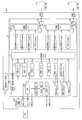
- FIG. 1 showing an embodiment of the present invention, is a block diagram showing a main configuration of a liquid crystal instrument panel system. It is a block diagram which shows the detailed structure of DIC of the liquid crystal platform part with which the liquid crystal instrument panel system shown in FIG. 1 was equipped. It is a figure which shows the example of a display of the instrument panel image displayed on the liquid crystal display part of the liquid crystal instrument panel system shown in FIG. It is a figure for demonstrating two methods of the smooth process in the rotation display of a pointer image.
- an example in which the display system of the present invention is applied to a liquid crystal instrument panel system that is used as an instrument panel (hereinafter referred to as an instrument panel) of a car that is one of steerable moving bodies will be described.
- FIG. 1 is a block diagram showing an outline of a liquid crystal instrument panel system.
- the liquid crystal instrument panel system includes a liquid crystal display unit 100, a liquid crystal platform unit 200, an input stream unit 300, a CPU 400, and a flash writer 500.
- NTSC National Television Standards Committee
- various videos consisting of PAL (Phase Alternating Line) signal and LVDS (Low Voltage Differential Signaling) signal are taken in and combined with the still image inside to create a free layout, LVDS signal or RGB ( An instrument panel image (for example, an image as shown in FIG. 4) composed of a signal of “Red (Green) Blue” system is displayed in real time.
- the liquid crystal display unit 100 includes an LCD panel 101 that displays an image using an LVDS signal and an LCD panel 102 that displays an image using an RGB signal.
- the LCD panel 101 and the LCD panel 102 may be separate panels, or may be configured as a single panel capable of performing LVDS display and RGB display.
- the LCD panel 101 and the LCD panel 102 are not particularly limited to the driving method and the liquid crystal operation mode, and may be a liquid crystal panel of any driving method and liquid crystal operation mode.
- the LCD panel 101 is supplied with an LVDS signal from the liquid crystal platform 200, and the LCD panel 102 is supplied with an RGB signal from the liquid crystal platform 200. Details of the signal generation will be described later.
- the liquid crystal platform 200 includes a DIC (Digital Image Composer) 201, a Flash ROM 202, and a RAM 203.
- DIC Digital Image Composer
- the DIC 201 generates an image to be displayed on the liquid crystal display unit 100 according to an instruction from the CPU 400 from information from the input stream unit 300 and information stored in the RAM 203. Details of image generation in the DIC 201 will be described later.
- the DIC 201 takes in information and outputs an image via various interfaces (I / F) provided in the liquid crystal platform unit 200.
- the liquid crystal platform unit 200 serves as an interface for importing information into the DIC 201, an LVDS I / F for fetching information from the navigation / TV / DVD of the input stream unit 300, and input setting information.
- an LVDS I / F for fetching information from the navigation / TV / DVD of the input stream unit 300, and input setting information.
- NTSC signal or PAL signal from camera, SIBI (Stream Input Bus Bus Interface), and control signal from CPU 400 connected to in-vehicle network
- the 8-bit parallel I / F is provided, and as an interface for outputting information, an LVDS I / F for outputting an LVDS signal (image information) to the LCD panel 101, and an RGB signal (text, RGB I / F is provided to output (image information) To have.
- the RGB I / F on the output side is also used as an input / output.
- the flash ROM 202 (first storage unit) stores a plurality of types of display data having different display condition information of images displayed on the liquid crystal display unit 100. That is, the Flash ROM 202 stores data necessary for displaying each scene in addition to data related to the liquid crystal instrument panel system activation.
- the RAM 203 (second storage unit) is composed of a DDR400 SDRAM, and temporarily stores display data stored in the flash ROM 202.
- Transfer of the display data from the flash ROM 202 to the RAM 203 is controlled by the CPU 400. That is, the CPU 400 controls transfer of display data stored in the flash ROM 202 to the RAM 203 at a predetermined timing.
- the DIC 201 generates an image to be displayed on the liquid crystal display unit 100 from the display data transferred to the RAM 203 instead of the display data stored in the Flash ROM 202.
- the CPU 400 issues a drawing command to the DIC 201, causes the DIC 201 to fetch necessary display data from the RAM 203, and generates an image (instrument panel image) to be displayed on the liquid crystal display unit 100.
- the DIC 201 has four 2D rotation engines (rotation engines) and four animation engines (motion engines), and the pointer display is performed by the rotation engine. Details of these engines will be described later.
- Display data stored in the flash ROM 202 is written by the flash writer 500.
- the display data written by the FlashWriter 500 is created in advance as display data by using a development device composed of a PC (personal computer) as layout and still image information and scene transition table information.
- FIG. 2 is a block diagram showing a detailed configuration of the DIC 201 of the liquid crystal platform unit 200.
- the DIC 201 is centered on the SDRAM interface 211 and is arranged on the data output side to the SDRAM interface 211, and the DDR SDRAM control arranged on the data input side to the SDRAM interface 211.
- the SCAN engine 212 reads the still image data and the contents of the CRAM from the display buffer secured on the RAM 203, reads the pattern data from the RAM 203 and the image data from the moving image buffer, and combines them for display. It has become.
- the SCAN engine 212 also performs processing for copying the contents of the VRAM and CRAM to the display buffer.
- the SCAN engine 212 includes an image composition unit (1) 223, an image composition unit (2) 225 as a frame buffer, a panel (1) TG 224 as an output timing gate, and a panel. (2) TG226. Details of the SCAN engine 212 will be described later.
- the DDR SDRAM control unit 213 controls input / output of display data stored in the RAM 203 based on a control signal sent via the SDRAM interface 211.
- the FMT engine 214 is a program for reading display data from the flash ROM 202 on the basis of a control signal sent via the SDRAM interface 211 and transferring the read display data to the RAM 203.
- the CPU I / F 215 functions as a direct interface between the SDRAM interface 211 and the CPU 400, and functions as an interface with the CPU 400 via the I2C 216.
- the input PORT 217 has a plurality of PORTs for inputting data to the SDRAM interface 211.
- the PORT 1 of the input PORT 217 is assigned an LVDS input
- the PORT 2 is assigned an RGB input
- the PORTs 4 to 7 are assigned NTSC inputs (signals converted from LVDS to NTSC and SIBI inputs)
- the PORT 8 11 to 11 are assigned as PORTs of various signals generated by the ROTATE engine 218, and PORTs 12 to 15 are assigned as PORTs of various signals generated by the MOTION engine 219.
- the ROTATE engine 218 and the MOTION engine 219 perform signal generation processing according to a control signal from the SDRAM interface 211.
- the ROTATE engine 218 and the MOTION engine 219 will be described later.
- SDRAM interface 211 controls the PxBLT engine 220.
- the PxBLT engine 220 is an engine for transferring an image. Specifically, the PxBLT engine 220 is an engine having a function of copying a rectangular area in the two-dimensional space to another area or a function of setting data in a rectangular area in the two-dimensional space. In the present invention, the PxBLT engine 220 is further expanded by adding an enlargement / reduction function and an ⁇ blend function.
- the signal input from the input PORT 217 is output to the SCAN engine 212 via the SDRAM interface 211.
- the SCAN engine 212 outputs signals from the first layer group (SVRAM (1) Layer, MOVIE (1) Layer, CRAM (1) Layer, PG (1) Layer)) for outputting LVDS, and images from the first layer group.
- a panel (2) TG 226 for converting to an output signal and outputting it at a predetermined timing is provided.
- an index to PG (1) Layer and PG (2) Layer is set in advance by the SCAN engine, and image information based on the index is PG (1). It is read from Layer, PG (2) Layer and transferred to the frame buffer by the SCAN engine.
- the image signals generated by the PxBLT engine 220 are input to the SVRAM (1) Layer and the SVRAM (2) Layer, and the MOTION engine 219 and the ROTATE engine 218 are input to the MOVIE (1) Layer and the MOVIE (2) Layer.
- the image signal from various video input ports are input to the CRAM (1) Layer and CRAM (2) Layer in advance by the SCAN engine 212 using the PG (1) Layer and PG (2) Layer.
- the image information based on the index is read from PG (1) Layer and PG (2) Layer, and transferred to the frame buffer by the SCAN engine 212.
- the image composition unit (1) 223 is a frame buffer for developing the signal from the first layer group into an image, and similarly, the image composition unit (2) 225 receives the signal from the second layer group. This is a frame buffer for developing an image.
- the panel (1) TG 224 converts the image developed by the image composition unit (1) 223 into a format (LVDS signal) that can be received by the LCD panel 101, and outputs it at a predetermined timing.
- the panel (2) TG 226 converts the image developed by the image composition unit (2) 225 into a format (RGB signal) that can be received by the LCD panel 102, and at a predetermined timing. It is designed to output.
- a display example of an image displayed on the liquid crystal display unit 100 is shown in FIG.
- a display example of an image displayed on the LCD panel 101 will be described.
- FIG. 3 shows a display example of an instrument panel image of a car.
- the instrument panel image shown in FIG. 3 has a speedometer 111 indicating the traveling speed of the car at the center, a navigation image 112 at the upper left, the tachometer 113 at the lower left, a water thermometer 114 at the lower right, and a right middle.
- the fuel gauge 115 and the respective images showing the engine state 116 in the upper right part are synthesized.
- a pointer image 111a As for the four images of the speedometer 111, the tachometer 113, the water temperature gauge 114, and the fuel gauge 115, a pointer image 111a, a pointer image 113a, a pointer image 114a, and a pointer image 115a are generated by the ROTATE engine 218 shown in FIG.
- the navigation image 112 and the engine state image 116 are changed in display state by the MOTION engine 219 shown in FIG.
- the ROTATE engine 218 is an image generation means for generating an image by affine transformation and anti-aliasing.
- the ROTATE engine 218 generates pointer images at 33 ms intervals for non-interlaced display, and generates pointer images at about 16.7 ms intervals, half of non-interlaced display for interlaced display. become.
- the MOTION engine 219 displays 31 images repeatedly at 60 ms, displays the navigation image 112, displays 105 images repeatedly at 30 ms, and displays I2C 216. It is supposed to be.
- the speedometer 111 is displayed by superimposing the pointer image 111a created in the transparent mode on the background image 111b.
- the pointer image 111a is a display image that is generated as an image such as PNG (Portable Network Graphic) in the ROTATE engine 218 shown in FIG. 2 and rotated by a specified angle about the center point of the background image 111b. .
- PNG Portable Network Graphic
- the speedometer 111 is an analog speedometer, and the center point of the background image 111b is placed on the background image 111b in which speed memories from 0 km / h to 180 km / h are circumferentially engraved. As shown, the pointer image 111a rotated at a specified angle to indicate the current speed is superimposed to display the speed.
- the tachometer 113 is also displayed by superimposing a transparent mode pointer image 113a generated by the ROTATE engine 218 on the background image 113b in the same manner as the speedometer 111 described above.
- the water temperature gauge 114 is also displayed by superimposing a transparent mode pointer image 114a generated by the ROTATE engine 218 on the background image 114b by the same mechanism as the speedometer 111 described above.
- the fuel gauge 115 also displays the transparent mode pointer image 115a generated by the ROTATE engine 218 on the background image 115b by the same mechanism as the speedometer 111 described above.
- the navigation image 112 and the engine state image 116 are animation images in which built-in still images are sequentially drawn at specified time values. These images are generated by the MOTION engine 219 shown in FIG.
- the navigation image 112 and the engine state image 116 are animation images in which built-in still images are sequentially drawn at specified time values, smoothness is not required for image display, but the speedometer generated by the ROTATE engine 218 described above.
- 111 pointer images 111a and the like are required to display images in real time and to be displayed smoothly. This is because if the rotation display of the pointer image 111a is not smooth in the speedometer 111, the driver cannot follow the eye with his eyes, and there is a high possibility of overlooking the speed change. If the speed change is overlooked in this way, there arises a problem that driving cannot be performed safely.
- the pointer image 111a of the speedometer 111 generated by the ROTATE engine 218 is generated at an interval of one frame (33 ms) as described above unless any adjustment is made. Does not necessarily coincide with the timing (acquisition period, transmission interval) for acquiring vehicle information from the vehicle. For this reason, when the generation timing of the pointer image 111a and the timing of acquiring the vehicle information deviate, the display position of the pointer image 111a changes abruptly, and the display of the pointer image 111a is not performed smoothly.
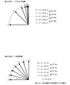
- FIG. 4 is a diagram for explaining two methods of smooth processing in the rotation display of the pointer image.
- G indicates the angular position at the current signal value
- A indicates the angular position at the previous signal value.
- Display method 1 is a method of performing interpolation processing for each half of the angular position at a predetermined time interval in order that the angular position of the pointer image moves from A to G.
- the angular positions B to F are obtained by the equations shown in FIG.
- Each angular position is determined every 16.6 ms. In this case, the display is performed without performing the interpolation process.
- the movement to the G where the angular position of the pointer image is the target angular position is performed quickly and gradually at the beginning.
- the display method 2 is a method of performing interpolation processing at angular positions that are evenly divided at predetermined time intervals in order that the angular position of the pointer image goes from A to G.
- the angular positions B to F are obtained by the equations shown in FIG.
- Z is a value obtained by dividing (GA) by 6 which is the number of interpolations.
- Each angular position is obtained every 20 ms.
- the number of interpolations described above indicates a case where drawing can be performed six times at 20 ms intervals.
- the display is updated so that the movement of the pointer image to G where the angular position of the pointer image is the target angular position is evenly moved.
- the above-described drawing interval of the pointer image is set in accordance with the interval at which the ROTATE engine 218 obtains the information on the angular position, that is, the interval at which the information on the vehicle speed is transmitted in the in-vehicle network, thereby smoothly rotating the pointer image Can do.
- FIG. 5 is a diagram showing the frequency of the vehicle speed interval when 1 ° of the 360 ° angle of the circle in the speedometer 111 is divided into three equal parts.
- the frequency of 0 km / h is 135
- the frequency of 180 km / h is 943
- the calculation frequency corresponding to the speed can be obtained from the calculation formula.
- the calculated frequency obtained here indicates the angular position of the speed meter.
- Calculation frequency (808/180) ⁇ speed + 135
- the calculation of the calculation frequency is performed by the CPU 400 using parameters preset on the development device.
- the CPU 400 creates a ROTATE instruction using the calculated calculation frequency as an argument, and issues it to the ROTATE engine 218 at a predetermined timing.
- the ROTATE engine 218 When receiving the ROTATE command, the ROTATE engine 218 obtains the angular position of the pointer image and outputs it to the SCAN engine 212 via the SDRAM interface 211.
- FIG. 6 is a time chart showing the relationship between the CAN message reception timing and the ROTATE command issue timing.
- the CAN message is information transmitted from the in-vehicle network, and is transmitted at a constant interval (505 ms interval). And it is CPU400 that receives the CAN message transmitted from the vehicle-mounted network.
- the number of times of drawing and the angle of rotation at one time are obtained by the following procedures (1) to (5).
- Difference Angle (T (n)) Angle (T (n))
- ⁇ ( ⁇ 270) 135
- FIG. 7 is a diagram showing a specific example of ROTATE command issuance based on the number of drawing times obtained in FIG. 6 and the rotation angle for each ROTATE command.
- the ROTATE command is issued 25 times until the speed display of 60 km / h is changed to the speed display of 70 km / h, and interpolation processing is performed in the display of the pointer image.
- the CPU 400 issues the ROTATE command at intervals of 20 ms, if the CAN message reception interval is 505 ms, the issuance of the ROTATE command for 5 ms is stopped after 25 ROTATE commands are issued, and the next CAN Waiting for message reception.
- the ROTATE command issuance is maintained in the stopped state.
- the CAN message reception interval obtained in the above (2) is very long. For example, when the CAN message communication is interrupted or the CAN message is missed, until the next CAN message is received. It may be time consuming. Thus, if the CAN message reception interval is very long, the rotation speed of the pointer image becomes slow, and the rotation display of the pointer image is not smooth.
- a maximum value is set for the CAN message reception interval, and if it is determined that the CAN message reception interval is longer than the set maximum value, rotation processing is performed within the maximum value.
- the maximum value of the CAN message reception interval is 1000 ms
- the CAN message reception is not 505 ms later, but 1200 ms later, and the speed is 100 km / h, 700 ms from 500 ms to 1200 ms later Stop.
- the CAN message reception interval exceeds the maximum value of 1000 ms, it is assumed that it has reached 60 km / h to 100 km / h in 1000 ms after reception, and smooth processing is performed between this speed 50 times (1000 ms ⁇ 20 ms). Do.
- FIG. 8 shows an example of a program for issuing the ROTATE instruction shown in FIG.
- the program is not limited to this, and any program that can execute the process shown in FIG. 7 may be used.
- the liquid crystal instrument panel system includes the liquid crystal display unit 100 that is mounted on an automobile and displays information related to the automobile as an image.
- the liquid crystal display unit (image display apparatus) 100 includes the above-described liquid crystal display unit 100.
- LCD panels 101 and 102 image display units
- liquid crystal platform units 200 display data generation for generating images to be displayed on the LCD panels 101 and 102 as display data from information acquired from the automobile.
- a CPU 400 a display position calculation section
- Table of images calculated by the CPU 400 of the LCD panels 101 and 102 DIC 201 is displayed at a position, and when the information acquisition interval from the automobile is longer than the frame interval for image display on the LCD panels 101 and 102, the DIC 201 uses the vehicle information acquired immediately before.
- the image display position calculated by the CPU 400 is set as an image display start position, and the frame interval between the start position and the image display position calculated by the CPU 400 from the information of the automobile acquired at the present time.
- the image display position of the image is updated so as to be moved by.
- the image display from the image display starting position to the current display position is interpolated (interpolated) at the frame interval.
- the human eye can recognize that the display image is moving smoothly.
- the present invention is applied to pointer rotation processing of various rotation meters (mainly speedometers) using the ROTATE engine 218.
- the present invention is applied to various level meters using the MOTION engine 219. It may be applied to the bar display process.
- FIG. 9 is a diagram showing an example in which the increase / decrease state of oil is displayed with a level meter.
- the display process of the level meter is performed by the MOTION engine 219 shown in FIG.
- the MOTION engine 219 is an engine that displays an image specified as a command argument from a plurality of registered still images.
- the plurality of registered still images are 12 still images to which the numbers (number 0 to number 11) shown in FIG. 9 are added.
- still images are buffered in the still image layer.
- the range of the oil value is set as in-vehicle electronic information
- the full tank (F) is set to the maximum value 100
- the sky (E) is set to the minimum value 0
- the number assigned to the still image corresponds to oil. That is, the still image with the number 0 is a level meter image indicating that the oil is the minimum value, and the still image with the number 11 is a level meter image indicating that the oil is the maximum value.
- N 12/100 x oil (value transmitted from in-vehicle network, hereinafter referred to as transmission value) (1)
- N 12 possible values of N, 0, 1, 2, 3, 4, 5, 6, 7, 8, 9, 10, and 11.
- there are twelve or more types of values for example, electrical signals obtained from the oil sensor
- the value actually detected for the oil is between 0L and less than 5L, it is associated with the transmission value indicating the oil whose N is 0 by the above equation (1). Further, if the value actually detected for the oil is between 5L and less than 10L, it is associated with the transmission value indicating the oil for which N is 1 by the above equation (1). In this way, transmission values are associated with all N. This calculation is performed in advance using parameters set according to the vehicle (vehicle type).
- the above-described MOTION engine 219 causes the still image of the corresponding image number from a plurality of still images registered using the obtained N as a command argument. Are buffered in the moving image layer and displayed on the liquid crystal display unit 100.
Abstract
Description
この計算度数の演算は、開発装置上で事前設定されたパラメータにより、CPU400が行う。 Calculation frequency = (808/180) × speed + 135
The calculation of the calculation frequency is performed by the
(2)CANメッセージ受信時間間隔T(CAN(n))=T(n)-T(n-1)=605-100=505ms
(3)差分Angle(T(n))=Angle(T(n))-Angle(T(n-1))=60km/hのAngle-30km/hnoAngle=(-135)-(-270)=135
(4)ROTATE命令発行可能回数(T(n))=上記の(2)/上記の(1)=505/20=25・・・・505msの間に25回描画できることを示す。 (1) ROTATE instruction issue time interval T (ROT) = # define value = 20 ms
(2) CAN message reception time interval T (CAN (n)) = T (n) −T (n−1) = 605-100 = 505 ms
(3) Difference Angle (T (n)) = Angle (T (n)) − Angle (T (n−1)) = Angle of 60 km / h−30 km / hnoAngle = (− 135) − (− 270) = 135
(4) Rotate command issuable number of times (T (n)) = (2) / (1) = 505/20 = 25... 505 ms can be drawn 25 times in 505 ms.
上記Nがとり得る値は、0,1,2,3,4,5,6,7,8,9,10,11の12種類である。一方、油糧を直接検出した値(例えば、油糧センサから得られる電気信号)は12種類以上存在する。そこで、油糧を示す値を、実際に検出される値から、予め設定されたパラメータで12種類になるように計算しておく必要がある。例えば、満タン時の油糧が60Lである場合、60Lを5Lずつ均等に分けて12種類の範囲(0L~5L未満、5L~10L未満、10L~15L未満、・・・・50L~55L未満、55L~60L)とする。そして、油糧を実際に検出した値が0L~5L未満の間を示す値であれば、上記式(1)によってNが0となるような油糧を示す送信値に対応付ける。また、油糧を実際に検出した値が5L~10L未満の間を示す値であれば、上記式(1)によってNが1となるような油糧を示す送信値に対応付ける。このようにして全てのNに対して送信値を対応付ける。この演算は、車両(車種)に応じて設定されるパラメータを用いて予め行っておく。 N = 12/100 x oil (value transmitted from in-vehicle network, hereinafter referred to as transmission value) (1)
There are 12 possible values of N, 0, 1, 2, 3, 4, 5, 6, 7, 8, 9, 10, and 11. On the other hand, there are twelve or more types of values (for example, electrical signals obtained from the oil sensor) that directly detect the oil. Therefore, it is necessary to calculate the values indicating the oil supply from the actually detected values so that there are 12 types with preset parameters. For example, when oil is 60L when full, 60L is divided equally by 5L and 12 ranges (0L to less than 5L, 5L to less than 10L, 10L to less than 15L, ... 50L to less than 55L , 55L-60L). If the value actually detected for the oil is between 0L and less than 5L, it is associated with the transmission value indicating the oil whose N is 0 by the above equation (1). Further, if the value actually detected for the oil is between 5L and less than 10L, it is associated with the transmission value indicating the oil for which N is 1 by the above equation (1). In this way, transmission values are associated with all N. This calculation is performed in advance using parameters set according to the vehicle (vehicle type).
Claims (26)
- 操縦可能な移動体に搭載され、上記移動体に関する情報を画像として表示する画像表示装置を備えた表示システムにおいて、
上記画像表示装置は、
上記画像を表示する画像表示部と、
上記移動体から取得した情報から上記画像表示部に表示すべき画像を表示用データとして生成する表示用データ生成部と、
上記移動体から取得した情報から上記画像表示部に表示する画像の表示位置を算出する表示位置算出部と、
上記表示用データ生成部により生成された表示用データを、上記画像表示部の、上記表示位置算出部により算出された画像の表示位置に表示させる表示制御部とを備え、
上記表示制御部は、
上記移動体からの情報の取得間隔が、上記画像表示部における画像表示のためのフレーム間隔よりも長い場合、
直前に取得した移動体の情報から上記表示位置算出部によって算出された画像表示位置を画像表示の起点位置として、上記起点位置から、現時点で取得した移動体の情報から上記表示位置算出部によって算出された画像表示位置までの間を、上記画像が上記フレーム間隔で移動するように該画像の画像表示位置の更新を行うことを特徴とする表示システム。 In a display system equipped with an image display device that is mounted on a steerable mobile body and displays information about the mobile body as an image,
The image display device
An image display unit for displaying the image;
A display data generation unit that generates, as display data, an image to be displayed on the image display unit from information acquired from the mobile body;
A display position calculation unit for calculating a display position of an image to be displayed on the image display unit from information acquired from the mobile body;
A display control unit for displaying the display data generated by the display data generation unit at the display position of the image calculated by the display position calculation unit of the image display unit;
The display control unit
When the acquisition interval of information from the moving body is longer than the frame interval for image display in the image display unit,
The image display position calculated by the display position calculation unit from the information of the mobile body acquired immediately before is used as the starting position of the image display, and the display position calculation unit is calculated from the information of the mobile body acquired at the present time from the start position. A display system, wherein the image display position of the image is updated so that the image moves at the frame interval between the displayed image display positions. - 上記表示制御部は、
上記起点位置から、現時点で取得した移動体の情報から上記表示位置算出部によって算出された画像表示位置までの間を移動する画像の移動間隔が等間隔となるように画像表示位置の更新を行うことを特徴とする請求項1に記載の表示システム。 The display control unit
The image display position is updated so that the moving interval of the image moving from the starting position to the image display position calculated by the display position calculation unit from the information of the moving body acquired at the present time becomes equal. The display system according to claim 1. - 上記画像表示部に表示すべき画像は、移動体自身の移動速度を示す画像であることを特徴とする請求項1または2に記載の表示システム。 The display system according to claim 1 or 2, wherein the image to be displayed on the image display unit is an image indicating a moving speed of the moving body itself.
- 上記画像は、回転計の指針を示す画像であることを特徴とする請求項3に記載の表示システム。 4. The display system according to claim 3, wherein the image is an image showing a pointer of a tachometer.
- 上記画像は、レベルメータのレベル変化を表す複数の静止画像であることを特徴とする請求項3に記載の表示システム。 4. The display system according to claim 3, wherein the image is a plurality of still images representing a level change of a level meter.
- 上記画像表示装置は、液晶表示装置であることを特徴とする請求項1~5の何れか1項に記載の表示システム。 The display system according to any one of claims 1 to 5, wherein the image display device is a liquid crystal display device.
- 上記移動体は、車両であることを特徴とする請求項1~6の何れか1項に記載の表示システム。 The display system according to any one of claims 1 to 6, wherein the moving body is a vehicle.
- 操縦可能な移動体に搭載され、上記移動体から取得した情報から画像の表示位置を算出し、算出した表示位置に画像を表示する画像表示装置において、
上記画像を表示する画像表示部と、
上記移動体から取得した情報から上記画像表示部に表示すべき画像を表示用データとして生成する表示用データ生成部と、
上記移動体から取得した情報から上記画像表示部に表示する画像の表示位置を算出する表示位置算出部と、
上記表示用データ生成部により生成された表示用データを、上記画像表示部の、上記表示位置算出部により算出された画像の表示位置に表示させる表示制御部とを備え、
上記表示制御部は、
上記移動体からの情報の取得間隔が、上記画像表示部における画像表示のためのフレーム間隔よりも長い場合、
直前に取得した移動体の情報から上記表示位置算出部によって算出された画像表示位置を画像表示の起点位置として、上記起点位置から、現時点で取得した移動体の情報から上記表示位置算出部によって算出された画像表示位置までの間を、上記画像が上記フレーム間隔で移動するように該画像の画像表示位置の更新を行うことを特徴とする画像表示装置。 In an image display device that is mounted on a steerable mobile body, calculates a display position of an image from information acquired from the mobile body, and displays an image at the calculated display position.
An image display unit for displaying the image;
A display data generation unit that generates, as display data, an image to be displayed on the image display unit from information acquired from the mobile body;
A display position calculation unit for calculating a display position of an image to be displayed on the image display unit from information acquired from the mobile body;
A display control unit for displaying the display data generated by the display data generation unit at the display position of the image calculated by the display position calculation unit of the image display unit;
The display control unit
When the acquisition interval of information from the moving body is longer than the frame interval for image display in the image display unit,
The image display position calculated by the display position calculation unit from the information of the mobile body acquired immediately before is used as the starting position of the image display, and the display position calculation unit is calculated from the information of the mobile body acquired at the present time from the start position. An image display device, wherein the image display position of the image is updated so that the image moves at the frame interval between the displayed image display positions. - 上記表示制御部は、
上記起点位置から、現時点で取得した移動体の情報から上記表示位置算出部によって算出された画像表示位置までの間を移動する画像の移動間隔が等間隔となるように画像表示位置の更新を行うことを特徴とする請求項8に記載の画像表示装置。 The display control unit
The image display position is updated so that the moving interval of the image moving from the starting position to the image display position calculated by the display position calculation unit from the information of the moving body acquired at the present time becomes equal. The image display device according to claim 8. - 上記画像表示部に表示すべき画像は、移動体自身の移動速度を示す画像であることを特徴とする請求項8または9に記載の画像表示装置。 10. The image display device according to claim 8, wherein the image to be displayed on the image display unit is an image indicating a moving speed of the moving body itself.
- 上記画像は、回転計の指針を示す画像であることを特徴とする請求項10に記載の画像表示装置。 The image display device according to claim 10, wherein the image is an image showing a pointer of a tachometer.
- 上記画像は、レベルメータのレベル変化を表す複数の静止画像であることを特徴とする請求項10に記載の画像表示装置。 11. The image display device according to claim 10, wherein the image is a plurality of still images representing a level change of a level meter.
- 上記画像表示装置は、液晶表示装置であることを特徴とする請求項8~12の何れか1項に記載の画像表示装置。 The image display device according to any one of claims 8 to 12, wherein the image display device is a liquid crystal display device.
- 上記移動体は、車両であることを特徴とする請求項8~13の何れか1項に記載の画像表示装置。 14. The image display device according to claim 8, wherein the moving body is a vehicle.
- 操縦可能な移動体に接続され、該移動体から取得した情報からえら得た画像表示位置に、表示すべき画像を表示する画像表示装置の表示制御装置において、
上記移動体からの情報の取得間隔が、上記画像表示装置における画像表示のためのフレーム間隔よりも長い場合、
直前に取得した移動体の情報から算出された画像表示位置を画像表示の起点位置として、上記起点位置から、現時点で取得した移動体の情報から算出された画像表示位置までの間を、上記画像が上記フレーム間隔で移動するように該画像の画像表示位置の更新を行うことを特徴とする表示制御装置。 In a display control device of an image display device that is connected to a steerable mobile body and displays an image to be displayed at an image display position obtained from information acquired from the mobile body,
When the acquisition interval of information from the moving body is longer than the frame interval for image display in the image display device,
The image display position calculated from the information of the moving body acquired immediately before is used as the starting position of the image display, and the image display position is calculated from the starting position to the image display position calculated from the information of the moving body acquired at the present time. A display control apparatus that updates an image display position of the image so that the image moves at the frame interval. - 上記起点位置から、現時点で取得した移動体の情報から算出された画像表示位置までの間を移動する画像の移動間隔が等間隔となるように画像表示位置の更新を行うことを特徴とする請求項15に記載の表示制御装置。 The image display position is updated such that the movement interval of the image moving from the starting position to the image display position calculated from the information of the moving body acquired at the present time is equal. Item 16. The display control device according to Item 15.
- 上記画像表示装置に表示すべき画像は、移動体自身の移動速度を示す画像であることを特徴とする請求項15または16に記載の表示制御装置。 The display control device according to claim 15 or 16, wherein the image to be displayed on the image display device is an image indicating a moving speed of the moving body itself.
- 上記画像は、回転計の指針を示す画像であることを特徴とする請求項17に記載の表示制御装置。 18. The display control apparatus according to claim 17, wherein the image is an image showing a pointer of a tachometer.
- 上記画像は、レベルメータのレベル変化を表す複数の静止画像であることを特徴とする請求項17に記載の表示制御装置。 The display control apparatus according to claim 17, wherein the image is a plurality of still images representing a level change of a level meter.
- 上記画像表示装置は、液晶表示装置であることを特徴とする請求項15~19の何れか1項に記載の表示制御装置。 The display control device according to any one of claims 15 to 19, wherein the image display device is a liquid crystal display device.
- 上記移動体は、車両であることを特徴とする請求項15~20の何れか1項に記載の表示制御装置。 The display control device according to any one of claims 15 to 20, wherein the moving body is a vehicle.
- 時間によって表示位置が変化する画像を表示する画像表示装置であって、取得した表示位置に関する情報から画像の表示位置を算出し、算出した表示位置に画像を表示する画像表示装置において、
上記画像を表示する画像表示部と、
取得した情報から上記画像表示部に表示すべき画像を表示用データとして生成する表示用データ生成部と、
上記取得した情報から上記画像表示部に表示する画像の表示位置を算出する表示位置算出部と、
上記表示用データ生成部により生成された表示用データを、上記画像表示部の、上記表示位置算出部により算出された画像の表示位置に表示させる表示制御部とを備え、
上記表示制御部は、
上記情報の取得間隔が、上記画像表示部における画像表示のためのフレーム間隔よりも長い場合、
直前に取得した情報から上記表示位置算出部によって算出された画像表示位置を画像表示の起点位置として、上記起点位置から、現時点で取得した情報から上記表示位置算出部によって算出された画像表示位置までの間を、上記画像が上記フレーム間隔で移動するように該画像の画像表示位置の更新を行うことを特徴とする画像表示装置。 In an image display device that displays an image whose display position changes with time, the image display position is calculated from information about the acquired display position, and the image is displayed at the calculated display position.
An image display unit for displaying the image;
A display data generation unit that generates, as display data, an image to be displayed on the image display unit from the acquired information;
A display position calculation unit that calculates a display position of an image to be displayed on the image display unit from the acquired information;
A display control unit for displaying the display data generated by the display data generation unit at the display position of the image calculated by the display position calculation unit of the image display unit;
The display control unit
When the acquisition interval of the information is longer than the frame interval for image display in the image display unit,
Using the image display position calculated by the display position calculation unit from the information acquired immediately before as the image display start position, from the start position to the image display position calculated by the display position calculation unit from the information acquired at the present time An image display device that updates an image display position of the image so that the image moves between the frames at the frame intervals. - 上記表示制御部は、
上記起点位置から、現時点で取得した情報から上記表示位置算出部によって算出された画像表示位置までの間を移動する画像の移動間隔が等間隔となるように画像表示位置の更新を行うことを特徴とする請求項22に記載の画像表示装置。 The display control unit
The image display position is updated so that the movement interval of the image moving from the starting position to the image display position calculated by the display position calculation unit from the information acquired at the present time is equal. The image display device according to claim 22. - 上記画像は、回転計の指針を示す画像であることを特徴とする請求項22または23に記載の画像表示装置。 The image display device according to claim 22 or 23, wherein the image is an image showing a pointer of a tachometer.
- 上記画像は、レベルメータのレベル変化を表す複数の静止画像であることを特徴とする請求項22または23に記載の画像表示装置。 The image display device according to claim 22 or 23, wherein the image is a plurality of still images representing a level change of a level meter.
- 上記画像表示装置は、液晶表示装置であることを特徴とする請求項22~25の何れか1項に記載の画像表示装置。 The image display device according to any one of claims 22 to 25, wherein the image display device is a liquid crystal display device.
Priority Applications (4)
| Application Number | Priority Date | Filing Date | Title |
|---|---|---|---|
| JP2009550426A JP5000728B2 (en) | 2008-01-22 | 2008-11-14 | Display system, display control device, image display device |
| US12/810,910 US8339255B2 (en) | 2008-01-22 | 2008-11-14 | Display system, display control device and image display device |
| EP08871442A EP2241861A4 (en) | 2008-01-22 | 2008-11-14 | Display system, display control device, image display device |
| CN200880124643XA CN101932915B (en) | 2008-01-22 | 2008-11-14 | Display system, display control device, image display device |
Applications Claiming Priority (2)
| Application Number | Priority Date | Filing Date | Title |
|---|---|---|---|
| JP2008012034 | 2008-01-22 | ||
| JP2008-012034 | 2008-01-22 |
Publications (1)
| Publication Number | Publication Date |
|---|---|
| WO2009093371A1 true WO2009093371A1 (en) | 2009-07-30 |
Family
ID=40900887
Family Applications (1)
| Application Number | Title | Priority Date | Filing Date |
|---|---|---|---|
| PCT/JP2008/070771 WO2009093371A1 (en) | 2008-01-22 | 2008-11-14 | Display system, display control device, image display device |
Country Status (5)
| Country | Link |
|---|---|
| US (1) | US8339255B2 (en) |
| EP (1) | EP2241861A4 (en) |
| JP (1) | JP5000728B2 (en) |
| CN (1) | CN101932915B (en) |
| WO (1) | WO2009093371A1 (en) |
Cited By (4)
| Publication number | Priority date | Publication date | Assignee | Title |
|---|---|---|---|---|
| JP2013032950A (en) * | 2011-08-01 | 2013-02-14 | Denso Corp | Display device |
| EP2584556A1 (en) * | 2010-06-16 | 2013-04-24 | Yazaki Corporation | Image display device |
| JP2013161322A (en) * | 2012-02-07 | 2013-08-19 | Mitsubishi Electric Corp | Panel display device and panel display method |
| JP2017045214A (en) * | 2015-08-26 | 2017-03-02 | 三菱電機株式会社 | Gui creating device and gui creating method |
Families Citing this family (11)
| Publication number | Priority date | Publication date | Assignee | Title |
|---|---|---|---|---|
| JP5375893B2 (en) * | 2011-08-10 | 2013-12-25 | カシオ計算機株式会社 | Nail design display control apparatus and display control method |
| CN103714787A (en) * | 2012-09-28 | 2014-04-09 | 比亚迪股份有限公司 | Liquid crystal instrument display method and automobile liquid crystal display device |
| DE102012219924A1 (en) * | 2012-10-31 | 2014-04-30 | Bayerische Motoren Werke Aktiengesellschaft | Vehicle assistance device |
| CN102946527A (en) * | 2012-11-26 | 2013-02-27 | 成都爱斯顿测控技术有限公司 | Multiple input video processing card |
| WO2014203888A1 (en) * | 2013-06-21 | 2014-12-24 | 矢崎総業株式会社 | Display device |
| JP5926332B2 (en) | 2014-07-31 | 2016-05-25 | 本田技研工業株式会社 | Meter display device for vehicle |
| KR101942793B1 (en) * | 2015-07-03 | 2019-01-28 | 엘지전자 주식회사 | Driver Assistance Apparatus and Vehicle Having The Same |
| DE102015224943A1 (en) * | 2015-12-11 | 2017-06-14 | Bayerische Motoren Werke Aktiengesellschaft | Device for displaying indications in motor vehicles |
| CN106314153A (en) * | 2016-08-14 | 2017-01-11 | 蓝聪科技(上海)有限公司 | Virtual instrument system and virtual instrument display method |
| CN107415954A (en) * | 2017-07-24 | 2017-12-01 | 大陆汽车车身电子系统(芜湖)有限公司 | The method and instrument of car speed are shown under cruise pattern |
| CN111890928B (en) * | 2020-07-16 | 2023-09-15 | 无锡华普微电子有限公司 | Automobile liquid crystal instrument pointer control method |
Citations (5)
| Publication number | Priority date | Publication date | Assignee | Title |
|---|---|---|---|---|
| JP2005345780A (en) * | 2004-06-03 | 2005-12-15 | Denso Corp | Liquid crystal display |
| WO2006022191A1 (en) | 2004-08-24 | 2006-03-02 | Sharp Kabushiki Kaisha | Display system |
| JP2006234505A (en) | 2005-02-23 | 2006-09-07 | Denso Corp | Instrument and pointer display method for instrument |
| JP2007178179A (en) * | 2005-12-27 | 2007-07-12 | Yazaki Corp | Liquid crystal display meter |
| JP2008189211A (en) * | 2007-02-07 | 2008-08-21 | Nippon Seiki Co Ltd | Vehicular display device |
Family Cites Families (17)
| Publication number | Priority date | Publication date | Assignee | Title |
|---|---|---|---|---|
| JPH09123848A (en) | 1995-11-06 | 1997-05-13 | Toyota Motor Corp | Vehicular information display device |
| US6463363B1 (en) * | 1999-03-19 | 2002-10-08 | Yazaki Corporation | Back monitoring apparatus for vehicle |
| EP1050866B1 (en) * | 1999-04-28 | 2003-07-09 | Matsushita Electric Industrial Co., Ltd. | Parking assistance device and method |
| JP2000324451A (en) | 1999-05-14 | 2000-11-24 | Sony Corp | Method and device for reproducing video data and video sending system |
| JP2001117074A (en) * | 1999-10-18 | 2001-04-27 | Hitachi Ltd | Liquid crystal display device |
| JP2005088673A (en) | 2003-09-16 | 2005-04-07 | Denso Corp | Vehicular meter with display, and method and device for providing image displayed on the display |
| DE602004022865D1 (en) * | 2003-12-01 | 2009-10-08 | Koninkl Philips Electronics Nv | MOTION-COMPENSATED INVERSE FILTRATION WITH BELT PASS FILTERS FOR MOTORIZED POLLUTION REDUCTION |
| US20070139355A1 (en) * | 2004-02-17 | 2007-06-21 | Sharp Kabushiki Kaisha | Display device and automobile having the same |
| DE102004014672A1 (en) * | 2004-03-25 | 2005-10-13 | Robert Bosch Gmbh | Display unit for displaying safety data in a vehicle comprises a liquid crystal display, an image data source and a temperature measuring unit for determining a display temperature |
| US7321294B2 (en) * | 2004-04-21 | 2008-01-22 | Sharp Kabushiki Kaisha | Display device, instrument panel, automotive vehicle and method for controlling instrument panel |
| CN101668149B (en) * | 2004-08-10 | 2013-02-27 | 索尼株式会社 | Image processing apparatus, image processing method and image display system |
| JP4446168B2 (en) | 2004-11-25 | 2010-04-07 | 株式会社デンソー | Automotive control device |
| JP2006293901A (en) | 2005-04-14 | 2006-10-26 | Fujitsu Ten Ltd | Onboard system and onboard terminal |
| JP2007041196A (en) * | 2005-08-02 | 2007-02-15 | Sony Corp | Device and method for processing image, and computer program |
| JP4726614B2 (en) | 2005-11-25 | 2011-07-20 | シャープ株式会社 | Portable information terminal |
| US7843462B2 (en) * | 2007-09-07 | 2010-11-30 | Seiko Epson Corporation | System and method for displaying a digital video sequence modified to compensate for perceived blur |
| JP2009116043A (en) | 2007-11-06 | 2009-05-28 | Sharp Corp | Display system, data output device for display, display control device, display control method, display control program and computer readable recording medium |
-
2008
- 2008-11-14 US US12/810,910 patent/US8339255B2/en active Active
- 2008-11-14 JP JP2009550426A patent/JP5000728B2/en not_active Expired - Fee Related
- 2008-11-14 WO PCT/JP2008/070771 patent/WO2009093371A1/en active Application Filing
- 2008-11-14 EP EP08871442A patent/EP2241861A4/en not_active Withdrawn
- 2008-11-14 CN CN200880124643XA patent/CN101932915B/en active Active
Patent Citations (5)
| Publication number | Priority date | Publication date | Assignee | Title |
|---|---|---|---|---|
| JP2005345780A (en) * | 2004-06-03 | 2005-12-15 | Denso Corp | Liquid crystal display |
| WO2006022191A1 (en) | 2004-08-24 | 2006-03-02 | Sharp Kabushiki Kaisha | Display system |
| JP2006234505A (en) | 2005-02-23 | 2006-09-07 | Denso Corp | Instrument and pointer display method for instrument |
| JP2007178179A (en) * | 2005-12-27 | 2007-07-12 | Yazaki Corp | Liquid crystal display meter |
| JP2008189211A (en) * | 2007-02-07 | 2008-08-21 | Nippon Seiki Co Ltd | Vehicular display device |
Non-Patent Citations (1)
| Title |
|---|
| See also references of EP2241861A4 |
Cited By (6)
| Publication number | Priority date | Publication date | Assignee | Title |
|---|---|---|---|---|
| EP2584556A1 (en) * | 2010-06-16 | 2013-04-24 | Yazaki Corporation | Image display device |
| EP2584556A4 (en) * | 2010-06-16 | 2014-01-08 | Yazaki Corp | Image display device |
| US9367513B2 (en) | 2010-06-16 | 2016-06-14 | Yazaki Corporation | Image display device |
| JP2013032950A (en) * | 2011-08-01 | 2013-02-14 | Denso Corp | Display device |
| JP2013161322A (en) * | 2012-02-07 | 2013-08-19 | Mitsubishi Electric Corp | Panel display device and panel display method |
| JP2017045214A (en) * | 2015-08-26 | 2017-03-02 | 三菱電機株式会社 | Gui creating device and gui creating method |
Also Published As
| Publication number | Publication date |
|---|---|
| JPWO2009093371A1 (en) | 2011-05-26 |
| US8339255B2 (en) | 2012-12-25 |
| JP5000728B2 (en) | 2012-08-15 |
| EP2241861A4 (en) | 2013-02-27 |
| CN101932915A (en) | 2010-12-29 |
| CN101932915B (en) | 2012-06-27 |
| EP2241861A1 (en) | 2010-10-20 |
| US20100283597A1 (en) | 2010-11-11 |
Similar Documents
| Publication | Publication Date | Title |
|---|---|---|
| JP5000728B2 (en) | Display system, display control device, image display device | |
| US7965177B2 (en) | Display system, screen design setting tool, display system program, screen design setting program, and recording medium | |
| US9493106B2 (en) | Image displaying speedometer | |
| JP6621998B2 (en) | Vehicle display device | |
| JP2007153116A (en) | Vehicle instrument indication device and vehicle instrument display method | |
| JP2010030331A (en) | Vehicle display device | |
| JP2012086691A (en) | Display device for vehicle | |
| JP5185642B2 (en) | Vehicle display device | |
| WO2015011807A1 (en) | Display system, method, and program | |
| JP6181949B2 (en) | Display device | |
| US9770948B2 (en) | Display device | |
| JP5187574B2 (en) | Vehicle display device | |
| JP2010228472A (en) | Display device for vehicle | |
| JP4967953B2 (en) | Meter unit for vehicles | |
| JP2014032071A (en) | Vehicular display device | |
| JP6285656B2 (en) | Display device | |
| JP5210973B2 (en) | Automotive instrument and display method for automotive instrument | |
| JP2018205625A (en) | Display control device, display system and display control method | |
| JP6278655B2 (en) | Graphic meter | |
| JP6118126B2 (en) | Vehicle display device | |
| JP4711001B2 (en) | Vehicle instrument and method of displaying vehicle state value | |
| JP6733182B2 (en) | Vehicle display device and display panel control method | |
| JP2014221630A (en) | Display device | |
| JP6603761B2 (en) | Vehicle display device | |
| JP5622023B2 (en) | Vehicle display device |
Legal Events
| Date | Code | Title | Description |
|---|---|---|---|
| WWE | Wipo information: entry into national phase |
Ref document number: 200880124643.X Country of ref document: CN |
|
| 121 | Ep: the epo has been informed by wipo that ep was designated in this application |
Ref document number: 08871442 Country of ref document: EP Kind code of ref document: A1 |
|
| WWE | Wipo information: entry into national phase |
Ref document number: 2009550426 Country of ref document: JP |
|
| WWE | Wipo information: entry into national phase |
Ref document number: 12810910 Country of ref document: US |
|
| WWE | Wipo information: entry into national phase |
Ref document number: 2008871442 Country of ref document: EP |
|
| NENP | Non-entry into the national phase |
Ref country code: DE |