WO2009084641A1 - Screw compressor - Google Patents
Screw compressor Download PDFInfo
- Publication number
- WO2009084641A1 WO2009084641A1 PCT/JP2008/073759 JP2008073759W WO2009084641A1 WO 2009084641 A1 WO2009084641 A1 WO 2009084641A1 JP 2008073759 W JP2008073759 W JP 2008073759W WO 2009084641 A1 WO2009084641 A1 WO 2009084641A1
- Authority
- WO
- WIPO (PCT)
- Prior art keywords
- rotor
- screw
- gate rotor
- seal
- screw compressor
- Prior art date
Links
Images


Classifications
-
- F—MECHANICAL ENGINEERING; LIGHTING; HEATING; WEAPONS; BLASTING
- F04—POSITIVE - DISPLACEMENT MACHINES FOR LIQUIDS; PUMPS FOR LIQUIDS OR ELASTIC FLUIDS
- F04C—ROTARY-PISTON, OR OSCILLATING-PISTON, POSITIVE-DISPLACEMENT MACHINES FOR LIQUIDS; ROTARY-PISTON, OR OSCILLATING-PISTON, POSITIVE-DISPLACEMENT PUMPS
- F04C18/00—Rotary-piston pumps specially adapted for elastic fluids
- F04C18/48—Rotary-piston pumps with non-parallel axes of movement of co-operating members
- F04C18/50—Rotary-piston pumps with non-parallel axes of movement of co-operating members the axes being arranged at an angle of 90 degrees
- F04C18/52—Rotary-piston pumps with non-parallel axes of movement of co-operating members the axes being arranged at an angle of 90 degrees of intermeshing engagement type, i.e. with engagement of co-operating members similar to that of toothed gearing
-
- F—MECHANICAL ENGINEERING; LIGHTING; HEATING; WEAPONS; BLASTING
- F01—MACHINES OR ENGINES IN GENERAL; ENGINE PLANTS IN GENERAL; STEAM ENGINES
- F01C—ROTARY-PISTON OR OSCILLATING-PISTON MACHINES OR ENGINES
- F01C17/00—Arrangements for drive of co-operating members, e.g. for rotary piston and casing
- F01C17/02—Arrangements for drive of co-operating members, e.g. for rotary piston and casing of toothed-gearing type
-
- F—MECHANICAL ENGINEERING; LIGHTING; HEATING; WEAPONS; BLASTING
- F04—POSITIVE - DISPLACEMENT MACHINES FOR LIQUIDS; PUMPS FOR LIQUIDS OR ELASTIC FLUIDS
- F04C—ROTARY-PISTON, OR OSCILLATING-PISTON, POSITIVE-DISPLACEMENT MACHINES FOR LIQUIDS; ROTARY-PISTON, OR OSCILLATING-PISTON, POSITIVE-DISPLACEMENT PUMPS
- F04C23/00—Combinations of two or more pumps, each being of rotary-piston or oscillating-piston type, specially adapted for elastic fluids; Pumping installations specially adapted for elastic fluids; Multi-stage pumps specially adapted for elastic fluids
- F04C23/001—Combinations of two or more pumps, each being of rotary-piston or oscillating-piston type, specially adapted for elastic fluids; Pumping installations specially adapted for elastic fluids; Multi-stage pumps specially adapted for elastic fluids of similar working principle
-
- F—MECHANICAL ENGINEERING; LIGHTING; HEATING; WEAPONS; BLASTING
- F04—POSITIVE - DISPLACEMENT MACHINES FOR LIQUIDS; PUMPS FOR LIQUIDS OR ELASTIC FLUIDS
- F04C—ROTARY-PISTON, OR OSCILLATING-PISTON, POSITIVE-DISPLACEMENT MACHINES FOR LIQUIDS; ROTARY-PISTON, OR OSCILLATING-PISTON, POSITIVE-DISPLACEMENT PUMPS
- F04C27/00—Sealing arrangements in rotary-piston pumps specially adapted for elastic fluids
- F04C27/001—Radial sealings for working fluid
- F04C27/004—Radial sealing elements specially adapted for intermeshing-engagement type pumps, e.g. gear pumps
-
- F—MECHANICAL ENGINEERING; LIGHTING; HEATING; WEAPONS; BLASTING
- F04—POSITIVE - DISPLACEMENT MACHINES FOR LIQUIDS; PUMPS FOR LIQUIDS OR ELASTIC FLUIDS
- F04C—ROTARY-PISTON, OR OSCILLATING-PISTON, POSITIVE-DISPLACEMENT MACHINES FOR LIQUIDS; ROTARY-PISTON, OR OSCILLATING-PISTON, POSITIVE-DISPLACEMENT PUMPS
- F04C29/00—Component parts, details or accessories of pumps or pumping installations, not provided for in groups F04C18/00 - F04C28/00
- F04C29/0042—Driving elements, brakes, couplings, transmissions specially adapted for pumps
- F04C29/0078—Fixing rotors on shafts, e.g. by clamping together hub and shaft
-
- F—MECHANICAL ENGINEERING; LIGHTING; HEATING; WEAPONS; BLASTING
- F04—POSITIVE - DISPLACEMENT MACHINES FOR LIQUIDS; PUMPS FOR LIQUIDS OR ELASTIC FLUIDS
- F04C—ROTARY-PISTON, OR OSCILLATING-PISTON, POSITIVE-DISPLACEMENT MACHINES FOR LIQUIDS; ROTARY-PISTON, OR OSCILLATING-PISTON, POSITIVE-DISPLACEMENT PUMPS
- F04C29/00—Component parts, details or accessories of pumps or pumping installations, not provided for in groups F04C18/00 - F04C28/00
- F04C29/12—Arrangements for admission or discharge of the working fluid, e.g. constructional features of the inlet or outlet
- F04C29/124—Arrangements for admission or discharge of the working fluid, e.g. constructional features of the inlet or outlet with inlet and outlet valves specially adapted for rotary or oscillating piston pumps
-
- F—MECHANICAL ENGINEERING; LIGHTING; HEATING; WEAPONS; BLASTING
- F04—POSITIVE - DISPLACEMENT MACHINES FOR LIQUIDS; PUMPS FOR LIQUIDS OR ELASTIC FLUIDS
- F04C—ROTARY-PISTON, OR OSCILLATING-PISTON, POSITIVE-DISPLACEMENT MACHINES FOR LIQUIDS; ROTARY-PISTON, OR OSCILLATING-PISTON, POSITIVE-DISPLACEMENT PUMPS
- F04C18/00—Rotary-piston pumps specially adapted for elastic fluids
- F04C18/08—Rotary-piston pumps specially adapted for elastic fluids of intermeshing-engagement type, i.e. with engagement of co-operating members similar to that of toothed gearing
- F04C18/12—Rotary-piston pumps specially adapted for elastic fluids of intermeshing-engagement type, i.e. with engagement of co-operating members similar to that of toothed gearing of other than internal-axis type
- F04C18/14—Rotary-piston pumps specially adapted for elastic fluids of intermeshing-engagement type, i.e. with engagement of co-operating members similar to that of toothed gearing of other than internal-axis type with toothed rotary pistons
- F04C18/16—Rotary-piston pumps specially adapted for elastic fluids of intermeshing-engagement type, i.e. with engagement of co-operating members similar to that of toothed gearing of other than internal-axis type with toothed rotary pistons with helical teeth, e.g. chevron-shaped, screw type
-
- F—MECHANICAL ENGINEERING; LIGHTING; HEATING; WEAPONS; BLASTING
- F04—POSITIVE - DISPLACEMENT MACHINES FOR LIQUIDS; PUMPS FOR LIQUIDS OR ELASTIC FLUIDS
- F04C—ROTARY-PISTON, OR OSCILLATING-PISTON, POSITIVE-DISPLACEMENT MACHINES FOR LIQUIDS; ROTARY-PISTON, OR OSCILLATING-PISTON, POSITIVE-DISPLACEMENT PUMPS
- F04C2240/00—Components
- F04C2240/30—Casings or housings
-
- F—MECHANICAL ENGINEERING; LIGHTING; HEATING; WEAPONS; BLASTING
- F04—POSITIVE - DISPLACEMENT MACHINES FOR LIQUIDS; PUMPS FOR LIQUIDS OR ELASTIC FLUIDS
- F04C—ROTARY-PISTON, OR OSCILLATING-PISTON, POSITIVE-DISPLACEMENT MACHINES FOR LIQUIDS; ROTARY-PISTON, OR OSCILLATING-PISTON, POSITIVE-DISPLACEMENT PUMPS
- F04C2240/00—Components
- F04C2240/50—Bearings
- F04C2240/52—Bearings for assemblies with supports on both sides
-
- F—MECHANICAL ENGINEERING; LIGHTING; HEATING; WEAPONS; BLASTING
- F04—POSITIVE - DISPLACEMENT MACHINES FOR LIQUIDS; PUMPS FOR LIQUIDS OR ELASTIC FLUIDS
- F04C—ROTARY-PISTON, OR OSCILLATING-PISTON, POSITIVE-DISPLACEMENT MACHINES FOR LIQUIDS; ROTARY-PISTON, OR OSCILLATING-PISTON, POSITIVE-DISPLACEMENT PUMPS
- F04C2240/00—Components
- F04C2240/60—Shafts
- F04C2240/603—Shafts with internal channels for fluid distribution, e.g. hollow shaft
-
- F—MECHANICAL ENGINEERING; LIGHTING; HEATING; WEAPONS; BLASTING
- F04—POSITIVE - DISPLACEMENT MACHINES FOR LIQUIDS; PUMPS FOR LIQUIDS OR ELASTIC FLUIDS
- F04C—ROTARY-PISTON, OR OSCILLATING-PISTON, POSITIVE-DISPLACEMENT MACHINES FOR LIQUIDS; ROTARY-PISTON, OR OSCILLATING-PISTON, POSITIVE-DISPLACEMENT PUMPS
- F04C2270/00—Control; Monitoring or safety arrangements
- F04C2270/16—Wear
-
- F—MECHANICAL ENGINEERING; LIGHTING; HEATING; WEAPONS; BLASTING
- F04—POSITIVE - DISPLACEMENT MACHINES FOR LIQUIDS; PUMPS FOR LIQUIDS OR ELASTIC FLUIDS
- F04C—ROTARY-PISTON, OR OSCILLATING-PISTON, POSITIVE-DISPLACEMENT MACHINES FOR LIQUIDS; ROTARY-PISTON, OR OSCILLATING-PISTON, POSITIVE-DISPLACEMENT PUMPS
- F04C2270/00—Control; Monitoring or safety arrangements
- F04C2270/17—Tolerance; Play; Gap
-
- F—MECHANICAL ENGINEERING; LIGHTING; HEATING; WEAPONS; BLASTING
- F04—POSITIVE - DISPLACEMENT MACHINES FOR LIQUIDS; PUMPS FOR LIQUIDS OR ELASTIC FLUIDS
- F04C—ROTARY-PISTON, OR OSCILLATING-PISTON, POSITIVE-DISPLACEMENT MACHINES FOR LIQUIDS; ROTARY-PISTON, OR OSCILLATING-PISTON, POSITIVE-DISPLACEMENT PUMPS
- F04C2270/00—Control; Monitoring or safety arrangements
- F04C2270/58—Valve parameters
-
- F—MECHANICAL ENGINEERING; LIGHTING; HEATING; WEAPONS; BLASTING
- F04—POSITIVE - DISPLACEMENT MACHINES FOR LIQUIDS; PUMPS FOR LIQUIDS OR ELASTIC FLUIDS
- F04C—ROTARY-PISTON, OR OSCILLATING-PISTON, POSITIVE-DISPLACEMENT MACHINES FOR LIQUIDS; ROTARY-PISTON, OR OSCILLATING-PISTON, POSITIVE-DISPLACEMENT PUMPS
- F04C27/00—Sealing arrangements in rotary-piston pumps specially adapted for elastic fluids
- F04C27/007—Sealings for working fluid between radially and axially moving parts
Definitions
- This invention relates to a screw compressor that compresses a gas such as a refrigerant, for example.
- a screw rotor 102 is accommodated in a cylinder 110 of a casing 101, and a gate rotor 103 is engaged with the screw rotor 102.
- a gate rotor 103 is engaged with the screw rotor 102.
- there is one that compresses gas in a compression chamber formed by the mutual engagement of the gate rotor 103 see Japanese Patent No. 3731399).
- FIG. 5 which is a BB direction view of FIG. 4, the groove 121 of the screw rotor 102 and the tooth 131 of the gate rotor 103 mesh to form the compression chamber.
- a low pressure gas is sucked into the compression chamber from the suction side at one end of the screw rotor 102 in the shaft 102a direction, and the low pressure gas is compressed in the compression chamber. Gas is discharged from the discharge side at the other end of the screw rotor 102 in the direction of the shaft 102a.
- the left side of the screw rotor 102 is a suction side for sucking gas into the compression chamber, and the right side of the screw rotor 102 is a discharge side for discharging gas from the compression chamber.
- the space S between the adjacent tooth portions 131 is closed on the other surface side of the gate rotor 103 opposite to the one surface 130 on the compression chamber side in the gate rotor 103. There is nothing.
- an object of the present invention is to provide a screw compressor that can improve the compression performance by reducing gas leakage from the space between adjacent teeth in the gate rotor.
- the screw compressor of the present invention is A casing having a cylinder; A cylindrical screw rotor that is fitted to the cylinder and has a plurality of spiral grooves on the outer peripheral surface; A gate rotor having a plurality of teeth on the outer peripheral surface that mesh with the groove of the screw rotor to form a compression chamber; A seal portion disposed on the other surface side of the gate rotor on the opposite side to the one surface on the compression chamber side in the gate rotor, The seal portion is characterized by closing a space between adjacent tooth portions in the gate rotor.
- the seal portion is disposed on the other surface side of the gate rotor, and the seal portion closes a space between the adjacent tooth portions.
- the gas in the compression chamber is prevented from passing out from the one surface of the gate rotor to the other surface side through the space between the adjacent tooth portions.
- the casing has a seal surface facing the one surface of the gate rotor,
- the shape of one surface of the seal portion that faces the seal surface with the gate rotor interposed therebetween substantially matches the shape of the portion of the seal surface that faces the seal portion with the gate rotor interposed therebetween.
- the shape of the surface facing the seal surface across the gate rotor in the seal portion is the shape of the portion facing the seal portion across the gate rotor in the seal surface. Since the shape substantially coincides with the shape, gas leakage can be efficiently prevented by matching the shape of the seal portion with the shape of the seal surface.
- the gas in the compression chamber is discharged from the discharge side of the other end in the axial direction of the screw rotor
- the seal portion is provided on the discharge side in the axial direction of the screw rotor from a plane that includes the shaft of the gate rotor and is orthogonal to the axis of the screw rotor.
- the seal portion is provided on the discharge side in the axial direction of the screw rotor rather than a plane that includes the shaft of the gate rotor and is orthogonal to the axis of the screw rotor. Therefore, the seal part can be made small, and the mounting space for the seal part can be made small.
- the material of the seal part is polyphenylene sulfide resin.
- the material of the seal part is polyphenylene sulfide resin, even if the seal part should contact the screw rotor or the gate rotor shaft, the seal part By cutting, the mechanical damage can be reduced.
- the seal portion is disposed on the other surface side of the gate rotor, and the seal portion closes a space between the adjacent tooth portions. It is possible to reduce gas leakage from the space between the tooth portions to be compressed and improve the compression performance.
- FIG. 3 is a view taken in the direction of arrows AA in FIG. 2. It is an expanded sectional view of the conventional screw compressor.
- FIG. 5 is a BB direction arrow view of FIG. 4. It is a cross-sectional view which shows other embodiment of the screw compressor of this invention. It is an expanded sectional view of FIG.
- FIG. 1 shows a cross-sectional view which is an embodiment of the screw compressor of the present invention.
- This screw compressor is a single screw compressor, and includes a casing 1 having a cylinder 10, a cylindrical screw rotor 2 fitted into the cylinder 10, and a gate rotor 3 meshing with the screw rotor 2. .
- the screw rotor 2 has a plurality of spiral grooves 21 on the outer peripheral surface.
- the gate rotor 3 has a disk shape, and has a plurality of tooth portions 31 in a gear shape on the outer peripheral surface.
- the groove portion 21 of the screw rotor 2 and the tooth portion 31 of the gate rotor 3 mesh with each other.
- the compression chamber C is formed by the mutual engagement of the screw rotor 2 and the gate rotor 3. That is, the compression chamber C is a space defined by the groove portion 21 of the screw rotor 2, the tooth portion 31 of the gate rotor 3, and the inner surface of the cylinder 10 of the casing 1.
- a pair of the gate rotors 3 are arranged on the left and right sides of the screw rotor 2 with the axis 2a of the screw rotor 2 as point symmetry.
- the casing 1 is provided with a through hole 12 that penetrates the cylinder 10, and the gate rotor 3 enters the cylinder 10 through the through hole 12.
- the screw rotor 2 rotates about the shaft 2a in the direction of the arrow R. As the screw rotor 2 rotates, the gate rotor 3 rotates to compress the gas in the compression chamber C. To do.
- the screw rotor 2 is rotated by a motor (not shown) housed in the casing 1.
- a low-pressure gas is sucked into the compression chamber C from the suction side at one end of the screw rotor 2 in the axis 2a direction, and the low-pressure gas is compressed in the compression chamber C and then compressed.
- High-pressure gas is discharged from the discharge port 13 on the discharge side at the other end of the screw rotor 2 in the axis 2a direction.
- FIG. 3 which is an enlarged cross-sectional view of FIG. 2 and an AA arrow direction view of FIG. 2, a seal surface 11 of the casing 1 is formed on one surface 30 of the gate rotor 3 on the compression chamber C side. However, they are facing each other.
- the left side of the screw rotor 2 is defined as the suction side for sucking gas into the compression chamber C, and the right side of the screw rotor 2 is defined as the discharge side for discharging gas from the compression chamber C.
- the sealing surface 11 of the casing 1 is a surface connected to the inner surface of the cylinder 10.
- the sealing surface 11 of the casing 1 extends in a direction parallel to the shaft 2 a of the screw rotor 2.
- the one surface 30 of the gate rotor 3 forms a part of the inner surface of the compression chamber C. There is a gap of, for example, about 60 ⁇ m between the seal surface 11 of the casing 1 and the one surface 30 of the gate rotor 3.
- the width of the screw rotor 2 on the gas discharge side is larger than the width of the screw rotor 2 on the gas suction side.
- the gas discharge side width of the screw rotor 2 may be the same as the gas suction side width of the screw rotor 2.
- the gate rotor 3 is attached to the gate rotor shaft 4.
- the gate rotor shaft 4 includes a base portion 41 and a shaft portion 42 attached to the base portion 41.
- the other surface 32 of the gate rotor 3 opposite to the one surface 30 is attached to the base portion 41.
- the shape of the pedestal 41 corresponds to the shape of the gate rotor 3. That is, the tooth portion of the base portion 41 has a shape corresponding to the tooth portion 31 of the gate rotor 3 and has a shape corresponding to the space S between the adjacent tooth portions 31.
- the shaft portion 42 is supported by the casing 1.
- the seal portion 5 is disposed on the other surface 32 side of the gate rotor 3. That is, the seal portion 5 is on the opposite side of the seal surface 11 with the gate rotor 3 and the base portion 41 interposed therebetween. The seal portion 5 closes the space S between the adjacent tooth portions 31.
- the seal portion 5 is a plate-like member and is attached to the casing 1.
- the seal portion 5 is slightly separated from the base portion 41.
- the material of the seal portion 5 is, for example, polyphenylene sulfide resin.
- One surface 50 of the seal portion 5 faces the seal surface 11 with the gate rotor 3 interposed therebetween, and the shape of the one surface 50 faces the seal portion 5 with the gate rotor 3 on the seal surface 11 sandwiched. It almost matches the shape of the part. That is, with respect to the width of the one surface 50 of the seal portion 5, the width of the screw rotor 2 on the gas discharge side is larger than the width of the screw rotor 2 on the gas suction side. Regarding the width of the one surface 50 of the seal portion 5, the gas discharge side width of the screw rotor 2 may be the same as the gas suction side width of the screw rotor 2.
- the seal portion 5 includes the shaft 3a of the gate rotor 3 and is provided on the discharge side in the direction of the shaft 2a of the screw rotor 2 from a plane P orthogonal to the shaft 2a of the screw rotor 2.
- the seal portion 5 is disposed on the other surface 32 side of the gate rotor 3, and the seal portion 5 closes the space S between the adjacent tooth portions 31.
- the seal portion 5 allows the gas in the compression chamber C to escape from the one surface 30 of the gate rotor 3 to the other surface 32 side through the space S between the adjacent tooth portions 31. Stop. That is, the gas in the compression chamber C can be prevented from leaking through the space S between the adjacent tooth portions 31 to the low-pressure space S that houses the gate rotor 3.
- the shape of the one surface 50 facing the seal surface 11 across the gate rotor 3 in the seal portion 5 is the shape of the portion facing the seal portion 5 across the gate rotor 3 in the seal surface 11. If the shapes substantially coincide with each other, the space S can be closed, and gas leakage can be efficiently prevented.
- the seal portion 5 includes the shaft 3a of the gate rotor 3 and is provided on the discharge side in the direction of the shaft 2a of the screw rotor 2 from a plane P orthogonal to the shaft 2a of the screw rotor 2. Therefore, the seal part 5 can be made small, and the installation space for the seal part 5 can be made small.
- the pressure of the gas in the compression chamber C becomes higher on the discharge side of the screw rotor 2, and most of the gas leakage passing through the space S is caused by the discharge side (high-pressure compression chamber C) of the screw rotor 2.
- the leakage from the suction side (low pressure compression chamber C) of the screw rotor 2 is small.
- the seal portion 5 may be provided only on the discharge side (the high-pressure compression chamber C) of the screw rotor 2.
- the material of the seal part 5 is polyphenylene sulfide resin, even if the seal part 5 comes into contact with the screw rotor 2 or the gate rotor shaft 4, the seal part 5 is scraped. Mechanical damage can be reduced.
- the shape of the one surface 50 of the seal portion 5 may be different from the shape of the seal surface 11.
- the seal portion 5 may be provided on the suction side in the direction of the axis 2a of the screw rotor 2 with respect to the plane P.
- the seal portion 5 may be a part of the casing 1.
- the material of the seal portion 5 may be other than polyphenylene sulfide resin.
- the quantity of the gate rotor 3 may be increased or decreased.
- the seal portion 5A may be formed in an L-shaped cross section, and the seal portion 5A may be attached with a bolt in the vicinity of the through hole 12 of the casing 1A.
- members having the same reference numerals as those in FIGS. 1 and 2 have the same configurations as those in FIGS. 1 and 2.
Abstract
A screw compressor in which a gas leakage from a space between adjacent teeth of a gate rotor is reduced to enhance compression performance of the screw compressor. A seal section (5) is placed on the other surface (32) side of a gate rotor (3). The seal section (5) closes a space between adjacent teeth (31) of the gate rotor (3).
Description
この発明は、例えば、冷媒等のガスを圧縮するスクリュー圧縮機に関する。
This invention relates to a screw compressor that compresses a gas such as a refrigerant, for example.
従来、スクリュー圧縮機としては、図4の拡大断面図に示すように、ケーシング101のシリンダ110内に、スクリューロータ102が収納され、このスクリューロータ102にゲートロータ103が噛合され、上記スクリューロータ102および上記ゲートロータ103の相互の噛合によって形成される圧縮室にて、ガスを圧縮するものがある(特許第3731399号公報参照)。
Conventionally, as a screw compressor, as shown in an enlarged cross-sectional view of FIG. 4, a screw rotor 102 is accommodated in a cylinder 110 of a casing 101, and a gate rotor 103 is engaged with the screw rotor 102. In addition, there is one that compresses gas in a compression chamber formed by the mutual engagement of the gate rotor 103 (see Japanese Patent No. 3731399).
つまり、図4のB-B方向矢視図である図5に示すように、上記スクリューロータ102の溝部121と、上記ゲートロータ103の歯部131とが、噛合して、上記圧縮室を形成する。そして、上記圧縮室に、上記スクリューロータ102の軸102a方向の一端の吸入側から、低圧のガスを吸入し、この低圧のガスを上記圧縮室にて圧縮してから、この圧縮された高圧のガスを、上記スクリューロータ102の軸102a方向の他端の吐出側から、吐出する。
That is, as shown in FIG. 5 which is a BB direction view of FIG. 4, the groove 121 of the screw rotor 102 and the tooth 131 of the gate rotor 103 mesh to form the compression chamber. To do. Then, a low pressure gas is sucked into the compression chamber from the suction side at one end of the screw rotor 102 in the shaft 102a direction, and the low pressure gas is compressed in the compression chamber. Gas is discharged from the discharge side at the other end of the screw rotor 102 in the direction of the shaft 102a.
図5では、上記スクリューロータ102の紙面左側を、上記圧縮室へガスを吸入する吸入側とし、上記スクリューロータ102の紙面右側を、上記圧縮室からガスを吐出する吐出側とする。
In FIG. 5, the left side of the screw rotor 102 is a suction side for sucking gas into the compression chamber, and the right side of the screw rotor 102 is a discharge side for discharging gas from the compression chamber.
図4と図5に示すように、上記ゲートロータ103における上記圧縮室側の一面130と反対側の上記ゲートロータ103の他面側には、隣り合う上記歯部131の間の空間Sを塞ぐものは、何もない。
As shown in FIGS. 4 and 5, the space S between the adjacent tooth portions 131 is closed on the other surface side of the gate rotor 103 opposite to the one surface 130 on the compression chamber side in the gate rotor 103. There is nothing.
しかしながら、上記従来のスクリュー圧縮機では、図5に示すように、上記ゲートロータ103の他面側には、上記隣り合う歯部131の間の空間Sを塞ぐものは、何もないので、上記スクリューロータ102の吐出側で、上記圧縮室内のガスが、矢印mに示すように、上記ゲートロータ103の上記一面130から、上記空間Sを通って、上記ゲートロータ103の上記他面側である上記ゲートロータ103を収納する低圧の空間へ、漏れ出す問題があった。
However, in the conventional screw compressor, as shown in FIG. 5, there is nothing that closes the space S between the adjacent tooth portions 131 on the other surface side of the gate rotor 103. On the discharge side of the screw rotor 102, the gas in the compression chamber passes from the one surface 130 of the gate rotor 103 through the space S to the other surface side of the gate rotor 103 as indicated by an arrow m. There was a problem of leakage into the low-pressure space that houses the gate rotor 103.
そこで、この発明の課題は、ゲートロータにおける隣接する歯部の間の空間からのガスの漏れを低減して、圧縮性能を向上できるスクリュー圧縮機を提供することにある。
Therefore, an object of the present invention is to provide a screw compressor that can improve the compression performance by reducing gas leakage from the space between adjacent teeth in the gate rotor.
上記課題を解決するため、この発明のスクリュー圧縮機は、
シリンダを有するケーシングと、
このシリンダに嵌合されると共に、複数の螺旋状の溝部を外周面に有する円筒状のスクリューロータと、
このスクリューロータの溝部に噛合して圧縮室を形成する複数の歯部を外周面に有するゲートロータと、
上記ゲートロータにおける上記圧縮室側の一面と反対側の上記ゲートロータの他面側に配置されたシール部と
を備え、
上記シール部は、上記ゲートロータにおける隣り合う上記歯部の間の空間を塞ぐことを特徴としている。 In order to solve the above problems, the screw compressor of the present invention is
A casing having a cylinder;
A cylindrical screw rotor that is fitted to the cylinder and has a plurality of spiral grooves on the outer peripheral surface;
A gate rotor having a plurality of teeth on the outer peripheral surface that mesh with the groove of the screw rotor to form a compression chamber;
A seal portion disposed on the other surface side of the gate rotor on the opposite side to the one surface on the compression chamber side in the gate rotor,
The seal portion is characterized by closing a space between adjacent tooth portions in the gate rotor.
この発明のスクリュー圧縮機によれば、上記ゲートロータの上記他面側に、上記シール部を配置し、上記シール部は、上記隣り合う歯部の間の空間を塞ぐので、上記シール部は、上記圧縮室内のガスが、上記隣り合う歯部の間の空間を通って、上記ゲートロータの上記一面から上記他面側に抜け出ることを、阻止する。
According to the screw compressor of the present invention, the seal portion is disposed on the other surface side of the gate rotor, and the seal portion closes a space between the adjacent tooth portions. The gas in the compression chamber is prevented from passing out from the one surface of the gate rotor to the other surface side through the space between the adjacent tooth portions.
したがって、上記ゲートロータにおける隣接する歯部の間の空間からのガスの漏れを低減して、圧縮性能を向上できる。
Therefore, it is possible to reduce gas leakage from the space between adjacent tooth portions in the gate rotor and improve the compression performance.
また、一実施形態のスクリュー圧縮機では、
上記ケーシングは、上記ゲートロータの上記一面に対向するシール面を有し、
上記シール部における上記ゲートロータを挟んで上記シール面に対向する一面の形状は、上記シール面における上記ゲートロータを挟んで上記シール部に対向する部分の形状に、略一致する。 Moreover, in the screw compressor of one embodiment,
The casing has a seal surface facing the one surface of the gate rotor,
The shape of one surface of the seal portion that faces the seal surface with the gate rotor interposed therebetween substantially matches the shape of the portion of the seal surface that faces the seal portion with the gate rotor interposed therebetween.
この実施形態のスクリュー圧縮機によれば、上記シール部における上記ゲートロータを挟んで上記シール面に対向する一面の形状は、上記シール面における上記ゲートロータを挟んで上記シール部に対向する部分の形状に、略一致するので、上記シール部の形状を上記シール面の形状に合わせることで、ガスの漏れを効率よく防止できる。
According to the screw compressor of this embodiment, the shape of the surface facing the seal surface across the gate rotor in the seal portion is the shape of the portion facing the seal portion across the gate rotor in the seal surface. Since the shape substantially coincides with the shape, gas leakage can be efficiently prevented by matching the shape of the seal portion with the shape of the seal surface.
また、一実施形態のスクリュー圧縮機では、
上記スクリューロータの軸方向の一端の吸入側から上記圧縮室にガスを吸入する一方、上記スクリューロータの軸方向の他端の吐出側から上記圧縮室のガスを吐出し、
上記シール部は、上記ゲートロータの軸を含むと共に上記スクリューロータの軸に直交する平面よりも、上記スクリューロータの軸方向の吐出側に、設けられている。 Moreover, in the screw compressor of one embodiment,
While sucking gas into the compression chamber from the suction side of one end in the axial direction of the screw rotor, the gas in the compression chamber is discharged from the discharge side of the other end in the axial direction of the screw rotor,
The seal portion is provided on the discharge side in the axial direction of the screw rotor from a plane that includes the shaft of the gate rotor and is orthogonal to the axis of the screw rotor.
この実施形態のスクリュー圧縮機によれば、上記シール部は、上記ゲートロータの軸を含むと共に上記スクリューロータの軸に直交する平面よりも、上記スクリューロータの軸方向の吐出側に、設けられているので、上記シール部を小さくできて、上記シール部の取り付けスペースを小さくできる。
According to the screw compressor of this embodiment, the seal portion is provided on the discharge side in the axial direction of the screw rotor rather than a plane that includes the shaft of the gate rotor and is orthogonal to the axis of the screw rotor. Therefore, the seal part can be made small, and the mounting space for the seal part can be made small.
また、一実施形態のスクリュー圧縮機では、上記シール部の材質は、ポリフェニレンサルファイド樹脂である。
In the screw compressor of one embodiment, the material of the seal part is polyphenylene sulfide resin.
この実施形態のスクリュー圧縮機によれば、上記シール部の材質は、ポリフェニレンサルファイド樹脂であるので、上記シール部が、万一、上記スクリューロータや上記ゲートロータシャフトと接触しても、上記シール部が削れることで、機械的な損傷を低減することができる。
According to the screw compressor of this embodiment, since the material of the seal part is polyphenylene sulfide resin, even if the seal part should contact the screw rotor or the gate rotor shaft, the seal part By cutting, the mechanical damage can be reduced.
この発明のスクリュー圧縮機によれば、上記ゲートロータの上記他面側に、上記シール部を配置し、上記シール部は、上記隣り合う歯部の間の空間を塞ぐので、上記ゲートロータにおける隣接する歯部の間の空間からのガスの漏れを低減して、圧縮性能を向上できる。
According to the screw compressor of the present invention, the seal portion is disposed on the other surface side of the gate rotor, and the seal portion closes a space between the adjacent tooth portions. It is possible to reduce gas leakage from the space between the tooth portions to be compressed and improve the compression performance.
以下、この発明を図示の実施の形態により詳細に説明する。
Hereinafter, the present invention will be described in detail with reference to embodiments shown in the drawings.
図1は、この発明のスクリュー圧縮機の一実施形態である横断面図を示している。このスクリュー圧縮機は、シングルスクリュー圧縮機であり、シリンダ10を有するケーシング1と、このシリンダ10に嵌合される円筒状のスクリューロータ2と、このスクリューロータ2に噛合するゲートロータ3とを備える。
FIG. 1 shows a cross-sectional view which is an embodiment of the screw compressor of the present invention. This screw compressor is a single screw compressor, and includes a casing 1 having a cylinder 10, a cylindrical screw rotor 2 fitted into the cylinder 10, and a gate rotor 3 meshing with the screw rotor 2. .
上記スクリューロータ2は、この外周面に、複数の螺旋状の溝部21を有する。上記ゲートロータ3は、円盤状であり、この外周面に、歯車状に複数の歯部31を有する。上記スクリューロータ2の上記溝部21と、上記ゲートロータ3の上記歯部31とは、互いに、噛合する。
The screw rotor 2 has a plurality of spiral grooves 21 on the outer peripheral surface. The gate rotor 3 has a disk shape, and has a plurality of tooth portions 31 in a gear shape on the outer peripheral surface. The groove portion 21 of the screw rotor 2 and the tooth portion 31 of the gate rotor 3 mesh with each other.
上記スクリューロータ2および上記ゲートロータ3の相互の噛合によって、圧縮室Cが、形成される。つまり、この圧縮室Cは、上記スクリューロータ2の上記溝部21と、上記ゲートロータ3の上記歯部31と、上記ケーシング1の上記シリンダ10の内面とによって、区画された空間である。
The compression chamber C is formed by the mutual engagement of the screw rotor 2 and the gate rotor 3. That is, the compression chamber C is a space defined by the groove portion 21 of the screw rotor 2, the tooth portion 31 of the gate rotor 3, and the inner surface of the cylinder 10 of the casing 1.
上記ゲートロータ3は、上記スクリューロータ2の軸2aを点対称として、上記スクリューロータ2の左右に一対配置されている。上記ケーシング1には、上記シリンダ10に貫通する貫通孔12が設けられ、上記ゲートロータ3は、この貫通孔12から、上記シリンダ10内に進入している。
A pair of the gate rotors 3 are arranged on the left and right sides of the screw rotor 2 with the axis 2a of the screw rotor 2 as point symmetry. The casing 1 is provided with a through hole 12 that penetrates the cylinder 10, and the gate rotor 3 enters the cylinder 10 through the through hole 12.
上記スクリューロータ2は、上記軸2aを中心として、矢印R方向に、回転し、このスクリューロータ2の回転に伴って、上記ゲートロータ3が、回転して、上記圧縮室C内のガスを圧縮する。上記スクリューロータ2は、上記ケーシング1に収納された(図示しない)モータにより、回転される。
The screw rotor 2 rotates about the shaft 2a in the direction of the arrow R. As the screw rotor 2 rotates, the gate rotor 3 rotates to compress the gas in the compression chamber C. To do. The screw rotor 2 is rotated by a motor (not shown) housed in the casing 1.
つまり、上記圧縮室Cに、上記スクリューロータ2の軸2a方向の一端の吸入側から、低圧のガスを吸入し、この低圧のガスを上記圧縮室Cにて圧縮してから、この圧縮された高圧のガスを、上記スクリューロータ2の軸2a方向の他端の吐出側にある吐出口13から、吐出する。
That is, a low-pressure gas is sucked into the compression chamber C from the suction side at one end of the screw rotor 2 in the axis 2a direction, and the low-pressure gas is compressed in the compression chamber C and then compressed. High-pressure gas is discharged from the discharge port 13 on the discharge side at the other end of the screw rotor 2 in the axis 2a direction.
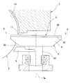
図2の拡大断面図、および、図2のA-A方向矢視図である図3に示すように、上記ゲートロータ3における上記圧縮室C側の一面30に、上記ケーシング1のシール面11が、対向している。
As shown in FIG. 3 which is an enlarged cross-sectional view of FIG. 2 and an AA arrow direction view of FIG. 2, a seal surface 11 of the casing 1 is formed on one surface 30 of the gate rotor 3 on the compression chamber C side. However, they are facing each other.
図3では、上記スクリューロータ2の紙面左側を、上記圧縮室Cへガスを吸入する吸入側とし、上記スクリューロータ2の紙面右側を、上記圧縮室Cからガスを吐出する吐出側とする。
In FIG. 3, the left side of the screw rotor 2 is defined as the suction side for sucking gas into the compression chamber C, and the right side of the screw rotor 2 is defined as the discharge side for discharging gas from the compression chamber C.
上記ケーシング1の上記シール面11は、上記シリンダ10の内面に、連接される面である。上記ケーシング1の上記シール面11は、上記スクリューロータ2の軸2aに平行な方向に延在している。
The sealing surface 11 of the casing 1 is a surface connected to the inner surface of the cylinder 10. The sealing surface 11 of the casing 1 extends in a direction parallel to the shaft 2 a of the screw rotor 2.
上記ゲートロータ3の上記一面30は、上記圧縮室Cの内面の一部を形成している。上記ケーシング1の上記シール面11と上記ゲートロータ3の上記一面30との間には、例えば60μm程度の隙間がある。
The one surface 30 of the gate rotor 3 forms a part of the inner surface of the compression chamber C. There is a gap of, for example, about 60 μm between the seal surface 11 of the casing 1 and the one surface 30 of the gate rotor 3.
上記ケーシング1の上記シール面11の幅に関して、上記スクリューロータ2のガスの吐出側の幅は、上記スクリューロータ2のガスの吸入側の幅よりも、大きい。なお、上記シール面11の幅に関して、上記スクリューロータ2のガスの吐出側の幅は、上記スクリューロータ2のガスの吸入側の幅と同じであってもよい。
Regarding the width of the sealing surface 11 of the casing 1, the width of the screw rotor 2 on the gas discharge side is larger than the width of the screw rotor 2 on the gas suction side. Regarding the width of the seal surface 11, the gas discharge side width of the screw rotor 2 may be the same as the gas suction side width of the screw rotor 2.
上記ゲートロータ3は、ゲートロータシャフト4に取り付けられている。このゲートロータシャフト4は、台部41と、この台部41に取り付けられたシャフト部42とを有する。上記ゲートロータ3における一面30と反対側の他面32は、上記台部41に取り付けられている。
The gate rotor 3 is attached to the gate rotor shaft 4. The gate rotor shaft 4 includes a base portion 41 and a shaft portion 42 attached to the base portion 41. The other surface 32 of the gate rotor 3 opposite to the one surface 30 is attached to the base portion 41.
上記台部41の形状は、上記ゲートロータ3の形状に対応している。すなわち、上記台部41の歯部は、上記ゲートロータ3の歯部31に対応した形状を有し、隣り合う上記歯部31の間の空間Sに対応した形状を有する。上記シャフト部42は、上記ケーシング1に、支持されている。
The shape of the pedestal 41 corresponds to the shape of the gate rotor 3. That is, the tooth portion of the base portion 41 has a shape corresponding to the tooth portion 31 of the gate rotor 3 and has a shape corresponding to the space S between the adjacent tooth portions 31. The shaft portion 42 is supported by the casing 1.
上記ゲートロータ3の他面32側には、シール部5が配置されている。つまり、上記シール部5は、上記ゲートロータ3および上記台部41を挟んで、上記シール面11と反対側にある。上記シール部5は、隣り合う上記歯部31の間の空間Sを塞ぐ。
The seal portion 5 is disposed on the other surface 32 side of the gate rotor 3. That is, the seal portion 5 is on the opposite side of the seal surface 11 with the gate rotor 3 and the base portion 41 interposed therebetween. The seal portion 5 closes the space S between the adjacent tooth portions 31.
上記シール部5は、板状の部材であり、上記ケーシング1に取り付けられている。上記シール部5は、上記台部41から僅かに離隔している。上記シール部5の材質は、例えば、ポリフェニレンサルファイド樹脂である。
The seal portion 5 is a plate-like member and is attached to the casing 1. The seal portion 5 is slightly separated from the base portion 41. The material of the seal portion 5 is, for example, polyphenylene sulfide resin.
上記シール部5の一面50は、上記ゲートロータ3を挟んで上記シール面11に対向し、この一面50の形状は、上記シール面11における上記ゲートロータ3を挟んで上記シール部5に対向する部分の形状に、略一致する。つまり、上記シール部5の一面50の幅に関して、上記スクリューロータ2のガスの吐出側の幅は、上記スクリューロータ2のガスの吸入側の幅よりも、大きい。なお、上記シール部5の一面50の幅に関して、上記スクリューロータ2のガスの吐出側の幅は、上記スクリューロータ2のガスの吸入側の幅と同じであってもよい。
One surface 50 of the seal portion 5 faces the seal surface 11 with the gate rotor 3 interposed therebetween, and the shape of the one surface 50 faces the seal portion 5 with the gate rotor 3 on the seal surface 11 sandwiched. It almost matches the shape of the part. That is, with respect to the width of the one surface 50 of the seal portion 5, the width of the screw rotor 2 on the gas discharge side is larger than the width of the screw rotor 2 on the gas suction side. Regarding the width of the one surface 50 of the seal portion 5, the gas discharge side width of the screw rotor 2 may be the same as the gas suction side width of the screw rotor 2.
上記シール部5は、上記ゲートロータ3の軸3aを含むと共に上記スクリューロータ2の軸2aに直交する平面Pよりも、上記スクリューロータ2の軸2a方向の吐出側に、設けられている。
The seal portion 5 includes the shaft 3a of the gate rotor 3 and is provided on the discharge side in the direction of the shaft 2a of the screw rotor 2 from a plane P orthogonal to the shaft 2a of the screw rotor 2.
上記構成のスクリュー圧縮機によれば、上記ゲートロータ3の上記他面32側に、上記シール部5を配置し、上記シール部5は、上記隣り合う歯部31の間の空間Sを塞ぐので、上記シール部5は、上記圧縮室C内のガスが、上記隣り合う歯部31の間の空間Sを通って、上記ゲートロータ3の上記一面30から上記他面32側に抜け出ることを、阻止する。つまり、上記圧縮室C内のガスが、上記隣り合う歯部31の間の空間Sを通って、上記ゲートロータ3を収納する低圧の空間Sへ、漏れ出ることを防止できる。
According to the screw compressor configured as described above, the seal portion 5 is disposed on the other surface 32 side of the gate rotor 3, and the seal portion 5 closes the space S between the adjacent tooth portions 31. The seal portion 5 allows the gas in the compression chamber C to escape from the one surface 30 of the gate rotor 3 to the other surface 32 side through the space S between the adjacent tooth portions 31. Stop. That is, the gas in the compression chamber C can be prevented from leaking through the space S between the adjacent tooth portions 31 to the low-pressure space S that houses the gate rotor 3.
したがって、上記ゲートロータ3の隣接する歯部31の間の空間Sからのガスの漏れを低減して、圧縮性能を向上できる。
Therefore, the gas leakage from the space S between the adjacent tooth portions 31 of the gate rotor 3 can be reduced, and the compression performance can be improved.
また、上記シール部5における上記ゲートロータ3を挟んで上記シール面11に対向する一面50の形状は、上記シール面11における上記ゲートロータ3を挟んで上記シール部5に対向する部分の形状に、略一致する形状とすれば、上記空間Sを塞ぐことができて、ガスの漏れを効率よく防止することができる。
In addition, the shape of the one surface 50 facing the seal surface 11 across the gate rotor 3 in the seal portion 5 is the shape of the portion facing the seal portion 5 across the gate rotor 3 in the seal surface 11. If the shapes substantially coincide with each other, the space S can be closed, and gas leakage can be efficiently prevented.
また、上記シール部5は、上記ゲートロータ3の軸3aを含むと共に上記スクリューロータ2の軸2aに直交する平面Pよりも、上記スクリューロータ2の軸2a方向の吐出側に、設けられているので、上記シール部5を小さくできて、上記シール部5の取り付けスペースを小さくできる。
The seal portion 5 includes the shaft 3a of the gate rotor 3 and is provided on the discharge side in the direction of the shaft 2a of the screw rotor 2 from a plane P orthogonal to the shaft 2a of the screw rotor 2. Therefore, the seal part 5 can be made small, and the installation space for the seal part 5 can be made small.
つまり、上記圧縮室C内のガスの圧力は、上記スクリューロータ2の吐出側で、高くなり、上記空間Sを通るガス漏れの大部分は、上記スクリューロータ2の吐出側(高圧の圧縮室C)からの漏れであり、上記スクリューロータ2の吸入側(低圧の圧縮室C)からの漏れは、小さい。このため、上記シール部5は、上記スクリューロータ2の吐出側(高圧の圧縮室C)のみに設けてもよい。
That is, the pressure of the gas in the compression chamber C becomes higher on the discharge side of the screw rotor 2, and most of the gas leakage passing through the space S is caused by the discharge side (high-pressure compression chamber C) of the screw rotor 2. The leakage from the suction side (low pressure compression chamber C) of the screw rotor 2 is small. For this reason, the seal portion 5 may be provided only on the discharge side (the high-pressure compression chamber C) of the screw rotor 2.
また、上記シール部5の材質は、ポリフェニレンサルファイド樹脂であるので、上記シール部5が、万一、上記スクリューロータ2や上記ゲートロータシャフト4と接触しても、上記シール部5が削れることで、機械的な損傷を低減することができる。
In addition, since the material of the seal part 5 is polyphenylene sulfide resin, even if the seal part 5 comes into contact with the screw rotor 2 or the gate rotor shaft 4, the seal part 5 is scraped. Mechanical damage can be reduced.
なお、この発明は上述の実施形態に限定されない。例えば、上記シール部5の一面50の形状を、上記シール面11の形状と異なるようにしてもよい。上記シール部5を、上記平面Pよりも、上記スクリューロータ2の軸2a方向の吸入側にも、設けてもよい。上記シール部5を、上記ケーシング1の一部としてもよい。また、上記シール部5の材質は、ポリフェニレンサルファイド樹脂以外であってもよい。また、上記ゲートロータ3の数量を、増減してもよい。
Note that the present invention is not limited to the above-described embodiment. For example, the shape of the one surface 50 of the seal portion 5 may be different from the shape of the seal surface 11. The seal portion 5 may be provided on the suction side in the direction of the axis 2a of the screw rotor 2 with respect to the plane P. The seal portion 5 may be a part of the casing 1. Further, the material of the seal portion 5 may be other than polyphenylene sulfide resin. Further, the quantity of the gate rotor 3 may be increased or decreased.
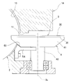
また、図6と図7に示すように、シール部5Aを断面L字状に形成し、このシール部5Aを、ケーシング1Aの貫通孔12の近傍に、ボルトにて、取り付けるようにしてもよい。なお、図6と図7において、図1と図2中の符号と同じ符号の部材は、図1と図2の部材と同じ構成である。
Further, as shown in FIGS. 6 and 7, the seal portion 5A may be formed in an L-shaped cross section, and the seal portion 5A may be attached with a bolt in the vicinity of the through hole 12 of the casing 1A. . 6 and 7, members having the same reference numerals as those in FIGS. 1 and 2 have the same configurations as those in FIGS. 1 and 2.
Claims (4)
- シリンダ(10)を有するケーシング(1)と、
このシリンダ(10)に嵌合されると共に、複数の螺旋状の溝部(21)を外周面に有する円筒状のスクリューロータ(2)と、
このスクリューロータ(2)の溝部(21)に噛合して圧縮室(C)を形成する複数の歯部(31)を外周面に有するゲートロータ(3)と、
上記ゲートロータ(3)における上記圧縮室(C)側の一面(30)と反対側の上記ゲートロータ(3)の他面(32)側に配置されたシール部(5)と
を備え、
上記シール部(5)は、上記ゲートロータ(3)における隣り合う上記歯部(31)の間の空間(S)を塞ぐことを特徴とするスクリュー圧縮機。 A casing (1) having a cylinder (10);
A cylindrical screw rotor (2) fitted into the cylinder (10) and having a plurality of spiral grooves (21) on the outer peripheral surface;
A gate rotor (3) having a plurality of teeth (31) on its outer peripheral surface that mesh with the groove (21) of the screw rotor (2) to form a compression chamber (C);
A seal portion (5) disposed on the other surface (32) side of the gate rotor (3) opposite to the one surface (30) side of the compression chamber (C) side in the gate rotor (3),
The screw compressor, wherein the seal portion (5) closes a space (S) between adjacent tooth portions (31) in the gate rotor (3). - 請求項1に記載のスクリュー圧縮機において、
上記ケーシング(1)は、上記ゲートロータ(3)の上記一面(30)に対向するシール面(11)を有し、
上記シール部(5)における上記ゲートロータ(3)を挟んで上記シール面(11)に対向する一面(50)の形状は、上記シール面(11)における上記ゲートロータ(3)を挟んで上記シール部(5)に対向する部分の形状に、略一致することを特徴とするスクリュー圧縮機。 The screw compressor according to claim 1,
The casing (1) has a seal surface (11) facing the one surface (30) of the gate rotor (3),
The shape of the one surface (50) facing the seal surface (11) across the gate rotor (3) in the seal portion (5) is the same as that of the gate rotor (3) in the seal surface (11). A screw compressor characterized by substantially matching the shape of the portion facing the seal portion (5). - 請求項1または2に記載のスクリュー圧縮機において、
上記スクリューロータ(2)の軸(2a)方向の一端の吸入側から上記圧縮室(C)にガスを吸入する一方、上記スクリューロータ(2)の軸(2a)方向の他端の吐出側から上記圧縮室(C)のガスを吐出し、
上記シール部(5)は、上記ゲートロータ(3)の軸(3a)を含むと共に上記スクリューロータ(2)の軸(2a)に直交する平面(P)よりも、上記スクリューロータ(2)の軸(2a)方向の吐出側に、設けられていることを特徴とするスクリュー圧縮機。 The screw compressor according to claim 1 or 2,
Gas is sucked into the compression chamber (C) from the suction side at one end in the axial (2a) direction of the screw rotor (2), while from the discharge side at the other end in the axial (2a) direction of the screw rotor (2). Discharging the gas in the compression chamber (C),
The seal portion (5) includes the shaft (3a) of the gate rotor (3) and is more flat than the plane (P) perpendicular to the shaft (2a) of the screw rotor (2). A screw compressor provided on the discharge side in the axial (2a) direction. - 請求項1から3の何れか一つに記載のスクリュー圧縮機において、
上記シール部(5)の材質は、ポリフェニレンサルファイド樹脂であることを特徴とするスクリュー圧縮機。 In the screw compressor according to any one of claims 1 to 3,
The screw compressor, wherein the material of the seal part (5) is polyphenylene sulfide resin.
Priority Applications (3)
| Application Number | Priority Date | Filing Date | Title |
|---|---|---|---|
| US12/810,598 US20100278678A1 (en) | 2007-12-28 | 2008-12-26 | Screw compressor |
| CN2008801224534A CN101910639B (en) | 2007-12-28 | 2008-12-26 | Screw compressor |
| EP08867336.3A EP2236833A4 (en) | 2007-12-28 | 2008-12-26 | Screw compressor |
Applications Claiming Priority (4)
| Application Number | Priority Date | Filing Date | Title |
|---|---|---|---|
| JP2007-340540 | 2007-12-28 | ||
| JP2007340540 | 2007-12-28 | ||
| JP2008-328297 | 2008-12-24 | ||
| JP2008328297A JP4400689B2 (en) | 2007-12-28 | 2008-12-24 | Screw compressor |
Publications (1)
| Publication Number | Publication Date |
|---|---|
| WO2009084641A1 true WO2009084641A1 (en) | 2009-07-09 |
Family
ID=40824354
Family Applications (1)
| Application Number | Title | Priority Date | Filing Date |
|---|---|---|---|
| PCT/JP2008/073759 WO2009084641A1 (en) | 2007-12-28 | 2008-12-26 | Screw compressor |
Country Status (5)
| Country | Link |
|---|---|
| US (1) | US20100278678A1 (en) |
| EP (1) | EP2236833A4 (en) |
| JP (1) | JP4400689B2 (en) |
| CN (1) | CN101910639B (en) |
| WO (1) | WO2009084641A1 (en) |
Families Citing this family (2)
| Publication number | Priority date | Publication date | Assignee | Title |
|---|---|---|---|---|
| US9057373B2 (en) | 2011-11-22 | 2015-06-16 | Vilter Manufacturing Llc | Single screw compressor with high output |
| WO2018174100A1 (en) * | 2017-03-21 | 2018-09-27 | ダイキン工業株式会社 | Single-screw compressor |
Citations (9)
| Publication number | Priority date | Publication date | Assignee | Title |
|---|---|---|---|---|
| US2158933A (en) * | 1937-07-26 | 1939-05-16 | Paul E Good | Rotary compressor |
| US3133695A (en) * | 1960-06-22 | 1964-05-19 | Zimmern Fernand | Compressors |
| JPS50131113A (en) * | 1974-04-03 | 1975-10-17 | ||
| JPS5613587U (en) * | 1979-07-11 | 1981-02-05 | ||
| JPS63190585U (en) * | 1987-05-27 | 1988-12-08 | ||
| JPH06179227A (en) * | 1992-12-14 | 1994-06-28 | Matsushita Electric Ind Co Ltd | Gear pump |
| JPH0959592A (en) * | 1995-08-29 | 1997-03-04 | Denso Corp | Seal member |
| JPH10176682A (en) * | 1996-12-17 | 1998-06-30 | Sanyo Electric Co Ltd | Scroll compressor |
| JP3731399B2 (en) | 1999-08-30 | 2006-01-05 | ダイキン工業株式会社 | Screw compressor |
Family Cites Families (5)
| Publication number | Priority date | Publication date | Assignee | Title |
|---|---|---|---|---|
| FR2148677A5 (en) * | 1971-07-30 | 1973-03-23 | Zimmern Bernard | |
| JPS5911759B2 (en) * | 1974-04-15 | 1984-03-17 | 北越工業 (株) | Globoid worm type compressor and expander having pinion teeth assembled so that the whole can be freely displaced in the rotational direction and diametrical direction. |
| US4227867A (en) * | 1978-03-06 | 1980-10-14 | Chicago Pneumatic Tool Company | Globoid-worm compressor with single piece housing |
| US5032068A (en) * | 1988-10-25 | 1991-07-16 | Kurherr Waldemar H | Displacement type rotary system steam turbine engine |
| JP4211871B2 (en) * | 2007-05-23 | 2009-01-21 | ダイキン工業株式会社 | Screw compressor |
-
2008
- 2008-12-24 JP JP2008328297A patent/JP4400689B2/en not_active Expired - Fee Related
- 2008-12-26 EP EP08867336.3A patent/EP2236833A4/en not_active Withdrawn
- 2008-12-26 WO PCT/JP2008/073759 patent/WO2009084641A1/en active Application Filing
- 2008-12-26 CN CN2008801224534A patent/CN101910639B/en not_active Expired - Fee Related
- 2008-12-26 US US12/810,598 patent/US20100278678A1/en not_active Abandoned
Patent Citations (9)
| Publication number | Priority date | Publication date | Assignee | Title |
|---|---|---|---|---|
| US2158933A (en) * | 1937-07-26 | 1939-05-16 | Paul E Good | Rotary compressor |
| US3133695A (en) * | 1960-06-22 | 1964-05-19 | Zimmern Fernand | Compressors |
| JPS50131113A (en) * | 1974-04-03 | 1975-10-17 | ||
| JPS5613587U (en) * | 1979-07-11 | 1981-02-05 | ||
| JPS63190585U (en) * | 1987-05-27 | 1988-12-08 | ||
| JPH06179227A (en) * | 1992-12-14 | 1994-06-28 | Matsushita Electric Ind Co Ltd | Gear pump |
| JPH0959592A (en) * | 1995-08-29 | 1997-03-04 | Denso Corp | Seal member |
| JPH10176682A (en) * | 1996-12-17 | 1998-06-30 | Sanyo Electric Co Ltd | Scroll compressor |
| JP3731399B2 (en) | 1999-08-30 | 2006-01-05 | ダイキン工業株式会社 | Screw compressor |
Non-Patent Citations (1)
| Title |
|---|
| See also references of EP2236833A4 * |
Also Published As
| Publication number | Publication date |
|---|---|
| US20100278678A1 (en) | 2010-11-04 |
| EP2236833A4 (en) | 2014-12-17 |
| JP4400689B2 (en) | 2010-01-20 |
| EP2236833A1 (en) | 2010-10-06 |
| JP2009174523A (en) | 2009-08-06 |
| CN101910639A (en) | 2010-12-08 |
| CN101910639B (en) | 2012-11-14 |
Similar Documents
| Publication | Publication Date | Title |
|---|---|---|
| US10487831B2 (en) | Scroll compressor | |
| US9366253B2 (en) | Scroll compressor and processing method of scroll including a projection on a tip seal and a hole in a tip seal groove | |
| WO2013183436A1 (en) | Gas compressor | |
| AU2005312771A1 (en) | Compressor | |
| WO2017013987A1 (en) | Scroll-type compressor | |
| KR20070083469A (en) | Screw compressor seal | |
| WO2015064612A1 (en) | Scroll-type fluid machine | |
| WO2009084641A1 (en) | Screw compressor | |
| JP4211871B2 (en) | Screw compressor | |
| JP5826686B2 (en) | Gas compressor | |
| JP5195055B2 (en) | Rotary compressor | |
| KR102522649B1 (en) | Scroll compressor | |
| JP6130271B2 (en) | Scroll compressor | |
| JP4325702B2 (en) | Screw compressor | |
| JP2011021535A (en) | Screw compressor | |
| JP2008215245A (en) | Single screw compressor | |
| WO2023210768A1 (en) | Rotary compressor and refrigeration device | |
| CN113847237A (en) | Gear pump or motor | |
| WO2013157328A1 (en) | Gas compressor | |
| JP2012177353A (en) | Multistage compression type rotary compressor and compression type rotary compressor | |
| JP2005535827A (en) | Helical screw rotor compressor | |
| WO2017208833A1 (en) | Scroll-type fluid machine | |
| JP2009275567A (en) | Screw compressor | |
| KR20080054846A (en) | Inner space separate device for scroll compressor | |
| GB2537635A (en) | Pump |
Legal Events
| Date | Code | Title | Description |
|---|---|---|---|
| WWE | Wipo information: entry into national phase |
Ref document number: 200880122453.4 Country of ref document: CN |
|
| 121 | Ep: the epo has been informed by wipo that ep was designated in this application |
Ref document number: 08867336 Country of ref document: EP Kind code of ref document: A1 |
|
| WWE | Wipo information: entry into national phase |
Ref document number: 12810598 Country of ref document: US Ref document number: 2008867336 Country of ref document: EP |
|
| NENP | Non-entry into the national phase |
Ref country code: DE |