WO2009084145A1 - データベースのインデックスキー更新方法及びプログラム - Google Patents
データベースのインデックスキー更新方法及びプログラム Download PDFInfo
- Publication number
- WO2009084145A1 WO2009084145A1 PCT/JP2008/003123 JP2008003123W WO2009084145A1 WO 2009084145 A1 WO2009084145 A1 WO 2009084145A1 JP 2008003123 W JP2008003123 W JP 2008003123W WO 2009084145 A1 WO2009084145 A1 WO 2009084145A1
- Authority
- WO
- WIPO (PCT)
- Prior art keywords
- node
- key
- tree
- search
- data
- Prior art date
- Legal status (The legal status is an assumption and is not a legal conclusion. Google has not performed a legal analysis and makes no representation as to the accuracy of the status listed.)
- Ceased
Links
Images


Classifications
-
- G—PHYSICS
- G06—COMPUTING OR CALCULATING; COUNTING
- G06F—ELECTRIC DIGITAL DATA PROCESSING
- G06F16/00—Information retrieval; Database structures therefor; File system structures therefor
- G06F16/20—Information retrieval; Database structures therefor; File system structures therefor of structured data, e.g. relational data
- G06F16/22—Indexing; Data structures therefor; Storage structures
- G06F16/2228—Indexing structures
- G06F16/2246—Trees, e.g. B+trees
-
- G—PHYSICS
- G06—COMPUTING OR CALCULATING; COUNTING
- G06F—ELECTRIC DIGITAL DATA PROCESSING
- G06F16/00—Information retrieval; Database structures therefor; File system structures therefor
- G06F16/30—Information retrieval; Database structures therefor; File system structures therefor of unstructured textual data
- G06F16/31—Indexing; Data structures therefor; Storage structures
- G06F16/316—Indexing structures
- G06F16/322—Trees
Definitions
- the present invention relates to a method for updating an index key of a database, and a differential data creation method and apparatus, an index key differential data update method and apparatus, and a program related thereto.
- bit string search processing As one of the background arts of the present invention, first, the above-described bit string search processing will be described.
- Various bit string search processing techniques are known. Among these methods, various data structures for storing bit strings have been conventionally devised in order to search bit strings at high speed. As one of such things, a tree structure called a Patricia tree is known.
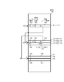
- FIG. 1 shows an example of a Patricia tree used in the above-described conventional search process.
- the Patricia tree node includes an index key, a check bit position of the search key, and left and right link pointers. Although not explicitly shown, it goes without saying that the node includes information for accessing the record corresponding to the index key.
- the node 1750a holding the index key “100010” is the root node, and the check bit position is 0.
- a node 1750b is connected to the left link 1740a of the node 1750a, and a node 1750f is connected to the right link 1741a.
- the index key held by the node 1750b is “010011”, and the check bit position 2030b is 1.
- a node 1750c is connected to the left link 1740b of the node 1750b, and a node 1750d is connected to the right link 1741b.
- the index key held by the node 1750c is “000111”, and the check bit position is 3.
- the index key held by the node 1750d is “011010”, and the check bit position is 2.
- the portion connected by a solid line from the node 1750c indicates the left and right link pointers of the node 1750c, and the left pointer 1740c not connected by the dotted line indicates that the column is blank.
- the connection destination of the dotted line of the right pointer 1741c connected to the dotted line represents the address indicated by the pointer, and in this case indicates that the right pointer designates the node 1750c.
- the right pointer 1741d of the node 1750d points to the node 1750d itself, and the node 1750e is connected to the left link 1740d.
- the index key held by the node 1750e is “010010”, and the check bit position is 5.
- the left pointer 1740e of the node 1750e points to the node 1750b, and the right pointer 1741e points to the node 1750e.
- the index key held by the node 1750f is “101101”, and the check bit position 1730f is 2.
- a node 1750g is connected to the left link 1740f of the node 1750f, and a node 1750h is connected to the right link 1741f.
- the index key held by the node 1750g is “1000011”, and the check bit position 1730g is 5.
- the left pointer 1740g of the node 1750g points to the node 1750a, and the right pointer 1741g points to the node 1750g.
- the index key held by the node 1750h is “101100”, and the check bit position 1730h is 3.
- the left pointer 1740h of the node 1750h points to the node 1750f, and the right pointer 1741h points to the node 1750h.
- search processing using the Patricia tree has advantages such as being able to search only by checking the necessary bits and comparing the entire key only once, but there are always two links from each node. Increase in storage capacity due to the presence of the data, complicating judgment processing due to the presence of a back link, difficulty in data maintenance such as search processing delay and addition / deletion by comparing with an index key for the first time by returning by a back link, etc. There are disadvantages.
- Patent Document 1 As a technique for overcoming the disadvantages of these Patricia trees, for example, there is a technique disclosed in Patent Document 1 below.
- the lower left and right nodes are stored in a continuous area, thereby reducing the storage capacity of the pointer, and a bit indicating whether or not the next link is a back link Is provided at each node to reduce the back link determination process.
- one node always occupies the index key area and the pointer area, and the lower left and right nodes are stored in a continuous area, and one pointer is used.
- the storage capacity of the same capacity as the node needs to be allocated to the left pointer 1740c, the right pointer 1741h, etc., which is the lowermost part of the Patricia tree shown in FIG. It's not big.
- the problem of delay in search processing due to the back link and the difficulty of processing such as additional deletion have not been improved.
- a data update function is essential as a function of the database system. As the amount of data stored in the database increases, for example, if a large amount of data is added to or deleted from an existing database by batch processing, the time required for the operation increases. Yes. There are two modes of updating the database in a batch mode: a mode in which the database is updated by addition, change or deletion data to the existing database, and a mode in which the existing database is completely replaced with a new database.
- the database data supplier does not supply the database update data when the database needs to be updated, but supplies a new version of the database with updated data. It is adopted when doing.
- the database is usually composed of a data portion of the database body and an index for retrieving data from the database body.
- the database update mode includes a mode in which the index part is updated, and even in this part update, the entire index after the update is supplied and may be completely replaced with the index before the update.
- the index data of the new map data purchased from the map data distributor can be updated from the car navigation system distributor or the car dealer center. It is distributed to each mounted car and the index data is updated for each mounted car navigation system. In this way, since the entire new index data is distributed, the amount of data to be distributed is large, and the update time of the map data in each car navigation system becomes long. JP 2001-357070 A
- an object of the present invention is to provide a database update process capable of efficiently updating a database index key when an index key for a new database that replaces the index key of an existing database is supplied. It is to provide a method.
- the applicant of the present invention is a tree used for a bit string search including a root node, a branch node arranged in an adjacent storage area, and a leaf node or a node pair between branch nodes or between leaf nodes.
- the root node is a node representing the starting point of the tree, and when the node of the tree is one, it is a leaf node, when there are two or more nodes of the tree, it is the branch node, and the branch node performs a bit string search.
- search requests such as obtaining a minimum value and a maximum value, and obtaining a value within a certain range.
- the present applicant has proposed, in Japanese Patent Application No. 2006-293619, a method for obtaining the maximum value / minimum value of an index key included in an arbitrary subtree of a coupled node tree.
- An object of the present invention is to realize a high-speed index key update method for a database using the coupled node tree.
- difference data between old data and new data of an index key is created, and new data is created by updating the old data with the difference data.
- the difference tree which is a coupled node tree storing the index key of the old data or the new data as the index key of the leaf node is acquired, and the new data or the index key of the old data is searched from the difference tree as the search key.
- the index key that matches the search key is deleted from the difference tree, and the search key that does not match the index key in the old data is used as the difference data insertion key or delete key.
- the difference data is created by using the index key of the old data remaining in the difference tree after the completion as the deletion key or insertion key of the difference data.
- an update tree which is a coupled node tree storing the index key of the old data as the index key of the leaf node, is acquired, and the delete key extracted from the differential data is updated to the update tree
- the new data is created by inserting the insertion key extracted from the difference data into the update tree.
- differential data can be created at high speed by using a coupled node tree. Since it is not the entire new data but the difference data that is distributed to the site that updates the index key, the amount of data to be distributed can be reduced. Also, by using a coupled node tree for updating the index key, high-speed data updating can be performed.
- the address information of the storage device can be used as the data indicating the link destination position held by the branch node, but it consists of an array element that can store the larger storage capacity of the area occupied by the branch node or leaf node.
- the position of the node can be represented by an array number, and the amount of information on the position information can be reduced.
- FIG. 2A is a diagram illustrating a configuration example of a coupled node tree stored in an array.
- the node 101 is arranged in the array element of array number 10 in the array 100.
- the node 101 includes a node type 102, a discrimination bit position 103, and a representative node number 104.
- the node type 102 is 0, indicating that the node 101 is a branch node. 1 is stored in the discrimination bit position 103.
- the representative node number 104 stores the array element number 20 of the representative node of the link destination node pair.
- the array element number stored in the representative node number may be referred to as a representative node number.
- the array element number stored in the representative node number may be represented by a code attached to the node or a code attached to the node pair.
- the node [0] 112 that is the representative node of the node pair 111 is stored in the array element of the array element number 20. Then, node [1] 113 paired with the representative node is stored in the next adjacent array element (array number 20 + 1). 0 is stored in the node type 114 of the node [0] 112, 3 is stored in the discrimination bit position 115, and 30 is stored in the representative node number 116. Further, 1 is stored in the node type 117 of the node [1] 113, indicating that the node [1] 113 is a leaf node.
- the index key 118 stores “0001”. As described above for the Patricia tree, it is natural that the leaf node includes information for accessing the record corresponding to the index key, but the description is omitted.
- a representative node may be represented by a node [0] and a node paired therewith may be represented by a node [1].
- a node stored in an array element having a certain array number may be referred to as a node having the array number
- an array number of the array element in which the node is stored may be referred to as a node array number.
- the contents of the node pair 121 composed of the node 122 and the node 123 stored in the array elements of the array element numbers 30 and 31 are omitted.
- the 0 or 1 added to the array elements stored in the node [0] 112, the node [1] 113, the node 122, and the node 123 are linked to either node of the node pair when searching with the search key. It shows what to do.
- the search key bit value 0 or 1 at the discrimination bit position of the preceding branch node is linked to the node of the array element number obtained by adding the representative node number. Therefore, by adding the bit value of the discrimination bit position of the search key to the representative node number of the preceding branch node, the array element number of the array element storing the link destination node can be obtained.
- the representative node number is the smaller of the array element numbers where the node pairs are arranged. However, it is obvious that the larger one can be adopted.
- FIG. 2B is a diagram conceptually illustrating a tree structure of a coupled node tree.
- the 6-bit index key shown is the same as that of the Patricia tree illustrated in FIG.
- a reference numeral 210a indicates a root node.
- the root node 210a is a representative node of the node pair 201a arranged at the array element number 220.
- a note pair 201b is arranged below the root node 210a
- a node pair 201c and a node pair 201f are arranged below it
- a node pair 201h and a node pair 201g are arranged below the node pair 201f.
- a node pair 201d is disposed below the node pair 201c, and a node pair 201e is disposed below the node pair 201d.
- the code of 0 or 1 added before each node is the same as the code assigned before the array element described in FIG. 2A.
- the tree is traversed according to the bit value of the discrimination bit position of the search key, and the leaf node to be searched is found.
- the node type 260a of the root node 210a is 0, indicating that it is a branch node, and the discrimination bit position 230a indicates 0.
- the representative node number is 220a, which is the array element number of the array element stored in the representative node 210b of the node pair 201b.
- the node pair 201b is composed of nodes 210b and 211b, and the node types 260b and 261b are both 0, indicating that they are branch nodes. 1 is stored in the discrimination bit position 230b of the node 210b, and the array element number 220b of the array element stored in the representative node 210c of the node pair 201c is stored in the link representative node number.
- this node is a leaf node and therefore includes an index key. “000111” is stored in the index key 250c.
- the node type 261c of the node 211c is 0, the discrimination bit position 231c is 2, and the array element number 221c of the array element stored in the representative node 210d of the node pair 201d is stored in the representative node number.
- the node type 260d of the node 210d is 0, the discrimination bit position 230d is 5, and the array number 220d of the array element in which the representative node 210e of the node pair 201e is stored is stored in the representative node number.
- the node type 261d of the node 211d paired with the node 210d is 1, and “011010” is stored in the index key 251d.
- the node types 260e and 261e of the nodes 210e and 211e of the node pair 201e are both 1, indicating that both are leaf nodes.
- “010010” and “010011” are stored as index keys in the index keys 250e and 251e, respectively. Has been.
- the node types 260f and 261f of the nodes 210f and 211f of the node pair 201f are both 0, and both are branch nodes. 5 and 3 are stored in the discrimination bit positions 230f and 231f, respectively.
- the representative node number of the node 210f stores the array element number 220f of the array element in which the representative node 210g of the node pair 201g is stored, and the representative node number of the node 211f contains the node [0] 210h that is the representative node of the node pair 201h.
- the array element number 221f of the stored array element is stored.
- the node types 260g and 261g of the nodes 210g and 211g of the node pair 201g are both 1, indicating that both are leaf nodes, and “100010” and “1000011” are stored in the respective index keys 250g and 251g. .
- the node type 260h and 261h of the node [0] 210h which is the representative node of the node pair 201h, and the node [1] 211h paired therewith are both 1, indicating that both are leaf nodes, and each index key In “250h” and “251h”, “101011” and “101100” are stored.
- the flow of processing for searching for the index key “100010” from the above tree will be briefly described below.
- the discrimination bit positions are 0, 1, 2,... From the left.
- processing is started from the root node 210a using the bit string “100010” as a search key. Since the discrimination bit position 230a of the root node 210a is 0, it is 1 when the bit value of the discrimination bit position of the search key “100010” is 0 is seen. Therefore, the node 211b stored in the array element having the array element number obtained by adding 1 to the array element number 220a storing the representative node number is linked.
- the discrimination bit position of the search key “100010” is 0 when the bit value of 2 is viewed. Therefore, the array number 221b in which the representative node number is stored Link to the node 210f stored in the array element. Since the node type 260g of the node 210g is 1, indicating that it is a leaf node, when the index key 250g is read and compared with the search key, both are “100010” and match. In this way, a search using a coupled node tree is performed.
- the configuration of a coupled node tree is defined by a set of index keys.
- the discrimination bit position of the root node 210a is 0 because the index keys illustrated in FIG.
- the index key group whose 0th bit is 0 is classified under the node 210b, and the index key group whose 0th bit is 1 is classified under the node 211b.
- the discrimination bit position of the node 211b is 2 because the 0th bit stored in the nodes 211h, 210h, 211g and 210g is all equal to 0 in the 1st bit of the index key, and is different for the first time in the 2nd bit. This reflects the nature of the set of index keys.
- the nodes 210h and 211h are leaf nodes, and “101011” and “101100” are assigned to the index keys 250h and 251h, respectively. "Is stored.
- the coupled node tree structure is determined by the bit value of each bit position of each index key included in the set of index keys. Furthermore, since the node branches to a node having a bit value “1” and a node having a bit value “0” for each bit position having a different bit value, the node [1] side and the depth of the tree When the leaf nodes are traced with priority given to the direction, the index keys stored in them are “101100” of the index key 251h of the node 211h, “101011” of the index key 250h of the node 210h,. The key 250c is “000111” and is sorted in descending order. That is, in the coupled node tree, the index keys are sorted and arranged on the tree.
- the index key follows the route arranged on the coupled node tree. For example, if the search key is “101100”, the node 211h can be reached. Further, as can be imagined from the above description, even when “101101” or “101110” is used as a search key, it is found that the search has failed by reaching the node 211h and comparing with the index key 251h. For example, even when a search is performed with “100100”, the third and fourth bits of the search key are not used in the link paths of the nodes 210a, 211b, and 210f, and the fifth bit of “100100” is 0. The node 210g is reached in the same manner as when searching for “100010”. In this way, branching is performed using the discrimination bit position corresponding to the bit configuration of the index key stored in the coupled node tree.
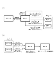
- FIG. 3A is a diagram schematically illustrating the principle of the present invention.
- FIG. 3A (1) illustrates the principle of creating difference data from old data and new data
- FIG. 3A (2) illustrates changing old data to new data using difference data. It is a figure explaining the principle to update.
- a key included in the old data is searched for in all keys included in the new data.
- Keys that match the old data that is, keys that exist in the old data and the new data are not subject to update, and are deleted from the old data.
- a search key that does not match the old data that is, a key added to the new data is taken into the difference data as an insertion key.
- a key that is not retrieved by the new data and remains in the old data that is, a key that does not exist in the new data is taken into the difference data as a deletion key.
- all keys included in the new data are searched for the key included in the old data.
- the new data is generated using all the keys included in the old data. It is clear that the difference data may be created as a search for a key included in. In that case, the key remaining in the new data is taken into the differential data as an insertion key, and the old data that did not match the new data is taken into the differential data as a deletion key.
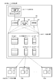
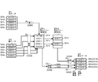
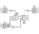
- FIG. 3B is a diagram for explaining a hardware configuration example for carrying out the present invention.
- hardware for carrying out the present invention includes a differential data creation device 300 and differential data update devices 400a to 400x.
- the number of difference data update devices 400a to 400x is arbitrary.
- the difference data creation by the difference data creation device 300 of the present invention is performed by the data processing device 301 including at least the central processing unit 302 and the cache memory 303 using the data storage device 308.
- a search path stack 310 that stores an array 309 in which a coupled node tree is arranged, an array element number in which a node to be traced is stored, an old data storage area 321 that stores old data, and a new data that stores new data
- the data storage device 308 having the data storage region 322 and the differential data storage region 320 for storing the created differential data can be realized by the main storage device 305 or the external storage device 306 or connected via the communication device 307. It is also possible to use a remotely located device.
- the difference data created in the difference data creation device 300 is sent to the difference data update devices 400a to 400x, stored in the respective difference data storage areas 420a to 420x, and the old data stored in the respective index storage areas 421a to 421x. Used to update data to new data.
- the differential data update devices 400a to 400x also include a data processing device and a data storage device having a differential data storage area, an index storage area, and other storage areas.
- the data stored in a certain data storage area is appended with the code of the data storage area so that the difference data stored in the difference data storage area 320 is expressed as the difference data 320, for example. May explain.
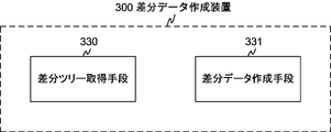
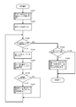
- FIG. 3C is a diagram illustrating a functional block configuration of the difference data creation device 300.
- the difference data creation device 300 includes functional blocks of a difference tree acquisition unit 330 and a difference data creation unit 331. These functional blocks are realized by hardware illustrated in FIG. 3B and software that executes a processing flow described below.
- the difference tree acquisition unit 330 acquires a difference tree in which the index key of the old data or the new data is stored as the index key of the leaf node of the coupled node tree.
- the difference data creation means 331 performs a search using the root node of the difference tree as a search start node and all index keys of new data or old data as search keys, and the index key that is the search result key that matches the search key is the difference tree.
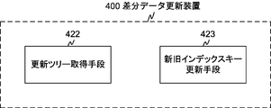
- FIG. 3D is a diagram illustrating a functional block configuration of the difference data update device.
- the differential data update device 400 includes functional blocks of an update tree acquisition unit 422 and an old and new index key update unit 423. These functional blocks are realized by the hardware described for the differential data update devices 400a to 400x shown in FIG. 3B and software for executing the processing flow described below.
- the update tree acquisition unit 422 acquires an update tree in which the index key of the old data is stored as the index key of the leaf node of the coupled node tree.
- the old and new index key update means 423 deletes the deletion key extracted from the difference data created by the difference data creation means 331 from the update tree, and inserts the insertion key extracted from the difference data into the update tree to thereby create an index key for the new data. Is created as an index key of the leaf node, and a new data coupled node tree is created, and the old data is updated to the new data based on the new data coupled node tree.
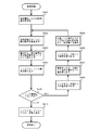
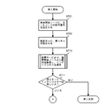
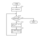
- FIG. 4 is a flowchart showing the basic operation of the bit string search proposed in the above Japanese Patent Application No. 2006-293619 filed by the present applicant.
- step S401 the array element number of the search start node is acquired.
- the array corresponding to the acquired array element number stores arbitrary nodes constituting a coupled node tree.
- the designation of the search start node is performed in various application searches described later.
- the obtained array number of the search start node is set in a search start node setting area (not shown).
- This search start node setting area is used to set various values obtained in the middle of processing as described later. This is one of the “temporary storage devices corresponding to each process for use in the process”.
- the expression “set in a search start node setting area (not shown) instead of the expression “set in a search start node setting area (not shown)”, “get the search start node array number”, “set as search start node” or simply “start search” It may also be described as “set to node”.
- step S402 the obtained array element number is stored in the search path stack 310, and in step S403, the array element corresponding to the array element number is read as a node to be referred to.
- step S404 the node type is extracted from the read node, and in step S405, it is determined whether or not the node type is a branch node. If it is determined in step S405 that the read node is a branch node, the process proceeds to step S406, where information on the discrimination bit position is extracted from the node, and in step S407, a bit value corresponding to the extracted discrimination bit position is obtained. Retrieve from search key.
- step S408 the representative node number is extracted from the node.
- step S409 the bit value extracted from the search key and the representative node number are added, and the process returns to step S402 as a new array number.
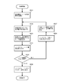
- FIG. 5 is a flowchart showing a process for obtaining the minimum value of the index key stored in the coupled node tree (including the partial tree) proposed in the above-mentioned Japanese Patent Application No. 2006-293619 filed by the present applicant.
- the processing for obtaining the minimum value of the index key from the arrangement of the index key on the tree as described above corresponds to tracing the node [0] from the search start node to the leaf node on the tree.
- step S505 the processing from the acquisition of the array element number of the search start node in step S501 to the determination of the node type in step S505 is the same as the processing in steps S401 to S405 in FIG. If it is determined in step S505 that the node type is a branch node, the process proceeds to step S506, where the representative node number of the array is extracted from the node, and in step S507, the value “0” is added to the extracted representative node number. Then, the result is set as a new array number, and the process returns to step S502. Thereafter, the processing from step S502 to step S507 is repeated until it is determined in step S505 that the node is a leaf node. In step S508, the index key is extracted from the leaf node, and the processing is terminated.
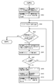
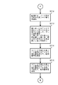
- FIG. 6 is a flowchart showing a process for extracting the index keys stored in the coupled node tree in ascending order.
- the process of extracting the index keys in ascending order is to sequentially follow the leaf nodes from the nodes with priority given to the node [0] side and the depth of the tree among the nodes forming the node pair, and to extract the index keys from each leaf node. Equivalent to.
- step S601 the array element number of the root node is set as the array element number of the search start node, and in step S602, the process for obtaining the minimum index key described with reference to FIG. Get the smallest index key in the tree.
- step S603 the acquired index key is extracted, and the process advances to step S604.
- step S604 it is determined whether or not the stack pointer (hereinafter also referred to as a pointer) of the search path stack 310 points to the array element number of the root node. If the array element number pointed to by the stack pointer is other than the root node, the process proceeds to step S605. In step S605, after the array element number pointed to by the stack pointer is extracted from the search path stack 310, the value of the stack pointer is decremented by one.
- step S606 the node position of which array element of the node pair is stored in the array number is obtained from the array element number extracted in step S605.
- the node position can be obtained from the array number by storing the node [0] in the array element of the even-numbered array.
- step S607 it is determined whether or not the node position obtained in step S606 is on the node [1] side. If it is determined in step S607 that the node is [1], the process returns to step S604, and the processing from step S604 to step S607 is repeated until the node having the array element number indicated by the stack pointer becomes node [0] or the root node. .
- step S607 If it is determined in step S607 that the node is on the node [0] side, the process proceeds to step S608, where 1 is added to the array element number, and the array element number of the node [1] paired with that node is obtained.
- step S609 the array start number of node [1] obtained in step S608 is set in the search start node, and in step S610, a process for obtaining the minimum index key of the subtree having the search start node as the root node is executed. To do.
- the process of step S610 is the same as that of step S602, and the minimum value search process shown in FIG. 5 is used.
- the minimum index key is obtained in step S610, the process returns to step S603, the obtained index key is extracted, and the same processing is repeated until it is determined in step S604 that the pointer indicates the array element number of the root node.
- the pointer of the search path stack 310 points to the array element number of the node including the minimum index key of the coupled node tree.
- a pop operation of the search path stack 310 is performed, and a process of obtaining the minimum value of the index key of the subtree having the node [1] as the search start node and the search start node as the root node among the extracted array number nodes is performed.
- the pop operation and the minimum value search process are repeated until the array element number of the root node of the coupled node tree is extracted as a result of the pop operation of the search path stack 310.
- the array number for the link path is sequentially stored by performing the process of obtaining the minimum value for the nodes under the root node in step S602. For this reason, the node of the search path stack 310 is decremented by 1, and the node [1] that is paired with the node [0] among the nodes of the array element number newly pointed to by the pointer is obtained, and the node of the node [1]
- the index keys are extracted in ascending order.
- the maximum value search can be performed by modifying the minimum value search
- the maximum value search is performed instead of the minimum value search, and the determination of the node [1] is determined as the determination of the node [0].
- the index keys can be extracted in descending order, such as by replacing with.
- FIGS. 7A to 7D illustrate a normal insertion process
- FIG. 7D illustrates a root node insertion process. Since the coupled node tree is generated by the root node insertion process and the normal insertion process, the description of the node insertion process is also the description of the coupled node tree generation process.
- FIG. 7A is a diagram showing the processing flow of the search process that is the first stage of the insert process, and corresponds to the search process shown in FIG. 4 with the root node as the search start node and the insert key as the search key.
- step S701 the array number of the root node is set in the area for setting the array number of the search start node, and in step S702, the insertion key is set as the search key.
- step S710 the search process shown in FIG. 4 is executed to obtain an index key as a search result, and the process advances to step S711.
- step S711 the insertion key is compared with the index key. If they are equal, the insertion key already exists in the coupled node tree, so the insertion fails and the process ends. If not equal, the process proceeds to the next process, the process of step S712 and subsequent steps in FIG. 7B.
- FIG. 7B is a process flow diagram illustrating a process of preparing an array element for a node pair to be inserted.
- step S712 an empty node pair is obtained from the array, and the array element number of the array element to be the representative node of the node pair is acquired.
- step S713 the size of the insertion key and the index key obtained in step S710 are compared. If the insertion key is large, a value 1 is obtained, and a Boolean value 0 is obtained. Proceeding to step S714, an array element number is obtained by adding the Boolean value obtained at step S713 to the array element number of the representative node obtained at step S712. Proceeding to step S715, an array element number is obtained by adding the logical negation value of the Boolean value obtained at step S713 to the array element number of the representative node obtained at step S712.
- the array element number obtained in step S714 is the array element number of the array element in which the leaf node having the insertion key as an index key is stored.
- the array element number obtained in step S715 is the branch node or leaf paired with the leaf node. Of the array element where the node is stored. In other words, the size of the index key and the insertion key stored in the leaf node obtained in the previous search process determines which node of the inserted node pair stores the insertion key. Is done.
- the index key of the search result is “011010” stored in the node 211d.
- a Boolean value is obtained by comparing the size of the insertion key “011011” and the index key “011010” stored in the node 211d.
- the Boolean value 1 is obtained because the insertion key is large, and the representative of the node pair to be inserted.
- a leaf node holding the insertion key is stored in an array element obtained by adding 1 to the node number.
- the index key “011010” is stored in an array element having an array number obtained by adding a logical inversion of a Boolean value obtained by size comparison to a representative node number.
- the node 211d sets the discrimination bit position to 5, and the array element number of the representative node of the node pair in which the representative node number is inserted Branch node.
- the index key of the search result is “011010” stored in the node 211d.
- the insertion key is small, a Boolean value 0 is obtained, and a leaf node holding the insertion key is stored in an array element obtained by adding 0 to the representative node number of the node pair to be inserted. Since the index key “011010” and the insertion key “011001” are different in the fourth bit, the node 211d sets the discrimination bit position to 4 and the array number of the representative node of the node pair into which the representative node number is inserted. Branch node. Next, the process proceeds to step S716 and subsequent steps in FIG. 7C.
- FIG. 7C is a diagram showing a processing flow in which nodes are stored in the array prepared in FIG. 7B, their insertion positions are obtained, the contents of existing nodes are changed, and insertion processing is completed.
- the processing from step S716 to step S723 is processing for obtaining the position of the node pair to be inserted on the coupled node tree, and the processing after step S724 is processing for setting the data in each node and completing the insertion processing. .
- step S716 the bit string comparison between the insertion key and the index key obtained in step S710 is performed by, for example, exclusive OR to obtain a differential bit string. Proceeding to step S717, the bit position of the first non-matching bit viewed from the upper 0th bit is obtained from the difference bit string obtained in step S716.
- a CPU having a priority encoder can input a difference bit string to obtain a mismatched bit position. It is also possible to obtain the bit position of the first non-matching bit by performing processing equivalent to that of the priority encoder in software.
- step S718 it is determined whether the stack pointer of the search path stack points to the array element number of the root node. If so, the process proceeds to step S724. If not, the process proceeds to step S719.
- step S719 the stack pointer of the search path stack is returned by 1, and the array element number stacked there is taken out. Proceeding to step S720, the array element having the array element number extracted at step S719 is read out from the array as a node. Proceeding to step S721, the discrimination bit position is extracted from the node read out at step S720. Next, proceeding to step S722, it is determined whether the discrimination bit position extracted at step S721 is higher than the bit position obtained at step S717.
- the upper positional relationship is a position on the left side of the bit string, that is, a position where the value of the bit position is small. If the determination result in step S722 is negative, the process returns to step S718, and is repeated until the determination in step S718 becomes affirmative or the determination in step S722 becomes affirmative. If the determination in step S722 becomes affirmative, the stack pointer of the route search stack is advanced by 1 in step S723, and the process proceeds to step S724 and subsequent steps.
- a bit string comparison is performed between the index key to be inserted and the index key obtained by the search in order to determine the insertion position of the node pair to be inserted.
- the index key of the search result is “101101” stored in the node 210h.
- the most significant bit position 1 having a different bit value is obtained.
- the positional relationship between the obtained bit position 1 and the discrimination bit position of the branch node stored in the array element having the array element number stacked on the path search stack is sequentially traced back to the path search stack until the discrimination bit position becomes higher.
- the search path stack pointer is advanced by 1 to obtain the array element number of the node 211b.
- the insertion key “111000” is inserted into the link destination of the node 211b.
- the discrimination bit position of the root node is not a higher bit position than the most significant bit position that becomes a different bit value in the previously obtained bit string comparison. This is a case where the values of the upper bits of the index key of the coupled node tree and the bits higher than the discrimination bit position of the root node are all equal.
- the node pair to be inserted becomes a direct link destination of the root node, and the discrimination bit position of the root node is changed to the position of the most significant bit of the insertion key, which is a value different from the existing index key.
- step S724 the array element number pointed to by the stack pointer is extracted from the search path stack.
- step S725 1 (leaf node) is written in the node type of the array element indicated by the array element number obtained in step S714, and the insert key is written in the index key.
- step S726 the array element having the array element number obtained at step S724 is read from the array.
- step S727 the contents read in step S726 are written in the array element having the array element number obtained in step S715.
- step S728 0 (branch node) is obtained for the node type of the array element indicated by the array element number obtained in step S724, the bit position obtained in step S717 is obtained for the discrimination bit position, and the representative node number is obtained in step S712. Write the array element number and end the process.
- the contents of the node 211b are written to the node [0] of the acquired empty node pair (step S727), and the node [1] is inserted into the insertion key “ The leaf node holds 111000 ′′ (step S725). Then, the most significant bit position 1 which becomes a different bit value by bit string comparison is stored in the discrimination bit position of the node 211b, and the array element number of the array element storing the representative node of the acquired node pair is stored in the representative node number. Stored (step S728).
- FIG. 7D is a process flow diagram illustrating the entire node insertion process when adding an index key including the root node insertion process proposed in Japanese Patent Application No. 2006-187827 filed by the present applicant.
- step S101 it is determined whether the array element number of the root node of the coupled node tree requested to be acquired has been registered. If registered, the normal insertion process described with reference to FIGS. 7A to 7C is performed.
- the index keys are sequentially extracted from the set, and the processing of FIGS. 7D and 7A to 7C is repeated, so that the couple of the present invention corresponding to the set of index keys is performed.
- a node tree can be constructed.
- FIGS. 8A and 8B a processing flow for deleting a specific index key from the set of index keys related to the coupled node tree proposed in the above Japanese Patent Application No. 2006-187827 filed by the present applicant. Will be explained.
- step S801 the root node array number is set in the area for setting the search start node array number, and in step S802, the delete key is set as the search key.
- step S810 the search process shown in FIG. 4 is executed to obtain an index key as a search result, and the flow advances to step S811.
- step S811 in FIG. 8A the delete key and the index key are compared. If they are not equal, the index key to be deleted does not exist in the coupled node tree, so the deletion fails and the process ends. If they are equal, the process proceeds to the next process, the process of step S812 and thereafter in FIG. 8B.
- FIG. 8B is a diagram for explaining the processing flow of the latter stage of the deletion processing.
- step S812 it is determined whether two or more array numbers are stored in the search path stack. The fact that two or more array numbers are not stored is, in other words, only one, and the array number is that of the array element in which the root node is stored. In that case, the process proceeds to step S818, and the node pair related to the array element number of the root node obtained in step S801 is deleted. In step S819, the registered root node array element number is deleted, and the process ends.
- step S812 If it is determined in step S812 that two or more array element numbers are stored in the search path stack, the process proceeds to step S813, and a value obtained by inverting the bit value obtained in step S807 to the representative node number obtained in step S808 is set. The added sequence number is obtained. In this process, the array element number in which the node paired with the leaf node storing the index key to be deleted is obtained.
- step S814 the contents of the array element having the array element number obtained in step S813 are read.
- step S815 the stack pointer of the search path stack is returned by 1, and the array element number is extracted.
- step S816 the contents of the array element read in step S814 are overwritten on the array element having the array element number obtained in step S815.
- a branch node that is a link source to the leaf node storing the index key to be deleted is replaced with a node that is paired with the leaf node.
- step S817 the node pair related to the representative node number obtained in step S808 is deleted, and the process ends.
- FIG. 9 is a diagram illustrating an outline of processing for creating difference data using old data and new data according to an embodiment of the present invention.
- the old data 321 includes keys 321a “010010”, 321b “010011”, 321c “100011”, 321d “101011”, and 321e “101100”
- the new data 322 includes keys 322a “010010”, 322b “010110”, 322c “100010”, 322d “1000011”, and 322e “101100”.
- Each update data 380 a to 380 d of the difference data 320 includes items of an update type 381 and an update key 382.
- the update keys 382 of the update data 380a to 380d are keys 321d, 321b, 322c, and 322b as shown in the figure.
- S1001 shown in FIG. 9A corresponds to the processing in step S1001 in the difference data creation processing flow shown in FIG. The same applies to (B) to (E) of FIG. 9 below.
- step S1005 deletion processing of new data with the keys 322a to 322e is performed in step S1005 of the flow shown in FIG.
- the old data keys 321d and 321b remain in the updated difference tree 309-2 without being deleted.
- it is stored in the difference data storage area 320 as an insertion key in step S1007 of FIG.
- the value of the insert key is stored in the update key 382, “i” is stored in the update type 381, and 322c and 322b stored in the update key are the insert keys. Yes.
- the old data keys 321d and 321b remaining in the updated difference tree 309-2 are extracted from the difference tree 309-2 in step S1009 in FIG. 10 and deleted as shown in FIG. Is stored in the difference data storage area 320.
- the value of the delete key is stored in the update key 382
- "d" is stored in the update type 381
- 321d and 321b stored in the update key are shown to be delete keys. Yes.
- the difference tree 309-1 is generated from the old data, and the deletion process is performed using the new data.
- the difference data can be created by generating a difference tree from the new data and performing the deletion process with the old data. .
- new data remaining in the updated difference tree becomes an insertion key, and old data that has failed to be deleted becomes a deletion key.
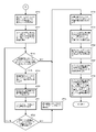
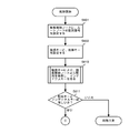
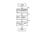
- FIG. 10 is a diagram illustrating a processing flow for creating difference data using old data and new data.
- a processing flow for creating difference data using old and new data will be described with reference to FIG.
- step S1001 all keys of the old data are inserted into the difference tree. Details of this processing will be described later with reference to FIG. If the old data is already stored in the coupled node tree, that is, if the index of the database has the data structure of the coupled node tree, the registered root node is replaced with step 1001. It is only necessary to obtain the sequence number. If the coupled node tree is not stored in the array, position information indicating the position of the root node may be acquired.
- step S1002 new data is set.
- the new data is set by storing the new data supplied from the new data supply source in, for example, the new data storage area 322 shown in FIGS. 3B and 9, but the new data supplied from the supply source. It is also possible to read the key directly from the storage medium storing the key.
- step S1003 it is determined whether all new data has been processed. If all the new data has been processed, the process proceeds to step S1008, and if not, the process proceeds to step S1004.
- step S1004 a key is extracted from the new data set in step S1002.
- step S1005 the extracted key is deleted from the difference tree as a deletion key. This deletion process is shown in FIGS. 8A and 8B.
- step S1006 it is determined whether the deletion in step S1005 is successful. If the deletion is successful, the process returns to step S1003. If the deletion is unsuccessful, difference data is created using the deletion key as an insertion key in step S1007, and the process returns to step S1003. Details of the processing in step S1007 will be described later with reference to FIG.
- step S1008 where all new data has been processed and branched from step S1003, it is determined whether a difference tree is registered. If not registered, the process ends. If registered, all keys of the difference tree are extracted in step S1009, difference data is created as a deletion key, and the process ends. Details of step S1009 will be described later with reference to FIG. Note that the flow described in FIG. 10 is merely an example, and various modifications such as a method for generating a difference tree using new data and a part of the processing order as described above with reference to FIG. It is obvious to those skilled in the art that this is possible.
- FIG. 11 is a diagram for explaining a processing flow for creating a coupled node tree (difference tree) using old data, which is executed in step S1001 of the processing flow for creating difference data using old data and new data shown in FIG. is there.
- old data is set.
- This old data is set by storing old data supplied from the old data supplier and storing it in the old data storage area 321 shown in FIGS. 3B and 9, for example. It is also possible to read the key directly from the storage medium storing the old data.
- step S1102 it is determined whether all keys have been extracted from the old data. If they have been extracted, the process ends. If all the keys have not been extracted from the old data, the key is extracted from the old data in step S1103, and the process proceeds to step S1104 to use the extracted key as an insertion key. Insert. After the insertion processing in step S1104, the loop processing that returns to the determination processing in step S1102 is repeated until all keys have been extracted from the old data.
- FIG. 12 is a diagram illustrating a processing flow for storing update data in difference data.
- the process flow shown in FIG. 12 is applicable to the process of creating difference data using the delete key as an insertion key, which is executed in step S1007 of the process flow of creating difference data using old data and new data shown in FIG. It is. Further, the processing flow shown in FIG. 12 is applicable to the difference data creation processing executed in step S1009 of the processing flow shown in FIG. 10, and whether the data update is insertion or deletion.
- Information and a key value serving as an update key of the difference data.
- an update data setting area including an update type and an update key (not shown) is used as a work area.
- step S1201 the update type is set in the update type in the update data setting area based on information indicating whether the data update is insertion or deletion.
- the caller is step S1007 and the data update is insertion
- “i” is set as the update type.
- step S1202 the value of the key serving as the update key is set as the update key in the update data setting area.
- step S1203 the update data set in the update data setting area in steps S1201 and S1202 is stored in the difference data storage area, and the process ends.
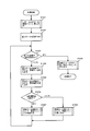
- FIG. 13 illustrates a processing flow for extracting all keys of the difference tree and creating difference data as deletion keys, which is executed in step S1009 of the processing flow for creating difference data using old data and new data shown in FIG. It is a figure to do.
- step S1301 the array element number of the root node of the difference tree is set as the array element number of the search start node.
- the minimum value search shown in FIG. 5 is performed from the search start node to obtain the minimum value of the index key.
- difference data is created using the minimum value obtained in step S1302 as a deletion key.
- the process of step 1303 is realized by a process of deleting update types and storing update data in the difference data shown in FIG. 12 with the update key value as the minimum value obtained by the previous minimum value search.
- step S1303 and steps S1304 to S1310 the minimum value search is repeated from the difference tree, the index key is extracted in ascending order, and step S1303 for generating difference data using the extracted minimum value as a deletion key is repeated. Therefore, the processing from step S1304 to step S1310 is the same as the processing from step S604 to step S610 in the processing flow for extracting the index keys shown in FIG. Note that in the process executed in step S1009 shown in FIG. 10, it is only necessary to extract all the keys remaining in the difference tree. Therefore, the above-described descending order extraction is not limited to the ascending order extraction shown in FIG. It is also possible to adopt.
- the difference data is created from the old data and the new data by the processing described with reference to FIGS.
- FIG. 14 is a diagram illustrating an outline of processing for updating old data to new data using difference data according to an embodiment of the present invention.
- the old data is updated to new data in the differential data update device 400 a illustrated in FIG. 3B using the difference data created from the old data and the new data illustrated in FIG. 9.
- the old data keys 321a “010010”, 321b “010011”, 321c “100011”, 321d “101011”, and 321e “101100” are stored in the index storage area 421a, as with the old data shown in FIG. ing.
- the difference data storage area 420a stores the same data as the update data stored in the difference data storage area shown in FIG.
- S1501 shown in FIG. 14A corresponds to the processing in step S1501 of the processing flow in which old data is updated to new data based on difference data shown in FIG.
- S1501 shown in FIG. 14A corresponds to the processing in step S1501 of the processing flow in which old data is updated to new data based on difference data shown in FIG.
- the update tree 409a-2 includes keys 321a, 321c, and 321e included in the old data, and inserted keys 322b and 322c.
- the insertion process is performed after the deletion process is executed on the update tree 409a-1, but the result is the same regardless of the order of the deletion insertion. Also, various modifications such as taking out only the insertion key from the difference data 420a and creating the update tree 409a-1 before update together with the old data 421a, and then creating the update tree 409a-2 after update by only the deletion process. Is possible.
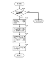
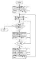
- FIG. 15 is a diagram illustrating a processing flow for updating old data to new data using difference data.
- step S1501 all keys of the old data are inserted into the update tree. This process is realized by the process of creating a coupled node tree with the old data described with reference to FIG.
- step 1501 is replaced with It is only necessary to acquire the registered root node array number or position information indicating the position of the root node. Further, in that case, since the index of the database has a data structure of a coupled node tree, it is also clear that the processing in step S1509 described later is unnecessary.
- difference data is set in step S1502.
- the setting of the difference data is performed by storing the difference data supplied from the supply source that created the difference data by the difference data generation device, for example, in the difference data storage areas 420a to 420x shown in FIG. 3B and FIG. It is also possible to read the key directly from the storage medium storing the new data supplied from the supplier.
- step S1503 it is determined whether all the update data has been processed. If all the update data has been processed, the process proceeds to step S1509. If not, the process proceeds to step S1504. In step S1504, the update data of the difference data set in step S1502 is extracted, and the update key is extracted therefrom.
- step S1505 the update type is extracted from the update data, and in step S1506, the update type extracted in step S1505 is determined. If the update type is deletion, the process proceeds to step S1507. If the update type is insertion, the process proceeds to step S1508.
- step S1507 the deletion process shown in FIGS. 8A and 8B deletes the update key from the update tree using the delete key, and the process returns to step S1503.
- step S1508 the insertion process shown in FIGS. 7A to 7D inserts the update key into the update tree as the insertion key, and the process returns to step S1503.
- step S1509 where all the update data has been processed and branched from step S1503, all the keys of the update tree are extracted as new data by the ascending order extraction process shown in FIG. 6, and the process ends.
- the deletion process and the insertion process are separated according to the update data update type.
- the difference data file is divided into a deletion key file and an insertion key file.
- deletion processing and insertion processing are executed for each file.
- the process of inserting all keys of the old data and the insert key file into the update tree is performed, and the delete process of the update tree is performed by the delete key stored in the delete key file. It is also possible to update the old data to the new data by executing.
Landscapes
- Engineering & Computer Science (AREA)
- Theoretical Computer Science (AREA)
- Software Systems (AREA)
- Data Mining & Analysis (AREA)
- Databases & Information Systems (AREA)
- Physics & Mathematics (AREA)
- General Engineering & Computer Science (AREA)
- General Physics & Mathematics (AREA)
- Information Retrieval, Db Structures And Fs Structures Therefor (AREA)
Priority Applications (3)
| Application Number | Priority Date | Filing Date | Title |
|---|---|---|---|
| EP08866463.6A EP2246796B1 (en) | 2007-12-28 | 2008-10-30 | Database index key update method and program |
| CN2008801224040A CN101911060B (zh) | 2007-12-28 | 2008-10-30 | 数据库的索引关键字更新方法 |
| US12/801,649 US8103697B2 (en) | 2007-12-28 | 2010-06-18 | Database index key update method and program |
Applications Claiming Priority (2)
| Application Number | Priority Date | Filing Date | Title |
|---|---|---|---|
| JP2007338413A JP4498409B2 (ja) | 2007-12-28 | 2007-12-28 | データベースのインデックスキー更新方法及びプログラム |
| JP2007-338413 | 2007-12-28 |
Related Child Applications (1)
| Application Number | Title | Priority Date | Filing Date |
|---|---|---|---|
| US12/801,649 Continuation US8103697B2 (en) | 2007-12-28 | 2010-06-18 | Database index key update method and program |
Publications (1)
| Publication Number | Publication Date |
|---|---|
| WO2009084145A1 true WO2009084145A1 (ja) | 2009-07-09 |
Family
ID=40823881
Family Applications (1)
| Application Number | Title | Priority Date | Filing Date |
|---|---|---|---|
| PCT/JP2008/003123 Ceased WO2009084145A1 (ja) | 2007-12-28 | 2008-10-30 | データベースのインデックスキー更新方法及びプログラム |
Country Status (5)
| Country | Link |
|---|---|
| US (1) | US8103697B2 (enExample) |
| EP (1) | EP2246796B1 (enExample) |
| JP (1) | JP4498409B2 (enExample) |
| CN (1) | CN101911060B (enExample) |
| WO (1) | WO2009084145A1 (enExample) |
Cited By (1)
| Publication number | Priority date | Publication date | Assignee | Title |
|---|---|---|---|---|
| CN111488341A (zh) * | 2020-03-27 | 2020-08-04 | 北京金山云网络技术有限公司 | 数据库索引的管理方法、装置及电子设备 |
Families Citing this family (26)
| Publication number | Priority date | Publication date | Assignee | Title |
|---|---|---|---|---|
| CN102037445B (zh) * | 2008-05-21 | 2014-05-14 | 爱德万测试(新加坡)私人有限公司 | 用于确定重复比特值样式的方法和装置 |
| US9778188B2 (en) | 2009-03-11 | 2017-10-03 | Industrial Technology Research Institute | Apparatus and method for detection and discrimination molecular object |
| US20120144123A1 (en) * | 2010-12-01 | 2012-06-07 | International Business Machines Corporation | Read-ahead processing in networked client-server architecture |
| CN102651007A (zh) * | 2011-02-28 | 2012-08-29 | 国际商业机器公司 | 一种管理数据库索引的方法和装置 |
| US20120233250A1 (en) * | 2011-03-11 | 2012-09-13 | International Business Machines Corporation | Auto-updatable document parts within content management systems |
| US8918651B2 (en) * | 2012-05-14 | 2014-12-23 | International Business Machines Corporation | Cryptographic erasure of selected encrypted data |
| US9529808B1 (en) | 2012-07-16 | 2016-12-27 | Tintri Inc. | Efficient and flexible organization and management of file metadata |
| US9817835B2 (en) | 2013-03-12 | 2017-11-14 | Tintri Inc. | Efficient data synchronization for storage containers |
| CN103150400B (zh) * | 2013-03-27 | 2017-06-06 | 领航动力信息系统有限公司 | 一种基于MapReduce框架的数据筛选方法 |
| US10628378B2 (en) * | 2013-09-03 | 2020-04-21 | Tintri By Ddn, Inc. | Replication of snapshots and clones |
| JP6273892B2 (ja) * | 2014-02-21 | 2018-02-07 | 株式会社リコー | データ検索装置、プログラム、及びデータ検索システム |
| CN105468603B (zh) * | 2014-08-22 | 2019-04-02 | 腾讯科技(深圳)有限公司 | 数据选择方法及装置 |
| US20160063051A1 (en) * | 2014-08-29 | 2016-03-03 | Netapp, Inc. | Methods for persisting data on nonvolatile memory for fast updates and instantaneous recovery and devices thereof |
| US10810168B2 (en) * | 2015-11-24 | 2020-10-20 | Red Hat, Inc. | Allocating file system metadata to storage nodes of distributed file system |
| SG11201811425TA (en) * | 2016-09-22 | 2019-01-30 | Visa Int Service Ass | Techniques for in-memory key range searches |
| CN106776746A (zh) * | 2016-11-14 | 2017-05-31 | 天津南大通用数据技术股份有限公司 | 一种全文索引数据的创建方法及装置 |
| CN108427675B (zh) * | 2017-02-13 | 2022-09-02 | 阿里巴巴集团控股有限公司 | 构建索引的方法及设备 |
| CN107451486B (zh) * | 2017-06-30 | 2021-05-18 | 华为技术有限公司 | 一种文件系统的权限设置方法及装置 |
| CN108804542B (zh) * | 2018-05-16 | 2021-12-07 | 河北天翼科贸发展有限公司 | 一种基于内存运算的快速获取文件增量方法 |
| KR102057055B1 (ko) * | 2018-06-27 | 2019-12-18 | 주식회사 티맥스데이터 | 인덱스 관리 방법 |
| US11100071B2 (en) * | 2018-10-10 | 2021-08-24 | Micron Technology, Inc. | Key-value store tree data block spill with compaction |
| US10915546B2 (en) | 2018-10-10 | 2021-02-09 | Micron Technology, Inc. | Counter-based compaction of key-value store tree data block |
| US10852978B2 (en) | 2018-12-14 | 2020-12-01 | Micron Technology, Inc. | Key-value store using journaling with selective data storage format |
| US10936661B2 (en) | 2018-12-26 | 2021-03-02 | Micron Technology, Inc. | Data tree with order-based node traversal |
| KR102322729B1 (ko) * | 2019-03-04 | 2021-11-05 | 어드밴스드 뉴 테크놀로지스 씨오., 엘티디. | 블록체인 월드 스테이트 머클 패트리샤 트라이 서브트리의 업데이트 |
| CN110489415B (zh) * | 2019-07-23 | 2023-11-03 | 平安科技(深圳)有限公司 | 一种数据更新方法及相关设备 |
Citations (8)
| Publication number | Priority date | Publication date | Assignee | Title |
|---|---|---|---|---|
| JP2001357070A (ja) | 2000-06-13 | 2001-12-26 | Nec Corp | 情報検索方法及び装置 |
| JP2006187827A (ja) | 2005-01-05 | 2006-07-20 | Toyo Tire & Rubber Co Ltd | 研磨パッド |
| JP2006293619A (ja) | 2005-04-08 | 2006-10-26 | Toshiba Tec Corp | コンピュータ装置及びログ出力プログラム |
| WO2008004335A1 (en) * | 2006-07-07 | 2008-01-10 | S.Grants Co., Ltd. | Bit sequence search device, search method, and program |
| WO2008053583A1 (en) * | 2006-10-30 | 2008-05-08 | S.Grants Co., Ltd. | Bit sequence searching method and program |
| WO2008065735A1 (fr) * | 2006-11-28 | 2008-06-05 | S.Grants Co., Ltd. | Procédé de division/connexion pour un arbre de nœuds couplé et programme |
| WO2008090588A1 (ja) * | 2007-01-24 | 2008-07-31 | S. Grants Co., Ltd. | ビット列検索装置、検索方法及びプログラム |
| WO2008132806A1 (ja) * | 2007-04-19 | 2008-11-06 | S.Grants Co., Ltd. | カップルドノードツリーの退避/復元方法、最長一致/最短一致検索方法、ビット列検索方法及び記憶媒体 |
Family Cites Families (16)
| Publication number | Priority date | Publication date | Assignee | Title |
|---|---|---|---|---|
| JP3887867B2 (ja) * | 1997-02-26 | 2007-02-28 | 株式会社日立製作所 | 構造化文書の登録方法 |
| US6029170A (en) * | 1997-11-25 | 2000-02-22 | International Business Machines Corporation | Hybrid tree array data structure and method |
| JP3368237B2 (ja) * | 1999-04-14 | 2003-01-20 | キヤノン株式会社 | コード処理方法、端末装置及び記憶媒体 |
| CA2279119C (en) * | 1999-07-29 | 2004-10-19 | Ibm Canada Limited-Ibm Canada Limitee | Heuristic-based conditional data indexing |
| US6662184B1 (en) * | 1999-09-23 | 2003-12-09 | International Business Machines Corporation | Lock-free wild card search data structure and method |
| US6675163B1 (en) * | 2000-04-06 | 2004-01-06 | International Business Machines Corporation | Full match (FM) search algorithm implementation for a network processor |
| US6594655B2 (en) * | 2001-01-04 | 2003-07-15 | Ezchip Technologies Ltd. | Wildcards in radix- search tree structures |
| US6785699B1 (en) * | 2001-05-04 | 2004-08-31 | Lsi Logic Corporation | Prefix comparator |
| US7702641B2 (en) * | 2001-06-04 | 2010-04-20 | Oracle America, Inc. | Method and system for comparing and updating file trees |
| US7149737B1 (en) * | 2002-04-04 | 2006-12-12 | Ncr Corp. | Locking mechanism using a predefined lock for materialized views in a database system |
| US6934252B2 (en) * | 2002-09-16 | 2005-08-23 | North Carolina State University | Methods and systems for fast binary network address lookups using parent node information stored in routing table entries |
| US6915300B1 (en) * | 2003-12-19 | 2005-07-05 | Xerox Corporation | Method and system for searching indexed string containing a search string |
| US9037553B2 (en) * | 2006-03-16 | 2015-05-19 | Novell, Inc. | System and method for efficient maintenance of indexes for XML files |
| JP2008097215A (ja) | 2006-10-10 | 2008-04-24 | Just Syst Corp | データ処理装置 |
| JP4514768B2 (ja) * | 2007-04-19 | 2010-07-28 | 株式会社エスグランツ | カップルドノードツリーの退避/復元装置、退避/復元方法及びプログラム |
| US20090063400A1 (en) * | 2007-09-05 | 2009-03-05 | International Business Machines Corporation | Apparatus, system, and method for improving update performance for indexing using delta key updates |
-
2007
- 2007-12-28 JP JP2007338413A patent/JP4498409B2/ja not_active Expired - Fee Related
-
2008
- 2008-10-30 WO PCT/JP2008/003123 patent/WO2009084145A1/ja not_active Ceased
- 2008-10-30 CN CN2008801224040A patent/CN101911060B/zh not_active Expired - Fee Related
- 2008-10-30 EP EP08866463.6A patent/EP2246796B1/en not_active Not-in-force
-
2010
- 2010-06-18 US US12/801,649 patent/US8103697B2/en not_active Expired - Fee Related
Patent Citations (8)
| Publication number | Priority date | Publication date | Assignee | Title |
|---|---|---|---|---|
| JP2001357070A (ja) | 2000-06-13 | 2001-12-26 | Nec Corp | 情報検索方法及び装置 |
| JP2006187827A (ja) | 2005-01-05 | 2006-07-20 | Toyo Tire & Rubber Co Ltd | 研磨パッド |
| JP2006293619A (ja) | 2005-04-08 | 2006-10-26 | Toshiba Tec Corp | コンピュータ装置及びログ出力プログラム |
| WO2008004335A1 (en) * | 2006-07-07 | 2008-01-10 | S.Grants Co., Ltd. | Bit sequence search device, search method, and program |
| WO2008053583A1 (en) * | 2006-10-30 | 2008-05-08 | S.Grants Co., Ltd. | Bit sequence searching method and program |
| WO2008065735A1 (fr) * | 2006-11-28 | 2008-06-05 | S.Grants Co., Ltd. | Procédé de division/connexion pour un arbre de nœuds couplé et programme |
| WO2008090588A1 (ja) * | 2007-01-24 | 2008-07-31 | S. Grants Co., Ltd. | ビット列検索装置、検索方法及びプログラム |
| WO2008132806A1 (ja) * | 2007-04-19 | 2008-11-06 | S.Grants Co., Ltd. | カップルドノードツリーの退避/復元方法、最長一致/最短一致検索方法、ビット列検索方法及び記憶媒体 |
Non-Patent Citations (2)
| Title |
|---|
| DAICHI GOTO: "Sawatte Manabu Data Kozo, Tsukatte Minitsuku Algorithm Kochira Java API Kenkyusho! Dai 6 Kai Nibunki to Nibun Tansakuki", JAVA PRESS, vol. 34, 15 February 2004 (2004-02-15), pages 202 - 210, XP008117017 * |
| SHIGEAKI YAZAKI: "Zu de Wakaru! Programming no 10 Dai Kiso Chishiki", NIKKEI SOFTWARE, vol. 6, no. 2, 24 January 2003 (2003-01-24), pages 44 - 45, XP008142270 * |
Cited By (2)
| Publication number | Priority date | Publication date | Assignee | Title |
|---|---|---|---|---|
| CN111488341A (zh) * | 2020-03-27 | 2020-08-04 | 北京金山云网络技术有限公司 | 数据库索引的管理方法、装置及电子设备 |
| CN111488341B (zh) * | 2020-03-27 | 2023-08-22 | 北京金山云网络技术有限公司 | 数据库索引的管理方法、装置及电子设备 |
Also Published As
| Publication number | Publication date |
|---|---|
| US8103697B2 (en) | 2012-01-24 |
| EP2246796A4 (en) | 2011-09-14 |
| US20100262617A1 (en) | 2010-10-14 |
| JP4498409B2 (ja) | 2010-07-07 |
| JP2009157853A (ja) | 2009-07-16 |
| EP2246796A1 (en) | 2010-11-03 |
| CN101911060B (zh) | 2012-09-05 |
| EP2246796B1 (en) | 2013-04-24 |
| CN101911060A (zh) | 2010-12-08 |
Similar Documents
| Publication | Publication Date | Title |
|---|---|---|
| JP4498409B2 (ja) | データベースのインデックスキー更新方法及びプログラム | |
| JP4402120B2 (ja) | ビット列検索装置、検索方法及びプログラム | |
| JP4379894B2 (ja) | カップルドノードツリーの分割/結合方法及びプログラム | |
| JP4502223B2 (ja) | ビット列のマージソート装置、方法及びプログラム | |
| JP4514771B2 (ja) | カップルドノードツリーの最長一致/最短一致検索装置、検索方法及びプログラム | |
| JP4514768B2 (ja) | カップルドノードツリーの退避/復元装置、退避/復元方法及びプログラム | |
| EP2085897B1 (en) | Bit sequence searching method and program | |
| JP4527753B2 (ja) | ビット列検索装置、検索方法及びプログラム | |
| JP4271214B2 (ja) | ビット列検索装置、検索方法及びプログラム | |
| JP4439013B2 (ja) | ビット列検索方法及び検索プログラム | |
| US20100174742A1 (en) | Bit string search apparatus, search method, and program | |
| JP4567754B2 (ja) | ビット列検索装置、検索方法及びプログラム | |
| JP4417431B2 (ja) | カップルドノードツリーの分割/結合方法及びプログラム | |
| JP2009277164A (ja) | ビット列検索装置、検索方法及びプログラム | |
| WO2010125742A1 (ja) | インデックス更新データ作成装置、作成方法及びプログラム | |
| JP2011018296A (ja) | カップルドノードツリーのインデックスキー挿入/削除方法 | |
| JP4813575B2 (ja) | ビット列検索装置 | |
| JP2009199577A (ja) | ビット列検索装置、検索方法及びプログラム |
Legal Events
| Date | Code | Title | Description |
|---|---|---|---|
| WWE | Wipo information: entry into national phase |
Ref document number: 200880122404.0 Country of ref document: CN |
|
| 121 | Ep: the epo has been informed by wipo that ep was designated in this application |
Ref document number: 08866463 Country of ref document: EP Kind code of ref document: A1 |
|
| NENP | Non-entry into the national phase |
Ref country code: DE |
|
| WWE | Wipo information: entry into national phase |
Ref document number: 2008866463 Country of ref document: EP |