WO2009084145A1 - Database index key update method and program - Google Patents
Database index key update method and program Download PDFInfo
- Publication number
- WO2009084145A1 WO2009084145A1 PCT/JP2008/003123 JP2008003123W WO2009084145A1 WO 2009084145 A1 WO2009084145 A1 WO 2009084145A1 JP 2008003123 W JP2008003123 W JP 2008003123W WO 2009084145 A1 WO2009084145 A1 WO 2009084145A1
- Authority
- WO
- WIPO (PCT)
- Prior art keywords
- node
- key
- tree
- search
- data
- Prior art date
Links
- 238000000034 method Methods 0.000 title claims description 165
- 238000003780 insertion Methods 0.000 claims abstract description 93
- 230000037431 insertion Effects 0.000 claims abstract description 93
- 238000012217 deletion Methods 0.000 claims abstract description 58
- 230000037430 deletion Effects 0.000 claims abstract description 58
- 230000008569 process Effects 0.000 claims description 129
- 238000012545 processing Methods 0.000 claims description 100
- 238000013500 data storage Methods 0.000 description 27
- 238000010586 diagram Methods 0.000 description 18
- 241000712062 Patricia Species 0.000 description 10
- 230000001174 ascending effect Effects 0.000 description 7
- 238000000605 extraction Methods 0.000 description 3
- 230000008859 change Effects 0.000 description 2
- 238000004891 communication Methods 0.000 description 2
- 230000006870 function Effects 0.000 description 2
- 238000012986 modification Methods 0.000 description 2
- 230000004048 modification Effects 0.000 description 2
- 238000005516 engineering process Methods 0.000 description 1
- 238000012423 maintenance Methods 0.000 description 1
- 238000004519 manufacturing process Methods 0.000 description 1
Images


Classifications
-
- G—PHYSICS
- G06—COMPUTING; CALCULATING OR COUNTING
- G06F—ELECTRIC DIGITAL DATA PROCESSING
- G06F16/00—Information retrieval; Database structures therefor; File system structures therefor
- G06F16/20—Information retrieval; Database structures therefor; File system structures therefor of structured data, e.g. relational data
- G06F16/22—Indexing; Data structures therefor; Storage structures
- G06F16/2228—Indexing structures
- G06F16/2246—Trees, e.g. B+trees
-
- G—PHYSICS
- G06—COMPUTING; CALCULATING OR COUNTING
- G06F—ELECTRIC DIGITAL DATA PROCESSING
- G06F16/00—Information retrieval; Database structures therefor; File system structures therefor
- G06F16/30—Information retrieval; Database structures therefor; File system structures therefor of unstructured textual data
- G06F16/31—Indexing; Data structures therefor; Storage structures
- G06F16/316—Indexing structures
- G06F16/322—Trees
Definitions
- the present invention relates to a method for updating an index key of a database, and a differential data creation method and apparatus, an index key differential data update method and apparatus, and a program related thereto.
- bit string search processing As one of the background arts of the present invention, first, the above-described bit string search processing will be described.
- Various bit string search processing techniques are known. Among these methods, various data structures for storing bit strings have been conventionally devised in order to search bit strings at high speed. As one of such things, a tree structure called a Patricia tree is known.
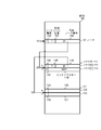
- FIG. 1 shows an example of a Patricia tree used in the above-described conventional search process.
- the Patricia tree node includes an index key, a check bit position of the search key, and left and right link pointers. Although not explicitly shown, it goes without saying that the node includes information for accessing the record corresponding to the index key.
- the node 1750a holding the index key “100010” is the root node, and the check bit position is 0.
- a node 1750b is connected to the left link 1740a of the node 1750a, and a node 1750f is connected to the right link 1741a.
- the index key held by the node 1750b is “010011”, and the check bit position 2030b is 1.
- a node 1750c is connected to the left link 1740b of the node 1750b, and a node 1750d is connected to the right link 1741b.
- the index key held by the node 1750c is “000111”, and the check bit position is 3.
- the index key held by the node 1750d is “011010”, and the check bit position is 2.
- the portion connected by a solid line from the node 1750c indicates the left and right link pointers of the node 1750c, and the left pointer 1740c not connected by the dotted line indicates that the column is blank.
- the connection destination of the dotted line of the right pointer 1741c connected to the dotted line represents the address indicated by the pointer, and in this case indicates that the right pointer designates the node 1750c.
- the right pointer 1741d of the node 1750d points to the node 1750d itself, and the node 1750e is connected to the left link 1740d.
- the index key held by the node 1750e is “010010”, and the check bit position is 5.
- the left pointer 1740e of the node 1750e points to the node 1750b, and the right pointer 1741e points to the node 1750e.
- the index key held by the node 1750f is “101101”, and the check bit position 1730f is 2.
- a node 1750g is connected to the left link 1740f of the node 1750f, and a node 1750h is connected to the right link 1741f.
- the index key held by the node 1750g is “1000011”, and the check bit position 1730g is 5.
- the left pointer 1740g of the node 1750g points to the node 1750a, and the right pointer 1741g points to the node 1750g.
- the index key held by the node 1750h is “101100”, and the check bit position 1730h is 3.
- the left pointer 1740h of the node 1750h points to the node 1750f, and the right pointer 1741h points to the node 1750h.
- search processing using the Patricia tree has advantages such as being able to search only by checking the necessary bits and comparing the entire key only once, but there are always two links from each node. Increase in storage capacity due to the presence of the data, complicating judgment processing due to the presence of a back link, difficulty in data maintenance such as search processing delay and addition / deletion by comparing with an index key for the first time by returning by a back link, etc. There are disadvantages.
- Patent Document 1 As a technique for overcoming the disadvantages of these Patricia trees, for example, there is a technique disclosed in Patent Document 1 below.
- the lower left and right nodes are stored in a continuous area, thereby reducing the storage capacity of the pointer, and a bit indicating whether or not the next link is a back link Is provided at each node to reduce the back link determination process.
- one node always occupies the index key area and the pointer area, and the lower left and right nodes are stored in a continuous area, and one pointer is used.
- the storage capacity of the same capacity as the node needs to be allocated to the left pointer 1740c, the right pointer 1741h, etc., which is the lowermost part of the Patricia tree shown in FIG. It's not big.
- the problem of delay in search processing due to the back link and the difficulty of processing such as additional deletion have not been improved.
- a data update function is essential as a function of the database system. As the amount of data stored in the database increases, for example, if a large amount of data is added to or deleted from an existing database by batch processing, the time required for the operation increases. Yes. There are two modes of updating the database in a batch mode: a mode in which the database is updated by addition, change or deletion data to the existing database, and a mode in which the existing database is completely replaced with a new database.
- the database data supplier does not supply the database update data when the database needs to be updated, but supplies a new version of the database with updated data. It is adopted when doing.
- the database is usually composed of a data portion of the database body and an index for retrieving data from the database body.
- the database update mode includes a mode in which the index part is updated, and even in this part update, the entire index after the update is supplied and may be completely replaced with the index before the update.
- the index data of the new map data purchased from the map data distributor can be updated from the car navigation system distributor or the car dealer center. It is distributed to each mounted car and the index data is updated for each mounted car navigation system. In this way, since the entire new index data is distributed, the amount of data to be distributed is large, and the update time of the map data in each car navigation system becomes long. JP 2001-357070 A
- an object of the present invention is to provide a database update process capable of efficiently updating a database index key when an index key for a new database that replaces the index key of an existing database is supplied. It is to provide a method.
- the applicant of the present invention is a tree used for a bit string search including a root node, a branch node arranged in an adjacent storage area, and a leaf node or a node pair between branch nodes or between leaf nodes.
- the root node is a node representing the starting point of the tree, and when the node of the tree is one, it is a leaf node, when there are two or more nodes of the tree, it is the branch node, and the branch node performs a bit string search.
- search requests such as obtaining a minimum value and a maximum value, and obtaining a value within a certain range.
- the present applicant has proposed, in Japanese Patent Application No. 2006-293619, a method for obtaining the maximum value / minimum value of an index key included in an arbitrary subtree of a coupled node tree.
- An object of the present invention is to realize a high-speed index key update method for a database using the coupled node tree.
- difference data between old data and new data of an index key is created, and new data is created by updating the old data with the difference data.
- the difference tree which is a coupled node tree storing the index key of the old data or the new data as the index key of the leaf node is acquired, and the new data or the index key of the old data is searched from the difference tree as the search key.
- the index key that matches the search key is deleted from the difference tree, and the search key that does not match the index key in the old data is used as the difference data insertion key or delete key.
- the difference data is created by using the index key of the old data remaining in the difference tree after the completion as the deletion key or insertion key of the difference data.
- an update tree which is a coupled node tree storing the index key of the old data as the index key of the leaf node, is acquired, and the delete key extracted from the differential data is updated to the update tree
- the new data is created by inserting the insertion key extracted from the difference data into the update tree.
- differential data can be created at high speed by using a coupled node tree. Since it is not the entire new data but the difference data that is distributed to the site that updates the index key, the amount of data to be distributed can be reduced. Also, by using a coupled node tree for updating the index key, high-speed data updating can be performed.
- the address information of the storage device can be used as the data indicating the link destination position held by the branch node, but it consists of an array element that can store the larger storage capacity of the area occupied by the branch node or leaf node.
- the position of the node can be represented by an array number, and the amount of information on the position information can be reduced.
- FIG. 2A is a diagram illustrating a configuration example of a coupled node tree stored in an array.
- the node 101 is arranged in the array element of array number 10 in the array 100.
- the node 101 includes a node type 102, a discrimination bit position 103, and a representative node number 104.
- the node type 102 is 0, indicating that the node 101 is a branch node. 1 is stored in the discrimination bit position 103.
- the representative node number 104 stores the array element number 20 of the representative node of the link destination node pair.
- the array element number stored in the representative node number may be referred to as a representative node number.
- the array element number stored in the representative node number may be represented by a code attached to the node or a code attached to the node pair.
- the node [0] 112 that is the representative node of the node pair 111 is stored in the array element of the array element number 20. Then, node [1] 113 paired with the representative node is stored in the next adjacent array element (array number 20 + 1). 0 is stored in the node type 114 of the node [0] 112, 3 is stored in the discrimination bit position 115, and 30 is stored in the representative node number 116. Further, 1 is stored in the node type 117 of the node [1] 113, indicating that the node [1] 113 is a leaf node.
- the index key 118 stores “0001”. As described above for the Patricia tree, it is natural that the leaf node includes information for accessing the record corresponding to the index key, but the description is omitted.
- a representative node may be represented by a node [0] and a node paired therewith may be represented by a node [1].
- a node stored in an array element having a certain array number may be referred to as a node having the array number
- an array number of the array element in which the node is stored may be referred to as a node array number.
- the contents of the node pair 121 composed of the node 122 and the node 123 stored in the array elements of the array element numbers 30 and 31 are omitted.
- the 0 or 1 added to the array elements stored in the node [0] 112, the node [1] 113, the node 122, and the node 123 are linked to either node of the node pair when searching with the search key. It shows what to do.
- the search key bit value 0 or 1 at the discrimination bit position of the preceding branch node is linked to the node of the array element number obtained by adding the representative node number. Therefore, by adding the bit value of the discrimination bit position of the search key to the representative node number of the preceding branch node, the array element number of the array element storing the link destination node can be obtained.
- the representative node number is the smaller of the array element numbers where the node pairs are arranged. However, it is obvious that the larger one can be adopted.
- FIG. 2B is a diagram conceptually illustrating a tree structure of a coupled node tree.
- the 6-bit index key shown is the same as that of the Patricia tree illustrated in FIG.
- a reference numeral 210a indicates a root node.
- the root node 210a is a representative node of the node pair 201a arranged at the array element number 220.
- a note pair 201b is arranged below the root node 210a
- a node pair 201c and a node pair 201f are arranged below it
- a node pair 201h and a node pair 201g are arranged below the node pair 201f.
- a node pair 201d is disposed below the node pair 201c, and a node pair 201e is disposed below the node pair 201d.
- the code of 0 or 1 added before each node is the same as the code assigned before the array element described in FIG. 2A.
- the tree is traversed according to the bit value of the discrimination bit position of the search key, and the leaf node to be searched is found.
- the node type 260a of the root node 210a is 0, indicating that it is a branch node, and the discrimination bit position 230a indicates 0.
- the representative node number is 220a, which is the array element number of the array element stored in the representative node 210b of the node pair 201b.
- the node pair 201b is composed of nodes 210b and 211b, and the node types 260b and 261b are both 0, indicating that they are branch nodes. 1 is stored in the discrimination bit position 230b of the node 210b, and the array element number 220b of the array element stored in the representative node 210c of the node pair 201c is stored in the link representative node number.
- this node is a leaf node and therefore includes an index key. “000111” is stored in the index key 250c.
- the node type 261c of the node 211c is 0, the discrimination bit position 231c is 2, and the array element number 221c of the array element stored in the representative node 210d of the node pair 201d is stored in the representative node number.
- the node type 260d of the node 210d is 0, the discrimination bit position 230d is 5, and the array number 220d of the array element in which the representative node 210e of the node pair 201e is stored is stored in the representative node number.
- the node type 261d of the node 211d paired with the node 210d is 1, and “011010” is stored in the index key 251d.
- the node types 260e and 261e of the nodes 210e and 211e of the node pair 201e are both 1, indicating that both are leaf nodes.
- “010010” and “010011” are stored as index keys in the index keys 250e and 251e, respectively. Has been.
- the node types 260f and 261f of the nodes 210f and 211f of the node pair 201f are both 0, and both are branch nodes. 5 and 3 are stored in the discrimination bit positions 230f and 231f, respectively.
- the representative node number of the node 210f stores the array element number 220f of the array element in which the representative node 210g of the node pair 201g is stored, and the representative node number of the node 211f contains the node [0] 210h that is the representative node of the node pair 201h.
- the array element number 221f of the stored array element is stored.
- the node types 260g and 261g of the nodes 210g and 211g of the node pair 201g are both 1, indicating that both are leaf nodes, and “100010” and “1000011” are stored in the respective index keys 250g and 251g. .
- the node type 260h and 261h of the node [0] 210h which is the representative node of the node pair 201h, and the node [1] 211h paired therewith are both 1, indicating that both are leaf nodes, and each index key In “250h” and “251h”, “101011” and “101100” are stored.
- the flow of processing for searching for the index key “100010” from the above tree will be briefly described below.
- the discrimination bit positions are 0, 1, 2,... From the left.
- processing is started from the root node 210a using the bit string “100010” as a search key. Since the discrimination bit position 230a of the root node 210a is 0, it is 1 when the bit value of the discrimination bit position of the search key “100010” is 0 is seen. Therefore, the node 211b stored in the array element having the array element number obtained by adding 1 to the array element number 220a storing the representative node number is linked.
- the discrimination bit position of the search key “100010” is 0 when the bit value of 2 is viewed. Therefore, the array number 221b in which the representative node number is stored Link to the node 210f stored in the array element. Since the node type 260g of the node 210g is 1, indicating that it is a leaf node, when the index key 250g is read and compared with the search key, both are “100010” and match. In this way, a search using a coupled node tree is performed.
- the configuration of a coupled node tree is defined by a set of index keys.
- the discrimination bit position of the root node 210a is 0 because the index keys illustrated in FIG.
- the index key group whose 0th bit is 0 is classified under the node 210b, and the index key group whose 0th bit is 1 is classified under the node 211b.
- the discrimination bit position of the node 211b is 2 because the 0th bit stored in the nodes 211h, 210h, 211g and 210g is all equal to 0 in the 1st bit of the index key, and is different for the first time in the 2nd bit. This reflects the nature of the set of index keys.
- the nodes 210h and 211h are leaf nodes, and “101011” and “101100” are assigned to the index keys 250h and 251h, respectively. "Is stored.
- the coupled node tree structure is determined by the bit value of each bit position of each index key included in the set of index keys. Furthermore, since the node branches to a node having a bit value “1” and a node having a bit value “0” for each bit position having a different bit value, the node [1] side and the depth of the tree When the leaf nodes are traced with priority given to the direction, the index keys stored in them are “101100” of the index key 251h of the node 211h, “101011” of the index key 250h of the node 210h,. The key 250c is “000111” and is sorted in descending order. That is, in the coupled node tree, the index keys are sorted and arranged on the tree.
- the index key follows the route arranged on the coupled node tree. For example, if the search key is “101100”, the node 211h can be reached. Further, as can be imagined from the above description, even when “101101” or “101110” is used as a search key, it is found that the search has failed by reaching the node 211h and comparing with the index key 251h. For example, even when a search is performed with “100100”, the third and fourth bits of the search key are not used in the link paths of the nodes 210a, 211b, and 210f, and the fifth bit of “100100” is 0. The node 210g is reached in the same manner as when searching for “100010”. In this way, branching is performed using the discrimination bit position corresponding to the bit configuration of the index key stored in the coupled node tree.
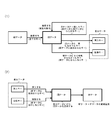
- FIG. 3A is a diagram schematically illustrating the principle of the present invention.
- FIG. 3A (1) illustrates the principle of creating difference data from old data and new data
- FIG. 3A (2) illustrates changing old data to new data using difference data. It is a figure explaining the principle to update.
- a key included in the old data is searched for in all keys included in the new data.
- Keys that match the old data that is, keys that exist in the old data and the new data are not subject to update, and are deleted from the old data.
- a search key that does not match the old data that is, a key added to the new data is taken into the difference data as an insertion key.
- a key that is not retrieved by the new data and remains in the old data that is, a key that does not exist in the new data is taken into the difference data as a deletion key.
- all keys included in the new data are searched for the key included in the old data.
- the new data is generated using all the keys included in the old data. It is clear that the difference data may be created as a search for a key included in. In that case, the key remaining in the new data is taken into the differential data as an insertion key, and the old data that did not match the new data is taken into the differential data as a deletion key.
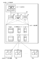
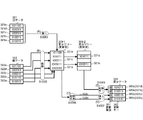
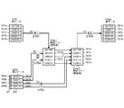
- FIG. 3B is a diagram for explaining a hardware configuration example for carrying out the present invention.
- hardware for carrying out the present invention includes a differential data creation device 300 and differential data update devices 400a to 400x.
- the number of difference data update devices 400a to 400x is arbitrary.
- the difference data creation by the difference data creation device 300 of the present invention is performed by the data processing device 301 including at least the central processing unit 302 and the cache memory 303 using the data storage device 308.
- a search path stack 310 that stores an array 309 in which a coupled node tree is arranged, an array element number in which a node to be traced is stored, an old data storage area 321 that stores old data, and a new data that stores new data
- the data storage device 308 having the data storage region 322 and the differential data storage region 320 for storing the created differential data can be realized by the main storage device 305 or the external storage device 306 or connected via the communication device 307. It is also possible to use a remotely located device.
- the difference data created in the difference data creation device 300 is sent to the difference data update devices 400a to 400x, stored in the respective difference data storage areas 420a to 420x, and the old data stored in the respective index storage areas 421a to 421x. Used to update data to new data.
- the differential data update devices 400a to 400x also include a data processing device and a data storage device having a differential data storage area, an index storage area, and other storage areas.
- the data stored in a certain data storage area is appended with the code of the data storage area so that the difference data stored in the difference data storage area 320 is expressed as the difference data 320, for example. May explain.
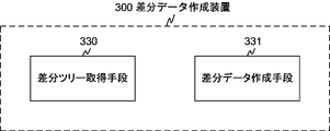
- FIG. 3C is a diagram illustrating a functional block configuration of the difference data creation device 300.
- the difference data creation device 300 includes functional blocks of a difference tree acquisition unit 330 and a difference data creation unit 331. These functional blocks are realized by hardware illustrated in FIG. 3B and software that executes a processing flow described below.
- the difference tree acquisition unit 330 acquires a difference tree in which the index key of the old data or the new data is stored as the index key of the leaf node of the coupled node tree.
- the difference data creation means 331 performs a search using the root node of the difference tree as a search start node and all index keys of new data or old data as search keys, and the index key that is the search result key that matches the search key is the difference tree.
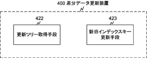
- FIG. 3D is a diagram illustrating a functional block configuration of the difference data update device.
- the differential data update device 400 includes functional blocks of an update tree acquisition unit 422 and an old and new index key update unit 423. These functional blocks are realized by the hardware described for the differential data update devices 400a to 400x shown in FIG. 3B and software for executing the processing flow described below.
- the update tree acquisition unit 422 acquires an update tree in which the index key of the old data is stored as the index key of the leaf node of the coupled node tree.
- the old and new index key update means 423 deletes the deletion key extracted from the difference data created by the difference data creation means 331 from the update tree, and inserts the insertion key extracted from the difference data into the update tree to thereby create an index key for the new data. Is created as an index key of the leaf node, and a new data coupled node tree is created, and the old data is updated to the new data based on the new data coupled node tree.
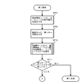
- FIG. 4 is a flowchart showing the basic operation of the bit string search proposed in the above Japanese Patent Application No. 2006-293619 filed by the present applicant.
- step S401 the array element number of the search start node is acquired.
- the array corresponding to the acquired array element number stores arbitrary nodes constituting a coupled node tree.
- the designation of the search start node is performed in various application searches described later.
- the obtained array number of the search start node is set in a search start node setting area (not shown).
- This search start node setting area is used to set various values obtained in the middle of processing as described later. This is one of the “temporary storage devices corresponding to each process for use in the process”.
- the expression “set in a search start node setting area (not shown) instead of the expression “set in a search start node setting area (not shown)”, “get the search start node array number”, “set as search start node” or simply “start search” It may also be described as “set to node”.
- step S402 the obtained array element number is stored in the search path stack 310, and in step S403, the array element corresponding to the array element number is read as a node to be referred to.
- step S404 the node type is extracted from the read node, and in step S405, it is determined whether or not the node type is a branch node. If it is determined in step S405 that the read node is a branch node, the process proceeds to step S406, where information on the discrimination bit position is extracted from the node, and in step S407, a bit value corresponding to the extracted discrimination bit position is obtained. Retrieve from search key.
- step S408 the representative node number is extracted from the node.
- step S409 the bit value extracted from the search key and the representative node number are added, and the process returns to step S402 as a new array number.
- FIG. 5 is a flowchart showing a process for obtaining the minimum value of the index key stored in the coupled node tree (including the partial tree) proposed in the above-mentioned Japanese Patent Application No. 2006-293619 filed by the present applicant.
- the processing for obtaining the minimum value of the index key from the arrangement of the index key on the tree as described above corresponds to tracing the node [0] from the search start node to the leaf node on the tree.
- step S505 the processing from the acquisition of the array element number of the search start node in step S501 to the determination of the node type in step S505 is the same as the processing in steps S401 to S405 in FIG. If it is determined in step S505 that the node type is a branch node, the process proceeds to step S506, where the representative node number of the array is extracted from the node, and in step S507, the value “0” is added to the extracted representative node number. Then, the result is set as a new array number, and the process returns to step S502. Thereafter, the processing from step S502 to step S507 is repeated until it is determined in step S505 that the node is a leaf node. In step S508, the index key is extracted from the leaf node, and the processing is terminated.
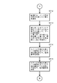
- FIG. 6 is a flowchart showing a process for extracting the index keys stored in the coupled node tree in ascending order.
- the process of extracting the index keys in ascending order is to sequentially follow the leaf nodes from the nodes with priority given to the node [0] side and the depth of the tree among the nodes forming the node pair, and to extract the index keys from each leaf node. Equivalent to.
- step S601 the array element number of the root node is set as the array element number of the search start node, and in step S602, the process for obtaining the minimum index key described with reference to FIG. Get the smallest index key in the tree.
- step S603 the acquired index key is extracted, and the process advances to step S604.
- step S604 it is determined whether or not the stack pointer (hereinafter also referred to as a pointer) of the search path stack 310 points to the array element number of the root node. If the array element number pointed to by the stack pointer is other than the root node, the process proceeds to step S605. In step S605, after the array element number pointed to by the stack pointer is extracted from the search path stack 310, the value of the stack pointer is decremented by one.
- step S606 the node position of which array element of the node pair is stored in the array number is obtained from the array element number extracted in step S605.
- the node position can be obtained from the array number by storing the node [0] in the array element of the even-numbered array.
- step S607 it is determined whether or not the node position obtained in step S606 is on the node [1] side. If it is determined in step S607 that the node is [1], the process returns to step S604, and the processing from step S604 to step S607 is repeated until the node having the array element number indicated by the stack pointer becomes node [0] or the root node. .
- step S607 If it is determined in step S607 that the node is on the node [0] side, the process proceeds to step S608, where 1 is added to the array element number, and the array element number of the node [1] paired with that node is obtained.
- step S609 the array start number of node [1] obtained in step S608 is set in the search start node, and in step S610, a process for obtaining the minimum index key of the subtree having the search start node as the root node is executed. To do.
- the process of step S610 is the same as that of step S602, and the minimum value search process shown in FIG. 5 is used.
- the minimum index key is obtained in step S610, the process returns to step S603, the obtained index key is extracted, and the same processing is repeated until it is determined in step S604 that the pointer indicates the array element number of the root node.
- the pointer of the search path stack 310 points to the array element number of the node including the minimum index key of the coupled node tree.
- a pop operation of the search path stack 310 is performed, and a process of obtaining the minimum value of the index key of the subtree having the node [1] as the search start node and the search start node as the root node among the extracted array number nodes is performed.
- the pop operation and the minimum value search process are repeated until the array element number of the root node of the coupled node tree is extracted as a result of the pop operation of the search path stack 310.
- the array number for the link path is sequentially stored by performing the process of obtaining the minimum value for the nodes under the root node in step S602. For this reason, the node of the search path stack 310 is decremented by 1, and the node [1] that is paired with the node [0] among the nodes of the array element number newly pointed to by the pointer is obtained, and the node of the node [1]
- the index keys are extracted in ascending order.
- the maximum value search can be performed by modifying the minimum value search
- the maximum value search is performed instead of the minimum value search, and the determination of the node [1] is determined as the determination of the node [0].
- the index keys can be extracted in descending order, such as by replacing with.
- FIGS. 7A to 7D illustrate a normal insertion process
- FIG. 7D illustrates a root node insertion process. Since the coupled node tree is generated by the root node insertion process and the normal insertion process, the description of the node insertion process is also the description of the coupled node tree generation process.
- FIG. 7A is a diagram showing the processing flow of the search process that is the first stage of the insert process, and corresponds to the search process shown in FIG. 4 with the root node as the search start node and the insert key as the search key.
- step S701 the array number of the root node is set in the area for setting the array number of the search start node, and in step S702, the insertion key is set as the search key.
- step S710 the search process shown in FIG. 4 is executed to obtain an index key as a search result, and the process advances to step S711.
- step S711 the insertion key is compared with the index key. If they are equal, the insertion key already exists in the coupled node tree, so the insertion fails and the process ends. If not equal, the process proceeds to the next process, the process of step S712 and subsequent steps in FIG. 7B.
- FIG. 7B is a process flow diagram illustrating a process of preparing an array element for a node pair to be inserted.
- step S712 an empty node pair is obtained from the array, and the array element number of the array element to be the representative node of the node pair is acquired.
- step S713 the size of the insertion key and the index key obtained in step S710 are compared. If the insertion key is large, a value 1 is obtained, and a Boolean value 0 is obtained. Proceeding to step S714, an array element number is obtained by adding the Boolean value obtained at step S713 to the array element number of the representative node obtained at step S712. Proceeding to step S715, an array element number is obtained by adding the logical negation value of the Boolean value obtained at step S713 to the array element number of the representative node obtained at step S712.
- the array element number obtained in step S714 is the array element number of the array element in which the leaf node having the insertion key as an index key is stored.
- the array element number obtained in step S715 is the branch node or leaf paired with the leaf node. Of the array element where the node is stored. In other words, the size of the index key and the insertion key stored in the leaf node obtained in the previous search process determines which node of the inserted node pair stores the insertion key. Is done.
- the index key of the search result is “011010” stored in the node 211d.
- a Boolean value is obtained by comparing the size of the insertion key “011011” and the index key “011010” stored in the node 211d.
- the Boolean value 1 is obtained because the insertion key is large, and the representative of the node pair to be inserted.
- a leaf node holding the insertion key is stored in an array element obtained by adding 1 to the node number.
- the index key “011010” is stored in an array element having an array number obtained by adding a logical inversion of a Boolean value obtained by size comparison to a representative node number.
- the node 211d sets the discrimination bit position to 5, and the array element number of the representative node of the node pair in which the representative node number is inserted Branch node.
- the index key of the search result is “011010” stored in the node 211d.
- the insertion key is small, a Boolean value 0 is obtained, and a leaf node holding the insertion key is stored in an array element obtained by adding 0 to the representative node number of the node pair to be inserted. Since the index key “011010” and the insertion key “011001” are different in the fourth bit, the node 211d sets the discrimination bit position to 4 and the array number of the representative node of the node pair into which the representative node number is inserted. Branch node. Next, the process proceeds to step S716 and subsequent steps in FIG. 7C.
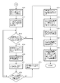
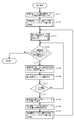
- FIG. 7C is a diagram showing a processing flow in which nodes are stored in the array prepared in FIG. 7B, their insertion positions are obtained, the contents of existing nodes are changed, and insertion processing is completed.
- the processing from step S716 to step S723 is processing for obtaining the position of the node pair to be inserted on the coupled node tree, and the processing after step S724 is processing for setting the data in each node and completing the insertion processing. .
- step S716 the bit string comparison between the insertion key and the index key obtained in step S710 is performed by, for example, exclusive OR to obtain a differential bit string. Proceeding to step S717, the bit position of the first non-matching bit viewed from the upper 0th bit is obtained from the difference bit string obtained in step S716.
- a CPU having a priority encoder can input a difference bit string to obtain a mismatched bit position. It is also possible to obtain the bit position of the first non-matching bit by performing processing equivalent to that of the priority encoder in software.
- step S718 it is determined whether the stack pointer of the search path stack points to the array element number of the root node. If so, the process proceeds to step S724. If not, the process proceeds to step S719.
- step S719 the stack pointer of the search path stack is returned by 1, and the array element number stacked there is taken out. Proceeding to step S720, the array element having the array element number extracted at step S719 is read out from the array as a node. Proceeding to step S721, the discrimination bit position is extracted from the node read out at step S720. Next, proceeding to step S722, it is determined whether the discrimination bit position extracted at step S721 is higher than the bit position obtained at step S717.
- the upper positional relationship is a position on the left side of the bit string, that is, a position where the value of the bit position is small. If the determination result in step S722 is negative, the process returns to step S718, and is repeated until the determination in step S718 becomes affirmative or the determination in step S722 becomes affirmative. If the determination in step S722 becomes affirmative, the stack pointer of the route search stack is advanced by 1 in step S723, and the process proceeds to step S724 and subsequent steps.
- a bit string comparison is performed between the index key to be inserted and the index key obtained by the search in order to determine the insertion position of the node pair to be inserted.
- the index key of the search result is “101101” stored in the node 210h.
- the most significant bit position 1 having a different bit value is obtained.
- the positional relationship between the obtained bit position 1 and the discrimination bit position of the branch node stored in the array element having the array element number stacked on the path search stack is sequentially traced back to the path search stack until the discrimination bit position becomes higher.
- the search path stack pointer is advanced by 1 to obtain the array element number of the node 211b.
- the insertion key “111000” is inserted into the link destination of the node 211b.
- the discrimination bit position of the root node is not a higher bit position than the most significant bit position that becomes a different bit value in the previously obtained bit string comparison. This is a case where the values of the upper bits of the index key of the coupled node tree and the bits higher than the discrimination bit position of the root node are all equal.
- the node pair to be inserted becomes a direct link destination of the root node, and the discrimination bit position of the root node is changed to the position of the most significant bit of the insertion key, which is a value different from the existing index key.
- step S724 the array element number pointed to by the stack pointer is extracted from the search path stack.
- step S725 1 (leaf node) is written in the node type of the array element indicated by the array element number obtained in step S714, and the insert key is written in the index key.
- step S726 the array element having the array element number obtained at step S724 is read from the array.
- step S727 the contents read in step S726 are written in the array element having the array element number obtained in step S715.
- step S728 0 (branch node) is obtained for the node type of the array element indicated by the array element number obtained in step S724, the bit position obtained in step S717 is obtained for the discrimination bit position, and the representative node number is obtained in step S712. Write the array element number and end the process.
- the contents of the node 211b are written to the node [0] of the acquired empty node pair (step S727), and the node [1] is inserted into the insertion key “ The leaf node holds 111000 ′′ (step S725). Then, the most significant bit position 1 which becomes a different bit value by bit string comparison is stored in the discrimination bit position of the node 211b, and the array element number of the array element storing the representative node of the acquired node pair is stored in the representative node number. Stored (step S728).
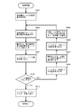
- FIG. 7D is a process flow diagram illustrating the entire node insertion process when adding an index key including the root node insertion process proposed in Japanese Patent Application No. 2006-187827 filed by the present applicant.
- step S101 it is determined whether the array element number of the root node of the coupled node tree requested to be acquired has been registered. If registered, the normal insertion process described with reference to FIGS. 7A to 7C is performed.
- the index keys are sequentially extracted from the set, and the processing of FIGS. 7D and 7A to 7C is repeated, so that the couple of the present invention corresponding to the set of index keys is performed.
- a node tree can be constructed.
- FIGS. 8A and 8B a processing flow for deleting a specific index key from the set of index keys related to the coupled node tree proposed in the above Japanese Patent Application No. 2006-187827 filed by the present applicant. Will be explained.
- step S801 the root node array number is set in the area for setting the search start node array number, and in step S802, the delete key is set as the search key.
- step S810 the search process shown in FIG. 4 is executed to obtain an index key as a search result, and the flow advances to step S811.
- step S811 in FIG. 8A the delete key and the index key are compared. If they are not equal, the index key to be deleted does not exist in the coupled node tree, so the deletion fails and the process ends. If they are equal, the process proceeds to the next process, the process of step S812 and thereafter in FIG. 8B.
- FIG. 8B is a diagram for explaining the processing flow of the latter stage of the deletion processing.
- step S812 it is determined whether two or more array numbers are stored in the search path stack. The fact that two or more array numbers are not stored is, in other words, only one, and the array number is that of the array element in which the root node is stored. In that case, the process proceeds to step S818, and the node pair related to the array element number of the root node obtained in step S801 is deleted. In step S819, the registered root node array element number is deleted, and the process ends.
- step S812 If it is determined in step S812 that two or more array element numbers are stored in the search path stack, the process proceeds to step S813, and a value obtained by inverting the bit value obtained in step S807 to the representative node number obtained in step S808 is set. The added sequence number is obtained. In this process, the array element number in which the node paired with the leaf node storing the index key to be deleted is obtained.
- step S814 the contents of the array element having the array element number obtained in step S813 are read.
- step S815 the stack pointer of the search path stack is returned by 1, and the array element number is extracted.
- step S816 the contents of the array element read in step S814 are overwritten on the array element having the array element number obtained in step S815.
- a branch node that is a link source to the leaf node storing the index key to be deleted is replaced with a node that is paired with the leaf node.
- step S817 the node pair related to the representative node number obtained in step S808 is deleted, and the process ends.
- FIG. 9 is a diagram illustrating an outline of processing for creating difference data using old data and new data according to an embodiment of the present invention.
- the old data 321 includes keys 321a “010010”, 321b “010011”, 321c “100011”, 321d “101011”, and 321e “101100”
- the new data 322 includes keys 322a “010010”, 322b “010110”, 322c “100010”, 322d “1000011”, and 322e “101100”.
- Each update data 380 a to 380 d of the difference data 320 includes items of an update type 381 and an update key 382.
- the update keys 382 of the update data 380a to 380d are keys 321d, 321b, 322c, and 322b as shown in the figure.
- S1001 shown in FIG. 9A corresponds to the processing in step S1001 in the difference data creation processing flow shown in FIG. The same applies to (B) to (E) of FIG. 9 below.
- step S1005 deletion processing of new data with the keys 322a to 322e is performed in step S1005 of the flow shown in FIG.
- the old data keys 321d and 321b remain in the updated difference tree 309-2 without being deleted.
- it is stored in the difference data storage area 320 as an insertion key in step S1007 of FIG.
- the value of the insert key is stored in the update key 382, “i” is stored in the update type 381, and 322c and 322b stored in the update key are the insert keys. Yes.
- the old data keys 321d and 321b remaining in the updated difference tree 309-2 are extracted from the difference tree 309-2 in step S1009 in FIG. 10 and deleted as shown in FIG. Is stored in the difference data storage area 320.
- the value of the delete key is stored in the update key 382
- "d" is stored in the update type 381
- 321d and 321b stored in the update key are shown to be delete keys. Yes.
- the difference tree 309-1 is generated from the old data, and the deletion process is performed using the new data.
- the difference data can be created by generating a difference tree from the new data and performing the deletion process with the old data. .
- new data remaining in the updated difference tree becomes an insertion key, and old data that has failed to be deleted becomes a deletion key.
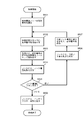
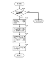
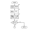
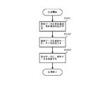
- FIG. 10 is a diagram illustrating a processing flow for creating difference data using old data and new data.
- a processing flow for creating difference data using old and new data will be described with reference to FIG.
- step S1001 all keys of the old data are inserted into the difference tree. Details of this processing will be described later with reference to FIG. If the old data is already stored in the coupled node tree, that is, if the index of the database has the data structure of the coupled node tree, the registered root node is replaced with step 1001. It is only necessary to obtain the sequence number. If the coupled node tree is not stored in the array, position information indicating the position of the root node may be acquired.
- step S1002 new data is set.
- the new data is set by storing the new data supplied from the new data supply source in, for example, the new data storage area 322 shown in FIGS. 3B and 9, but the new data supplied from the supply source. It is also possible to read the key directly from the storage medium storing the key.
- step S1003 it is determined whether all new data has been processed. If all the new data has been processed, the process proceeds to step S1008, and if not, the process proceeds to step S1004.
- step S1004 a key is extracted from the new data set in step S1002.
- step S1005 the extracted key is deleted from the difference tree as a deletion key. This deletion process is shown in FIGS. 8A and 8B.
- step S1006 it is determined whether the deletion in step S1005 is successful. If the deletion is successful, the process returns to step S1003. If the deletion is unsuccessful, difference data is created using the deletion key as an insertion key in step S1007, and the process returns to step S1003. Details of the processing in step S1007 will be described later with reference to FIG.
- step S1008 where all new data has been processed and branched from step S1003, it is determined whether a difference tree is registered. If not registered, the process ends. If registered, all keys of the difference tree are extracted in step S1009, difference data is created as a deletion key, and the process ends. Details of step S1009 will be described later with reference to FIG. Note that the flow described in FIG. 10 is merely an example, and various modifications such as a method for generating a difference tree using new data and a part of the processing order as described above with reference to FIG. It is obvious to those skilled in the art that this is possible.
- FIG. 11 is a diagram for explaining a processing flow for creating a coupled node tree (difference tree) using old data, which is executed in step S1001 of the processing flow for creating difference data using old data and new data shown in FIG. is there.
- old data is set.
- This old data is set by storing old data supplied from the old data supplier and storing it in the old data storage area 321 shown in FIGS. 3B and 9, for example. It is also possible to read the key directly from the storage medium storing the old data.
- step S1102 it is determined whether all keys have been extracted from the old data. If they have been extracted, the process ends. If all the keys have not been extracted from the old data, the key is extracted from the old data in step S1103, and the process proceeds to step S1104 to use the extracted key as an insertion key. Insert. After the insertion processing in step S1104, the loop processing that returns to the determination processing in step S1102 is repeated until all keys have been extracted from the old data.
- FIG. 12 is a diagram illustrating a processing flow for storing update data in difference data.
- the process flow shown in FIG. 12 is applicable to the process of creating difference data using the delete key as an insertion key, which is executed in step S1007 of the process flow of creating difference data using old data and new data shown in FIG. It is. Further, the processing flow shown in FIG. 12 is applicable to the difference data creation processing executed in step S1009 of the processing flow shown in FIG. 10, and whether the data update is insertion or deletion.
- Information and a key value serving as an update key of the difference data.
- an update data setting area including an update type and an update key (not shown) is used as a work area.
- step S1201 the update type is set in the update type in the update data setting area based on information indicating whether the data update is insertion or deletion.
- the caller is step S1007 and the data update is insertion
- “i” is set as the update type.
- step S1202 the value of the key serving as the update key is set as the update key in the update data setting area.
- step S1203 the update data set in the update data setting area in steps S1201 and S1202 is stored in the difference data storage area, and the process ends.
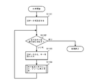
- FIG. 13 illustrates a processing flow for extracting all keys of the difference tree and creating difference data as deletion keys, which is executed in step S1009 of the processing flow for creating difference data using old data and new data shown in FIG. It is a figure to do.
- step S1301 the array element number of the root node of the difference tree is set as the array element number of the search start node.
- the minimum value search shown in FIG. 5 is performed from the search start node to obtain the minimum value of the index key.
- difference data is created using the minimum value obtained in step S1302 as a deletion key.
- the process of step 1303 is realized by a process of deleting update types and storing update data in the difference data shown in FIG. 12 with the update key value as the minimum value obtained by the previous minimum value search.
- step S1303 and steps S1304 to S1310 the minimum value search is repeated from the difference tree, the index key is extracted in ascending order, and step S1303 for generating difference data using the extracted minimum value as a deletion key is repeated. Therefore, the processing from step S1304 to step S1310 is the same as the processing from step S604 to step S610 in the processing flow for extracting the index keys shown in FIG. Note that in the process executed in step S1009 shown in FIG. 10, it is only necessary to extract all the keys remaining in the difference tree. Therefore, the above-described descending order extraction is not limited to the ascending order extraction shown in FIG. It is also possible to adopt.
- the difference data is created from the old data and the new data by the processing described with reference to FIGS.
- FIG. 14 is a diagram illustrating an outline of processing for updating old data to new data using difference data according to an embodiment of the present invention.
- the old data is updated to new data in the differential data update device 400 a illustrated in FIG. 3B using the difference data created from the old data and the new data illustrated in FIG. 9.
- the old data keys 321a “010010”, 321b “010011”, 321c “100011”, 321d “101011”, and 321e “101100” are stored in the index storage area 421a, as with the old data shown in FIG. ing.
- the difference data storage area 420a stores the same data as the update data stored in the difference data storage area shown in FIG.
- S1501 shown in FIG. 14A corresponds to the processing in step S1501 of the processing flow in which old data is updated to new data based on difference data shown in FIG.
- S1501 shown in FIG. 14A corresponds to the processing in step S1501 of the processing flow in which old data is updated to new data based on difference data shown in FIG.
- the update tree 409a-2 includes keys 321a, 321c, and 321e included in the old data, and inserted keys 322b and 322c.
- the insertion process is performed after the deletion process is executed on the update tree 409a-1, but the result is the same regardless of the order of the deletion insertion. Also, various modifications such as taking out only the insertion key from the difference data 420a and creating the update tree 409a-1 before update together with the old data 421a, and then creating the update tree 409a-2 after update by only the deletion process. Is possible.
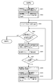
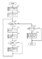
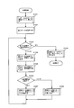
- FIG. 15 is a diagram illustrating a processing flow for updating old data to new data using difference data.
- step S1501 all keys of the old data are inserted into the update tree. This process is realized by the process of creating a coupled node tree with the old data described with reference to FIG.
- step 1501 is replaced with It is only necessary to acquire the registered root node array number or position information indicating the position of the root node. Further, in that case, since the index of the database has a data structure of a coupled node tree, it is also clear that the processing in step S1509 described later is unnecessary.
- difference data is set in step S1502.
- the setting of the difference data is performed by storing the difference data supplied from the supply source that created the difference data by the difference data generation device, for example, in the difference data storage areas 420a to 420x shown in FIG. 3B and FIG. It is also possible to read the key directly from the storage medium storing the new data supplied from the supplier.
- step S1503 it is determined whether all the update data has been processed. If all the update data has been processed, the process proceeds to step S1509. If not, the process proceeds to step S1504. In step S1504, the update data of the difference data set in step S1502 is extracted, and the update key is extracted therefrom.
- step S1505 the update type is extracted from the update data, and in step S1506, the update type extracted in step S1505 is determined. If the update type is deletion, the process proceeds to step S1507. If the update type is insertion, the process proceeds to step S1508.
- step S1507 the deletion process shown in FIGS. 8A and 8B deletes the update key from the update tree using the delete key, and the process returns to step S1503.
- step S1508 the insertion process shown in FIGS. 7A to 7D inserts the update key into the update tree as the insertion key, and the process returns to step S1503.
- step S1509 where all the update data has been processed and branched from step S1503, all the keys of the update tree are extracted as new data by the ascending order extraction process shown in FIG. 6, and the process ends.
- the deletion process and the insertion process are separated according to the update data update type.
- the difference data file is divided into a deletion key file and an insertion key file.
- deletion processing and insertion processing are executed for each file.
- the process of inserting all keys of the old data and the insert key file into the update tree is performed, and the delete process of the update tree is performed by the delete key stored in the delete key file. It is also possible to update the old data to the new data by executing.
Abstract
When an index key is supplied for a new database to replace an index key of an existing database, it is possible to effectively update the index key of the database. An index key of new data is used to perform deletion from a coupled node tree containing an index key of old data as a leaf node index key and to create difference data between the new data formed by an insert key and a delete key and the old data. New data is created by executing deletion and insertion of the delete key and the insert key extracted from the difference data on the coupled node tree containing the index key of the old data as the leaf node index key.
Description
本発明は、データベースのインデックスキーの更新方法、及びそれに関連した、差分データ作成方法と装置、インデックスキーの差分データ更新方法と装置、さらにプログラムに関する。
The present invention relates to a method for updating an index key of a database, and a differential data creation method and apparatus, an index key differential data update method and apparatus, and a program related thereto.
近年、社会の情報化が進展し、大規模なデータベースが各所で利用されるようになってきている。このような大規模なデータベースからレコードを検索するには、各レコードの記憶されたアドレスと対応づけられたレコード内の項目をインデックスキーとして検索をし、所望のレコードを探し出すことが通例である。また、全文検索における文字列も、文書のインデックスキーと見なすことができる。
そして、それらのインデックスキーはビット列で表現されることから、データベースの検索はビット列の検索に帰着されるということができる。 In recent years, with the progress of informatization of society, large-scale databases are being used in various places. In order to search for a record from such a large database, it is usual to search for an item in the record associated with the stored address of each record using an index key to find a desired record. A character string in full-text search can also be regarded as a document index key.
Since these index keys are expressed by bit strings, it can be said that a database search is reduced to a bit string search.
本発明の背景技術の1つとして、まず上述のビット列の検索処理について説明する。
ビット列の検索処理手法については、種々のものが知られている。それらのなかでも、ビット列の検索を高速に行うために、ビット列を記憶するデータ構造を種々に工夫することが従来から行われている。このようなものの一つとして、パトリシアツリーという木構造が知られている。 As one of the background arts of the present invention, first, the above-described bit string search processing will be described.
Various bit string search processing techniques are known. Among these methods, various data structures for storing bit strings have been conventionally devised in order to search bit strings at high speed. As one of such things, a tree structure called a Patricia tree is known.
図1は、上述の従来の検索処理に用いられているパトリシアツリーの一例を示すものである。パトリシアツリーのノードは、インデックスキー、検索キーの検査ビット位置、左右のリンクポインタを含んで構成される。明示はされていないが、ノードにはインデックスキーに対応するレコードにアクセスするための情報が含まれていることは勿論である。
FIG. 1 shows an example of a Patricia tree used in the above-described conventional search process. The Patricia tree node includes an index key, a check bit position of the search key, and left and right link pointers. Although not explicitly shown, it goes without saying that the node includes information for accessing the record corresponding to the index key.
図1の例では、インデックスキー“100010”を保持するノード1750aがルートノードとなっており、その検査ビット位置は0である。ノード1750aの左リンク1740aにはノード1750bが接続され、右リンク1741aにはノード1750fが接続されている。
ノード1750bの保持するインデックスキーは“010011”であり、検査ビット位置2030bは1である。ノード1750bの左リンク1740bにはノード1750cが、右リンク1741bにはノード1750dが接続されている。ノード1750cが保持するインデックスキーは“000111”、検査ビット位置は3である。ノード1750dが保持するインデックスキーは“011010”、検査ビット位置は2である。 In the example of FIG. 1, the node 1750a holding the index key “100010” is the root node, and the check bit position is 0. Anode 1750b is connected to the left link 1740a of the node 1750a, and a node 1750f is connected to the right link 1741a.
The index key held by thenode 1750b is “010011”, and the check bit position 2030b is 1. A node 1750c is connected to the left link 1740b of the node 1750b, and a node 1750d is connected to the right link 1741b. The index key held by the node 1750c is “000111”, and the check bit position is 3. The index key held by the node 1750d is “011010”, and the check bit position is 2.
ノード1750bの保持するインデックスキーは“010011”であり、検査ビット位置2030bは1である。ノード1750bの左リンク1740bにはノード1750cが、右リンク1741bにはノード1750dが接続されている。ノード1750cが保持するインデックスキーは“000111”、検査ビット位置は3である。ノード1750dが保持するインデックスキーは“011010”、検査ビット位置は2である。 In the example of FIG. 1, the node 1750a holding the index key “100010” is the root node, and the check bit position is 0. A
The index key held by the
ノード1750cから実線で接続された部分はノード1750cの左右のリンクポインタを示すものであり、点線の接続されていない左ポインタ1740cは、その欄が空欄であることを示している。点線の接続された右ポインタ1741cの点線の接続先は、ポインタの示すアドレスを表しており、今の場合ノード1750cを右ポインタが指定していることを表している。
ノード1750dの右ポインタ1741dはノード1750d自身を指しており、左リンク1740dにはノード1750eが接続されている。ノード1750eの保持するインデックスキーは“010010”、検査ビット位置は5である。ノード1750eの左ポインタ1740eはノード1750bを、右ポインタ1741eはノード1750eを指している。 The portion connected by a solid line from thenode 1750c indicates the left and right link pointers of the node 1750c, and the left pointer 1740c not connected by the dotted line indicates that the column is blank. The connection destination of the dotted line of the right pointer 1741c connected to the dotted line represents the address indicated by the pointer, and in this case indicates that the right pointer designates the node 1750c.
Theright pointer 1741d of the node 1750d points to the node 1750d itself, and the node 1750e is connected to the left link 1740d. The index key held by the node 1750e is “010010”, and the check bit position is 5. The left pointer 1740e of the node 1750e points to the node 1750b, and the right pointer 1741e points to the node 1750e.
ノード1750dの右ポインタ1741dはノード1750d自身を指しており、左リンク1740dにはノード1750eが接続されている。ノード1750eの保持するインデックスキーは“010010”、検査ビット位置は5である。ノード1750eの左ポインタ1740eはノード1750bを、右ポインタ1741eはノード1750eを指している。 The portion connected by a solid line from the
The
また、ノード1750fの保持するインデックスキーは“101011”であり、検査ビット位置1730fは2である。ノード1750fの左リンク1740fにはノード1750gが、右リンク1741fにはノード1750hが接続されている。
ノード1750gの保持するインデックスキーは“100011”であり、検査ビット位置1730gは5である。ノード1750gの左ポインタ1740gはノード1750aを、右ポインタ1741gはノード1750gを指している。
ノード1750hの保持するインデックスキーは“101100”であり、検査ビット位置1730hは3である。ノード1750hの左ポインタ1740hはノード1750fを、右ポインタ1741hはノード1750hを指している。 Further, the index key held by thenode 1750f is “101101”, and the check bit position 1730f is 2. A node 1750g is connected to the left link 1740f of the node 1750f, and a node 1750h is connected to the right link 1741f.
The index key held by thenode 1750g is “1000011”, and the check bit position 1730g is 5. The left pointer 1740g of the node 1750g points to the node 1750a, and the right pointer 1741g points to the node 1750g.
The index key held by thenode 1750h is “101100”, and the check bit position 1730h is 3. The left pointer 1740h of the node 1750h points to the node 1750f, and the right pointer 1741h points to the node 1750h.
ノード1750gの保持するインデックスキーは“100011”であり、検査ビット位置1730gは5である。ノード1750gの左ポインタ1740gはノード1750aを、右ポインタ1741gはノード1750gを指している。
ノード1750hの保持するインデックスキーは“101100”であり、検査ビット位置1730hは3である。ノード1750hの左ポインタ1740hはノード1750fを、右ポインタ1741hはノード1750hを指している。 Further, the index key held by the
The index key held by the
The index key held by the
図1の例では、ルートノード1750aからツリーを降りるにしたがって、各ノードの検査ビット位置が大きくなるように構成されている。
ある検索キーで検索を行うとき、ルートノードから順次各ノードに保持される検索キーの検査ビット位置を検査していき、検査ビット位置のビット値が1であるか0であるか判定を行い、1であれば右リンクをたどり、0であれば左リンクをたどる。そして、リンク先のノードの検査ビット位置がリンク元のノードの検査ビット位置より大きくなければ、すなわち、リンク先が下方でなく上方に戻れば(図1において点線で示されたこの逆戻りのリンクをバックリンクという)、リンク先のノードのインデックスキーと検索キーの比較を行う。比較の結果、等しければ検索成功であり、等しくなければ検索失敗であることが保証されている。 In the example of FIG. 1, the check bit position of each node is configured to increase as the tree descends from the root node 1750a.
When performing a search with a certain search key, the check bit position of the search key held in each node is sequentially checked from the root node, and it is determined whether the bit value of the check bit position is 1 or 0, If it is 1, follow the right link, if it is 0, follow the left link. If the check bit position of the link destination node is not larger than the check bit position of the link source node, that is, if the link destination returns upward rather than downward (the reverse link indicated by the dotted line in FIG. The index key of the link destination node and the search key are compared. As a result of the comparison, it is guaranteed that the search is successful if they are equal and the search is unsuccessful if they are not equal.
上記のように、パトリシアツリーを用いた検索処理では、必要なビットの検査だけで検索できること、キー全体の比較は1回ですむことなどのメリットがあるが、各ノードからの2つのリンクが必ずあることにより記憶容量が増大することや、バックリンクの存在による判定処理の複雑化、バックリンクにより戻ることで初めてインデックスキーと比較することによる検索処理の遅延及び追加削除等データメンテナンスの困難性などの欠点がある。
As described above, search processing using the Patricia tree has advantages such as being able to search only by checking the necessary bits and comparing the entire key only once, but there are always two links from each node. Increase in storage capacity due to the presence of the data, complicating judgment processing due to the presence of a back link, difficulty in data maintenance such as search processing delay and addition / deletion by comparing with an index key for the first time by returning by a back link, etc. There are disadvantages.
これらのパトリシアツリーの欠点を解消しようとするものとして、例えば下記特許文献1に開示された技術がある。下記特許文献1に記載されたパトリシアツリーにおいては、下位の左右のノードは連続した領域に記憶することによりポインタの記憶容量を削減するとともに、次のリンクがバックリンクであるか否かを示すビットを各ノードに設けることにより、バックリンクの判定処理を軽減している。
しかしながら、下記特許文献1に開示されたものにおいても、1つのノードは必ずインデックスキーの領域とポインタの領域を占めること、下位の左右のノードを連続した領域に記憶するようにしてポインタを1つとしたため、例えば図1に示したパトリシアツリーの最下段の部分である左ポインタ1740c、右ポインタ1741h等の部分にもノードと同じ容量の記憶領域を割り当てる必要があるなど、記憶容量の削減効果はあまり大きいものではない。また、バックリンクによる検索処理の遅延の問題や追加削除等の処理が困難であることも改善されていない。 As a technique for overcoming the disadvantages of these Patricia trees, for example, there is a technique disclosed inPatent Document 1 below. In the Patricia tree described in the following Patent Document 1, the lower left and right nodes are stored in a continuous area, thereby reducing the storage capacity of the pointer, and a bit indicating whether or not the next link is a back link Is provided at each node to reduce the back link determination process.
However, in the one disclosed inPatent Document 1 below, one node always occupies the index key area and the pointer area, and the lower left and right nodes are stored in a continuous area, and one pointer is used. Therefore, for example, the storage capacity of the same capacity as the node needs to be allocated to the left pointer 1740c, the right pointer 1741h, etc., which is the lowermost part of the Patricia tree shown in FIG. It's not big. In addition, the problem of delay in search processing due to the back link and the difficulty of processing such as additional deletion have not been improved.
しかしながら、下記特許文献1に開示されたものにおいても、1つのノードは必ずインデックスキーの領域とポインタの領域を占めること、下位の左右のノードを連続した領域に記憶するようにしてポインタを1つとしたため、例えば図1に示したパトリシアツリーの最下段の部分である左ポインタ1740c、右ポインタ1741h等の部分にもノードと同じ容量の記憶領域を割り当てる必要があるなど、記憶容量の削減効果はあまり大きいものではない。また、バックリンクによる検索処理の遅延の問題や追加削除等の処理が困難であることも改善されていない。 As a technique for overcoming the disadvantages of these Patricia trees, for example, there is a technique disclosed in
However, in the one disclosed in
次に、本発明の背景技術の別の1つとして、データベースの更新処理について説明する。
データベースシステムの機能として、データの更新機能は必須である。データベースに保管されるデータ量が増大するのに伴って、例えばバッチ処理により既存のデータベースに対して大量のデータの追加や削除を行おうとすると、その作業に要する時間が長くなるという不都合が生じている。
データベースのバッチ更新の態様としては、既存のデータベースに対する追加、変更あるいは削除データによりデータベースを更新する態様と、既存のデータベースを新しいデータベースでそっくり置き換える態様が存在する。 Next, database update processing will be described as another background art of the present invention.
A data update function is essential as a function of the database system. As the amount of data stored in the database increases, for example, if a large amount of data is added to or deleted from an existing database by batch processing, the time required for the operation increases. Yes.
There are two modes of updating the database in a batch mode: a mode in which the database is updated by addition, change or deletion data to the existing database, and a mode in which the existing database is completely replaced with a new database.
後者のデータベース更新の態様は、例えばデータベースのデータの供給者が、データベースの更新が必要になったときにデータベースの更新データを供給するのではなく、データを更新済みの新しい版のデータベースを改めて供給する場合に採用される。しかし、このようなデータベースの更新の態様では、更新作業中はデータベースの利用ができないことから、この更新作業に長時間を要するのでは不便である。
また、データベースは、データベース本体のデータ部分とデータベース本体からデータを検索するためのインデックスから構成されるのが通例である。そこで、データベースの更新の態様には、インデックス部分を更新する態様があり、この部分の更新においても、更新後のインデックス全体が供給され、更新前のインデックスとそっくり入れ替える場合がある。 In the latter database update mode, for example, the database data supplier does not supply the database update data when the database needs to be updated, but supplies a new version of the database with updated data. It is adopted when doing. However, in such a database update mode, since the database cannot be used during the update operation, it is inconvenient if this update operation takes a long time.
The database is usually composed of a data portion of the database body and an index for retrieving data from the database body. Thus, the database update mode includes a mode in which the index part is updated, and even in this part update, the entire index after the update is supplied and may be completely replaced with the index before the update.
例えばカーナビゲーションシステムの地図データのインデックスを更新する場合には、地図データの販売業者から購入した新しい地図データのインデックスデータを、カーナビゲーションシステムの販売業者あるいは車のディーラーのセンターから、カーナビゲーションシステムを搭載した各車に配布し、搭載されたカーナビゲーションシステムごとに、インデックスデータを更新する。このように、新しいインデックスデータ全体を配布するため、配布するデータ量が多く、また各カーナビゲーションシステムにおける地図データの更新時間も長いものとなる。
特開2001-357070号公報
For example, when updating the map data index of the car navigation system, the index data of the new map data purchased from the map data distributor can be updated from the car navigation system distributor or the car dealer center. It is distributed to each mounted car and the index data is updated for each mounted car navigation system. In this way, since the entire new index data is distributed, the amount of data to be distributed is large, and the update time of the map data in each car navigation system becomes long.
JP 2001-357070 A
そこで、本発明の課題は、既存のデータベースのインデックスキーに対してそれと置き換えられる新しいデータベース用のインデックスキーが供給されたときに、効率よくデータベースのインデックスキーの更新を行うことができるデータベース更新処理の手法を提供することである。
Accordingly, an object of the present invention is to provide a database update process capable of efficiently updating a database index key when an index key for a new database that replaces the index key of an existing database is supplied. It is to provide a method.
本出願人は、特願2006-187827において、ルートノードと、隣接した記憶領域に配置されるブランチノードとリーフノードまたはブランチノード同士またはリーフノード同士のノード対からなるビット列検索に用いるツリーであって、ルートノードはツリーの始点を表すノードであって、該ツリーのノードが1つのときはリーフノード、ツリーのノードが2つ以上のときは前記ブランチノードであり、前記ブランチノードは、ビット列検索を行う検索キーの弁別ビット位置とリンク先のノード対の一方のノードの位置を示す位置情報を含み、前記リーフノードは検索対象のビット列からなるインデックスキーを含むカップルドノードツリーを用いたビット列検索を提案した。
上記出願においては、与えられたインデックスキーの集合からカップルドノードツリーを生成する方法と、カップルドノードツリーから単一のインデックスキーを検索する手法等の、カップルドノードツリーを用いた基本的な検索手法が示されている。 In the Japanese Patent Application No. 2006-187827, the applicant of the present invention is a tree used for a bit string search including a root node, a branch node arranged in an adjacent storage area, and a leaf node or a node pair between branch nodes or between leaf nodes. , The root node is a node representing the starting point of the tree, and when the node of the tree is one, it is a leaf node, when there are two or more nodes of the tree, it is the branch node, and the branch node performs a bit string search. A search bit discrimination bit position to be performed and position information indicating the position of one node of a link destination node pair, and the leaf node performs a bit string search using a coupled node tree including an index key composed of a bit string to be searched. Proposed.
In the above application, a basic method using a coupled node tree, such as a method for generating a coupled node tree from a given set of index keys and a method for retrieving a single index key from the coupled node tree. A search technique is shown.
また、ビット列の検索には、最小値、最大値を求める、ある範囲の値のものを求める等の各種の検索要求が存在する。そこで、本出願人は、特願2006-293619において、カップルドノードツリーの任意の部分木に含まれるインデックスキーの最大値/最小値を求める手法等を提案した。
本発明は、このカップルドノードツリーを応用した高速なデータベースのインデックスキー更新手法を実現することを目的とする。 In the search for bit strings, there are various search requests such as obtaining a minimum value and a maximum value, and obtaining a value within a certain range. In view of this, the present applicant has proposed, in Japanese Patent Application No. 2006-293619, a method for obtaining the maximum value / minimum value of an index key included in an arbitrary subtree of a coupled node tree.
An object of the present invention is to realize a high-speed index key update method for a database using the coupled node tree.
本発明によれば、インデックスキーの旧データと新データの差分データを作成し、差分データにより旧データを更新して新データを作成する。
その際、旧データあるいは新データのインデックスキーをリーフノードのインデックスキーとして格納したカップルドノードツリーである差分ツリーを取得し、差分ツリーから新データあるいは旧データのインデックスキーを検索キーとして検索を行い、検索キーと一致したインデックスキーは差分ツリーから削除し、旧データ中のインデックスキーと一致しない検索キーは差分データの挿入キーあるいは削除キーとし、新データあるいは旧データの全てのインデックスキーによる検索が終了した後に差分ツリーに残った旧データのインデックスキーを差分データの削除キーあるいは挿入キーとして差分データを作成する。
差分データによる旧データの新データへの更新においては、旧データのインデックスキーをリーフノードのインデックスキーとして格納したカップルドノードツリーである更新ツリーを取得し、差分データから取り出した削除キーを更新ツリーから削除し、差分データから取り出した挿入キーを更新ツリーに挿入することにより新データを作成する。 According to the present invention, difference data between old data and new data of an index key is created, and new data is created by updating the old data with the difference data.
At that time, the difference tree which is a coupled node tree storing the index key of the old data or the new data as the index key of the leaf node is acquired, and the new data or the index key of the old data is searched from the difference tree as the search key. The index key that matches the search key is deleted from the difference tree, and the search key that does not match the index key in the old data is used as the difference data insertion key or delete key. The difference data is created by using the index key of the old data remaining in the difference tree after the completion as the deletion key or insertion key of the difference data.
When updating old data to new data using differential data, an update tree, which is a coupled node tree storing the index key of the old data as the index key of the leaf node, is acquired, and the delete key extracted from the differential data is updated to the update tree The new data is created by inserting the insertion key extracted from the difference data into the update tree.
本発明によれば、カップルドノードツリーを用いることにより、高速で差分データを作成することができる。そして、インデックスキーを更新するサイトに配布するのは、新データ全体ではなく差分データなので、配布するデータ量を削減することができる。また、インデックスキーの更新にもカップルドノードツリーを用いることにより、高速なデータ更新が可能となる。
According to the present invention, differential data can be created at high speed by using a coupled node tree. Since it is not the entire new data but the difference data that is distributed to the site that updates the index key, the amount of data to be distributed can be reduced. Also, by using a coupled node tree for updating the index key, high-speed data updating can be performed.
最初に、本出願人により先の上記出願において提案された、本発明で利用するカップルドノードツリーについて、カップルドノードツリーを配列に格納する例を説明する。ブランチノードが保持するリンク先の位置を示すデータとして、記憶装置のアドレス情報とすることもできるが、ブランチノードあるいはリーフノードのうち占有する領域の記憶容量の大きい方を格納可能な配列要素からなる配列を用いることにより、ノードの位置を配列番号で表すことができ、位置情報の情報量を削減することができる。
First, an example of storing a coupled node tree in an array will be described with respect to the coupled node tree used in the present invention proposed in the above-mentioned application by the present applicant. The address information of the storage device can be used as the data indicating the link destination position held by the branch node, but it consists of an array element that can store the larger storage capacity of the area occupied by the branch node or leaf node. By using the array, the position of the node can be represented by an array number, and the amount of information on the position information can be reduced.
図2Aは、配列に格納されたカップルドノードツリーの構成例を説明する図である。
図2Aを参照すると、ノード101が配列100の配列番号10の配列要素に配置されている。ノード101はノード種別102、弁別ビット位置103及び代表ノード番号104で構成されている。ノード種別102は0であり、ノード101がブランチノードであることを示している。弁別ビット位置103には1が格納されている。代表ノード番号104にはリンク先のノード対の代表ノードの配列番号20が格納されている。なお、以下では表記の簡略化のため、代表ノード番号に格納された配列番号を代表ノード番号ということもある。また、代表ノード番号に格納された配列番号をそのノードに付した符号あるいはノード対に付した符号で表すこともある。 FIG. 2A is a diagram illustrating a configuration example of a coupled node tree stored in an array.
Referring to FIG. 2A, the node 101 is arranged in the array element ofarray number 10 in the array 100. The node 101 includes a node type 102, a discrimination bit position 103, and a representative node number 104. The node type 102 is 0, indicating that the node 101 is a branch node. 1 is stored in the discrimination bit position 103. The representative node number 104 stores the array element number 20 of the representative node of the link destination node pair. Hereinafter, for simplification of the notation, the array element number stored in the representative node number may be referred to as a representative node number. Further, the array element number stored in the representative node number may be represented by a code attached to the node or a code attached to the node pair.
図2Aを参照すると、ノード101が配列100の配列番号10の配列要素に配置されている。ノード101はノード種別102、弁別ビット位置103及び代表ノード番号104で構成されている。ノード種別102は0であり、ノード101がブランチノードであることを示している。弁別ビット位置103には1が格納されている。代表ノード番号104にはリンク先のノード対の代表ノードの配列番号20が格納されている。なお、以下では表記の簡略化のため、代表ノード番号に格納された配列番号を代表ノード番号ということもある。また、代表ノード番号に格納された配列番号をそのノードに付した符号あるいはノード対に付した符号で表すこともある。 FIG. 2A is a diagram illustrating a configuration example of a coupled node tree stored in an array.
Referring to FIG. 2A, the node 101 is arranged in the array element of
配列番号20の配列要素には、ノード対111の代表ノードであるノード[0]112が格納されている。そして隣接する次の配列要素(配列番号20+1)に代表ノードと対になるノード[1]113が格納されている。ノード[0]112のノード種別114には0が、弁別ビット位置115には3が、代表ノード番号116には30が格納されている。またノード[1]113のノード種別117には1が格納されており、ノード[1]113がリーフノードであることを示している。インデックスキー118には、“0001”が格納されている。パトリシアツリーについて先に述べたと同様に、リーフノードにインデックスキーと対応するレコードにアクセスする情報が含まれることは当然であるが、表記は省略している。
The node [0] 112 that is the representative node of the node pair 111 is stored in the array element of the array element number 20. Then, node [1] 113 paired with the representative node is stored in the next adjacent array element (array number 20 + 1). 0 is stored in the node type 114 of the node [0] 112, 3 is stored in the discrimination bit position 115, and 30 is stored in the representative node number 116. Further, 1 is stored in the node type 117 of the node [1] 113, indicating that the node [1] 113 is a leaf node. The index key 118 stores “0001”. As described above for the Patricia tree, it is natural that the leaf node includes information for accessing the record corresponding to the index key, but the description is omitted.
なお、代表ノードをノード[0]で表し、それと対になるノードをノード[1]で表すことがある。また、ある配列番号の配列要素に格納されたノードを、その配列番号のノードということがあり、ノードの格納された配列要素の配列番号を、ノードの配列番号ということもある。
配列番号30及び31の配列要素に格納されたノード122とノード123からなるノード対121の内容は省略されている。 A representative node may be represented by a node [0] and a node paired therewith may be represented by a node [1]. In addition, a node stored in an array element having a certain array number may be referred to as a node having the array number, and an array number of the array element in which the node is stored may be referred to as a node array number.
The contents of thenode pair 121 composed of the node 122 and the node 123 stored in the array elements of the array element numbers 30 and 31 are omitted.
配列番号30及び31の配列要素に格納されたノード122とノード123からなるノード対121の内容は省略されている。 A representative node may be represented by a node [0] and a node paired therewith may be represented by a node [1]. In addition, a node stored in an array element having a certain array number may be referred to as a node having the array number, and an array number of the array element in which the node is stored may be referred to as a node array number.
The contents of the
ノード[0]112、ノード[1]113、ノード122、及びノード123の格納された配列要素にそれぞれ付された0あるいは1は、検索キーで検索を行う場合にノード対のどちらのノードにリンクするかを示すものである。前段のブランチノードの弁別ビット位置にある検索キーのビット値である0か1を代表ノード番号に加えた配列番号のノードにリンクする。
したがって、前段のブランチノードの代表ノード番号に、検索キーの弁別ビット位置のビット値を加えることにより、リンク先のノードが格納された配列要素の配列番号を求めることができる。
なお、上記の例では代表ノード番号をノード対の配置された配列番号のうち小さい方を採用しているが、大きいほうを採用することも可能であることは明らかである。 The 0 or 1 added to the array elements stored in the node [0] 112, the node [1] 113, thenode 122, and the node 123 are linked to either node of the node pair when searching with the search key. It shows what to do. The search key bit value 0 or 1 at the discrimination bit position of the preceding branch node is linked to the node of the array element number obtained by adding the representative node number.
Therefore, by adding the bit value of the discrimination bit position of the search key to the representative node number of the preceding branch node, the array element number of the array element storing the link destination node can be obtained.
In the above example, the representative node number is the smaller of the array element numbers where the node pairs are arranged. However, it is obvious that the larger one can be adopted.
したがって、前段のブランチノードの代表ノード番号に、検索キーの弁別ビット位置のビット値を加えることにより、リンク先のノードが格納された配列要素の配列番号を求めることができる。
なお、上記の例では代表ノード番号をノード対の配置された配列番号のうち小さい方を採用しているが、大きいほうを採用することも可能であることは明らかである。 The 0 or 1 added to the array elements stored in the node [0] 112, the node [1] 113, the
Therefore, by adding the bit value of the discrimination bit position of the search key to the representative node number of the preceding branch node, the array element number of the array element storing the link destination node can be obtained.
In the above example, the representative node number is the smaller of the array element numbers where the node pairs are arranged. However, it is obvious that the larger one can be adopted.
図2Bは、カップルドノードツリーのツリー構造を概念的に示す図である。図示の6ビットのインデックスキーは、図1に例示されたパトリシアツリーのものと同じである。
符号210aで示すのがルートノードである。図示の例では、ルートノード210aは配列番号220に配置されたノード対201aの代表ノードとしている。
ツリー構造としては、ルートノード210aの下にノート対201bが、その下層にノード対201cとノード対201fが配置され、ノード対201fの下層にはノード対201hとノード対201gが配置されている。ノード対201cの下にはノード対201dが、さらにその下にはノード対201eが配置されている。
各ノードの前に付された0あるいは1の符号は、図2Aにおいて説明した配列要素の前に付された符号と同じである。検索キーの弁別ビット位置のビット値に応じてツリーをたどり、検索対象のリーフノードを見つけることになる。 FIG. 2B is a diagram conceptually illustrating a tree structure of a coupled node tree. The 6-bit index key shown is the same as that of the Patricia tree illustrated in FIG.
Areference numeral 210a indicates a root node. In the illustrated example, the root node 210a is a representative node of the node pair 201a arranged at the array element number 220.
As a tree structure, anote pair 201b is arranged below the root node 210a, a node pair 201c and a node pair 201f are arranged below it, and a node pair 201h and a node pair 201g are arranged below the node pair 201f. A node pair 201d is disposed below the node pair 201c, and a node pair 201e is disposed below the node pair 201d.
The code of 0 or 1 added before each node is the same as the code assigned before the array element described in FIG. 2A. The tree is traversed according to the bit value of the discrimination bit position of the search key, and the leaf node to be searched is found.
符号210aで示すのがルートノードである。図示の例では、ルートノード210aは配列番号220に配置されたノード対201aの代表ノードとしている。
ツリー構造としては、ルートノード210aの下にノート対201bが、その下層にノード対201cとノード対201fが配置され、ノード対201fの下層にはノード対201hとノード対201gが配置されている。ノード対201cの下にはノード対201dが、さらにその下にはノード対201eが配置されている。
各ノードの前に付された0あるいは1の符号は、図2Aにおいて説明した配列要素の前に付された符号と同じである。検索キーの弁別ビット位置のビット値に応じてツリーをたどり、検索対象のリーフノードを見つけることになる。 FIG. 2B is a diagram conceptually illustrating a tree structure of a coupled node tree. The 6-bit index key shown is the same as that of the Patricia tree illustrated in FIG.
A
As a tree structure, a
The code of 0 or 1 added before each node is the same as the code assigned before the array element described in FIG. 2A. The tree is traversed according to the bit value of the discrimination bit position of the search key, and the leaf node to be searched is found.
図示された例では、ルートノード210aのノード種別260aは0でブランチノードであることを示し、弁別ビット位置230aは0を示している。代表ノード番号は220aであり、それはノード対201bの代表ノード210bの格納された配列要素の配列番号である。
ノード対201bはノード210bと211bで構成され、それらのノード種別260b、261bはともに0であり、ブランチノードであることを示している。ノード210bの弁別ビット位置230bには1が格納され、リンク先の代表ノード番号にはノード対201cの代表ノード210cの格納された配列要素の配列番号220bが格納されている。 In the illustrated example, thenode type 260a of the root node 210a is 0, indicating that it is a branch node, and the discrimination bit position 230a indicates 0. The representative node number is 220a, which is the array element number of the array element stored in the representative node 210b of the node pair 201b.
Thenode pair 201b is composed of nodes 210b and 211b, and the node types 260b and 261b are both 0, indicating that they are branch nodes. 1 is stored in the discrimination bit position 230b of the node 210b, and the array element number 220b of the array element stored in the representative node 210c of the node pair 201c is stored in the link representative node number.
ノード対201bはノード210bと211bで構成され、それらのノード種別260b、261bはともに0であり、ブランチノードであることを示している。ノード210bの弁別ビット位置230bには1が格納され、リンク先の代表ノード番号にはノード対201cの代表ノード210cの格納された配列要素の配列番号220bが格納されている。 In the illustrated example, the
The
ノード210cのノード種別260cには1が格納されているので、このノードはリーフノードであり、したがって、インデックスキーを含んでいる。インデックスキー250cには“000111”が格納されている。一方ノード211cのノード種別261cは0、弁別ビット位置231cは2であり、代表ノード番号にはノード対201dの代表ノード210dの格納された配列要素の配列番号221cが格納されている。
ノード210dのノード種別260dは0、弁別ビット位置230dは5であり、代表ノード番号にはノード対201eの代表ノード210eの格納された配列要素の配列番号220dが格納されている。ノード210dと対になるノード211dのノード種別261dは1であり、インデックスキー251dには“011010”が格納されている。
ノード対201eのノード210e、211eのノード種別260e、261eはともに1であり双方ともリーフノードであることを示し、それぞれのインデックスキー250e、251eにはインデックスキーとして“010010”と“010011”が格納されている。 Since 1 is stored in thenode type 260c of the node 210c, this node is a leaf node and therefore includes an index key. “000111” is stored in the index key 250c. On the other hand, the node type 261c of the node 211c is 0, the discrimination bit position 231c is 2, and the array element number 221c of the array element stored in the representative node 210d of the node pair 201d is stored in the representative node number.
Thenode type 260d of the node 210d is 0, the discrimination bit position 230d is 5, and the array number 220d of the array element in which the representative node 210e of the node pair 201e is stored is stored in the representative node number. The node type 261d of the node 211d paired with the node 210d is 1, and “011010” is stored in the index key 251d.
Thenode types 260e and 261e of the nodes 210e and 211e of the node pair 201e are both 1, indicating that both are leaf nodes. “010010” and “010011” are stored as index keys in the index keys 250e and 251e, respectively. Has been.
ノード210dのノード種別260dは0、弁別ビット位置230dは5であり、代表ノード番号にはノード対201eの代表ノード210eの格納された配列要素の配列番号220dが格納されている。ノード210dと対になるノード211dのノード種別261dは1であり、インデックスキー251dには“011010”が格納されている。
ノード対201eのノード210e、211eのノード種別260e、261eはともに1であり双方ともリーフノードであることを示し、それぞれのインデックスキー250e、251eにはインデックスキーとして“010010”と“010011”が格納されている。 Since 1 is stored in the
The
The
ノード対201bのもう一方のノードであるノード211bの弁別ビット位置231bには2が格納され、リンク先の代表ノード番号にはノード対201fの代表ノード210fの格納された配列要素の配列番号221bが格納されている。
ノード対201fのノード210f、211fのノード種別260f、261fはともに0であり双方ともブランチノードである。それぞれの弁別ビット位置230f、231fには5、3が格納されている。ノード210fの代表ノード番号にはノード対201gの代表ノード210gの格納された配列要素の配列番号220fが格納され、ノード211fの代表ノード番号にはノード対201hの代表ノードであるノード[0]210hの格納された配列要素の配列番号221fが格納されている。
ノード対201gのノード210g、211gのノード種別260g、261gはともに1であり双方ともリーフノードであることを示し、それぞれのインデックスキー250g、251gには“100010”と“100011”が格納されている。
また同じくノード対201hの代表ノードであるノード[0]210hとそれと対をなすノード[1]211hのノード種別260h、261hはともに1であり双方ともリーフノードであることを示し、それぞれのインデックスキー250h、251hには“101011”と“101100“が格納されている。 2 is stored in thediscrimination bit position 231b of the node 211b which is the other node of the node pair 201b, and the array element number 221b of the array element in which the representative node 210f of the node pair 201f is stored is stored in the representative node number of the link destination. Stored.
The node types 260f and 261f of thenodes 210f and 211f of the node pair 201f are both 0, and both are branch nodes. 5 and 3 are stored in the discrimination bit positions 230f and 231f, respectively. The representative node number of the node 210f stores the array element number 220f of the array element in which the representative node 210g of the node pair 201g is stored, and the representative node number of the node 211f contains the node [0] 210h that is the representative node of the node pair 201h. The array element number 221f of the stored array element is stored.
The node types 260g and 261g of thenodes 210g and 211g of the node pair 201g are both 1, indicating that both are leaf nodes, and “100010” and “1000011” are stored in the respective index keys 250g and 251g. .
Similarly, the node type 260h and 261h of the node [0] 210h, which is the representative node of the node pair 201h, and the node [1] 211h paired therewith are both 1, indicating that both are leaf nodes, and each index key In “250h” and “251h”, “101011” and “101100” are stored.
ノード対201fのノード210f、211fのノード種別260f、261fはともに0であり双方ともブランチノードである。それぞれの弁別ビット位置230f、231fには5、3が格納されている。ノード210fの代表ノード番号にはノード対201gの代表ノード210gの格納された配列要素の配列番号220fが格納され、ノード211fの代表ノード番号にはノード対201hの代表ノードであるノード[0]210hの格納された配列要素の配列番号221fが格納されている。
ノード対201gのノード210g、211gのノード種別260g、261gはともに1であり双方ともリーフノードであることを示し、それぞれのインデックスキー250g、251gには“100010”と“100011”が格納されている。
また同じくノード対201hの代表ノードであるノード[0]210hとそれと対をなすノード[1]211hのノード種別260h、261hはともに1であり双方ともリーフノードであることを示し、それぞれのインデックスキー250h、251hには“101011”と“101100“が格納されている。 2 is stored in the
The node types 260f and 261f of the
The node types 260g and 261g of the
Similarly, the
以下、上述のツリーからインデックスキー“100010”を検索する処理の流れを簡単に説明する。弁別ビット位置は、左から0、1、2、・・・とする。
まず、ビット列“100010”を検索キーとしてルートノード210aから処理をスタートする。ルートノード210aの弁別ビット位置230aは0であるので、検索キー“100010”の弁別ビット位置が0のビット値をみると1である。そこで代表ノード番号の格納された配列番号220aに1を加えた配列番号の配列要素に格納されたノード211bにリンクする。ノード211bの弁別ビット位置231bには2が格納されているので、検索キー“100010”の弁別ビット位置が2のビット値をみると0であるから、代表ノード番号の格納された配列番号221bの配列要素に格納されたノード210fにリンクする。
ノード210gのノード種別260gは1でありリーフノードであることを示しているので、インデックスキー250gを読み出して検索キーと比較すると両方とも“100010”であって一致している。このようにしてカップルドノードツリーを用いた検索が行われる。 The flow of processing for searching for the index key “100010” from the above tree will be briefly described below. The discrimination bit positions are 0, 1, 2,... From the left.
First, processing is started from theroot node 210a using the bit string “100010” as a search key. Since the discrimination bit position 230a of the root node 210a is 0, it is 1 when the bit value of the discrimination bit position of the search key “100010” is 0 is seen. Therefore, the node 211b stored in the array element having the array element number obtained by adding 1 to the array element number 220a storing the representative node number is linked. Since 2 is stored in the discrimination bit position 231b of the node 211b, the discrimination bit position of the search key “100010” is 0 when the bit value of 2 is viewed. Therefore, the array number 221b in which the representative node number is stored Link to the node 210f stored in the array element.
Since thenode type 260g of the node 210g is 1, indicating that it is a leaf node, when the index key 250g is read and compared with the search key, both are “100010” and match. In this way, a search using a coupled node tree is performed.
まず、ビット列“100010”を検索キーとしてルートノード210aから処理をスタートする。ルートノード210aの弁別ビット位置230aは0であるので、検索キー“100010”の弁別ビット位置が0のビット値をみると1である。そこで代表ノード番号の格納された配列番号220aに1を加えた配列番号の配列要素に格納されたノード211bにリンクする。ノード211bの弁別ビット位置231bには2が格納されているので、検索キー“100010”の弁別ビット位置が2のビット値をみると0であるから、代表ノード番号の格納された配列番号221bの配列要素に格納されたノード210fにリンクする。
ノード210gのノード種別260gは1でありリーフノードであることを示しているので、インデックスキー250gを読み出して検索キーと比較すると両方とも“100010”であって一致している。このようにしてカップルドノードツリーを用いた検索が行われる。 The flow of processing for searching for the index key “100010” from the above tree will be briefly described below. The discrimination bit positions are 0, 1, 2,... From the left.
First, processing is started from the
Since the
次に、図2Bを参照してカップルドノードツリーの構成の意味について説明する。
カップルドノードツリーの構成はインデックスキーの集合により規定される。図2Bの例で、ルートノード210aの弁別ビット位置が0であるのは、図2Bに例示されたインデックスキーに0ビット目が0のものと1のものがあるからである。0ビット目が0のインデックスキーのグループはノード210bの下に分類され、0ビット目が1のインデックスキーのグループはノード211bの下に分類されている。
ノード211bの弁別ビット位置が2であるのは、ノード211h、210h、211g、210gに格納された0ビット目が1のインデックスキーの1ビット目がすべて0で等しく、2ビット目で初めて異なるものがあるという、インデックスキーの集合の性質を反映している。 Next, the meaning of the configuration of the coupled node tree will be described with reference to FIG. 2B.
The configuration of a coupled node tree is defined by a set of index keys. In the example of FIG. 2B, the discrimination bit position of theroot node 210a is 0 because the index keys illustrated in FIG. The index key group whose 0th bit is 0 is classified under the node 210b, and the index key group whose 0th bit is 1 is classified under the node 211b.
The discrimination bit position of thenode 211b is 2 because the 0th bit stored in the nodes 211h, 210h, 211g and 210g is all equal to 0 in the 1st bit of the index key, and is different for the first time in the 2nd bit. This reflects the nature of the set of index keys.
カップルドノードツリーの構成はインデックスキーの集合により規定される。図2Bの例で、ルートノード210aの弁別ビット位置が0であるのは、図2Bに例示されたインデックスキーに0ビット目が0のものと1のものがあるからである。0ビット目が0のインデックスキーのグループはノード210bの下に分類され、0ビット目が1のインデックスキーのグループはノード211bの下に分類されている。
ノード211bの弁別ビット位置が2であるのは、ノード211h、210h、211g、210gに格納された0ビット目が1のインデックスキーの1ビット目がすべて0で等しく、2ビット目で初めて異なるものがあるという、インデックスキーの集合の性質を反映している。 Next, the meaning of the configuration of the coupled node tree will be described with reference to FIG. 2B.
The configuration of a coupled node tree is defined by a set of index keys. In the example of FIG. 2B, the discrimination bit position of the
The discrimination bit position of the
以下0ビット目の場合と同様に、2ビット目が1であるものはノード211f側に分類され、2ビット目が0であるものはノード210f側に分類される。
そして2ビット目が1であるインデックスキーは3ビット目の異なるものがあるのでノード211fの弁別ビット位置には3が格納され、2ビット目が0であるインデックスキーでは3ビット目も4ビット目も等しく5ビット目で異なるのでノード210fの弁別ビット位置には5が格納される。
ノード211fのリンク先においては、3ビット目が1のものと0のものがそれぞれ1つしかないことから、ノード210h、211hはリーフノードとなり、それぞれインデックスキー250hと251hに“101011”と“101100”が格納されている。 Hereinafter, as in the case of the 0th bit, a case where the second bit is 1 is classified on thenode 211f side, and a case where the second bit is 0 is classified on the node 210f side.
Since there are different index keys whose second bit is 1, the third bit is different, so 3 is stored in the discrimination bit position of thenode 211f, and in the index key whose second bit is 0, the third bit is also the fourth bit. Since the fifth bit is equally different, 5 is stored in the discrimination bit position of the node 210f.
In the link destination of thenode 211f, since there is only one each of which the first bit is 1 and 0, the nodes 210h and 211h are leaf nodes, and “101011” and “101100” are assigned to the index keys 250h and 251h, respectively. "Is stored.
そして2ビット目が1であるインデックスキーは3ビット目の異なるものがあるのでノード211fの弁別ビット位置には3が格納され、2ビット目が0であるインデックスキーでは3ビット目も4ビット目も等しく5ビット目で異なるのでノード210fの弁別ビット位置には5が格納される。
ノード211fのリンク先においては、3ビット目が1のものと0のものがそれぞれ1つしかないことから、ノード210h、211hはリーフノードとなり、それぞれインデックスキー250hと251hに“101011”と“101100”が格納されている。 Hereinafter, as in the case of the 0th bit, a case where the second bit is 1 is classified on the
Since there are different index keys whose second bit is 1, the third bit is different, so 3 is stored in the discrimination bit position of the
In the link destination of the
仮にインデックスキーの集合に“101100”の代わりに“101101”か“101110”が含まれていたとしても、3ビット目までは“101100”と等しいので、ノード211hに格納されるインデックスキーが変わるだけで、ツリー構造自体は変わることはない。しかし、“101100”に加えて“101101”が含まれていると、ノード211hはブランチノードとなり、その弁別ビット位置は5になる。追加されるインデックスキーが“101110”であれば、弁別ビット位置は4となる。
Even if “101101” or “101110” is included in the set of index keys instead of “101100”, since the third bit is equal to “101100”, only the index key stored in the node 211h changes. Thus, the tree structure itself does not change. However, if “101101” is included in addition to “101100”, the node 211h becomes a branch node, and its discrimination bit position is 5. If the index key to be added is “101110”, the discrimination bit position is 4.
以上説明したように、カップルドノードツリーの構造は、インデックスキーの集合に含まれる各インデックスキーの各ビット位置のビット値により決定される。
そしてさらにいえば、異なるビット値となるビット位置ごとにビット値が“1”のノードとビット値が“0”のノードとに分岐していることから、ノード[1]側とツリーの深さ方向を優先させてリーフノードをたどると、それらに格納されたインデックスキーは、ノード211hのインデックスキー251hの“101100”、ノード210hのインデックスキー250hの“101011”、・・・、ノード210cのインデックスキー250cの“000111”となり降順にソートされている。
すなわち、カップルドノードツリーにおいては、インデックスキーはソートされてツリー上に配置されている。 As described above, the coupled node tree structure is determined by the bit value of each bit position of each index key included in the set of index keys.
Furthermore, since the node branches to a node having a bit value “1” and a node having a bit value “0” for each bit position having a different bit value, the node [1] side and the depth of the tree When the leaf nodes are traced with priority given to the direction, the index keys stored in them are “101100” of the index key 251h of the node 211h, “101011” of the index key 250h of the node 210h,. The key 250c is “000111” and is sorted in descending order.
That is, in the coupled node tree, the index keys are sorted and arranged on the tree.
検索キーで検索するときはインデックスキーがカップルドノードツリー上に配置されたルートをたどることになり、例えば検索キーが“101100”であればノード211hに到達することができる。また、上記説明からも想像がつくように、“101101”か“101110”を検索キーとした場合でもノード211hにたどり着き、インデックスキー251hと比較することにより検索が失敗したことが分かる。
また、例えば“100100”で検索した場合でも、ノード210a、211b、210fのリンク経路では検索キーの3ビット目と4ビット目は使われることがなく、“100100”の5ビット目が0なので、“100010”で検索した場合と同様にノード210gに到達することになる。このように、カップルドノードツリーに格納されたインデックスキーのビット構成に応じた弁別ビット位置を用いて分岐が行われる。 When searching with the search key, the index key follows the route arranged on the coupled node tree. For example, if the search key is “101100”, the node 211h can be reached. Further, as can be imagined from the above description, even when “101101” or “101110” is used as a search key, it is found that the search has failed by reaching the node 211h and comparing with the index key 251h.
For example, even when a search is performed with “100100”, the third and fourth bits of the search key are not used in the link paths of the nodes 210a, 211b, and 210f, and the fifth bit of “100100” is 0. The node 210g is reached in the same manner as when searching for “100010”. In this way, branching is performed using the discrimination bit position corresponding to the bit configuration of the index key stored in the coupled node tree.
また、例えば“100100”で検索した場合でも、ノード210a、211b、210fのリンク経路では検索キーの3ビット目と4ビット目は使われることがなく、“100100”の5ビット目が0なので、“100010”で検索した場合と同様にノード210gに到達することになる。このように、カップルドノードツリーに格納されたインデックスキーのビット構成に応じた弁別ビット位置を用いて分岐が行われる。 When searching with the search key, the index key follows the route arranged on the coupled node tree. For example, if the search key is “101100”, the node 211h can be reached. Further, as can be imagined from the above description, even when “101101” or “101110” is used as a search key, it is found that the search has failed by reaching the node 211h and comparing with the index key 251h.
For example, even when a search is performed with “100100”, the third and fourth bits of the search key are not used in the link paths of the
次に、本発明の原理を説明する。
図3Aは、本発明の原理を模式的に示す図である。図3Aの(1)に示すのは、旧データと新データから差分データを作成する原理を説明する図であり、図3Aの(2)に示すのは、差分データにより旧データを新データに更新する原理を説明する図である。 Next, the principle of the present invention will be described.
FIG. 3A is a diagram schematically illustrating the principle of the present invention. FIG. 3A (1) illustrates the principle of creating difference data from old data and new data, and FIG. 3A (2) illustrates changing old data to new data using difference data. It is a figure explaining the principle to update.
図3Aの(1)に示すように、差分データを作成するには、新データに含まれる全てのキーで旧データに含まれるキーを検索する。旧データと一致したキー、すなわち旧データと新データに存在するキーについては、更新の対象外であるから、旧データから削除する。
旧データとは一致しなかった検索キー、すなわち新データに追加されたキーは、挿入キーとして差分データに取り込まれる。新データにより検索されず旧データに残存したキー、すなわち新データに存在しないキーは、削除キーとして差分データに取り込まれる。
なお、上述の説明では、新データに含まれる全てのキーで旧データに含まれるキーを検索する、としたが、差分データを作成するのであるから、旧データに含まれる全てのキーで新データに含まれるキーを検索する、として差分データを作成してもよいことは明らかである。その場合は、新データに残存したキーが挿入キーとして差分データに取り込まれ、新データと一致しなかった旧データが削除キーとして差分データに取り込まれる。 As shown in (1) of FIG. 3A, in order to create difference data, a key included in the old data is searched for in all keys included in the new data. Keys that match the old data, that is, keys that exist in the old data and the new data are not subject to update, and are deleted from the old data.
A search key that does not match the old data, that is, a key added to the new data is taken into the difference data as an insertion key. A key that is not retrieved by the new data and remains in the old data, that is, a key that does not exist in the new data is taken into the difference data as a deletion key.
In the above description, all keys included in the new data are searched for the key included in the old data. However, since the difference data is created, the new data is generated using all the keys included in the old data. It is clear that the difference data may be created as a search for a key included in. In that case, the key remaining in the new data is taken into the differential data as an insertion key, and the old data that did not match the new data is taken into the differential data as a deletion key.
図3Aの(2)に示すように、差分データにより旧データを新データに更新するには、挿入キーを新データに追加されたキーとして旧データに挿入し、削除キーにより新データに存在しないキーを旧データから削除する。
As shown in (2) of FIG. 3A, in order to update the old data with the differential data to the new data, the insert key is inserted into the old data as a key added to the new data, and the delete key does not exist in the new data. Delete the key from the old data.
図3Bは、本発明を実施するためのハードウェア構成例を説明する図である。図に示すように、本発明を実施するためのハードウェアは、差分データ作成装置300と差分データ更新装置400a~400xで構成される。差分データ更新装置400a~400xの数は任意である。
FIG. 3B is a diagram for explaining a hardware configuration example for carrying out the present invention. As shown in the figure, hardware for carrying out the present invention includes a differential data creation device 300 and differential data update devices 400a to 400x. The number of difference data update devices 400a to 400x is arbitrary.
本発明の差分データ作成装置300による差分データ作成は中央処理装置302及びキャッシュメモリ303を少なくとも備えたデータ処理装置301によりデータ格納装置308を用いて実施される。カップルドノードツリーが配置される配列309と検索中にたどるノードが格納された配列要素の配列番号を記憶する探索経路スタック310、旧データを格納する旧データ格納領域321、新データを格納する新データ格納領域322及び作成済みの差分データを格納する差分データ格納領域320を有するデータ格納装置308は、主記憶装置305または外部記憶装置306で実現することができ、あるいは通信装置307を介して接続された遠方に配置された装置を用いることも可能である。
The difference data creation by the difference data creation device 300 of the present invention is performed by the data processing device 301 including at least the central processing unit 302 and the cache memory 303 using the data storage device 308. A search path stack 310 that stores an array 309 in which a coupled node tree is arranged, an array element number in which a node to be traced is stored, an old data storage area 321 that stores old data, and a new data that stores new data The data storage device 308 having the data storage region 322 and the differential data storage region 320 for storing the created differential data can be realized by the main storage device 305 or the external storage device 306 or connected via the communication device 307. It is also possible to use a remotely located device.
図3Bの例示では、主記憶装置305、外部記憶装置306及び通信装置307が一本のバス304によりデータ処理装置301に接続されているが、接続方法はこれに限るものではない。また、主記憶装置305をデータ処理装置301内のものとすることもできるし、探索経路スタック310を中央処理装置302内のハードウェアとして実現することも可能である。あるいは、旧データ格納領域321、新データ格納領域322及び差分データ格納領域320は外部記憶装置306に、探索経路スタック310を主記憶装置305に持つなど、使用可能なハードウェア環境、インデックスキー集合の大きさ等に応じて適宜ハードウェア構成を選択できることは明らかである。
また、特に図示されてはいないが、処理の途中で得られた各種の値を後の処理で用いるためにそれぞれの処理に応じた一時記憶装置が用いられることは当然である。 In the example of FIG. 3B, themain storage device 305, the external storage device 306, and the communication device 307 are connected to the data processing device 301 by one bus 304, but the connection method is not limited to this. Further, the main storage device 305 can be in the data processing device 301, and the search path stack 310 can be realized as hardware in the central processing unit 302. Alternatively, the old data storage area 321, the new data storage area 322, and the difference data storage area 320 have an external storage device 306 and a search path stack 310 in the main storage device 305. It is obvious that the hardware configuration can be selected as appropriate according to the size and the like.
Further, although not particularly illustrated, it is natural that a temporary storage device corresponding to each process is used in order to use various values obtained during the process in a later process.
また、特に図示されてはいないが、処理の途中で得られた各種の値を後の処理で用いるためにそれぞれの処理に応じた一時記憶装置が用いられることは当然である。 In the example of FIG. 3B, the
Further, although not particularly illustrated, it is natural that a temporary storage device corresponding to each process is used in order to use various values obtained during the process in a later process.
差分データ作成装置300において作成された差分データは、差分データ更新装置400a~400xに送られ、それぞれの差分データ格納領域420a~420xに格納され、それぞれのインデックス格納領域421a~421xに格納された旧データを新データに更新するために用いられる。特に図示はしていないが、差分データ更新装置400a~400xにおいても、データ処理装置や、差分データ格納領域、インデックス格納領域及びその他の記憶領域を有するデータ格納装置が備えられている。
なお、以下においては、上述の例えば差分データ格納領域320に格納された差分データを差分データ320と表記するように、あるデータ格納領域に格納されるデータ自体にデータ格納領域の符号を付して説明する場合がある。 The difference data created in the difference data creation device 300 is sent to the difference data update devices 400a to 400x, stored in the respective differencedata storage areas 420a to 420x, and the old data stored in the respective index storage areas 421a to 421x. Used to update data to new data. Although not specifically shown, the differential data update devices 400a to 400x also include a data processing device and a data storage device having a differential data storage area, an index storage area, and other storage areas.
In the following description, the data stored in a certain data storage area is appended with the code of the data storage area so that the difference data stored in the differencedata storage area 320 is expressed as the difference data 320, for example. May explain.
なお、以下においては、上述の例えば差分データ格納領域320に格納された差分データを差分データ320と表記するように、あるデータ格納領域に格納されるデータ自体にデータ格納領域の符号を付して説明する場合がある。 The difference data created in the difference data creation device 300 is sent to the difference data update devices 400a to 400x, stored in the respective difference
In the following description, the data stored in a certain data storage area is appended with the code of the data storage area so that the difference data stored in the difference
図3Cは、差分データ作成装置300の機能ブロック構成を説明する図である。
図に示すように、差分データ作成装置300は、差分ツリー取得手段330と差分データ作成手段331の機能ブロックを含む。これらの機能ブロックは、図3Bに例示するハードウェアと以下において説明する処理フローを実行するソフトウェアにより実現される。
差分ツリー取得手段330は、旧データあるいは新データのインデックスキーをカップルドノードツリーのリーフノードのインデックスキーとして格納した、差分ツリーを取得する。
差分データ作成手段331は、差分ツリーのルートノードを検索開始ノードとして新データあるいは旧データの全てのインデックスキーを検索キーとして検索を行い、検索キーと一致した検索結果キーであるインデックスキーは差分ツリーから削除し、検索結果キーであるインデックスキーと一致しない検索キーを差分データの挿入キーあるいは削除キーとする。そして、新データあるいは旧データの全てのインデックスキーによる検索が終了した後に差分ツリーに削除されずに残ったインデックスキーを差分データの削除キーあるいは挿入キーとして差分データを作成する。 FIG. 3C is a diagram illustrating a functional block configuration of the difference data creation device 300.
As shown in the figure, the difference data creation device 300 includes functional blocks of a differencetree acquisition unit 330 and a difference data creation unit 331. These functional blocks are realized by hardware illustrated in FIG. 3B and software that executes a processing flow described below.
The differencetree acquisition unit 330 acquires a difference tree in which the index key of the old data or the new data is stored as the index key of the leaf node of the coupled node tree.
The difference data creation means 331 performs a search using the root node of the difference tree as a search start node and all index keys of new data or old data as search keys, and the index key that is the search result key that matches the search key is the difference tree. The search key that does not match the index key that is the search result key is used as the difference data insertion key or deletion key. Then, the difference data is created using the index key that remains without being deleted in the difference tree after the search by all index keys of the new data or the old data is completed as the difference data deletion key or insertion key.
図に示すように、差分データ作成装置300は、差分ツリー取得手段330と差分データ作成手段331の機能ブロックを含む。これらの機能ブロックは、図3Bに例示するハードウェアと以下において説明する処理フローを実行するソフトウェアにより実現される。
差分ツリー取得手段330は、旧データあるいは新データのインデックスキーをカップルドノードツリーのリーフノードのインデックスキーとして格納した、差分ツリーを取得する。
差分データ作成手段331は、差分ツリーのルートノードを検索開始ノードとして新データあるいは旧データの全てのインデックスキーを検索キーとして検索を行い、検索キーと一致した検索結果キーであるインデックスキーは差分ツリーから削除し、検索結果キーであるインデックスキーと一致しない検索キーを差分データの挿入キーあるいは削除キーとする。そして、新データあるいは旧データの全てのインデックスキーによる検索が終了した後に差分ツリーに削除されずに残ったインデックスキーを差分データの削除キーあるいは挿入キーとして差分データを作成する。 FIG. 3C is a diagram illustrating a functional block configuration of the difference data creation device 300.
As shown in the figure, the difference data creation device 300 includes functional blocks of a difference
The difference
The difference data creation means 331 performs a search using the root node of the difference tree as a search start node and all index keys of new data or old data as search keys, and the index key that is the search result key that matches the search key is the difference tree. The search key that does not match the index key that is the search result key is used as the difference data insertion key or deletion key. Then, the difference data is created using the index key that remains without being deleted in the difference tree after the search by all index keys of the new data or the old data is completed as the difference data deletion key or insertion key.
図3Dは、差分データ更新装置の機能ブロック構成を説明する図である。
図に示すように、差分データ更新装置400は、更新ツリー取得手段422と新旧インデックスキー更新手段423の機能ブロックを含む。これらの機能ブロックは、図3Bに示す差分データ更新装置400a~400xについて説明したハードウェアと以下において説明する処理フローを実行するソフトウェアにより実現される。
更新ツリー取得手段422は、旧データのインデックスキーをカップルドノードツリーのリーフノードのインデックスキーとして格納した更新ツリーを取得する。
新旧インデックスキー更新手段423は、差分データ作成手段331が作成した差分データから取り出した削除キーを更新ツリーから削除し、差分データから取り出した挿入キーを更新ツリーに挿入することにより新データのインデックスキーをリーフノードのインデックスキーとして格納した新データカップルドノードツリーを作成し、新データカップルドノードツリーに基づいて、旧データを新データに更新する。 FIG. 3D is a diagram illustrating a functional block configuration of the difference data update device.
As shown in the figure, the differential data update device 400 includes functional blocks of an updatetree acquisition unit 422 and an old and new index key update unit 423. These functional blocks are realized by the hardware described for the differential data update devices 400a to 400x shown in FIG. 3B and software for executing the processing flow described below.
The updatetree acquisition unit 422 acquires an update tree in which the index key of the old data is stored as the index key of the leaf node of the coupled node tree.
The old and new index key update means 423 deletes the deletion key extracted from the difference data created by the difference data creation means 331 from the update tree, and inserts the insertion key extracted from the difference data into the update tree to thereby create an index key for the new data. Is created as an index key of the leaf node, and a new data coupled node tree is created, and the old data is updated to the new data based on the new data coupled node tree.
図に示すように、差分データ更新装置400は、更新ツリー取得手段422と新旧インデックスキー更新手段423の機能ブロックを含む。これらの機能ブロックは、図3Bに示す差分データ更新装置400a~400xについて説明したハードウェアと以下において説明する処理フローを実行するソフトウェアにより実現される。
更新ツリー取得手段422は、旧データのインデックスキーをカップルドノードツリーのリーフノードのインデックスキーとして格納した更新ツリーを取得する。
新旧インデックスキー更新手段423は、差分データ作成手段331が作成した差分データから取り出した削除キーを更新ツリーから削除し、差分データから取り出した挿入キーを更新ツリーに挿入することにより新データのインデックスキーをリーフノードのインデックスキーとして格納した新データカップルドノードツリーを作成し、新データカップルドノードツリーに基づいて、旧データを新データに更新する。 FIG. 3D is a diagram illustrating a functional block configuration of the difference data update device.
As shown in the figure, the differential data update device 400 includes functional blocks of an update
The update
The old and new index key update means 423 deletes the deletion key extracted from the difference data created by the difference data creation means 331 from the update tree, and inserts the insertion key extracted from the difference data into the update tree to thereby create an index key for the new data. Is created as an index key of the leaf node, and a new data coupled node tree is created, and the old data is updated to the new data based on the new data coupled node tree.
次に、上述の出願において、本出願人により提案されたカップルドノードツリーを用いた基本的な検索処理、カップルドノードツリーにおける挿入削除処理、及びカップルドノードツリーに含まれるインデックスキーの最小値を求める処理等の応用処理の一部について、本発明を理解するために必要な範囲で紹介する。
Next, in the above-mentioned application, basic search processing using the coupled node tree proposed by the applicant, insertion / deletion processing in the coupled node tree, and the minimum value of the index key included in the coupled node tree A part of application processing such as processing for obtaining the above will be introduced to the extent necessary for understanding the present invention.
図4は、本出願人による出願である上記特願2006-293619で提案されたビット列検索の基本動作を示したフローチャートである。
まず、ステップS401で、検索開始ノードの配列番号を取得する。取得された配列番号に対応する配列は、カップルドノードツリーを構成する任意のノードを格納したものである。検索開始ノードの指定は、後に説明する各種応用検索において行われる。
取得された検索開始ノードの配列番号は、図示しない検索開始ノード設定エリアに設定されるが、この検索開始ノード設定エリアは、先に述べた「処理の途中で得られた各種の値を後の処理で用いるためにそれぞれの処理に応じた一時記憶装置」の一つである。以下の説明では、「図示しない検索開始ノード設定エリアに設定する」のような表現に変えて、「検索開始ノードの配列番号を得る。」、「検索開始ノードとして設定する」あるいは単に「検索開始ノードに設定する」のように記述することもある。 FIG. 4 is a flowchart showing the basic operation of the bit string search proposed in the above Japanese Patent Application No. 2006-293619 filed by the present applicant.
First, in step S401, the array element number of the search start node is acquired. The array corresponding to the acquired array element number stores arbitrary nodes constituting a coupled node tree. The designation of the search start node is performed in various application searches described later.
The obtained array number of the search start node is set in a search start node setting area (not shown). This search start node setting area is used to set various values obtained in the middle of processing as described later. This is one of the “temporary storage devices corresponding to each process for use in the process”. In the following description, instead of the expression “set in a search start node setting area (not shown)”, “get the search start node array number”, “set as search start node” or simply “start search” It may also be described as “set to node”.
次に、ステップS402で、探索経路スタック310に取得された配列番号を格納し、ステップS403で、その配列番号に対応する配列要素を参照すべきノードとして読み出す。そして、ステップS404で、読み出したノードから、ノード種別を取り出し、ステップS405で、ノード種別がブランチノードであるか否かを判定する。
ステップS405の判定において、読み出したノードがブランチノードである場合は、ステップS406に進み、ノードから弁別ビット位置についての情報を取り出し、更に、ステップS407で、取り出した弁別ビット位置に対応するビット値を検索キーから取り出す。そして、ステップS408で、ノードから代表ノード番号を取り出して、ステップS409で、検索キーから取り出したビット値と代表ノード番号とを加算し、新たな配列番号として、ステップS402に戻る。 Next, in step S402, the obtained array element number is stored in the search path stack 310, and in step S403, the array element corresponding to the array element number is read as a node to be referred to. In step S404, the node type is extracted from the read node, and in step S405, it is determined whether or not the node type is a branch node.
If it is determined in step S405 that the read node is a branch node, the process proceeds to step S406, where information on the discrimination bit position is extracted from the node, and in step S407, a bit value corresponding to the extracted discrimination bit position is obtained. Retrieve from search key. In step S408, the representative node number is extracted from the node. In step S409, the bit value extracted from the search key and the representative node number are added, and the process returns to step S402 as a new array number.
以降、ステップS405の判定においてリーフノードと判定されてステップS410に進むまで、ステップS402からステップS409までの処理を繰り返す。ステップS410で、リーフノードからインデックスキーを取り出して、処理を終了する。
Thereafter, the processing from step S402 to step S409 is repeated until it is determined as a leaf node in the determination in step S405 and the process proceeds to step S410. In step S410, the index key is extracted from the leaf node, and the process ends.
図5は、本出願人による出願である上記特願2006-293619で提案されたカップルドノードツリー(部分木を含む)に格納されたインデックスキーの最小値を求める処理を示したフローチャートである。先に述べたようなインデックスキーのツリー上の配置から、インデックスキーの最小値を求める処理は検索開始ノードからノード[0]をリーフノードに至るまでツリー上でたどることに相当する。
FIG. 5 is a flowchart showing a process for obtaining the minimum value of the index key stored in the coupled node tree (including the partial tree) proposed in the above-mentioned Japanese Patent Application No. 2006-293619 filed by the present applicant. The processing for obtaining the minimum value of the index key from the arrangement of the index key on the tree as described above corresponds to tracing the node [0] from the search start node to the leaf node on the tree.
まず、ステップS501の検索開始ノードの配列番号の取得からステップS505のノード種別の判定までは、それぞれ上述の図4のステップS401からステップS405の処理と同様である。
ステップS505のノード種別の判定においてノード種別がブランチノードと判定されると、ステップS506に進み、ノードから配列の代表ノード番号を取り出し、ステップS507で、取り出した代表ノード番号に値“0”を加算してその結果を新たな配列番号とし、ステップS502に戻る。以降、ステップS505においてそのノードがリーフノードと判定されるまでステップS502からステップS507までの処理を繰り返し、ステップS508で、リーフノードからインデックスキーを取り出し、処理を終了する。 First, the processing from the acquisition of the array element number of the search start node in step S501 to the determination of the node type in step S505 is the same as the processing in steps S401 to S405 in FIG.
If it is determined in step S505 that the node type is a branch node, the process proceeds to step S506, where the representative node number of the array is extracted from the node, and in step S507, the value “0” is added to the extracted representative node number. Then, the result is set as a new array number, and the process returns to step S502. Thereafter, the processing from step S502 to step S507 is repeated until it is determined in step S505 that the node is a leaf node. In step S508, the index key is extracted from the leaf node, and the processing is terminated.
上記の図5に示す処理においては、ノード[0]をたどるため、代表ノード番号に一律“0”を加算している。すなわち、図5の処理によれば、リンク先のノードは、ノード対のうち必ずノード[0]とし、より小さい値のインデックスキーが格納されているノードのほうに分岐している。これにより、ツリー構造が先に述べたように順列構成であるカップルドノードツリーの最小のインデックスキーを取り出すことができる。
なお、図示はしていないが、図5のステップS507において、代表ノード番号に値“0”を加算する代わりに値“1”を加算すればノード[1]をたどることになり、カップルドノードツリーの最大のインデックスキーを取り出すことができる。 In the process shown in FIG. 5 above, “0” is uniformly added to the representative node number in order to follow the node [0]. That is, according to the processing of FIG. 5, the link destination node is always node [0] of the node pair, and branches to a node storing a smaller index key. As a result, the minimum index key of the coupled node tree whose tree structure is a permutation structure as described above can be extracted.
Although not shown, if the value “1” is added to the representative node number instead of adding the value “0” in step S507 in FIG. 5, the node [1] is traced, and the coupled node The largest index key of the tree can be retrieved.
図6は、カップルドノードツリーに格納されたインデックスキーを昇順に取り出す処理を示したフローチャートである。インデックスキーを昇順に取り出す処理は、ノード対をなすノードのうちノード[0]側及びツリーの深さを優先させてノードから順次リーフノードをたどり、各リーフノードからインデックスキーを取り出していくことに相当する。
FIG. 6 is a flowchart showing a process for extracting the index keys stored in the coupled node tree in ascending order. The process of extracting the index keys in ascending order is to sequentially follow the leaf nodes from the nodes with priority given to the node [0] side and the depth of the tree among the nodes forming the node pair, and to extract the index keys from each leaf node. Equivalent to.
まず、ステップS601で、検索開始ノードの配列番号にルートノードの配列番号を設定し、ステップS602で、上記図5を参照して説明した最小のインデックスキーを求める処理を実行して、カップルドノードツリーに含まれるインデックスキーの中で最小のインデックスキーを取得する。そして、ステップS603で、取得したインデックスキーを取り出し、ステップS604に進む。
First, in step S601, the array element number of the root node is set as the array element number of the search start node, and in step S602, the process for obtaining the minimum index key described with reference to FIG. Get the smallest index key in the tree. In step S603, the acquired index key is extracted, and the process advances to step S604.
ステップS604で、探索経路スタック310のスタックポインタ(以下、ポインタということもある。)がルートノードの配列番号を指しているか否かを判定する。スタックポインタが指す配列番号がルートノード以外である場合は、ステップS605に進む。そして、ステップS605で、探索経路スタック310からスタックポインタの指す配列番号を取り出してから、スタックポインタの値を1減らす。
In step S604, it is determined whether or not the stack pointer (hereinafter also referred to as a pointer) of the search path stack 310 points to the array element number of the root node. If the array element number pointed to by the stack pointer is other than the root node, the process proceeds to step S605. In step S605, after the array element number pointed to by the stack pointer is extracted from the search path stack 310, the value of the stack pointer is decremented by one.
ステップS606で、ステップS605で取り出した配列番号から、その配列番号のノードがノード対のどちらの配列要素に格納されているかのノード位置を得る。例えばノード[0]については偶数番号の配列の配列要素に格納する等により、配列番号からノード位置を求めることができる。そして、ステップS607で、ステップS606で得たノード位置がノード[1]側であるか否かを判定する。ステップS607においてノード[1]側と判定された場合は、ステップS604に戻り、スタックポインタの指す配列番号のノードがノード[0]あるいはルートノードとなるまで、ステップS604からステップS607までの処理を繰り返す。
In step S606, the node position of which array element of the node pair is stored in the array number is obtained from the array element number extracted in step S605. For example, the node position can be obtained from the array number by storing the node [0] in the array element of the even-numbered array. In step S607, it is determined whether or not the node position obtained in step S606 is on the node [1] side. If it is determined in step S607 that the node is [1], the process returns to step S604, and the processing from step S604 to step S607 is repeated until the node having the array element number indicated by the stack pointer becomes node [0] or the root node. .
ステップS607においてノード[0]側と判定されると、ステップS608に進み、配列番号に1を加算し、そのノードと対をなすノード[1]の配列番号を得る。そして、ステップS609で、検索開始ノードにステップS608で得たノード[1]の配列番号を設定し、ステップS610で、検索開始ノードをルートノードとする部分木の最小のインデックスキーを求める処理を実行する。ステップS610の処理は、ステップS602と同様であり、図5に示す最小値検索処理が用いられる。
ステップS610で最小のインデックスキーを求めると、ステップS603に戻り、求めたインデックスキーを取り出し、以降ステップS604においてポインタがルートノードの配列番号を指していると判定されるまで、同様の処理を繰り返す。 If it is determined in step S607 that the node is on the node [0] side, the process proceeds to step S608, where 1 is added to the array element number, and the array element number of the node [1] paired with that node is obtained. In step S609, the array start number of node [1] obtained in step S608 is set in the search start node, and in step S610, a process for obtaining the minimum index key of the subtree having the search start node as the root node is executed. To do. The process of step S610 is the same as that of step S602, and the minimum value search process shown in FIG. 5 is used.
When the minimum index key is obtained in step S610, the process returns to step S603, the obtained index key is extracted, and the same processing is repeated until it is determined in step S604 that the pointer indicates the array element number of the root node.
このように、探索経路スタック310のポインタが指す配列番号を参照し、探索経路スタック310に格納されている配列番号のノード[0]と対をなすノード[1]について、そのノードを検索開始ノードとしてそのノード配下で最小のインデックスキーを求める。ステップS602で最小値が求められた段階においては、探索経路スタック310のポインタは、カップルドノードツリーの最小のインデックスキーを含むノードの配列番号を指している。続いて探索経路スタック310のポップ動作を行い、取り出した配列番号のノードのうちノード[1]を検索開始ノードとして該検索開始ノードをルートノードとする部分木のインデックスキーの最小値を求める処理を行い、探索経路スタック310のポップ動作の結果カップルドノードツリーのルートノードの配列番号が取り出されるまでポップ動作と最小値検索処理を繰り返す。
In this way, with reference to the array element number pointed to by the pointer of the search path stack 310, for the node [1] paired with the node [0] of the array element number stored in the search path stack 310, that node is set as the search start node. Find the minimum index key under the node. At the stage where the minimum value is obtained in step S602, the pointer of the search path stack 310 points to the array element number of the node including the minimum index key of the coupled node tree. Subsequently, a pop operation of the search path stack 310 is performed, and a process of obtaining the minimum value of the index key of the subtree having the node [1] as the search start node and the search start node as the root node among the extracted array number nodes is performed. The pop operation and the minimum value search process are repeated until the array element number of the root node of the coupled node tree is extracted as a result of the pop operation of the search path stack 310.
探索経路スタック310には、先にステップS602においてルートノード配下のノードについて最小値を求める処理を行っていることにより、リンク経路についての配列番号が順次格納されている。このため、探索経路スタック310のポインタを1減らして新たにポインタが指す配列番号のノードのうち、ノード[0]について、そのノードと対をなすノード[1]を求め、ノード[1]のノード配下について順次最小値検索の処理を行っていくと、インデックスキーは昇順に取り出されることとなる。
先に最小値検索を変形して最大値検索が可能であることを述べたのと同様に、最小値検索に代えて最大値検索を行い、ノード[1]の判定をノード[0]の判定に置き換える等により、インデックスキーを降順に取り出すことが可能であることは、当業者に明らかである。 In the search path stack 310, the array number for the link path is sequentially stored by performing the process of obtaining the minimum value for the nodes under the root node in step S602. For this reason, the node of the search path stack 310 is decremented by 1, and the node [1] that is paired with the node [0] among the nodes of the array element number newly pointed to by the pointer is obtained, and the node of the node [1] When the minimum value search process is sequentially performed for the subordinates, the index keys are extracted in ascending order.
In the same manner as described above that the maximum value search can be performed by modifying the minimum value search, the maximum value search is performed instead of the minimum value search, and the determination of the node [1] is determined as the determination of the node [0]. It will be apparent to those skilled in the art that the index keys can be extracted in descending order, such as by replacing with.
次に、図7A~図7Dにより本出願人による出願である上記特願2006-187827で提案されたカップルドノードツリーにおけるノード挿入処理を説明する。図7A~図7Cが通常の挿入処理を説明するものであり、図7Dはルートノードの挿入処理を説明するものである。ルートノードの挿入処理と通常の挿入処理により、カップルドノードツリーが生成されることから、ノード挿入処理の説明はカップルドノードツリーの生成処理の説明でもある。
Next, the node insertion processing in the coupled node tree proposed in the above Japanese Patent Application No. 2006-187827 filed by the present applicant will be described with reference to FIGS. 7A to 7D. 7A to 7C illustrate a normal insertion process, and FIG. 7D illustrates a root node insertion process. Since the coupled node tree is generated by the root node insertion process and the normal insertion process, the description of the node insertion process is also the description of the coupled node tree generation process.
図7Aは挿入処理の前段である検索処理の処理フローを示す図であり、図4に示した検索処理において、ルートノードを検索開始ノードとし、挿入キーを検索キーとしたものに相当する。
FIG. 7A is a diagram showing the processing flow of the search process that is the first stage of the insert process, and corresponds to the search process shown in FIG. 4 with the root node as the search start node and the insert key as the search key.
ステップS701において、検索開始ノードの配列番号を設定するエリアにルートノードの配列番号を設定し、ステップS702において、検索キーに挿入キーを設定する。
次にステップS710において、図4に示す検索処理を実行し検索結果のインデックスキーを得て、ステップS711に進む。
ステップS711において挿入キーとインデックスキーを比較し、等しければ挿入キーは既にカップルドノードツリーに存在するのであるから、挿入は失敗となり、処理を終了する。等しくなければ次の処理、図7BのステップS712以下の処理に進む。 In step S701, the array number of the root node is set in the area for setting the array number of the search start node, and in step S702, the insertion key is set as the search key.
In step S710, the search process shown in FIG. 4 is executed to obtain an index key as a search result, and the process advances to step S711.
In step S711, the insertion key is compared with the index key. If they are equal, the insertion key already exists in the coupled node tree, so the insertion fails and the process ends. If not equal, the process proceeds to the next process, the process of step S712 and subsequent steps in FIG. 7B.
図7Bは、挿入するノード対のための配列要素を準備する処理を説明する処理フロー図である。
ステップS712において、配列から空きのノード対を求め、そのノード対のうち代表ノードとなるべき配列要素の配列番号を取得する。
ステップS713に進み、挿入キーとステップS710で得たインデックスキーの大小を比較し、挿入キーが大きいときは値1を小さいときは値0のブール値を得る。
ステップS714に進み、ステップS712で得た代表ノードの配列番号にステップS713で得たブール値を加算した配列番号を得る。
ステップS715に進み、ステップS712で得た代表ノードの配列番号にステップS713で得たブール値の論理否定値を加算した配列番号を得る。 FIG. 7B is a process flow diagram illustrating a process of preparing an array element for a node pair to be inserted.
In step S712, an empty node pair is obtained from the array, and the array element number of the array element to be the representative node of the node pair is acquired.
In step S713, the size of the insertion key and the index key obtained in step S710 are compared. If the insertion key is large, avalue 1 is obtained, and a Boolean value 0 is obtained.
Proceeding to step S714, an array element number is obtained by adding the Boolean value obtained at step S713 to the array element number of the representative node obtained at step S712.
Proceeding to step S715, an array element number is obtained by adding the logical negation value of the Boolean value obtained at step S713 to the array element number of the representative node obtained at step S712.
ステップS712において、配列から空きのノード対を求め、そのノード対のうち代表ノードとなるべき配列要素の配列番号を取得する。
ステップS713に進み、挿入キーとステップS710で得たインデックスキーの大小を比較し、挿入キーが大きいときは値1を小さいときは値0のブール値を得る。
ステップS714に進み、ステップS712で得た代表ノードの配列番号にステップS713で得たブール値を加算した配列番号を得る。
ステップS715に進み、ステップS712で得た代表ノードの配列番号にステップS713で得たブール値の論理否定値を加算した配列番号を得る。 FIG. 7B is a process flow diagram illustrating a process of preparing an array element for a node pair to be inserted.
In step S712, an empty node pair is obtained from the array, and the array element number of the array element to be the representative node of the node pair is acquired.
In step S713, the size of the insertion key and the index key obtained in step S710 are compared. If the insertion key is large, a
Proceeding to step S714, an array element number is obtained by adding the Boolean value obtained at step S713 to the array element number of the representative node obtained at step S712.
Proceeding to step S715, an array element number is obtained by adding the logical negation value of the Boolean value obtained at step S713 to the array element number of the representative node obtained at step S712.
ステップS714で得た配列番号は、挿入キーをインデックスキーとして持つリーフノードが格納される配列要素の配列番号であり、ステップS715で得た配列番号は、そのリーフノードと対を成すブランチノードあるいはリーフノードが格納される配列要素のものである。
つまり、前段の検索処理で得られたリーフノードに格納されたインデックスキーと挿入キーの大小により、挿入されるノード対のうちどちらのノードに挿入キーを保持するリーフノードが格納されるかが決定される。 The array element number obtained in step S714 is the array element number of the array element in which the leaf node having the insertion key as an index key is stored. The array element number obtained in step S715 is the branch node or leaf paired with the leaf node. Of the array element where the node is stored.
In other words, the size of the index key and the insertion key stored in the leaf node obtained in the previous search process determines which node of the inserted node pair stores the insertion key. Is done.
例えば図2Bのカップルドノードツリーに“011011”を挿入する場合、検索結果のインデックスキーはノード211dに格納された“011010”になる。挿入キー“011011”とノード211dに格納されたインデックスキー“011010”の大小比較によりブール値が求められ、今の例では挿入キーが大きいのでブール値1が得られ、挿入されるノード対の代表ノード番号に1を加えた配列要素に挿入キーを保持するリーフノードが格納される。一方、インデックスキー“011010”は、大小比較で得られたブール値を論理反転した値を代表ノード番号に加算した配列番号の配列要素に格納される。
その際、インデックスキー“011010”と挿入キー“011011”とは5ビット目で異なることから、ノード211dは、弁別ビット位置を5とし、代表ノード番号を挿入されたノード対の代表ノードの配列番号とするブランチノードとなる。 For example, when “011011” is inserted into the coupled node tree of FIG. 2B, the index key of the search result is “011010” stored in the node 211d. A Boolean value is obtained by comparing the size of the insertion key “011011” and the index key “011010” stored in the node 211d. In this example, theBoolean value 1 is obtained because the insertion key is large, and the representative of the node pair to be inserted. A leaf node holding the insertion key is stored in an array element obtained by adding 1 to the node number. On the other hand, the index key “011010” is stored in an array element having an array number obtained by adding a logical inversion of a Boolean value obtained by size comparison to a representative node number.
At this time, since the index key “011010” and the insertion key “011011” are different in the fifth bit, the node 211d sets the discrimination bit position to 5, and the array element number of the representative node of the node pair in which the representative node number is inserted Branch node.
その際、インデックスキー“011010”と挿入キー“011011”とは5ビット目で異なることから、ノード211dは、弁別ビット位置を5とし、代表ノード番号を挿入されたノード対の代表ノードの配列番号とするブランチノードとなる。 For example, when “011011” is inserted into the coupled node tree of FIG. 2B, the index key of the search result is “011010” stored in the node 211d. A Boolean value is obtained by comparing the size of the insertion key “011011” and the index key “011010” stored in the node 211d. In this example, the
At this time, since the index key “011010” and the insertion key “011011” are different in the fifth bit, the node 211d sets the discrimination bit position to 5, and the array element number of the representative node of the node pair in which the representative node number is inserted Branch node.
また図2Bのカップルドノードツリーに“011001”を挿入しようとする場合も、検索結果のインデックスキーはノード211dに格納された“011010”になる。この場合には挿入キーが小さいのでブール値0が得られ、挿入されるノード対の代表ノード番号に0を加えた配列要素に挿入キーを保持するリーフノードが格納される。そして、インデックスキー“011010”と挿入キー“011001”とは4ビット目で異なることから、ノード211dは、弁別ビット位置を4とし、代表ノード番号を挿入されたノード対の代表ノードの配列番号とするブランチノードとなる。次に図7CのステップS716以下の処理に進む。
Also, when “011001” is to be inserted into the coupled node tree of FIG. 2B, the index key of the search result is “011010” stored in the node 211d. In this case, since the insertion key is small, a Boolean value 0 is obtained, and a leaf node holding the insertion key is stored in an array element obtained by adding 0 to the representative node number of the node pair to be inserted. Since the index key “011010” and the insertion key “011001” are different in the fourth bit, the node 211d sets the discrimination bit position to 4 and the array number of the representative node of the node pair into which the representative node number is inserted. Branch node. Next, the process proceeds to step S716 and subsequent steps in FIG. 7C.
図7Cは図7Bで準備された配列にノードを格納するとともにその挿入位置を求め、既存のノードの内容を変更して挿入処理を完成させる処理フローを示す図である。
ステップS716~ステップS723までの処理は、挿入するノード対のカップルドノードツリー上の位置を求める処理であり、ステップS724以下の処理は各ノードにデータを設定して挿入処理を完成させる処理である。 FIG. 7C is a diagram showing a processing flow in which nodes are stored in the array prepared in FIG. 7B, their insertion positions are obtained, the contents of existing nodes are changed, and insertion processing is completed.
The processing from step S716 to step S723 is processing for obtaining the position of the node pair to be inserted on the coupled node tree, and the processing after step S724 is processing for setting the data in each node and completing the insertion processing. .
ステップS716で、挿入キーとステップS710で得たインデックスキーのビット列比較を例えば排他的論理和で行い、差分ビット列を得る。
ステップS717に進み、ステップS716で得た差分ビット列から、上位0ビット目から見た最初の不一致ビットのビット位置を得る。この処理は、例えばプライオリティエンコーダを有するCPUではそこに差分ビット列を入力し、不一致のビット位置を得ることができる。また、ソフト的にプライオリティエンコーダと同等の処理を行い最初の不一致ビットのビット位置を得ることも可能である。 In step S716, the bit string comparison between the insertion key and the index key obtained in step S710 is performed by, for example, exclusive OR to obtain a differential bit string.
Proceeding to step S717, the bit position of the first non-matching bit viewed from the upper 0th bit is obtained from the difference bit string obtained in step S716. In this process, for example, a CPU having a priority encoder can input a difference bit string to obtain a mismatched bit position. It is also possible to obtain the bit position of the first non-matching bit by performing processing equivalent to that of the priority encoder in software.
次にステップS718に進み、探索経路スタックのスタックポインタがルートノードの配列番号を指しているか判定する。指していればステップS724に移行し、指していなければステップS719に進む。
ステップS719において、探索経路スタックのスタックポインタを1つ戻してそこにスタックされている配列番号を取り出す。
ステップS720に進み、ステップS719で取り出した配列番号の配列要素を配列からノードとして読み出す。
ステップS721に進み、ステップS720で読み出したノードから、弁別ビット位置を取り出す。
次にステップS722に進み、ステップS721で取り出した弁別ビット位置がステップS717で得たビット位置より上位の位置関係か判定する。ここで上位の位置関係とは、ビット列のより左側の位置、すなわちビット位置の値が小さい位置であることとする。
ステップS722の判定結果が否定であれば、ステップS718に戻り、ステップS718での判定が肯定になるかステップS722での判定が肯定になるまで繰り返す。ステップS722での判定が肯定になると、ステップS723で経路探索スタックのスタックポインタを1つ進め、ステップS724以下の処理に移行する。 In step S718, it is determined whether the stack pointer of the search path stack points to the array element number of the root node. If so, the process proceeds to step S724. If not, the process proceeds to step S719.
In step S719, the stack pointer of the search path stack is returned by 1, and the array element number stacked there is taken out.
Proceeding to step S720, the array element having the array element number extracted at step S719 is read out from the array as a node.
Proceeding to step S721, the discrimination bit position is extracted from the node read out at step S720.
Next, proceeding to step S722, it is determined whether the discrimination bit position extracted at step S721 is higher than the bit position obtained at step S717. Here, the upper positional relationship is a position on the left side of the bit string, that is, a position where the value of the bit position is small.
If the determination result in step S722 is negative, the process returns to step S718, and is repeated until the determination in step S718 becomes affirmative or the determination in step S722 becomes affirmative. If the determination in step S722 becomes affirmative, the stack pointer of the route search stack is advanced by 1 in step S723, and the process proceeds to step S724 and subsequent steps.
上記ステップS716~ステップS723で説明した処理は、挿入するノード対の挿入位置を決定するために、挿入するインデックスキーと検索により取得されたインデックスキーの間でビット列比較を行い、ビット列比較で異なるビット値となる先頭の(最上位の)ビット位置と探索経路スタックに格納されているブランチノードの弁別ビット位置との相対的位置関係を調べ、弁別ビット位置が上位となるブランチノードの次のブランチノードのリンク先を挿入するノード対の挿入位置とするものである。
In the processing described in steps S716 to S723, a bit string comparison is performed between the index key to be inserted and the index key obtained by the search in order to determine the insertion position of the node pair to be inserted. Check the relative positional relationship between the first (most significant) bit position that is the value and the discrimination bit position of the branch node stored in the search path stack, and the branch node next to the branch node that has the higher discrimination bit position This is the insertion position of the node pair into which the link destination is inserted.
例えば図2Bのカップルドノードツリーに“111000”を挿入するとき、検索結果のインデックスキーはノード210hに格納された“101011”になる。挿入キー“111000”とノード210hに格納されたインデックスキー“101011”のビット列比較により異なるビット値となる最上位のビット位置1が得られる。得られたビット位置1と経路探索スタックに積まれた配列番号の配列要素に格納されたブランチノードの弁別ビット位置との位置関係を弁別ビット位置が上位になるまでを順次経路探索スタック逆にたどると、ルートノード210aに至る。そこで探索経路スタックのポインタを1つ進め、ノード211bの配列番号を得る。挿入キー“111000”はノード211bのリンク先に挿入される。
For example, when “111000” is inserted into the coupled node tree of FIG. 2B, the index key of the search result is “101101” stored in the node 210h. By comparing the bit string of the insertion key “111000” and the index key “101011” stored in the node 210h, the most significant bit position 1 having a different bit value is obtained. The positional relationship between the obtained bit position 1 and the discrimination bit position of the branch node stored in the array element having the array element number stacked on the path search stack is sequentially traced back to the path search stack until the discrimination bit position becomes higher. To the root node 210a. Therefore, the search path stack pointer is advanced by 1 to obtain the array element number of the node 211b. The insertion key “111000” is inserted into the link destination of the node 211b.
また、経路探索スタック逆にたどりルートノードに至っても、ルートノードの弁別ビット位置が、先に求めたビット列比較で異なるビット値となる最上位のビット位置より上位のビット位置でないということは、そのカップルドノードツリーのインデックスキーの上位ビットで、ルートノードの弁別ビット位置より上位のビットの値は全て等しい場合である。そして、挿入するインデックスキーにおいて、初めてルートノードの弁別ビット位置より上位のビットの値に異なるビット値のものがあるということである。したがって、挿入するノード対はルートノードの直接のリンク先となり、ルートノードの弁別ビット位置は、既存のインデックスキーと異なる値である挿入キーの最上位ビットの位置に変わる。
Also, even if the route search stack is traced back to the root node, the discrimination bit position of the root node is not a higher bit position than the most significant bit position that becomes a different bit value in the previously obtained bit string comparison. This is a case where the values of the upper bits of the index key of the coupled node tree and the bits higher than the discrimination bit position of the root node are all equal. In the index key to be inserted, for the first time, there is a bit value having a bit value different from the bit value higher than the discrimination bit position of the root node. Therefore, the node pair to be inserted becomes a direct link destination of the root node, and the discrimination bit position of the root node is changed to the position of the most significant bit of the insertion key, which is a value different from the existing index key.
次に、ステップS724以下の各ノードにデータを設定して挿入処理を完成させる処理について説明する。
ステップS724では探索経路スタックからスタックポインタの指す配列番号を取り出す。
ステップS725において、ステップS714で得た配列番号の指す配列要素のノード種別に1(リーフノード)を、インデックスキーに挿入キーを書き込む。
ステップS726に進み、配列からステップS724で得た配列番号の配列要素を読み出す。
次にステップS727において、ステップS715で得た配列番号の配列要素にステップS726で読み出した内容を書き込む。
最後にステップS728において、ステップS724で得た配列番号の指す配列要素のノード種別に0(ブランチノード)を、弁別ビット位置にステップS717で得たビット位置を、代表ノード番号にステップS712で得た配列番号を書き込み、処理を終了する。 Next, processing for setting data in each node after step S724 and completing the insertion processing will be described.
In step S724, the array element number pointed to by the stack pointer is extracted from the search path stack.
In step S725, 1 (leaf node) is written in the node type of the array element indicated by the array element number obtained in step S714, and the insert key is written in the index key.
Proceeding to step S726, the array element having the array element number obtained at step S724 is read from the array.
In step S727, the contents read in step S726 are written in the array element having the array element number obtained in step S715.
Finally, in step S728, 0 (branch node) is obtained for the node type of the array element indicated by the array element number obtained in step S724, the bit position obtained in step S717 is obtained for the discrimination bit position, and the representative node number is obtained in step S712. Write the array element number and end the process.
上述の図2Bのカップルドノードツリーに“111000”を挿入する例では、取得された空ノード対のノード[0]にノード211bの内容を書き込み(ステップS727)、ノード[1]を挿入キー“111000”を保持するリーフノードとする(ステップS725)。そして、ノード211bの弁別ビット位置にビット列比較により異なるビット値となる最上位のビット位置1を格納し、代表ノード番号には取得されたノード対の代表ノードが格納される配列要素の配列番号が格納される(ステップS728)。
In the example of inserting “111000” into the coupled node tree of FIG. 2B described above, the contents of the node 211b are written to the node [0] of the acquired empty node pair (step S727), and the node [1] is inserted into the insertion key “ The leaf node holds 111000 ″ (step S725). Then, the most significant bit position 1 which becomes a different bit value by bit string comparison is stored in the discrimination bit position of the node 211b, and the array element number of the array element storing the representative node of the acquired node pair is stored in the representative node number. Stored (step S728).
図7Dは、本出願人による出願である上記特願2006-187827で提案されたルートノードの挿入処理を含むインデックスキーを追加する場合のノード挿入処理全体を説明する処理フロー図である。
FIG. 7D is a process flow diagram illustrating the entire node insertion process when adding an index key including the root node insertion process proposed in Japanese Patent Application No. 2006-187827 filed by the present applicant.
ステップS101において、取得することを求められたカップルドノードツリーのルートノードの配列番号が登録済みであるか判定される。登録済みであれば、図7A~図7Cを用いて説明した通常の挿入処理が行われる。
In step S101, it is determined whether the array element number of the root node of the coupled node tree requested to be acquired has been registered. If registered, the normal insertion process described with reference to FIGS. 7A to 7C is performed.
ステップS101での判定が登録済みでなければ、まったく新しいカップルドノードツリーの登録、生成が始まることになる。
まず、ステップS102において、配列から空きのノード対を求め、そのノード対のうち代表ノードとなるべき配列要素の配列番号を取得する。次にステップS103において、ステップS102で得た配列番号に0を加えた配列番号を求める。(実際には、ステップS102で取得した配列番号に等しい。)。さらにステップS104において、ステップS103で得た配列番号の配列要素に、挿入するルートノードのノード種別に1(リーフノード)とインデックスキーに挿入キーを書き込み、ステップS105で、ステップS102で取得したルートノードの配列番号を登録して処理を終了する。 If the determination in step S101 is not registered, registration and generation of a completely new coupled node tree starts.
First, in step S102, an empty node pair is obtained from the array, and the array element number of the array element to be the representative node of the node pair is acquired. Next, in step S103, the array element number obtained by adding 0 to the array element number obtained in step S102 is obtained. (In actuality, it is equal to the array element number obtained in step S102). Further, in step S104, 1 (leaf node) is written in the node type of the root node to be inserted into the array element having the array element number obtained in step S103, and the insertion key is written in the index key. In step S105, the root node acquired in step S102 is written. The sequence number is registered and the process ends.
先にも述べたように、インデックスキーの集合があるとき、そこから順次インデックスキーを取り出し、図7D及び図7A~図7Cの処理を繰り返すことにより、インデックスキーの集合に対応した本発明のカップルドノードツリーを構築することができることは明らかである。
As described above, when there is a set of index keys, the index keys are sequentially extracted from the set, and the processing of FIGS. 7D and 7A to 7C is repeated, so that the couple of the present invention corresponding to the set of index keys is performed. Obviously, a node tree can be constructed.
次に図8A、図8Bを参照して、本出願人による出願である上記特願2006-187827で提案されたカップルドノードツリーに係るインデックスキーの集合から、特定のインデックスキーを削除する処理フローを説明する。
Next, referring to FIGS. 8A and 8B, a processing flow for deleting a specific index key from the set of index keys related to the coupled node tree proposed in the above Japanese Patent Application No. 2006-187827 filed by the present applicant. Will be explained.
図8Aは、削除処理の前段である検索処理の処理フローを示す図であり、図4に示した検索処理において、ルートノードを検索開始ノードとし、挿入キーを検索キーとしたものに相当する。
FIG. 8A is a diagram showing the processing flow of the search process that is the first stage of the delete process, and corresponds to the search process shown in FIG. 4 with the root node as the search start node and the insert key as the search key.
ステップS801において、検索開始ノードの配列番号を設定するエリアにルートノードの配列番号を設定し、ステップS802において、検索キーに削除キーを設定する。
次にステップS810において、図4に示す検索処理を実行し検索結果のインデックスキーを得て、ステップS811に進む。
図8AのステップS811において削除キーとインデックスキーを比較し、等しくなければければ削除するインデックスキーはカップルドノードツリーに存在しないのであるから、削除は失敗となり、処理を終了する。等しければ次の処理、図8BのステップS812以下の処理に進む。 In step S801, the root node array number is set in the area for setting the search start node array number, and in step S802, the delete key is set as the search key.
In step S810, the search process shown in FIG. 4 is executed to obtain an index key as a search result, and the flow advances to step S811.
In step S811 in FIG. 8A, the delete key and the index key are compared. If they are not equal, the index key to be deleted does not exist in the coupled node tree, so the deletion fails and the process ends. If they are equal, the process proceeds to the next process, the process of step S812 and thereafter in FIG. 8B.
図8Bは、削除処理の後段の処理フローを説明する図である。
まず、ステップS812で探索経路スタックに2つ以上の配列番号が格納されているか判定する。2つ以上の配列番号が格納されていないということは、言い換えれば1つだけで、その配列番号はルートノードの格納された配列要素のものである。その場合はステップS818に移行し、ステップS801で得たルートノードの配列番号に係るノード対を削除する。次にステップS819に進み、登録されていたルートノードの配列番号を削除して処理を終了する。 FIG. 8B is a diagram for explaining the processing flow of the latter stage of the deletion processing.
First, in step S812, it is determined whether two or more array numbers are stored in the search path stack. The fact that two or more array numbers are not stored is, in other words, only one, and the array number is that of the array element in which the root node is stored. In that case, the process proceeds to step S818, and the node pair related to the array element number of the root node obtained in step S801 is deleted. In step S819, the registered root node array element number is deleted, and the process ends.
ステップS812において探索経路スタックに2つ以上の配列番号が格納されていると判定されたときはステップS813に進み、ステップS808で得た代表ノード番号にステップS807で得たビット値を反転した値を加算した配列番号を得る。この処理は、削除対象のインデックスキーが格納されたリーフノードと対をなすノードの配置された配列番号を求めるものである。
次にステップS814において、ステップS813で得た配列番号の配列要素の内容を読み出し、ステップS815において探索経路スタックのスタックポインタを1つ戻して配列番号を取り出す。 If it is determined in step S812 that two or more array element numbers are stored in the search path stack, the process proceeds to step S813, and a value obtained by inverting the bit value obtained in step S807 to the representative node number obtained in step S808 is set. The added sequence number is obtained. In this process, the array element number in which the node paired with the leaf node storing the index key to be deleted is obtained.
Next, in step S814, the contents of the array element having the array element number obtained in step S813 are read. In step S815, the stack pointer of the search path stack is returned by 1, and the array element number is extracted.
次にステップS816に進み、ステップS814で読み出した配列要素の内容をステップS815で得た配列番号の配列要素に上書きする。この処理は、削除対象のインデックスキーが格納されたリーフノードへのリンク元であるブランチノードを上記リーフノードと対をなすノードに置き換えるものである。
最後にステップS817においてステップS808で得た代表ノード番号に係るノード対を削除して処理を終了する。
以上、カップルドノードツリーに関する本発明の前提となる技術を説明したが、必要とあれば、上述の特許出願の明細書及び図面の記載を参照されたい。 In step S816, the contents of the array element read in step S814 are overwritten on the array element having the array element number obtained in step S815. In this process, a branch node that is a link source to the leaf node storing the index key to be deleted is replaced with a node that is paired with the leaf node.
Finally, in step S817, the node pair related to the representative node number obtained in step S808 is deleted, and the process ends.
In the above, the technology which is the premise of the present invention related to the coupled node tree has been described. If necessary, refer to the description of the above patent application and the drawings.
次に、図9~図13を参照して、本発明に係る差分データを作成する処理について説明する。
図9は、本発明の一実施形態における旧データと新データにより差分データを作成する処理の概要を説明する図である。 Next, processing for creating difference data according to the present invention will be described with reference to FIGS.
FIG. 9 is a diagram illustrating an outline of processing for creating difference data using old data and new data according to an embodiment of the present invention.
図9に示す例では、旧データ321はキー321a“010010”、321b“010011”、321c“100011”、321d“101011”及び321e“101100”で構成され、新データ322はキー322a“010010”、322b“010110”、322c“100010”、322d“100011”及び322e“101100”で構成されている。
また、差分データ320の各更新データ380a~380dは、更新種別381と更新キー382の項目で構成されている。更新データ380a~380dの各更新キー382は、図に示すようにキー321d、321b、322c、322bである。 In the example shown in FIG. 9, theold data 321 includes keys 321a “010010”, 321b “010011”, 321c “100011”, 321d “101011”, and 321e “101100”, and the new data 322 includes keys 322a “010010”, 322b “010110”, 322c “100010”, 322d “1000011”, and 322e “101100”.
Eachupdate data 380 a to 380 d of the difference data 320 includes items of an update type 381 and an update key 382. The update keys 382 of the update data 380a to 380d are keys 321d, 321b, 322c, and 322b as shown in the figure.
また、差分データ320の各更新データ380a~380dは、更新種別381と更新キー382の項目で構成されている。更新データ380a~380dの各更新キー382は、図に示すようにキー321d、321b、322c、322bである。 In the example shown in FIG. 9, the
Each
旧データであるキー321a~321eは、図9の(A)に示す挿入処理により、更新前の差分ツリー309-1に挿入される。なお、図9の(A)に示すS1001は、後記図10に示す差分データ作成の処理フローのステップS1001での処理に対応することを示すものである。以下の図9の(B)~(E)についても同様である。
The keys 321a to 321e which are old data are inserted into the difference tree 309-1 before update by the insertion processing shown in FIG. Note that S1001 shown in FIG. 9A corresponds to the processing in step S1001 in the difference data creation processing flow shown in FIG. The same applies to (B) to (E) of FIG. 9 below.
次に、図9の(B)に示すように、新データのキー322a~322eによる削除処理が図10に示すフローのステップS1005で行われる。削除処理の結果、更新後の差分ツリー309-2には旧データのキー321dと321bが削除されずに残っている。
旧データに同一のデータが存在せず、図9の(C)に示すように図10のフローのステップS1006で削除に失敗したと判定された新データのキー322cと322bは、図9の(D)に示すように、図10のステップS1007で挿入キーとして差分データ格納領域320に格納される。図9に示すように、挿入キーの値は更新キー382に格納され、更新種別381には“i”が格納され、更新キーに格納された322c、322bが挿入キーであることが示されている。 Next, as shown in FIG. 9B, deletion processing of new data with thekeys 322a to 322e is performed in step S1005 of the flow shown in FIG. As a result of the deletion process, the old data keys 321d and 321b remain in the updated difference tree 309-2 without being deleted.
As shown in FIG. 9C, the new data keys 322c and 322b that are determined to have failed to be deleted in step S1006 of the flow of FIG. As shown in FIG. 10D), it is stored in the difference data storage area 320 as an insertion key in step S1007 of FIG. As shown in FIG. 9, the value of the insert key is stored in the update key 382, “i” is stored in the update type 381, and 322c and 322b stored in the update key are the insert keys. Yes.
旧データに同一のデータが存在せず、図9の(C)に示すように図10のフローのステップS1006で削除に失敗したと判定された新データのキー322cと322bは、図9の(D)に示すように、図10のステップS1007で挿入キーとして差分データ格納領域320に格納される。図9に示すように、挿入キーの値は更新キー382に格納され、更新種別381には“i”が格納され、更新キーに格納された322c、322bが挿入キーであることが示されている。 Next, as shown in FIG. 9B, deletion processing of new data with the
As shown in FIG. 9C, the
一方、更新後の差分ツリー309-2に残った旧データのキー321dと321bは、図9の(E)に示すように、図10のステップS1009で差分ツリー309-2から取り出され、削除キーとして差分データ格納領域320に格納される。図9に示すように、削除キーの値は更新キー382に格納され、更新種別381には“d”が格納され、更新キーに格納された321d、321bが削除キーであることが示されている。
On the other hand, the old data keys 321d and 321b remaining in the updated difference tree 309-2 are extracted from the difference tree 309-2 in step S1009 in FIG. 10 and deleted as shown in FIG. Is stored in the difference data storage area 320. As shown in FIG. 9, the value of the delete key is stored in the update key 382, "d" is stored in the update type 381, and 321d and 321b stored in the update key are shown to be delete keys. Yes.
なお、上述の説明では、旧データから差分ツリー309-1を生成し、新データにより削除処理を行うものとした。しかし先に述べたように、旧データと新データの差分を作成するのであるから、逆に新データから差分ツリーを生成し、旧データにより削除処理を行って差分データを作成できることは明らかである。その場合には、更新後の差分ツリーに残った新データが挿入キーとなり、削除に失敗した旧データが削除キーとなることも当業者には明らかである。
In the above description, the difference tree 309-1 is generated from the old data, and the deletion process is performed using the new data. However, as mentioned above, since the difference between the old data and the new data is created, it is clear that the difference data can be created by generating a difference tree from the new data and performing the deletion process with the old data. . In this case, it is obvious to those skilled in the art that new data remaining in the updated difference tree becomes an insertion key, and old data that has failed to be deleted becomes a deletion key.
図10は旧データと新データにより差分データを作成する処理フローを説明する図である。以下、図10を参照して新旧データによる差分データ作成の処理フローを説明する。
図10に示すように、ステップS1001において、旧データの全てのキーを差分ツリーに挿入する。この処理の詳細は、後に図11を参照して行う。なお、旧データがすでにカップルドノードツリーに格納されている、すなわちデータベースのインデックスがカップルドノードツリーのデータ構造を有しているものであれば、ステップ1001に代えてその登録されたルートノードの配列番号を取得するだけでよい。また、カップルドノードツリーを配列に格納しない場合であれば、ルートノードの位置を示す位置情報を取得すればよい。 FIG. 10 is a diagram illustrating a processing flow for creating difference data using old data and new data. Hereinafter, a processing flow for creating difference data using old and new data will be described with reference to FIG.
As shown in FIG. 10, in step S1001, all keys of the old data are inserted into the difference tree. Details of this processing will be described later with reference to FIG. If the old data is already stored in the coupled node tree, that is, if the index of the database has the data structure of the coupled node tree, the registered root node is replaced withstep 1001. It is only necessary to obtain the sequence number. If the coupled node tree is not stored in the array, position information indicating the position of the root node may be acquired.
図10に示すように、ステップS1001において、旧データの全てのキーを差分ツリーに挿入する。この処理の詳細は、後に図11を参照して行う。なお、旧データがすでにカップルドノードツリーに格納されている、すなわちデータベースのインデックスがカップルドノードツリーのデータ構造を有しているものであれば、ステップ1001に代えてその登録されたルートノードの配列番号を取得するだけでよい。また、カップルドノードツリーを配列に格納しない場合であれば、ルートノードの位置を示す位置情報を取得すればよい。 FIG. 10 is a diagram illustrating a processing flow for creating difference data using old data and new data. Hereinafter, a processing flow for creating difference data using old and new data will be described with reference to FIG.
As shown in FIG. 10, in step S1001, all keys of the old data are inserted into the difference tree. Details of this processing will be described later with reference to FIG. If the old data is already stored in the coupled node tree, that is, if the index of the database has the data structure of the coupled node tree, the registered root node is replaced with
次に、ステップS1002において、新データを設定する。この新データの設定は、新データの供給元から供給された新データを、例えば図3B及び図9に示す新データ格納領域322に格納することによって行われるが、供給元から供給された新データを格納した記憶媒体から直接キーを読み出すことも可能である。
Next, in step S1002, new data is set. The new data is set by storing the new data supplied from the new data supply source in, for example, the new data storage area 322 shown in FIGS. 3B and 9, but the new data supplied from the supply source. It is also possible to read the key directly from the storage medium storing the key.
次にステップS1003に進み、全ての新データが処理済であるか判定する。全ての新データが処理済であればステップS1008に移行し、処理済でなければステップS1004に進む。
ステップS1004では、ステップS1002で設定された新データからキーを取り出す。次のステップS1005で、該取り出したキーを削除キーとして差分ツリーから削除する。この削除処理は、図8A及び図8Bに示すものである。
次にステップS1006において、ステップS1005での削除が成功したかを判定する。削除に成功すれば、ステップS1003に戻り、失敗すればステップS1007において、削除キーを挿入キーとして差分データを作成し、ステップS1003に戻る。ステップS1007の処理の詳細は、後に図12を参照して説明する。 In step S1003, it is determined whether all new data has been processed. If all the new data has been processed, the process proceeds to step S1008, and if not, the process proceeds to step S1004.
In step S1004, a key is extracted from the new data set in step S1002. In the next step S1005, the extracted key is deleted from the difference tree as a deletion key. This deletion process is shown in FIGS. 8A and 8B.
In step S1006, it is determined whether the deletion in step S1005 is successful. If the deletion is successful, the process returns to step S1003. If the deletion is unsuccessful, difference data is created using the deletion key as an insertion key in step S1007, and the process returns to step S1003. Details of the processing in step S1007 will be described later with reference to FIG.
全ての新データが処理済となってステップS1003から分岐したステップS1008においては、差分ツリーが登録されているかを判定する。登録されていなければ処理を終了し、登録されていればステップS1009で差分ツリーの全てのキーを取り出し、削除キーとして差分データを作成して処理を終了する。ステップS1009の詳細は、後に図13を参照して説明する。
なお、図10で説明してフローはあくまで1つの例であり、先に図9による説明で述べたように新データにより差分ツリーを生成する方法や処理の順番を一部替える等の種々の変形が可能であることは当業者にとって自明である。 In step S1008, where all new data has been processed and branched from step S1003, it is determined whether a difference tree is registered. If not registered, the process ends. If registered, all keys of the difference tree are extracted in step S1009, difference data is created as a deletion key, and the process ends. Details of step S1009 will be described later with reference to FIG.
Note that the flow described in FIG. 10 is merely an example, and various modifications such as a method for generating a difference tree using new data and a part of the processing order as described above with reference to FIG. It is obvious to those skilled in the art that this is possible.
図11は、図10に示す旧データと新データにより差分データを作成する処理フローのステップS1001で実行される、旧データによりカップルドノードツリー(差分ツリー)を作成する処理フローを説明する図である。
FIG. 11 is a diagram for explaining a processing flow for creating a coupled node tree (difference tree) using old data, which is executed in step S1001 of the processing flow for creating difference data using old data and new data shown in FIG. is there.
最初にステップS1101において、旧データを設定する。この旧データの設定は、旧データの供給元から供給された旧データを保管しておき、例えば図3B及び図9に示す旧データ格納領域321に格納することによって行われるが、供給元から供給された旧データを格納した記憶媒体から直接キーを読み出すことも可能である。
First, in step S1101, old data is set. This old data is set by storing old data supplied from the old data supplier and storing it in the old data storage area 321 shown in FIGS. 3B and 9, for example. It is also possible to read the key directly from the storage medium storing the old data.
次にステップS1102で旧データから全てのキーを取り出し済みか判定し、取り出し済みであれば処理を終了する。
旧データから全てのキーを取り出し済みでなければ、ステップS1103において旧データからキーを取り出し、ステップS1104に進んで取り出したキーを挿入キーとして、図7A~図7Dに示す処理により、差分ツリーにキーを挿入する。
ステップS1104の挿入処理の後、ステップS1102の判定処理に戻るループ処理を、旧データから全てのキーが取り出し済みとなるまで繰り返す。 Next, in step S1102, it is determined whether all keys have been extracted from the old data. If they have been extracted, the process ends.
If all the keys have not been extracted from the old data, the key is extracted from the old data in step S1103, and the process proceeds to step S1104 to use the extracted key as an insertion key. Insert.
After the insertion processing in step S1104, the loop processing that returns to the determination processing in step S1102 is repeated until all keys have been extracted from the old data.
図12は、差分データに更新データを格納する処理フローを説明する図である。図12に示す処理フローは、図10に示す旧データと新データにより差分データを作成する処理フローのステップS1007で実行される、削除キーを挿入キーとして差分データを作成する処理に適用可能なものである。
また、図12に示す処理フローは、図10に示す処理フローのステップS1009で実行される差分データ作成処理にも適用可能なものとなっており、データの更新が挿入であるか削除であるかの情報と、差分データの更新キーとなるキーの値が与えられるものとしている。また、ワークエリアとして、図示しない更新種別と更新キーからなる更新データ設定エリアを使用するものとする。 FIG. 12 is a diagram illustrating a processing flow for storing update data in difference data. The process flow shown in FIG. 12 is applicable to the process of creating difference data using the delete key as an insertion key, which is executed in step S1007 of the process flow of creating difference data using old data and new data shown in FIG. It is.
Further, the processing flow shown in FIG. 12 is applicable to the difference data creation processing executed in step S1009 of the processing flow shown in FIG. 10, and whether the data update is insertion or deletion. Information and a key value serving as an update key of the difference data. In addition, an update data setting area including an update type and an update key (not shown) is used as a work area.
図に示すようにステップS1201において、更新データ設定エリアの更新種別に、データの更新が挿入であるか削除であるかの情報に基づいて、更新種別を設定する。図9に示す例では、呼出元がステップS1007であり、データ更新が挿入であれば、更新種別に“i”が設定される。
次にステップS1202において、更新データ設定エリアの更新キーに、更新キーとなるキーの値を設定する。
次にステップS1203において、ステップS1201とステップS1202で更新データ設定エリアに設定された更新データを差分データ格納領域に格納して処理を終了する。 As shown in the figure, in step S1201, the update type is set in the update type in the update data setting area based on information indicating whether the data update is insertion or deletion. In the example shown in FIG. 9, if the caller is step S1007 and the data update is insertion, “i” is set as the update type.
Next, in step S1202, the value of the key serving as the update key is set as the update key in the update data setting area.
In step S1203, the update data set in the update data setting area in steps S1201 and S1202 is stored in the difference data storage area, and the process ends.
図13は、図10に示す旧データと新データにより差分データを作成する処理フローのステップS1009で実行される、差分ツリーの全てのキーを取り出し、削除キーとして差分データを作成する処理フローを説明する図である。
ステップS1301において、検索開始ノードの配列番号として、差分ツリーのルートノードの配列番号を設定する。次に検索開始ノードより図5に示す最小値検索を行い、インデックスキーの最小値を求める。
次にステップS1303に進み、ステップS1302で求めた最小値を削除キーとして差分データを作成する。このステップ1303の処理は、更新種別を削除とし、更新キーの値を直前の最小値検索で求めた最小値として図12に示す差分データに更新データを格納する処理により実現される。 FIG. 13 illustrates a processing flow for extracting all keys of the difference tree and creating difference data as deletion keys, which is executed in step S1009 of the processing flow for creating difference data using old data and new data shown in FIG. It is a figure to do.
In step S1301, the array element number of the root node of the difference tree is set as the array element number of the search start node. Next, the minimum value search shown in FIG. 5 is performed from the search start node to obtain the minimum value of the index key.
In step S1303, difference data is created using the minimum value obtained in step S1302 as a deletion key. The process of step 1303 is realized by a process of deleting update types and storing update data in the difference data shown in FIG. 12 with the update key value as the minimum value obtained by the previous minimum value search.
以下、ステップS1303、ステップS1304~ステップS1310に示すように、差分ツリーから最小値検索を繰り返して昇順でインデックスキーを取り出し、取り出した最小値を削除キーとして差分データを作成するステップS1303を繰り返す。
したがって、ステップS1304~ステップS1310の処理は、図6に示すインデックスキーを昇順に取り出す処理フローのステップS604~ステップS610の処理と同様であるので、説明を省略する。
なお、図10に示すステップS1009で実行される処理では、差分ツリーに残された全てのキーを取り出せればよいのであるから、図13に示す昇順取り出しに限らず、先に述べた降順取り出しを採用することも可能である。
以上の図10~図13を参照して説明した処理により、旧データと新データにより差分データが作成される。 Thereafter, as shown in step S1303 and steps S1304 to S1310, the minimum value search is repeated from the difference tree, the index key is extracted in ascending order, and step S1303 for generating difference data using the extracted minimum value as a deletion key is repeated.
Therefore, the processing from step S1304 to step S1310 is the same as the processing from step S604 to step S610 in the processing flow for extracting the index keys shown in FIG.
Note that in the process executed in step S1009 shown in FIG. 10, it is only necessary to extract all the keys remaining in the difference tree. Therefore, the above-described descending order extraction is not limited to the ascending order extraction shown in FIG. It is also possible to adopt.
The difference data is created from the old data and the new data by the processing described with reference to FIGS.
次に、図14、図15を参照して、本発明に係る差分データにより旧データを新データに更新する処理について説明する。
図14は、本発明の一実施形態における差分データにより旧データを新データに更新する処理の概要を説明する図である。図14に示す例は、図9において例示した旧データと新データにより作成された差分データにより、図3Bに例示する差分データ更新装置400aにおいて旧データを新データに更新するものとしている。 Next, with reference to FIG. 14 and FIG. 15, processing for updating old data to new data using difference data according to the present invention will be described.
FIG. 14 is a diagram illustrating an outline of processing for updating old data to new data using difference data according to an embodiment of the present invention. In the example illustrated in FIG. 14, the old data is updated to new data in the differential data update device 400 a illustrated in FIG. 3B using the difference data created from the old data and the new data illustrated in FIG. 9.
したがって、インデックス格納領域421aには、図9に示す旧データと同様に、旧データのキー321a“010010”、321b“010011”、321c“100011”、321d“101011”及び321e“101100”が格納されている。また同様に、差分データ格納領域420aにも、図9に示す差分データ格納領域に格納された更新データと同一のデータが格納されている。
Therefore, the old data keys 321a “010010”, 321b “010011”, 321c “100011”, 321d “101011”, and 321e “101100” are stored in the index storage area 421a, as with the old data shown in FIG. ing. Similarly, the difference data storage area 420a stores the same data as the update data stored in the difference data storage area shown in FIG.
旧データであるキー321a~321eは、図14の(A)に示す挿入処理により、更新前の更新ツリー409a-1に挿入される。なお、図14の(A)に示すS1501は、後記図15に示す差分データにより旧データを新データに更新する処理フローのステップS1501での処理に対応することを示すものである。以下の図14の(B)~(D)についても同様である。
The keys 321a to 321e which are old data are inserted into the update tree 409a-1 before update by the insertion process shown in FIG. Note that S1501 shown in FIG. 14A corresponds to the processing in step S1501 of the processing flow in which old data is updated to new data based on difference data shown in FIG. The same applies to the following (B) to (D) of FIG.
次に、図14の(B)に示すように、差分データ格納領域420aに格納された更新データのうち、更新種別281の値が“d”である更新データ380a、380bの更新キー282であるキー321bとキー321dによる削除処理が図15に示すフローのステップS1508で行われる。
Next, as shown in FIG. 14B, among the update data stored in the difference data storage area 420a, the update key 282 of the update data 380a and 380b whose update type 281 value is “d”. Deletion processing using the keys 321b and 321d is performed in step S1508 of the flow shown in FIG.
さらに、図14の(C)に示すように、差分データ格納領域420aに格納された差分データのうち、更新種別281の値が“i”である更新データ380c、380dの更新キー282であるキー322bとキー322cよる挿入処理が図15に示すフローのステップS1507で行われる。
その結果、更新前の更新ツリー409a-1は更新後の更新ツリー409a-2に更新される。更新ツリー409a-2には、旧データに含まれていたキー321a、321c及び321eと挿入されたキー322bと322cが含まれている。 Further, as shown in FIG. 14C, among the difference data stored in the differencedata storage area 420a, the key that is the update key 282 of the update data 380c and 380d whose update type 281 value is “i”. Insertion processing by 322b and key 322c is performed in step S1507 of the flow shown in FIG.
As a result, the update tree 409a-1 before update is updated to the update tree 409a-2 after update. The update tree 409a-2 includes keys 321a, 321c, and 321e included in the old data, and inserted keys 322b and 322c.
その結果、更新前の更新ツリー409a-1は更新後の更新ツリー409a-2に更新される。更新ツリー409a-2には、旧データに含まれていたキー321a、321c及び321eと挿入されたキー322bと322cが含まれている。 Further, as shown in FIG. 14C, among the difference data stored in the difference
As a result, the update tree 409a-1 before update is updated to the update tree 409a-2 after update. The update tree 409a-2 includes
次に、図14の(D)に示すように、更新後の更新ツリー409a-2からキーを取り出して新データ格納領域422aに格納する処理が図15に示すステップS1509で行われ、旧データが新データに更新される。新データ格納領域422aには、キー321a“010010”、322b“010110”、322c“100010”、321c“100011”及び321e“101100”が格納されている。なお、新データ格納領域422aはインデックス格納領域421aと同一の領域とし、旧データに新データを上書きすることができる。
Next, as shown in FIG. 14D, a process of extracting the key from the updated update tree 409a-2 and storing it in the new data storage area 422a is performed in step S1509 shown in FIG. Updated with new data. The new data storage area 422a stores keys 321a “010010”, 322b “010110”, 322c “100010”, 321c “1000011”, and 321e “101100”. The new data storage area 422a is the same area as the index storage area 421a, and new data can be overwritten on the old data.
なお、上述の説明では、更新ツリー409a-1に対して削除処理を実行した後に挿入処理を行うものとしたが、どのような順番で削除挿入を実行しても結果は同一である。
また、差分データ420aのうち、挿入キーのみ取り出して旧データ421aとともに更新前の更新ツリー409a-1を作成し、その後削除処理のみによって更新後の更新ツリー409a-2を作成する等種々の変形が可能である。 In the above description, the insertion process is performed after the deletion process is executed on the update tree 409a-1, but the result is the same regardless of the order of the deletion insertion.
Also, various modifications such as taking out only the insertion key from thedifference data 420a and creating the update tree 409a-1 before update together with the old data 421a, and then creating the update tree 409a-2 after update by only the deletion process. Is possible.
また、差分データ420aのうち、挿入キーのみ取り出して旧データ421aとともに更新前の更新ツリー409a-1を作成し、その後削除処理のみによって更新後の更新ツリー409a-2を作成する等種々の変形が可能である。 In the above description, the insertion process is performed after the deletion process is executed on the update tree 409a-1, but the result is the same regardless of the order of the deletion insertion.
Also, various modifications such as taking out only the insertion key from the
図15は、差分データにより旧データを新データに更新する処理フローを説明する図である。
図15に示すように、ステップS1501において、旧データの全てのキーを更新ツリーに挿入する。この処理は、図11を参照して説明した旧データによりカップルドノードツリーを作成する処理により、実現される。先に述べたのと同様に、旧データがすでにカップルドノードツリーに格納されている、すなわちデータベースのインデックスがカップルドノードツリーのデータ構造を有しているものであれば、ステップ1501に代えてその登録されたルートノードの配列番号あるいはルートノードの位置を示す位置情報を取得するだけでよい。さらにその場合、データベースのインデックスがカップルドノードツリーのデータ構造を有しているのであるから、後記ステップS1509の処理が不要になることも明らかである。 FIG. 15 is a diagram illustrating a processing flow for updating old data to new data using difference data.
As shown in FIG. 15, in step S1501, all keys of the old data are inserted into the update tree. This process is realized by the process of creating a coupled node tree with the old data described with reference to FIG. As described above, if the old data is already stored in the coupled node tree, that is, if the database index has a data structure of a coupled node tree,step 1501 is replaced with It is only necessary to acquire the registered root node array number or position information indicating the position of the root node. Further, in that case, since the index of the database has a data structure of a coupled node tree, it is also clear that the processing in step S1509 described later is unnecessary.
図15に示すように、ステップS1501において、旧データの全てのキーを更新ツリーに挿入する。この処理は、図11を参照して説明した旧データによりカップルドノードツリーを作成する処理により、実現される。先に述べたのと同様に、旧データがすでにカップルドノードツリーに格納されている、すなわちデータベースのインデックスがカップルドノードツリーのデータ構造を有しているものであれば、ステップ1501に代えてその登録されたルートノードの配列番号あるいはルートノードの位置を示す位置情報を取得するだけでよい。さらにその場合、データベースのインデックスがカップルドノードツリーのデータ構造を有しているのであるから、後記ステップS1509の処理が不要になることも明らかである。 FIG. 15 is a diagram illustrating a processing flow for updating old data to new data using difference data.
As shown in FIG. 15, in step S1501, all keys of the old data are inserted into the update tree. This process is realized by the process of creating a coupled node tree with the old data described with reference to FIG. As described above, if the old data is already stored in the coupled node tree, that is, if the database index has a data structure of a coupled node tree,
次に、ステップS1502において、差分データを設定する。この差分データの設定は、差分データ作成装置により差分データを作成した供給元から供給された差分データを、例えば図3B及び図14に示す差分データ格納領域420a~420xに格納することによって行われるが、供給元から供給された新データを格納した記憶媒体から直接キーを読み出すことも可能である。
Next, difference data is set in step S1502. The setting of the difference data is performed by storing the difference data supplied from the supply source that created the difference data by the difference data generation device, for example, in the difference data storage areas 420a to 420x shown in FIG. 3B and FIG. It is also possible to read the key directly from the storage medium storing the new data supplied from the supplier.
次にステップS1503に進み、全ての更新データが処理済であるか判定する。全ての更新データが処理済であればステップS1509に移行し、処理済でなければステップS1504に進む。
ステップS1504では、ステップS1502で設定された差分データの更新データを取り出し、そこから更新キーを取り出す。 In step S1503, it is determined whether all the update data has been processed. If all the update data has been processed, the process proceeds to step S1509. If not, the process proceeds to step S1504.
In step S1504, the update data of the difference data set in step S1502 is extracted, and the update key is extracted therefrom.
次のステップS1505で、更新データから更新種別を取り出し、次にステップS1506において、ステップS1505で取り出した更新種別を判定する。
更新種別が削除であればステップS1507に進み、挿入であればステップS1508に進む。 In the next step S1505, the update type is extracted from the update data, and in step S1506, the update type extracted in step S1505 is determined.
If the update type is deletion, the process proceeds to step S1507. If the update type is insertion, the process proceeds to step S1508.
ステップS1507では、図8A、図8Bに示す削除処理により、更新キーを削除キーとして更新ツリーより削除して、ステップS1503に戻る。
ステップS1508では、図7A~図7Dに示す挿入処理により、更新キーを挿入キーとして更新ツリーに挿入して、ステップS1503に戻る。 In step S1507, the deletion process shown in FIGS. 8A and 8B deletes the update key from the update tree using the delete key, and the process returns to step S1503.
In step S1508, the insertion process shown in FIGS. 7A to 7D inserts the update key into the update tree as the insertion key, and the process returns to step S1503.
全ての更新データが処理済となってステップS1503から分岐したステップS1509においては、図6に示す昇順取り出し処理により、更新ツリーの全てのキーを新データとして取り出し、処理を終了する。
In step S1509 where all the update data has been processed and branched from step S1503, all the keys of the update tree are extracted as new data by the ascending order extraction process shown in FIG. 6, and the process ends.
上述の説明では、更新データの更新種別により削除処理と挿入処理を切り分けたが、図10に示す差分データ作成処理において、差分データファイルを削除キーのファイルと挿入キーのファイルに分割して作成すれば、それぞれのファイルごとに削除処理と挿入処理を実行することになる。また、図14の説明で述べたように、旧データと挿入キーのファイルの全てのキーを更新ツリーに挿入する処理を行い、削除キーのファイルに格納された削除キーにより更新ツリーの削除処理を実行して旧データを新データに更新することも可能である。
In the above description, the deletion process and the insertion process are separated according to the update data update type. However, in the difference data creation process shown in FIG. 10, the difference data file is divided into a deletion key file and an insertion key file. For example, deletion processing and insertion processing are executed for each file. Further, as described in the explanation of FIG. 14, the process of inserting all keys of the old data and the insert key file into the update tree is performed, and the delete process of the update tree is performed by the delete key stored in the delete key file. It is also possible to update the old data to the new data by executing.
以上詳細に説明したところから明らかなとおり、本発明によればカップルドノードツリーを活用することにより、データベースのインデックスを旧データのものから新データに効率よく更新することができる。
また、本発明の実施の形態は上記に限ることなく種々の変形が可能であることは当業者に明らかである。さらに、本発明のインデックスキーの更新方法を、コンピュータに実行させるプログラムによりコンピュータで実行可能なことは明らかである。
したがって、上記プログラム、及びプログラムを記憶したコンピュータ読み取り可能な記憶媒体は、本発明の実施の形態に含まれる。
As is apparent from the above description, according to the present invention, the index of the database can be efficiently updated from the old data to the new data by utilizing the coupled node tree.
Further, it will be apparent to those skilled in the art that the embodiments of the present invention are not limited to the above and can be variously modified. Furthermore, it is obvious that the index key update method of the present invention can be executed by a computer by a program executed by the computer.
Therefore, the program and a computer-readable storage medium storing the program are included in the embodiment of the present invention.
Claims (14)
- データベースのインデックスキーの旧データに対して該旧データと置き換えられる新しいインデックスキーの新データが供給されたときに、前記インデックスキーの更新を行うデータベースのインデックスキー更新方法において、
前記旧データあるいは新データのインデックスキーを、
ルートノードと、隣接した記憶領域に配置されるブランチノードとリーフノードまたはブランチノード同士またはリーフノード同士のノード対、からなるビット列検索に用いるツリーであって、前記ルートノードは、ツリーの始点を表すノードであって、該ツリーのノードが1つのときは前記リーフノード、ツリーのノードが2つ以上のときは前記ブランチノードであり、前記ブランチノードは、ビット列検索を行う検索キーの弁別ビット位置とリンク先のノード対の一方のノードである代表ノードの位置を示す位置情報を含み、前記リーフノードは検索対象のビット列からなるインデックスキーを含み、前記ツリーの任意のノードを検索開始ノードとして前記ブランチノードにおいて、該ブランチノードに含まれる弁別ビット位置の検索キーのビット値に応じてリンク先のノード対の代表ノードかあるいはそれと隣接した記憶領域に配置されたノードにリンクすることを順次前記リーフノードに至るまで繰り返すことにより、前記リーフノードに格納されたインデックスキーを、前記検索開始ノードをルートノードとする前記ツリーの任意の部分木の前記検索キーによる検索結果である検索結果キーとするように構成された、
カップルドノードツリーのリーフノードのインデックスキーとして格納した、差分ツリーを取得する差分ツリー取得ステップと、
前記差分ツリーのルートノードを前記検索開始ノードとして前記新データあるいは旧データの全てのインデックスキーを検索キーとして検索を行い、検索キーと一致した前記検索結果キーであるインデックスキーは差分ツリーから削除し、前記検索結果キーであるインデックスキーと一致しない検索キーを差分データの挿入キーあるいは削除キーとし、前記新データあるいは旧データの全てのインデックスキーによる検索が終了した後に前記差分ツリーに削除されずに残ったインデックスキーを差分データの削除キーあるいは挿入キーとして差分データを作成する差分データ作成ステップと、
前記旧データのインデックスキーをリーフノードのインデックスキーとして格納した前記カップルドノードツリーである更新ツリーを取得する更新ツリー取得ステップと、
前記差分データから取り出した削除キーを前記更新ツリーから削除し、前記差分データから取り出した挿入キーを前記更新ツリーに挿入することにより新データのインデックスキーをリーフノードのインデックスキーとして格納した新データカップルドノードツリーを作成し、該新データカップルドノードツリーに基づいて、前記旧データを前記新データに更新する新旧インデックスキー更新ステップと、
を備えることを特徴とするインデックスキー更新方法。 In the database index key update method for updating the index key when new data of a new index key to be replaced with the old data is supplied to the old data of the index key of the database,
Index key for the old data or new data
A tree used for a bit string search including a root node and a branch node and a leaf node or a node pair between branch nodes or leaf nodes arranged in an adjacent storage area, wherein the root node represents a starting point of the tree A leaf node when there is one node in the tree, and a branch node when there are two or more nodes in the tree, and the branch node has a discrimination bit position of a search key for performing a bit string search and Including position information indicating a position of a representative node which is one node of a link destination node pair, the leaf node including an index key composed of a bit string to be searched, and any branch of the tree as a search start node In the node, a search key for the discrimination bit position included in the branch node The index stored in the leaf node is obtained by sequentially linking to the representative node of the link destination node pair or the node arranged in the storage area adjacent to the link destination node according to the bit value until the leaf node is reached. The key is configured to be a search result key that is a search result by the search key of an arbitrary partial tree of the tree having the search start node as a root node.
A difference tree acquisition step for acquiring a difference tree stored as an index key of a leaf node of the coupled node tree;
The search is performed using the root node of the difference tree as the search start node and all index keys of the new data or old data as search keys, and the index key that is the search result key that matches the search key is deleted from the difference tree. The search key that does not match the index key that is the search result key is used as an insertion key or deletion key for differential data, and the search is not deleted from the differential tree after the search by all index keys for the new data or old data is completed. A difference data creation step for creating difference data using the remaining index key as a deletion key or insertion key of the difference data; and
An update tree acquisition step of acquiring an update tree that is the coupled node tree in which the index key of the old data is stored as an index key of a leaf node;
A new data couple in which the delete key extracted from the difference data is deleted from the update tree, and the insertion key extracted from the difference data is inserted into the update tree to store the index key of the new data as the index key of the leaf node A new and old index key update step of creating a new node tree and updating the old data to the new data based on the new data coupled node tree;
An index key update method comprising: - データベースのインデックスキーの旧データに対して該旧データと置き換えられる新しいインデックスキーの新データが供給されたときに、前記インデックスキーの更新を行うデータベースのインデックスキー更新に用いる前記旧データと前記新データの差分データ作成方法において、
前記旧データあるいは新データのインデックスキーを、
ルートノードと、隣接した記憶領域に配置されるブランチノードとリーフノードまたはブランチノード同士またはリーフノード同士のノード対、からなるビット列検索に用いるツリーであって、前記ルートノードは、ツリーの始点を表すノードであって、該ツリーのノードが1つのときは前記リーフノード、ツリーのノードが2つ以上のときは前記ブランチノードであり、前記ブランチノードは、ビット列検索を行う検索キーの弁別ビット位置とリンク先のノード対の一方のノードである代表ノードの位置を示す位置情報を含み、前記リーフノードは検索対象のビット列からなるインデックスキーを含み、前記ツリーの任意のノードを検索開始ノードとして前記ブランチノードにおいて、該ブランチノードに含まれる弁別ビット位置の検索キーのビット値に応じてリンク先のノード対の代表ノードかあるいはそれと隣接した記憶領域に配置されたノードにリンクすることを順次前記リーフノードに至るまで繰り返すことにより、前記リーフノードに格納されたインデックスキーを、前記検索開始ノードをルートノードとする前記ツリーの任意の部分木の前記検索キーによる検索結果である検索結果キーとするように構成された、
カップルドノードツリーのリーフノードのインデックスキーとして格納した、差分ツリーを取得する差分ツリー取得ステップと、
前記差分ツリーのルートノードを前記検索開始ノードとして前記新データあるいは旧データの全てのインデックスキーを検索キーとして検索を行い、検索キーと一致した前記検索結果キーであるインデックスキーは差分ツリーから削除し、前記検索結果キーであるインデックスキーと一致しない検索キーを差分データの挿入キーあるいは削除キーとし、前記新データあるいは旧データの全てのインデックスキーによる検索が終了した後に前記差分ツリーに削除されずに残ったインデックスキーを差分データの削除キーあるいは挿入キーとして差分データを作成する差分データ作成ステップと、
を備えることを特徴とする差分データ作成方法。 The old data and the new data used for updating the index key of the database for updating the index key when new data of a new index key to be replaced with the old data is supplied to the old data of the index key of the database In the difference data creation method of
Index key for the old data or new data
A tree used for a bit string search including a root node and a branch node and a leaf node or a node pair between branch nodes or leaf nodes arranged in an adjacent storage area, wherein the root node represents a starting point of the tree A leaf node when there is one node in the tree, and a branch node when there are two or more nodes in the tree, and the branch node has a discrimination bit position of a search key for performing a bit string search and Including position information indicating a position of a representative node which is one node of a link destination node pair, the leaf node including an index key composed of a bit string to be searched, and any branch of the tree as a search start node In the node, a search key for the discrimination bit position included in the branch node The index stored in the leaf node is obtained by sequentially linking to the representative node of the link destination node pair or the node arranged in the storage area adjacent to the link destination node according to the bit value until the leaf node is reached. The key is configured to be a search result key that is a search result by the search key of an arbitrary partial tree of the tree having the search start node as a root node.
A difference tree acquisition step for acquiring a difference tree stored as an index key of a leaf node of the coupled node tree;
The search is performed using the root node of the difference tree as the search start node and all index keys of the new data or old data as search keys, and the index key that is the search result key that matches the search key is deleted from the difference tree. The search key that does not match the index key that is the search result key is used as an insertion key or deletion key for differential data, and the search is not deleted from the differential tree after the search by all index keys for the new data or old data is completed. A difference data creation step for creating difference data using the remaining index key as a deletion key or insertion key of the difference data; and
The difference data creation method characterized by comprising. - 請求項2記載の差分データ作成方法において、
前記カップルドノードツリーは、配列に記憶され、前記リンク先のノード対の代表ノードの位置を示す情報は、そのノードが格納された前記配列の配列要素の配列番号であることを特徴とする差分データ作成方法。 In the difference data creation method according to claim 2,
The coupled node tree is stored in an array, and the information indicating the position of the representative node of the link destination node pair is an array element number of the array element in which the node is stored. Data creation method. - 請求項3記載の差分データ作成方法において、
前記差分ツリー取得ステップは、前記旧データあるいは新データから最初に取り出したインデックスキーを含むリーフノードを該差分ツリーのルートノードとした後、それ以後前記旧データあるいは新データから取り出した前記インデックスキーを前記検索キーとして該差分ツリーから該当するリーフノードを検索するとともに、該リーフノードに至るまでたどったリンク経路のブランチノード及び該リーフノードが格納された配列要素の配列番号をスタックに順次格納し、前記検索キーと前記該当するリーフノードに含まれるインデックスキーの間で大小比較とビット列比較を行い、ビット列比較で異なるビット値となる先頭のビット位置と前記スタックに格納されているブランチノードの弁別ビット位置との相対的位置関係により挿入されるインデックスキーを含むリーフノードともう一方のノードからなるノード対の挿入位置を決定し、前記大小関係により挿入するインデックスキーを含むリーフノードを前記挿入されるノード対のどちらのノードとするかを決定するインデックスキーの挿入処理を繰り返すものであることを特徴とする差分データ作成方法。 In the difference data creation method according to claim 3,
The difference tree acquisition step sets a leaf node including an index key first extracted from the old data or new data as a root node of the difference tree, and thereafter uses the index key extracted from the old data or new data. Searching the corresponding leaf node from the difference tree as the search key, and sequentially storing the branch node of the link path traced to the leaf node and the array element number of the array element storing the leaf node in the stack, The comparison between the search key and the index key included in the corresponding leaf node is performed by comparing the size and bit string, and the bit position of the leading bit position that is different in the bit string comparison and the discrimination bit of the branch node stored in the stack Inserted by relative position The insertion position of the node pair consisting of the leaf node including the index key and the other node is determined, and which node of the inserted node pair is the leaf node including the index key to be inserted according to the size relationship A method of creating difference data, characterized in that the process of inserting an index key to be determined is repeated. - データベースのインデックスキーの旧データと該旧データと置き換えられる新しいインデックスキーの新データの差分データを用いて前記インデックスキーの更新を行うインデックスキーの差分データ更新方法において、
前記旧データのインデックスキーを、
ルートノードと、隣接した記憶領域に配置されるブランチノードとリーフノードまたはブランチノード同士またはリーフノード同士のノード対、からなるビット列検索に用いるツリーであって、前記ルートノードは、ツリーの始点を表すノードであって、該ツリーのノードが1つのときは前記リーフノード、ツリーのノードが2つ以上のときは前記ブランチノードであり、前記ブランチノードは、ビット列検索を行う検索キーの弁別ビット位置とリンク先のノード対の一方のノードである代表ノードの位置を示す位置情報を含み、前記リーフノードは検索対象のビット列からなるインデックスキーを含み、前記ツリーの任意のノードを検索開始ノードとして前記ブランチノードにおいて、該ブランチノードに含まれる弁別ビット位置の検索キーのビット値に応じてリンク先のノード対の代表ノードかあるいはそれと隣接した記憶領域に配置されたノードにリンクすることを順次前記リーフノードに至るまで繰り返すことにより、前記リーフノードに格納されたインデックスキーを、前記検索開始ノードをルートノードとする前記ツリーの任意の部分木の前記検索キーによる検索結果である検索結果キーとするように構成された、
カップルドノードツリーのリーフノードのインデックスキーとして格納した前記カップルドノードツリーである更新ツリーを取得する更新ツリー取得ステップと、
前記旧データあるいは新データのインデックスキーを前記カップルドノードツリーのリーフノードのインデックスキーとして格納した差分ツリーのルートノードを前記検索開始ノードとして前記新データあるいは旧データの全てのインデックスキーを検索キーとして検索を行い、検索キーと一致した前記検索結果キーであるインデックスキーは差分ツリーから削除し、前記検索結果キーであるインデックスキーと一致しない検索キーを差分データの挿入キーあるいは削除キーとし、前記新データあるいは旧データの全てのインデックスキーによる検索が終了した後に前記差分ツリーに削除されずに残ったインデックスキーを差分データの削除キーあるいは挿入キーとして作成した差分データから取り出した削除キーを前記更新ツリーから削除し、前記差分データから取り出した挿入キーを前記更新ツリーに挿入することにより新データのインデックスキーをリーフノードのインデックスキーとして格納した新データカップルドノードツリーを作成し、該新データカップルドノードツリーに基づいて、前記旧データを前記新データに更新する新旧インデックスキー更新ステップと、
を備えることを特徴とするインデックスキーの差分データ更新方法。 In the index key difference data update method for updating the index key using the difference data between the old data of the index key of the database and the new data of the new index key replaced with the old data,
The index key of the old data is
A tree used for a bit string search including a root node and a branch node and a leaf node or a node pair between branch nodes or leaf nodes arranged in an adjacent storage area, wherein the root node represents a starting point of the tree A leaf node when there is one node in the tree, and a branch node when there are two or more nodes in the tree, and the branch node has a discrimination bit position of a search key for performing a bit string search and Including position information indicating a position of a representative node which is one node of a link destination node pair, the leaf node including an index key composed of a bit string to be searched, and any branch of the tree as a search start node In the node, a search key for the discrimination bit position included in the branch node The index stored in the leaf node is obtained by sequentially linking to the representative node of the link destination node pair or the node arranged in the storage area adjacent to the link destination node according to the bit value until the leaf node is reached. The key is configured to be a search result key that is a search result by the search key of an arbitrary partial tree of the tree having the search start node as a root node.
An update tree acquisition step of acquiring an update tree that is the coupled node tree stored as an index key of a leaf node of the coupled node tree;
The root key of the difference tree in which the index key of the old data or new data is stored as the index key of the leaf node of the coupled node tree is used as the search start node, and all index keys of the new data or old data are used as the search keys. The index key that is the search result key that matches the search key is deleted from the difference tree, the search key that does not match the index key that is the search result key is used as the difference data insertion key or deletion key, and the new key After the search by all index keys of the data or the old data is completed, the update key is used to delete the deletion key extracted from the difference data created by using the index key that remains without being deleted in the difference tree as the deletion key or insertion key of the difference data. Remove from A new data coupled node tree storing the index key of the new data as the index key of the leaf node by inserting the insertion key extracted from the difference data into the update tree, and creating the new data coupled node tree in the new data coupled node tree Based on the old and new index key update step of updating the old data to the new data,
An index key difference data update method comprising: - 請求項5記載のインデックスキーの差分データ更新方法において、
前記カップルドノードツリーは、配列に記憶され、前記リンク先のノード対の代表ノードの位置を示す情報は、そのノードが格納された前記配列の配列要素の配列番号であることを特徴とするインデックスキーの差分データ更新方法。 The index key difference data update method according to claim 5,
The coupled node tree is stored in an array, and the information indicating the position of the representative node of the link destination node pair is an array number of an array element of the array in which the node is stored. Key difference data update method. - 請求項6記載のインデックスキーの差分データ更新方法において、
前記更新ツリー取得ステップは、前記旧データから最初に取り出したインデックスキーを含むリーフノードを該更新ツリーのルートノードとした後、それ以後前記旧データから取り出した前記インデックスキーを前記検索キーとして該更新ツリーから該当するリーフノードを検索するとともに、該リーフノードに至るまでたどったリンク経路のブランチノード及び該リーフノードが格納された配列要素の配列番号をスタックに順次格納し、前記検索キーと前記該当するリーフノードに含まれるインデックスキーの間で大小比較とビット列比較を行い、ビット列比較で異なるビット値となる先頭のビット位置と前記スタックに格納されているブランチノードの弁別ビット位置との相対的位置関係により挿入されるインデックスキーを含むリーフノードともう一方のノードからなるノード対の挿入位置を決定し、前記大小関係により挿入するインデックスキーを含むリーフノードを前記挿入されるノード対のどちらのノードとするかを決定するインデックスキーの挿入処理を繰り返すものであることを特徴とするインデックスキーの差分データ更新方法。 The index key difference data update method according to claim 6,
The update tree acquisition step uses a leaf node including an index key first extracted from the old data as a root node of the update tree, and thereafter uses the index key extracted from the old data as the search key as the search key. The corresponding leaf node is searched from the tree, and the branch node of the link path that reaches the leaf node and the array element number of the array element storing the leaf node are sequentially stored in the stack, and the search key and the corresponding Relative position between the leading bit position and the branch node discrimination bit position stored in the stack, comparing the size and bit string between the index keys included in the leaf nodes Leaf containing index key inserted by relationship An index key for determining the insertion position of a node pair consisting of a node and the other node, and determining which node of the inserted node pair a leaf node including the index key to be inserted according to the size relationship An index key difference data update method characterized by repeating insertion processing. - 請求項7記載のインデックスキーの差分データ更新方法において、
前記更新ツリー取得ステップは、前記旧データのインデックスキーに加えて、前記差分データの挿入キーを取り出して前記インデックスキーの挿入処理を繰り返すものであり、
前記新旧インデックスキー更新ステップは、前記差分データから取り出した削除キーを前記更新ツリーから削除することにより新データのインデックスキーをリーフノードのインデックスキーとして格納した新データカップルドノードツリーを作成し、該新データカップルドノードツリーに基づいて、前記旧データを前記新データに更新するものであることを特徴とするインデックスキーの差分データ更新方法。 The index key difference data update method according to claim 7,
In the update tree acquisition step, in addition to the index key of the old data, the insertion key of the difference data is taken out and the insertion process of the index key is repeated.
The new and old index key update step creates a new data coupled node tree storing the index key of the new data as the index key of the leaf node by deleting the delete key extracted from the difference data from the update tree, An index key difference data update method, wherein the old data is updated to the new data based on a new data coupled node tree. - 請求項5記載のインデックスキーの差分データ更新方法において、
前記旧データのインデックスキーはカップルドノードツリーに格納されており、
前記更新ツリー取得ステップは、該カップルドノードツリーのルートノードの位置を示す位置情報を取得するものであり、
前記新旧インデックスキー更新ステップは、前記新データカップルドノードツリーを作成することで前記旧データを前記新データに更新する、
ことを特徴とするインデックスキーの差分データ更新方法。 The index key difference data update method according to claim 5,
The index key of the old data is stored in the coupled node tree,
The update tree acquisition step acquires position information indicating a position of a root node of the coupled node tree,
The old and new index key update step updates the old data to the new data by creating the new data coupled node tree.
An index key difference data update method characterized by the above. - データベースのインデックスキーの旧データに対して該旧データと置き換えられる新しいインデックスキーの新データが供給されたときに、前記インデックスキーの更新を行うデータベースのインデックスキー更新に用いる前記旧データと前記新データの差分データ作成装置において、
前記旧データあるいは新データのインデックスキーを、
ルートノードと、隣接した記憶領域に配置されるブランチノードとリーフノードまたはブランチノード同士またはリーフノード同士のノード対、からなるビット列検索に用いるツリーであって、前記ルートノードは、ツリーの始点を表すノードであって、該ツリーのノードが1つのときは前記リーフノード、ツリーのノードが2つ以上のときは前記ブランチノードであり、前記ブランチノードは、ビット列検索を行う検索キーの弁別ビット位置とリンク先のノード対の一方のノードである代表ノードの位置を示す位置情報を含み、前記リーフノードは検索対象のビット列からなるインデックスキーを含み、前記ツリーの任意のノードを検索開始ノードとして前記ブランチノードにおいて、該ブランチノードに含まれる弁別ビット位置の検索キーのビット値に応じてリンク先のノード対の代表ノードかあるいはそれと隣接した記憶領域に配置されたノードにリンクすることを順次前記リーフノードに至るまで繰り返すことにより、前記リーフノードに格納されたインデックスキーを、前記検索開始ノードをルートノードとする前記ツリーの任意の部分木の前記検索キーによる検索結果である検索結果キーとするように構成された、
カップルドノードツリーのリーフノードのインデックスキーとして格納した、差分ツリーを取得する差分ツリー取得手段と、
前記差分ツリーのルートノードを前記検索開始ノードとして前記新データあるいは旧データの全てのインデックスキーを検索キーとして検索を行い、検索キーと一致した前記検索結果キーであるインデックスキーは差分ツリーから削除し、前記検索結果キーであるインデックスキーと一致しない検索キーを差分データの挿入キーあるいは削除キーとし、前記新データあるいは旧データの全てのインデックスキーによる検索が終了した後に前記差分ツリーに削除されずに残ったインデックスキーを差分データの削除キーあるいは挿入キーとして差分データを作成する差分データ作成手段と、
を備えることを特徴とする差分データ作成装置。 The old data and the new data used for updating the index key of the database for updating the index key when new data of a new index key to be replaced with the old data is supplied to the old data of the index key of the database In the difference data creation device of
Index key for the old data or new data
A tree used for a bit string search including a root node and a branch node and a leaf node or a node pair between branch nodes or leaf nodes arranged in an adjacent storage area, wherein the root node represents a starting point of the tree A leaf node when there is one node in the tree, and a branch node when there are two or more nodes in the tree, and the branch node has a discrimination bit position of a search key for performing a bit string search and Including position information indicating a position of a representative node which is one node of a link destination node pair, the leaf node including an index key composed of a bit string to be searched, and any branch of the tree as a search start node In the node, a search key for the discrimination bit position included in the branch node The index stored in the leaf node is obtained by sequentially linking to the representative node of the link destination node pair or the node arranged in the storage area adjacent to the link destination node according to the bit value until the leaf node is reached. The key is configured to be a search result key that is a search result by the search key of an arbitrary partial tree of the tree having the search start node as a root node.
A difference tree acquisition means for acquiring a difference tree stored as an index key of a leaf node of a coupled node tree;
The search is performed using the root node of the difference tree as the search start node and all index keys of the new data or old data as search keys, and the index key that is the search result key that matches the search key is deleted from the difference tree. The search key that does not match the index key that is the search result key is used as an insertion key or deletion key for differential data, and the search is not deleted from the differential tree after the search by all index keys for the new data or old data is completed. Differential data creation means for creating differential data using the remaining index key as a deletion key or insertion key of differential data;
A differential data creation device comprising: - データベースのインデックスキーの旧データと該旧データと置き換えられる新しいインデックスキーの新データの差分データを用いて前記インデックスキーの更新を行うインデックスキーの差分データ更新装置において、
前記旧データのインデックスキーを、
ルートノードと、隣接した記憶領域に配置されるブランチノードとリーフノードまたはブランチノード同士またはリーフノード同士のノード対、からなるビット列検索に用いるツリーであって、前記ルートノードは、ツリーの始点を表すノードであって、該ツリーのノードが1つのときは前記リーフノード、ツリーのノードが2つ以上のときは前記ブランチノードであり、前記ブランチノードは、ビット列検索を行う検索キーの弁別ビット位置とリンク先のノード対の一方のノードである代表ノードの位置を示す位置情報を含み、前記リーフノードは検索対象のビット列からなるインデックスキーを含み、前記ツリーの任意のノードを検索開始ノードとして前記ブランチノードにおいて、該ブランチノードに含まれる弁別ビット位置の検索キーのビット値に応じてリンク先のノード対の代表ノードかあるいはそれと隣接した記憶領域に配置されたノードにリンクすることを順次前記リーフノードに至るまで繰り返すことにより、前記リーフノードに格納されたインデックスキーを、前記検索開始ノードをルートノードとする前記ツリーの任意の部分木の前記検索キーによる検索結果である検索結果キーとするように構成された、
カップルドノードツリーのリーフノードのインデックスキーとして格納した前記カップルドノードツリーである更新ツリーを取得する更新ツリー取得手段と、
前記旧データあるいは新データのインデックスキーを前記カップルドノードツリーのリーフノードのインデックスキーとして格納した差分ツリーのルートノードを前記検索開始ノードとして前記新データあるいは旧データの全てのインデックスキーを検索キーとして検索を行い、検索キーと一致した前記検索結果キーであるインデックスキーは差分ツリーから削除し、前記検索結果キーであるインデックスキーと一致しない検索キーを差分データの挿入キーあるいは削除キーとし、前記新データあるいは旧データの全てのインデックスキーによる検索が終了した後に前記差分ツリーに削除されずに残ったインデックスキーを差分データの削除キーあるいは挿入キーとして作成した差分データから取り出した削除キーを前記更新ツリーから削除し、前記差分データから取り出した挿入キーを前記更新ツリーに挿入することにより新データのインデックスキーをリーフノードのインデックスキーとして格納した新データカップルドノードツリーを作成し、該新データカップルドノードツリーに基づいて、前記旧データを前記新データに更新する新旧インデックスキー更新手段と、
を備えることを特徴とするインデックスキーの差分データ更新装置。 In an index key difference data update device for updating the index key using difference data between old data of a database index key and new data of a new index key replaced with the old data,
The index key of the old data is
A tree used for a bit string search including a root node and a branch node and a leaf node or a node pair between branch nodes or leaf nodes arranged in an adjacent storage area, wherein the root node represents a starting point of the tree A leaf node when there is one node in the tree, and a branch node when there are two or more nodes in the tree, and the branch node has a discrimination bit position of a search key for performing a bit string search and Including position information indicating a position of a representative node which is one node of a link destination node pair, the leaf node including an index key composed of a bit string to be searched, and any branch of the tree as a search start node In the node, a search key for the discrimination bit position included in the branch node The index stored in the leaf node is obtained by sequentially linking to the representative node of the link destination node pair or the node arranged in the storage area adjacent to the link destination node according to the bit value until the leaf node is reached. The key is configured to be a search result key that is a search result by the search key of an arbitrary partial tree of the tree having the search start node as a root node.
Update tree acquisition means for acquiring an update tree that is the coupled node tree stored as an index key of a leaf node of the coupled node tree;
The root key of the difference tree in which the index key of the old data or new data is stored as the index key of the leaf node of the coupled node tree is used as the search start node, and all index keys of the new data or old data are used as the search keys. The index key that is the search result key that matches the search key is deleted from the difference tree, the search key that does not match the index key that is the search result key is used as the difference data insertion key or deletion key, and the new key After the search by all index keys of the data or the old data is completed, the update key is used to delete the deletion key extracted from the difference data created by using the index key that remains without being deleted in the difference tree as the deletion key or insertion key of the difference data. Remove from A new data coupled node tree storing the index key of the new data as the index key of the leaf node by inserting the insertion key extracted from the difference data into the update tree, and creating the new data coupled node tree in the new data coupled node tree Based on the old and new index key update means for updating the old data to the new data,
An index key difference data update device comprising: - 請求項11記載のインデックスキーの差分データ更新装置において、
前記旧データのインデックスキーはカップルドノードツリーに格納されており、
前記更新ツリー取得手段は、該カップルドノードツリーのルートノードの位置を示す位置情報を取得するものであり、
前記新旧インデックスキー更新手段は、前記新データカップルドノードツリーを作成することで前記旧データを前記新データに更新する、
ことを特徴とするインデックスキーの差分データ更新装置。 In the index key difference data update device according to claim 11,
The index key of the old data is stored in the coupled node tree,
The update tree acquisition means acquires position information indicating the position of the root node of the coupled node tree,
The old and new index key update means updates the old data to the new data by creating the new data coupled node tree.
An index key difference data update device characterized by the above. - データベースのインデックスキーの旧データに対して該旧データと置き換えられる新しいインデックスキーの新データが供給されたときに、前記インデックスキーの更新を行うデータベースのインデックスキー更新に用いられるコンピュータ上で動作するプログラムにおいて、
前記旧データあるいは新データのインデックスキーを、
ルートノードと、隣接した記憶領域に配置されるブランチノードとリーフノードまたはブランチノード同士またはリーフノード同士のノード対、からなるビット列検索に用いるツリーであって、前記ルートノードは、ツリーの始点を表すノードであって、該ツリーのノードが1つのときは前記リーフノード、ツリーのノードが2つ以上のときは前記ブランチノードであり、前記ブランチノードは、ビット列検索を行う検索キーの弁別ビット位置とリンク先のノード対の一方のノードである代表ノードの位置を示す位置情報を含み、前記リーフノードは検索対象のビット列からなるインデックスキーを含み、前記ツリーの任意のノードを検索開始ノードとして前記ブランチノードにおいて、該ブランチノードに含まれる弁別ビット位置の検索キーのビット値に応じてリンク先のノード対の代表ノードかあるいはそれと隣接した記憶領域に配置されたノードにリンクすることを順次前記リーフノードに至るまで繰り返すことにより、前記リーフノードに格納されたインデックスキーを、前記検索開始ノードをルートノードとする前記ツリーの任意の部分木の前記検索キーによる検索結果である検索結果キーとするように構成された、
カップルドノードツリーのリーフノードのインデックスキーとして格納した、差分ツリーを取得する差分ツリー取得ステップと、
前記差分ツリーのルートノードを前記検索開始ノードとして前記新データあるいは旧データの全てのインデックスキーを検索キーとして検索を行い、検索キーと一致した前記検索結果キーであるインデックスキーは差分ツリーから削除し、前記検索結果キーであるインデックスキーと一致しない検索キーを差分データの挿入キーあるいは削除キーとし、前記新データあるいは旧データの全てのインデックスキーによる検索が終了した後に前記差分ツリーに削除されずに残ったインデックスキーを差分データの削除キーあるいは挿入キーとして差分データを作成する差分データ作成ステップと、
をコンピュータに実行させることを特徴とするプログラム。 A program that runs on a computer used to update an index key of a database that updates the index key when new data of a new index key that replaces the old data is supplied to the old data of the index key of the database In
Index key for the old data or new data
A tree used for a bit string search including a root node and a branch node and a leaf node or a node pair between branch nodes or leaf nodes arranged in an adjacent storage area, wherein the root node represents a starting point of the tree A leaf node when there is one node in the tree, and a branch node when there are two or more nodes in the tree, and the branch node has a discrimination bit position of a search key for performing a bit string search and Including position information indicating a position of a representative node which is one node of a link destination node pair, the leaf node including an index key composed of a bit string to be searched, and any branch of the tree as a search start node In the node, a search key for the discrimination bit position included in the branch node The index stored in the leaf node is obtained by sequentially linking to the representative node of the link destination node pair or the node arranged in the storage area adjacent to the link destination node according to the bit value until the leaf node is reached. The key is configured to be a search result key that is a search result by the search key of an arbitrary partial tree of the tree having the search start node as a root node.
A difference tree acquisition step for acquiring a difference tree stored as an index key of a leaf node of the coupled node tree;
The search is performed using the root node of the difference tree as the search start node and all index keys of the new data or old data as search keys, and the index key that is the search result key that matches the search key is deleted from the difference tree. The search key that does not match the index key that is the search result key is used as an insertion key or deletion key for differential data, and the search is not deleted from the differential tree after the search by all index keys for the new data or old data is completed. A difference data creation step for creating difference data using the remaining index key as a deletion key or insertion key of the difference data; and
A program that causes a computer to execute. - データベースのインデックスキーの旧データに対して該旧データと置き換えられる新しいインデックスキーの新データが供給されたときに、前記インデックスキーの更新を行うデータベースのインデックスキー更新に用いられるコンピュータ上で動作するプログラムにおいて、
前記旧データのインデックスキーを、ルートノードと、隣接した記憶領域に配置されるブランチノードとリーフノードまたはブランチノード同士またはリーフノード同士のノード対、からなるビット列検索に用いるツリーであって、前記ルートノードは、ツリーの始点を表すノードであって、該ツリーのノードが1つのときは前記リーフノード、ツリーのノードが2つ以上のときは前記ブランチノードであり、前記ブランチノードは、ビット列検索を行う検索キーの弁別ビット位置とリンク先のノード対の一方のノードである代表ノードの位置を示す位置情報を含み、前記リーフノードは検索対象のビット列からなるインデックスキーを含み、前記ツリーの任意のノードを検索開始ノードとして前記ブランチノードにおいて、該ブランチノードに含まれる弁別ビット位置の検索キーのビット値に応じてリンク先のノード対の代表ノードかあるいはそれと隣接した記憶領域に配置されたノードにリンクすることを順次前記リーフノードに至るまで繰り返すことにより、前記リーフノードに格納されたインデックスキーを、前記検索開始ノードをルートノードとする前記ツリーの任意の部分木の前記検索キーによる検索結果である検索結果キーとするように構成されたカップルドノードツリーのリーフノードのインデックスキーとして格納した、更新ツリーを取得する更新ツリー取得ステップと、
請求項13記載の前記差分データ作成ステップで作成された差分データから取り出した削除キーを前記更新ツリーから削除し、前記差分データから取り出した挿入キーを前記更新ツリーに挿入することにより新データのインデックスキーをリーフノードのインデックスキーとして格納した新データカップルドノードツリーを作成し、該新データカップルドノードツリーに基づいて、前記旧データを前記新データに更新する新旧インデックスキー更新ステップと、
をコンピュータに実行させることを特徴とするプログラム。 A program that runs on a computer used to update an index key of a database that updates the index key when new data of a new index key that replaces the old data is supplied to the old data of the index key of the database In
The old data index key is a tree used for a bit string search consisting of a root node and a branch node and a leaf node or a node pair between branch nodes or leaf nodes arranged in adjacent storage areas, and the root A node represents a starting point of a tree. When the number of nodes in the tree is one, the leaf node is used. When the number of nodes in the tree is two or more, the branch node is used. The branch node performs bit string search. Including position information indicating a discrimination bit position of a search key to be performed and a position of a representative node which is one node of a link destination node pair, and the leaf node includes an index key including a bit string to be searched, and an arbitrary key of the tree In the branch node with the node as a search start node, the branch node In accordance with the bit value of the search bit at the discrimination bit position included in the link, the link to the representative node of the link destination node pair or the node arranged in the storage area adjacent thereto is sequentially repeated until the leaf node is reached. , A coupled node configured to use the index key stored in the leaf node as a search result key that is a search result by the search key of an arbitrary subtree of the tree having the search start node as a root node An update tree acquisition step for acquiring an update tree stored as an index key of a leaf node of the tree;
14. An index of new data by deleting the deletion key extracted from the difference data created in the difference data creation step according to claim 13 from the update tree and inserting the insertion key extracted from the difference data into the update tree. Creating a new data coupled node tree storing keys as index keys of leaf nodes, and updating the old data to the new data based on the new data coupled node tree; and
A program that causes a computer to execute.
Priority Applications (3)
| Application Number | Priority Date | Filing Date | Title |
|---|---|---|---|
| EP08866463.6A EP2246796B1 (en) | 2007-12-28 | 2008-10-30 | Database index key update method and program |
| CN2008801224040A CN101911060B (en) | 2007-12-28 | 2008-10-30 | Database index key update method |
| US12/801,649 US8103697B2 (en) | 2007-12-28 | 2010-06-18 | Database index key update method and program |
Applications Claiming Priority (2)
| Application Number | Priority Date | Filing Date | Title |
|---|---|---|---|
| JP2007338413A JP4498409B2 (en) | 2007-12-28 | 2007-12-28 | Database index key update method and program |
| JP2007-338413 | 2007-12-28 |
Related Child Applications (1)
| Application Number | Title | Priority Date | Filing Date |
|---|---|---|---|
| US12/801,649 Continuation US8103697B2 (en) | 2007-12-28 | 2010-06-18 | Database index key update method and program |
Publications (1)
| Publication Number | Publication Date |
|---|---|
| WO2009084145A1 true WO2009084145A1 (en) | 2009-07-09 |
Family
ID=40823881
Family Applications (1)
| Application Number | Title | Priority Date | Filing Date |
|---|---|---|---|
| PCT/JP2008/003123 WO2009084145A1 (en) | 2007-12-28 | 2008-10-30 | Database index key update method and program |
Country Status (5)
| Country | Link |
|---|---|
| US (1) | US8103697B2 (en) |
| EP (1) | EP2246796B1 (en) |
| JP (1) | JP4498409B2 (en) |
| CN (1) | CN101911060B (en) |
| WO (1) | WO2009084145A1 (en) |
Cited By (1)
| Publication number | Priority date | Publication date | Assignee | Title |
|---|---|---|---|---|
| CN111488341A (en) * | 2020-03-27 | 2020-08-04 | 北京金山云网络技术有限公司 | Database index management method and device and electronic equipment |
Families Citing this family (25)
| Publication number | Priority date | Publication date | Assignee | Title |
|---|---|---|---|---|
| KR101229677B1 (en) * | 2008-05-21 | 2013-02-05 | 어드밴테스트 (싱가포르) 피티이. 엘티디. | Method and apparatus for the determination of a repetitive bit value pattern |
| US9778188B2 (en) | 2009-03-11 | 2017-10-03 | Industrial Technology Research Institute | Apparatus and method for detection and discrimination molecular object |
| US20120144123A1 (en) | 2010-12-01 | 2012-06-07 | International Business Machines Corporation | Read-ahead processing in networked client-server architecture |
| CN102651007A (en) * | 2011-02-28 | 2012-08-29 | 国际商业机器公司 | Method and device for managing database indexes |
| US20120233250A1 (en) * | 2011-03-11 | 2012-09-13 | International Business Machines Corporation | Auto-updatable document parts within content management systems |
| US8918651B2 (en) * | 2012-05-14 | 2014-12-23 | International Business Machines Corporation | Cryptographic erasure of selected encrypted data |
| US9710475B1 (en) | 2012-07-16 | 2017-07-18 | Tintri Inc. | Synchronization of data |
| US9817835B2 (en) | 2013-03-12 | 2017-11-14 | Tintri Inc. | Efficient data synchronization for storage containers |
| CN103150400B (en) * | 2013-03-27 | 2017-06-06 | 领航动力信息系统有限公司 | A kind of data screening method based on MapReduce frameworks |
| US10628378B2 (en) * | 2013-09-03 | 2020-04-21 | Tintri By Ddn, Inc. | Replication of snapshots and clones |
| JP6273892B2 (en) * | 2014-02-21 | 2018-02-07 | 株式会社リコー | Data search device, program, and data search system |
| CN105468603B (en) * | 2014-08-22 | 2019-04-02 | 腾讯科技(深圳)有限公司 | Data selecting method and device |
| US20160063051A1 (en) * | 2014-08-29 | 2016-03-03 | Netapp, Inc. | Methods for persisting data on nonvolatile memory for fast updates and instantaneous recovery and devices thereof |
| US10810168B2 (en) * | 2015-11-24 | 2020-10-20 | Red Hat, Inc. | Allocating file system metadata to storage nodes of distributed file system |
| EP3516539B1 (en) * | 2016-09-22 | 2024-03-13 | Visa International Service Association | Techniques for in-memory key range searches |
| CN106776746A (en) * | 2016-11-14 | 2017-05-31 | 天津南大通用数据技术股份有限公司 | A kind of creation method and device of full-text index data |
| CN108427675B (en) * | 2017-02-13 | 2022-09-02 | 阿里巴巴集团控股有限公司 | Method and equipment for constructing index |
| CN107451486B (en) * | 2017-06-30 | 2021-05-18 | 华为技术有限公司 | Permission setting method and device for file system |
| CN108804542B (en) * | 2018-05-16 | 2021-12-07 | 河北天翼科贸发展有限公司 | Method for rapidly acquiring file increment based on memory operation |
| KR102057055B1 (en) * | 2018-06-27 | 2019-12-18 | 주식회사 티맥스데이터 | Method for managing index |
| US10915546B2 (en) | 2018-10-10 | 2021-02-09 | Micron Technology, Inc. | Counter-based compaction of key-value store tree data block |
| US11100071B2 (en) * | 2018-10-10 | 2021-08-24 | Micron Technology, Inc. | Key-value store tree data block spill with compaction |
| US10852978B2 (en) | 2018-12-14 | 2020-12-01 | Micron Technology, Inc. | Key-value store using journaling with selective data storage format |
| US10936661B2 (en) | 2018-12-26 | 2021-03-02 | Micron Technology, Inc. | Data tree with order-based node traversal |
| CN110489415B (en) * | 2019-07-23 | 2023-11-03 | 平安科技(深圳)有限公司 | Data updating method and related equipment |
Citations (8)
| Publication number | Priority date | Publication date | Assignee | Title |
|---|---|---|---|---|
| JP2001357070A (en) | 2000-06-13 | 2001-12-26 | Nec Corp | Method and device for retrieving information |
| JP2006187827A (en) | 2005-01-05 | 2006-07-20 | Toyo Tire & Rubber Co Ltd | Polishing pad |
| JP2006293619A (en) | 2005-04-08 | 2006-10-26 | Toshiba Tec Corp | Computer device and log output program |
| WO2008004335A1 (en) * | 2006-07-07 | 2008-01-10 | S.Grants Co., Ltd. | Bit sequence search device, search method, and program |
| WO2008053583A1 (en) * | 2006-10-30 | 2008-05-08 | S.Grants Co., Ltd. | Bit sequence searching method and program |
| WO2008065735A1 (en) * | 2006-11-28 | 2008-06-05 | S.Grants Co., Ltd. | Splitting/connecting method for coupled node tree, and program |
| WO2008090588A1 (en) * | 2007-01-24 | 2008-07-31 | S. Grants Co., Ltd. | Bit string retrieving device, retrieving method, and program |
| WO2008132806A1 (en) * | 2007-04-19 | 2008-11-06 | S.Grants Co., Ltd. | Coupled node tree save/restore method, longest consistence/shortest consistence retrieval method, bit retrieval method and memory medium |
Family Cites Families (16)
| Publication number | Priority date | Publication date | Assignee | Title |
|---|---|---|---|---|
| JP3887867B2 (en) * | 1997-02-26 | 2007-02-28 | 株式会社日立製作所 | How to register structured documents |
| US6029170A (en) * | 1997-11-25 | 2000-02-22 | International Business Machines Corporation | Hybrid tree array data structure and method |
| JP3368237B2 (en) * | 1999-04-14 | 2003-01-20 | キヤノン株式会社 | Code processing method, terminal device, and storage medium |
| CA2279119C (en) * | 1999-07-29 | 2004-10-19 | Ibm Canada Limited-Ibm Canada Limitee | Heuristic-based conditional data indexing |
| US6662184B1 (en) * | 1999-09-23 | 2003-12-09 | International Business Machines Corporation | Lock-free wild card search data structure and method |
| US6675163B1 (en) * | 2000-04-06 | 2004-01-06 | International Business Machines Corporation | Full match (FM) search algorithm implementation for a network processor |
| US6594655B2 (en) * | 2001-01-04 | 2003-07-15 | Ezchip Technologies Ltd. | Wildcards in radix- search tree structures |
| US6785699B1 (en) * | 2001-05-04 | 2004-08-31 | Lsi Logic Corporation | Prefix comparator |
| US7702641B2 (en) * | 2001-06-04 | 2010-04-20 | Oracle America, Inc. | Method and system for comparing and updating file trees |
| US7149737B1 (en) * | 2002-04-04 | 2006-12-12 | Ncr Corp. | Locking mechanism using a predefined lock for materialized views in a database system |
| US6934252B2 (en) * | 2002-09-16 | 2005-08-23 | North Carolina State University | Methods and systems for fast binary network address lookups using parent node information stored in routing table entries |
| US6915300B1 (en) * | 2003-12-19 | 2005-07-05 | Xerox Corporation | Method and system for searching indexed string containing a search string |
| US9037553B2 (en) * | 2006-03-16 | 2015-05-19 | Novell, Inc. | System and method for efficient maintenance of indexes for XML files |
| JP2008097215A (en) | 2006-10-10 | 2008-04-24 | Just Syst Corp | Data processor |
| JP4514768B2 (en) * | 2007-04-19 | 2010-07-28 | 株式会社エスグランツ | Coupled node tree save / restore apparatus, save / restore method, and program |
| US20090063400A1 (en) * | 2007-09-05 | 2009-03-05 | International Business Machines Corporation | Apparatus, system, and method for improving update performance for indexing using delta key updates |
-
2007
- 2007-12-28 JP JP2007338413A patent/JP4498409B2/en not_active Expired - Fee Related
-
2008
- 2008-10-30 WO PCT/JP2008/003123 patent/WO2009084145A1/en active Application Filing
- 2008-10-30 EP EP08866463.6A patent/EP2246796B1/en not_active Not-in-force
- 2008-10-30 CN CN2008801224040A patent/CN101911060B/en not_active Expired - Fee Related
-
2010
- 2010-06-18 US US12/801,649 patent/US8103697B2/en not_active Expired - Fee Related
Patent Citations (8)
| Publication number | Priority date | Publication date | Assignee | Title |
|---|---|---|---|---|
| JP2001357070A (en) | 2000-06-13 | 2001-12-26 | Nec Corp | Method and device for retrieving information |
| JP2006187827A (en) | 2005-01-05 | 2006-07-20 | Toyo Tire & Rubber Co Ltd | Polishing pad |
| JP2006293619A (en) | 2005-04-08 | 2006-10-26 | Toshiba Tec Corp | Computer device and log output program |
| WO2008004335A1 (en) * | 2006-07-07 | 2008-01-10 | S.Grants Co., Ltd. | Bit sequence search device, search method, and program |
| WO2008053583A1 (en) * | 2006-10-30 | 2008-05-08 | S.Grants Co., Ltd. | Bit sequence searching method and program |
| WO2008065735A1 (en) * | 2006-11-28 | 2008-06-05 | S.Grants Co., Ltd. | Splitting/connecting method for coupled node tree, and program |
| WO2008090588A1 (en) * | 2007-01-24 | 2008-07-31 | S. Grants Co., Ltd. | Bit string retrieving device, retrieving method, and program |
| WO2008132806A1 (en) * | 2007-04-19 | 2008-11-06 | S.Grants Co., Ltd. | Coupled node tree save/restore method, longest consistence/shortest consistence retrieval method, bit retrieval method and memory medium |
Non-Patent Citations (2)
| Title |
|---|
| DAICHI GOTO: "Sawatte Manabu Data Kozo, Tsukatte Minitsuku Algorithm Kochira Java API Kenkyusho! Dai 6 Kai Nibunki to Nibun Tansakuki", JAVA PRESS, vol. 34, 15 February 2004 (2004-02-15), pages 202 - 210, XP008117017 * |
| SHIGEAKI YAZAKI: "Zu de Wakaru! Programming no 10 Dai Kiso Chishiki", NIKKEI SOFTWARE, vol. 6, no. 2, 24 January 2003 (2003-01-24), pages 44 - 45, XP008142270 * |
Cited By (2)
| Publication number | Priority date | Publication date | Assignee | Title |
|---|---|---|---|---|
| CN111488341A (en) * | 2020-03-27 | 2020-08-04 | 北京金山云网络技术有限公司 | Database index management method and device and electronic equipment |
| CN111488341B (en) * | 2020-03-27 | 2023-08-22 | 北京金山云网络技术有限公司 | Database index management method and device and electronic equipment |
Also Published As
| Publication number | Publication date |
|---|---|
| EP2246796A1 (en) | 2010-11-03 |
| US8103697B2 (en) | 2012-01-24 |
| EP2246796B1 (en) | 2013-04-24 |
| JP2009157853A (en) | 2009-07-16 |
| CN101911060B (en) | 2012-09-05 |
| US20100262617A1 (en) | 2010-10-14 |
| EP2246796A4 (en) | 2011-09-14 |
| JP4498409B2 (en) | 2010-07-07 |
| CN101911060A (en) | 2010-12-08 |
Similar Documents
| Publication | Publication Date | Title |
|---|---|---|
| JP4498409B2 (en) | Database index key update method and program | |
| JP4271227B2 (en) | Bit string search device, search method and program | |
| JP4402120B2 (en) | Bit string search device, search method and program | |
| JP4502223B2 (en) | Bit string merge sort apparatus, method, and program | |
| JP4379894B2 (en) | Method and program for splitting / joining coupled node tree | |
| JP4514771B2 (en) | Coupled node tree longest match / shortest match search device, search method and program | |
| JP4514768B2 (en) | Coupled node tree save / restore apparatus, save / restore method, and program | |
| EP2048584B1 (en) | Bit sequence search device, search method, and program | |
| JP4527753B2 (en) | Bit string search device, search method and program | |
| JP4439013B2 (en) | Bit string search method and search program | |
| US8166043B2 (en) | Bit strings search apparatus, search method, and program | |
| US8250089B2 (en) | Bit string search apparatus, search method, and program | |
| JP4417431B2 (en) | Method and program for splitting / joining coupled node tree | |
| JP4567754B2 (en) | Bit string search device, search method and program | |
| WO2010125742A1 (en) | Index update data creation device, creation method, and program | |
| JP2011018296A (en) | Index key insertion/deletion method for coupled node tree | |
| EP2149845B1 (en) | Coupled node tree backup/restore apparatus, backup/restore method, and program | |
| JP2009251840A (en) | Bit sequence search device, search method, and program | |
| JP4813575B2 (en) | Bit string search device | |
| WO2009093290A1 (en) | Bit string retrieval device, retrieval method and program |
Legal Events
| Date | Code | Title | Description |
|---|---|---|---|
| WWE | Wipo information: entry into national phase |
Ref document number: 200880122404.0 Country of ref document: CN |
|
| 121 | Ep: the epo has been informed by wipo that ep was designated in this application |
Ref document number: 08866463 Country of ref document: EP Kind code of ref document: A1 |
|
| NENP | Non-entry into the national phase |
Ref country code: DE |
|
| WWE | Wipo information: entry into national phase |
Ref document number: 2008866463 Country of ref document: EP |