WO2009081982A1 - Redundant communication system - Google Patents
Redundant communication system Download PDFInfo
- Publication number
- WO2009081982A1 WO2009081982A1 PCT/JP2008/073607 JP2008073607W WO2009081982A1 WO 2009081982 A1 WO2009081982 A1 WO 2009081982A1 JP 2008073607 W JP2008073607 W JP 2008073607W WO 2009081982 A1 WO2009081982 A1 WO 2009081982A1
- Authority
- WO
- WIPO (PCT)
- Prior art keywords
- value
- command value
- control
- pwm signal
- command
- Prior art date
Links
Images


Classifications
-
- H—ELECTRICITY
- H04—ELECTRIC COMMUNICATION TECHNIQUE
- H04L—TRANSMISSION OF DIGITAL INFORMATION, e.g. TELEGRAPHIC COMMUNICATION
- H04L12/00—Data switching networks
- H04L12/28—Data switching networks characterised by path configuration, e.g. LAN [Local Area Networks] or WAN [Wide Area Networks]
- H04L12/40—Bus networks
- H04L12/40169—Flexible bus arrangements
- H04L12/40176—Flexible bus arrangements involving redundancy
-
- H—ELECTRICITY
- H04—ELECTRIC COMMUNICATION TECHNIQUE
- H04L—TRANSMISSION OF DIGITAL INFORMATION, e.g. TELEGRAPHIC COMMUNICATION
- H04L67/00—Network arrangements or protocols for supporting network services or applications
- H04L67/01—Protocols
- H04L67/12—Protocols specially adapted for proprietary or special-purpose networking environments, e.g. medical networks, sensor networks, networks in vehicles or remote metering networks
-
- H—ELECTRICITY
- H04—ELECTRIC COMMUNICATION TECHNIQUE
- H04L—TRANSMISSION OF DIGITAL INFORMATION, e.g. TELEGRAPHIC COMMUNICATION
- H04L69/00—Network arrangements, protocols or services independent of the application payload and not provided for in the other groups of this subclass
- H04L69/40—Network arrangements, protocols or services independent of the application payload and not provided for in the other groups of this subclass for recovering from a failure of a protocol instance or entity, e.g. service redundancy protocols, protocol state redundancy or protocol service redirection
Definitions
- the present invention relates to a redundant communication system.
- This application claims priority based on Japanese Patent Application No. 2007-334101 filed in Japan on December 26, 2007, and incorporates the contents thereof.
- a motor control device that drives and controls a motor provided in an electric power steering device of a vehicle
- a first processing device that calculates a motor command value and a second process that controls driving of the motor according to the motor command value 2.
- a motor control device is known in which devices are connected by a serial communication line and an analog communication line (see, for example, Patent Document 1). In this motor control device, when an abnormality occurs in the serial communication line, the motor is driven and controlled in accordance with a motor command value transmitted / received via the analog communication line. JP 2004-173371 A
- the motor control device in the motor control device according to an example of the above-described prior art, it is desired to improve the determination accuracy of whether or not an abnormality has occurred in the serial communication line and improve the reliability of the determination result. Further, it is desired to optimize the drive control of the motor by controlling the execution timing of the determination process and the timing of switching the communication line in more detail.
- the present invention has been made in view of the above circumstances, and provides a redundant communication system capable of optimizing the control of power equipment mounted on a vehicle even when an abnormality occurs in the communication system of the vehicle. The purpose is to do.
- a redundant communication system calculates a control command value of a power device mounted on a vehicle, a first command signal corresponding to the control command value, and The first control device that outputs a second command signal; any of a first control command value and a second control command value respectively corresponding to the first command signal and the second command signal received from the first control device; A second control device that controls the power device based on either of the first control device and the second control device, and the first command signal is transmitted from the first control device to the second control device.
- a redundant communication system comprising: 2.
- the control device a main communication line that determines that the main communication line is abnormal when a state where the first command signal is not received or a state where the first command signal is abnormal continues for a predetermined time An abnormality determining means; and a control command value switching means for selecting one of the first control command value and the second control command value so as to be switchable, wherein the control command value switching means is the first control command value switching means.
- the switching selection from the first command value to the second command value is performed.
- the control command value switching means is in a state where the first command signal is not received after the selection of switching from the first command value to the second command value and before the predetermined time has elapsed, or in the first When the state in which the command signal is abnormal is resolved, switching selection from the second command value to the first command value may be performed.
- the second control device is configured so that the control command value switching means changes the first command value from the first command value to the second command value from a start time when the first command signal is not received or when the first command signal is abnormal.
- the power device may be controlled based on the first command value selected immediately before the start time until the selection to switch to is performed.
- the second control device includes: storage means for storing a difference between the first command value and the second command value; among the first command value and the second command value, switching is performed by the control command value switching means. Correction means for correcting the selected command value based on the difference stored in the storage means.
- the main communication line and the sub communication line may communicate with each other in different communication forms.
- the second command value is a PWM signal
- the second control device includes a noise filter means and a Schmitt trigger for reducing noise of the PWM signal between the first control device and the control command value switching means,
- a low-pass filter may be provided, and the PWM signal may be sequentially transmitted from the first control device to the noise filter unit, the Schmitt trigger, and the low-pass filter.
- the noise filter means may include a common mode filter and a transistor.
- the second control device may include a photocoupler between the noise filter means and the Schmitt trigger.
- the second control device may include a buffer amplifier between the low-pass filter and the control command value switching means.
- the redundant communication system there is a possibility that the main communication line is determined to be abnormal with the start of the state where the first command signal is not received or the state where the first command signal is abnormal.
- the second control based on the second command signal from the first control command value based on the first command signal even after the timing at which it occurred and before the timing at which it is actually determined that the main communication line is abnormal. It can be switched to the command value.
- the determination process for determining whether or not the main communication line is abnormal is being executed, it is possible to appropriately control the power device using the control command value calculated by the first control device.
- the first command can be determined even after the first control command value is switched to the second transmission command value due to the possibility that the main communication line is determined to be abnormal.
- the second control command value is It is possible to switch back to the first control command value.
- the communication capacity and communication speed of the main communication line are superior to those of the sub communication line, it is possible to improve the accuracy when controlling the power device according to the control command value. It becomes.
- the main communication line may actually be determined to be abnormal from the timing onward. Proper control of electric power equipment is continued without using a control command value that may cause an abnormality during a period from when the first control command value is switched to the second control command value. It becomes possible.
- the second control command value is corrected so as to converge to the first control command value.
- the fluctuation of the control command value can be smoothly changed before and after switching from the first control command value to the second control command value.
- the main communication line and the sub communication line communicate with each other in different communication forms, for example, compared with the case where communication with the same communication form is performed, the main communication line and the sub communication line It is possible to appropriately control the power device while improving complementarity to communication.
- the PWM signal is sequentially transmitted via the noise filter means, the Schmitt trigger, and the low-pass filter, a highly accurate PWM signal with reduced noise can be input to the low-pass filter. . Therefore, the low-pass filter can appropriately convert and output the PWM signal. As a result, it is possible to appropriately control the power device based on the PWM signal.
- both the common mode filter and the transistor in the noise filter means can be accurately suppressed, and a highly accurate PWM signal can be transmitted.
- the voltage of the PWM signal can be accurately converted, and noise can be further reduced.
- failure of the photocoupler can be prevented by providing a transistor on the input side of the photocoupler. That is, for example, when a transistor is not provided, when a relatively large noise is input, there is a possibility that the photocoupler breaks down and the PWM signal cannot be transmitted. The occurrence of such problems can be prevented. Therefore, the PWM signal can be transmitted more accurately, and the occurrence of abnormality in the PWM signal can be prevented.
- the current of the PWM signal output from the low-pass filter is amplified by the buffer amplifier. That is, when the output impedance (resistance) is reduced in the buffer amplifier, the current of the PWM signal is increased, and the control accuracy of the power device based on the PWM signal can be improved.
- FIG. 1 is a configuration diagram of a fuel cell vehicle according to an embodiment of the present invention.
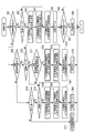
- FIG. 2 is a configuration diagram of the redundant communication system according to the embodiment.
- FIG. 3 is a block diagram of the PWM signal receiver shown in FIG.
- FIG. 4 is a flowchart showing input processing (CAN communication side) according to the embodiment.
- FIG. 5 is a flowchart showing a CAN reception abnormality determination process according to the embodiment.
- FIG. 6 is a flowchart showing input processing (PWM signal side) according to the embodiment.
- FIG. 7 is a flowchart showing a PWM signal abnormality determination process according to the embodiment.
- FIG. 1 is a configuration diagram of a fuel cell vehicle according to an embodiment of the present invention.
- FIG. 2 is a configuration diagram of the redundant communication system according to the embodiment.
- FIG. 3 is a block diagram of the PWM signal receiver shown in FIG.
- FIG. 4 is a flowchart showing input processing (CAN communication side) according to the embodiment.
- FIG. 8 is a graph showing a predetermined correspondence relationship between the duty (DUTY) of the PWM signal related to the A / P rotation speed command (PWM signal) and the A / P rotation speed command according to the embodiment.
- FIG. 9 is a flowchart showing a switching determination process according to the embodiment.
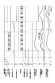
- FIG. 10 shows CANBUS data related to the A / P rotational speed command (CAN reception value), PWM signals related to the A / P rotational speed command (PWM signal), flag values of various flags, An example of a time change of a counter value, an A / P rotation speed command (CAN reception value), an A / P rotation speed command (PWM signal), and an A / P rotation speed command (APPDU control value) is shown. It is a graph.
- FIG. 11 shows CANBUS data related to the A / P rotational speed command (CAN reception value), PWM signals related to the A / P rotational speed command (PWM signal), flag values of various flags,
- An example of a time change of a counter value, an A / P rotation speed command (CAN reception value), an A / P rotation speed command (PWM signal), and an A / P rotation speed command (APPDU control value) is shown. It is a graph.
- FIG. 12 shows CANBUS data related to the A / P rotational speed command (CAN received value) according to the embodiment, PWM signal related to the A / P rotational speed command (PWM signal), flag values of various flags, An example of a time change of a counter value, an A / P rotation speed command (CAN reception value), an A / P rotation speed command (PWM signal), and an A / P rotation speed command (APPDU control value) is shown. It is a graph. FIG.
- FIG. 13 shows CANBUS data related to the A / P rotational speed command (CAN reception value), PWM signals related to the A / P rotational speed command (PWM signal), flag values of various flags,
- An example of a time change of a counter value, an A / P rotation speed command (CAN reception value), an A / P rotation speed command (PWM signal), and an A / P rotation speed command (APPDU control value) is shown. It is a graph.
- FIG. 14 shows CANBUS data related to the A / P rotational speed command (CAN received value) according to the embodiment, PWM signal related to the A / P rotational speed command (PWM signal), flag values of various flags, An example of a time change of a counter value, an A / P rotation speed command (CAN reception value), an A / P rotation speed command (PWM signal), and an A / P rotation speed command (APPDU control value) is shown. It is a graph. FIG.
- FIG. 15 shows CANBUS data related to the A / P rotational speed command (CAN reception value), PWM signals related to the A / P rotational speed command (PWM signal), flag values of various flags,
- An example of a time change of a counter value, an A / P rotation speed command (CAN reception value), an A / P rotation speed command (PWM signal), and an A / P rotation speed command (APPDU control value) is shown. It is a graph.
- FIG. 16 shows CANBUS data related to the A / P rotational speed command (CAN reception value), PWM signals related to the A / P rotational speed command (PWM signal), flag values of various flags,
- An example of a time change of a counter value, an A / P rotation speed command (CAN reception value), an A / P rotation speed command (PWM signal), and an A / P rotation speed command (APPDU control value) is shown. It is a graph.
- CANBUS data related to the A / P rotational speed command (CAN received value), PWM signals related to the A / P rotational speed command (PWM signal), flag values of various flags, and various types
- An example of a time change of a counter value, an A / P rotation speed command (CAN reception value), an A / P rotation speed command (PWM signal), and an A / P rotation speed command (APPDU control value) is shown. It is a graph.
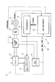
- the redundant communication system 10 is mounted on, for example, the fuel cell vehicle 1 shown in FIG.
- the fuel cell vehicle 1 includes an FC stack 12, an anode gas supply system 13, an air pump (A / P) 14, a high voltage battery 15, and a power supply device that supplies power to a motor power drive unit (MOTPDU) 11.
- a power distribution device 16 in which an FC (fuel cell) stack 12 and a high voltage battery 15 are connected in parallel is connected in parallel to a motor power drive unit (MOTPDU) 11.
- the driving force of the traveling motor 17 driven by the motor power drive unit (MOTPDU) 11 is transmitted to the drive wheels W via a speed reducer (not shown).
- the motor 17 functions as a generator to generate a so-called regenerative braking force to reduce the kinetic energy of the vehicle body. Recover as electrical energy.
- the control device 1a of the fuel cell vehicle 1 includes, for example, a motor power drive unit (MOTPDU) 11, an anode gas supply system 13, an air pump (A / P) 14, an electric power distribution device 16, and an ECU 18. It is configured. Further, the ECU 18 includes an integrated (cooperative) control ECU 21 that is a so-called server device and an air supply control ECU 22 that is a so-called client device.
- MOTPDU motor power drive unit
- a / P air pump
- ECU 18 includes an integrated (cooperative) control ECU 21 that is a so-called server device and an air supply control ECU 22 that is a so-called client device.
- the traveling motor 17 composed of a permanent magnet type three-phase AC synchronous motor is driven and controlled by three-phase AC power supplied from a motor power drive unit (MOTPDU) 11.
- the motor power drive unit (MOTPDU) 11 includes a PWM inverter composed of, for example, a transistor switching element.
- the motor power drive unit (MOTPDU) 11 converts DC power output from the power distribution device 16 into three-phase AC power and supplies it to the motor 17. .
- the FC (fuel cell) stack 12 is formed by stacking a plurality of cells formed by sandwiching a solid polymer electrolyte membrane made of, for example, a solid polymer ion exchange membrane between an anode and a cathode from both sides.
- the FC (fuel cell) stack 12 includes a fuel electrode to which an anode gas such as hydrogen gas is supplied as fuel, and an air electrode to which air containing oxygen is supplied as an oxidant. Then, hydrogen ions generated by the catalytic reaction at the anode pass through the solid polymer electrolyte membrane and move to the cathode, causing an electrochemical reaction with oxygen at the cathode to generate electricity.
- the anode gas supply system 13 supplies anode gas such as hydrogen gas to the fuel electrode of the FC (fuel cell) stack 12.
- the air pump (A / P) 14 supplies air to the air electrode of the FC (fuel cell) stack 12 based on a control command output from the air supply control ECU 22.
- the high voltage battery 15 is, for example, a lithium ion battery or a nickel metal hydride (Ni-MH) battery.
- the power distribution device 16 includes, for example, a high voltage distributor and the like, and exchange of electric power between the motor power drive unit (MOTPDU) 11 and the high voltage battery 15 based on distribution control information output from the integrated (cooperative) control ECU 21.
- the power output from the FC (fuel cell) stack 12 is distributed to the motor power drive unit (MOTPDU) 11 and the high voltage battery 15.
- the integrated (cooperative) control ECU 21 outputs a control command value (A / P rotational speed) for the rotational speed of the air pump (A / P) 14 as a control command for controlling the operation of the air supply control ECU 22.
- distribution control information for controlling the power distribution device 16 is output.
- the integrated (cooperative) control ECU 21 includes a detection signal output from a sensor (not shown) that detects a state quantity (for example, the rotation speed) of the traveling motor 17 and a state of the FC (fuel cell) stack 12.
- a detection signal output from a sensor (not shown) that detects a state quantity required for calculation) is input. Then, the integrated (cooperative) control ECU 21 calculates, for example, a control command value (A / P rotation speed) and distribution control information based on each detection signal.
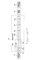
- the redundant communication system 10 includes, for example, an integrated (cooperative) control ECU 21 and an air supply control ECU 22 as shown in FIG.
- the integrated (cooperative) control ECU 21 and the air supply control ECU 22 are connected by, for example, a CAN (Controller (Area Network) communication line 61 for digital communication and a PWM signal line 62 for analog communication.
- CAN Controller (Area Network) communication line 61 for digital communication
- PWM signal line 62 for analog communication.
- the integrated (cooperative) control ECU 21 includes, for example, a control command value calculation unit 71 and a CAN driver 72 of a CAN protocol. Further, the air supply control ECU 22 switches a CAN protocol CAN driver 81, a CAN communication side input processing unit 82, a PWM signal receiving unit 83, a PWM signal side input processing unit 84, a control command value storage unit 85, A processing unit 86 and a control command value output unit 87 are provided.
- a CAN driver 72 of the integrated (cooperative) control ECU 21 and a CAN driver 81 of the air supply control ECU 22 are connected by a CAN communication line 61.
- a control command value calculation unit 71 of the integrated (cooperation) control ECU 21 and a PWM signal reception unit 83 of the air supply control ECU 22 are connected by a PWM signal line 62.
- the control command value calculation unit 71 of the integrated (cooperative) control ECU 21 uses, for example, a control command value (A / P rotation speed) for the rotation speed of the air pump (A / P) 14 as a control command value output to the air supply control ECU 22. Is calculated.
- Each control signal obtained by appropriately converting the control command value (A / P rotation speed) corresponding to each communication line 61, 62 that is, CANBUS data for the CAN communication line 61 and the PWM signal line 62).
- PWM signal is output. That is, the CANBUS data is output to the CAN driver 81 of the air supply control ECU 22 via the CAN driver 72 and the CAN communication line 61. Further, the PWM signal is output to the PWM signal receiving unit 83 of the air supply control ECU 22 via the PWM signal line 62.
- the CAN driver 81 of the air supply control ECU 22 converts CANBUS data, which is a command signal input from the integrated (cooperation) control ECU 21, into an A / P rotational speed command (CAN received value). Then, this A / P rotational speed command (CAN received value) is output to the CAN communication side input processing unit 82.
- the CAN communication side input processing unit 82 is CANBUS data related to the A / P rotation speed command (CAN reception value) input from the CAN driver 81 or the A / P rotation speed command (CAN reception value) via the CAN communication line 61.
- the PWM signal receiving unit 83 converts a PWM signal, which is a command signal input from the integrated (cooperative) control ECU 21, into an A / P rotation speed command (PWM signal), and converts the A / P rotation speed command (PWM signal) to PWM.
- PWM signal is a command signal input from the integrated (cooperative) control ECU 21, into an A / P rotation speed command (PWM signal), and converts the A / P rotation speed command (PWM signal) to PWM.
- the signal is output to the signal side input processing unit 84.
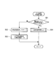
- the PWM signal receiving unit 83 is provided between the control command value calculating unit 71 and the PWM signal side input processing unit 84, for example, as shown in FIG.
- the PWM signal receiving unit 83 includes a noise filter unit 83a including a common mode filter 83b and a transistor 83c, a photocoupler 83d, a Schmitt trigger 83e, a low-pass filter 83f, and a buffer amplifier 83g.
- the common mode filter 83b, transistor 83c, photocoupler 83d, Schmitt trigger 83e, low pass filter 83f, and buffer amplifier 83g are sequentially provided. And are arranged. That is, the PWM signal transmitted from the control command value calculation unit 71 sequentially passes through the common mode filter 83b, the transistor 83c, the photocoupler 83d, the Schmitt trigger 83e, the low pass filter 83f, and the buffer amplifier 83g.
- the PWM signal side input processing unit 84 and the switching processing unit 86 are transmitted.
- the noise filter unit 83a may include only one of the common mode filter 83b and the transistor 83c. However, the noise can be further reduced by including the common mode filter 83b and the transistor 83c. can do.
- the photocoupler 83d as a boundary.
- the cooperative control ECU 21 including the control command value calculation unit 71, the common mode filter 83b, the transistor 83c, and the like belong to the low voltage region.
- the Schmitt trigger 83e, the low-pass filter 83f, the buffer amplifier 83g, the PWM signal side input processing unit 84, the switching processing unit 86, and the like belong to the high voltage region.
- the voltage of the PWM signal is a low voltage in the common mode filter 83b and the transistor 83c, but is a high voltage in the Schmitt trigger 83e, the low-pass filter 83f, the buffer amplifier 83g, and the like.
- the voltage in the low voltage region is the voltage of the control power supply
- the voltage in the high voltage region is the voltage of the fuel cell.
- the PWM signal receiving unit 83 performs the following signal processing.
- the PWM signal is transmitted from the control command value calculation unit 71, first, common mode noise included in the PWM signal is reduced by the common mode filter 83b.
- normal mode noise included in the PWM signal is reduced by the transistor 83c.
- the PWM signal in which the common mode noise and the normal mode noise are reduced is optically transmitted in a state of being electrically insulated by the photocoupler 83d. Since the photocoupler 83d has a configuration in which noise is not easily transmitted, the normal mode noise included in the PWM signal is further reduced in the photocoupler 83d.
- the PWM signal transmitted from the photocoupler 83d passes through the Schmitt trigger 83e, and is adjusted to a more accurate and appropriate signal (a state in which the so-called “rounding” is reduced). Thereafter, the PWM signal is converted from a rectangular wave (pulse-shaped) signal into a continuous signal by the low-pass filter 83f. Specifically, the voltage output from the low-pass filter 83f is converted to be higher as the pulse width of the PWM signal input to the low-pass filter 83f is larger.
- the signal output from the low pass filter 83f is amplified by the buffer amplifier 83e. That is, as the output impedance (resistance) is reduced in the buffer amplifier 83e, the signal current increases.
- the PWM signal side input processing unit 84 is a duty (DUTY: that is, a motor (14) of the air pump (A / P) 14 related to the A / P rotation speed command (PWM signal) input from the PWM signal receiving unit 83. (Not shown) via a PWM signal line 62 according to the ratio of the on / off state when the switching element provided in the driver (not shown) driven by pulse width modulation by the PWM signal is driven on / off) Flag values of various flags such as a PWM signal abnormality occurrence flag indicating that an abnormality has occurred in reception of the PWM signal related to the A / P rotation speed command (PWM signal) and a PWM signal abnormality flag indicating an abnormality in the PWM signal line 62 Set.
- a PWM signal abnormality occurrence flag indicating that an abnormality has occurred in reception of the PWM signal related to the A / P rotation speed command (PWM signal)
- PWM signal abnormality flag indicating an abnormality in the PWM signal line 62 Set.
- the A / P rotation speed command (PWM signal) corresponding to the PWM signal is appropriately changed from a current value to a past value, a predetermined value (zero, etc.), for example, as necessary. Then, the A / P rotational speed command (PWM signal) is output to the control command value storage unit 85 and the switching processing unit 86, and the PWM signal abnormality flag is output to the switching processing unit 86.
- the control command value storage unit 85 includes an A / P rotational speed command (CAN reception value) input from the CAN communication side input processing unit 82 and an A / P rotational speed command (PWM) input from the PWM signal side input processing unit 84. Time-series data over a predetermined past period is stored among the difference data from the signal.
- a / P rotational speed command CAN reception value
- PWM A / P rotational speed command
- the switching processing unit 86 is connected to the CAN communication side input processing unit 82 and the PWM signal side input processing unit 84 according to the flag values of various flags.
- a command (CAN received value) or an A / P rotation speed command (PWM signal) input from the PWM signal side input processing unit 84 is selected and output to the control command value output unit 87.
- the control command value output unit 87 receives the A / P rotational speed command (CAN received value) input from the switching processing unit 86 or the A / P rotational speed command (PWM signal) input from the PWM signal side input processing unit 84.
- time-series data for example, past predetermined data
- the correction coefficient is set based on the numerical data.
- the control command value output unit 87 then applies the correction coefficient to the A / P rotation speed command (CAN reception value) or the A / P rotation speed command (PWM signal) to obtain an A / P rotation speed command (APPDU).
- the control value is output to a driver (for example, a PWM inverter) that drives a motor (not shown) of the air pump (A / P) 14 by a PWM signal.
- the redundant communication system 10 has the above configuration. Next, the operation of the redundant communication system 10 will be described with reference to the attached drawings. Note that the following input process (CAN communication side), input process (PWM signal side), and switching process are repeatedly executed in a predetermined cycle independently of each other.
- step S01 it is determined whether or not a predetermined time has elapsed since the power-on at which the energization of the control device 1a is started, such as when the fuel cell vehicle 1 is started. If this determination is “YES”, the flow proceeds to step S 04 described later. On the other hand, if this determination is “NO”, the flow proceeds to step S 02. In step S02, the flag value of the CAN reception abnormality flag indicating abnormality of the CAN communication line 61 is initialized by setting “0”, and the process proceeds to step S03.
- step S03 the A / P rotational speed command (CAN received value) is initialized by setting it to zero, and the series of processes is terminated.
- step S04 a CAN reception abnormality determination process, which will be described later, is executed, and the series of processes ends.
- step S11 it is determined whether a reception abnormality is detected using a ring counter, a checksum, or the like. If this determination is “YES”, the flow proceeds to step S 15 described later. On the other hand, if this determination is “NO”, the flow proceeds to step S 12.
- step S12 the flag value of the CAN reception abnormality occurrence flag indicating that an abnormality has occurred in reception of CANBUS data related to the A / P rotation speed command (CAN reception value) via the CAN communication line 61 is set to “0”. Is set, and the process proceeds to step S13.
- step S13 the current value of the A / P rotational speed command (CAN received value) based on the CANBUS data received from the integrated (cooperative) control ECU 21 via the CAN communication line 61 in the current process is newly set to A. / P rotational speed command (CAN received value) is set, and the process proceeds to step S14.
- step S14 “0” is set to the flag value of the CAN reception abnormality flag indicating abnormality of the CAN communication line 61, and the series of processing ends.
- step S15 “1” is set in the flag value of the CAN reception abnormality occurrence flag, and the process proceeds to step S16. Then, in step S16, it is determined whether or not a predetermined time has elapsed as a time period for which the abnormality that has occurred has occurred since the reception abnormality has occurred. If this determination is “YES”, the flow proceeds to step S 19 described later. On the other hand, if this determination is “NO”, the flow proceeds to step S 17. In step S17, the previous value of the A / P rotational speed command (CAN received value) based on the CANBUS data received from the integrated (cooperative) control ECU 21 via the CAN communication line 61 in the previous process is newly set to A.
- step S17 the previous value of the A / P rotational speed command (CAN received value) based on the CANBUS data received from the integrated (cooperative) control ECU 21 via the CAN communication line 61 in the previous process is newly set to A.
- step S18 “1” is set to the flag value of the CAN determination flag indicating that the process for determining whether or not the CAN communication line 61 is abnormal is being executed, and the series of processes is terminated.
- step S19 zero is set in the A / P rotation speed command (CAN reception value), and the process proceeds to step S20.
- the flag value of the CAN reception abnormality flag is set to “1”, and the series of processes ends.
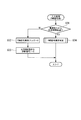
- step S31 shown in FIG. 6 it is determined whether or not a predetermined time has elapsed since the power-on at which energization to the control device 1a is started, such as when the fuel cell vehicle 1 is started. If this determination is “YES”, the flow proceeds to step S 34 described later. On the other hand, if this determination is “NO”, the flow proceeds to step S 32. In step S32, the flag value of the PWM signal abnormality flag indicating abnormality of the PWM signal line 62 is set to "0" for initialization, and the process proceeds to step S33.
- step S33 the A / P rotational speed command (PWM signal) is set to zero and initialized, and a series of processes is terminated.
- step S34 a PWM signal abnormality determination process to be described later is executed, and the series of processes is terminated.
- step S41 by determining whether or not the duty (DUTY) of the PWM signal related to the A / P rotation speed command (PWM signal) is less than a predetermined lower limit value, the disconnection abnormality is detected. Whether or not has occurred is determined. If this determination is “YES”, the flow proceeds to step S 46 described later. On the other hand, if this determination is “NO”, the flow proceeds to step S 42.
- step S42 for example, by determining whether or not the duty (DUTY) of the PWM signal related to the A / P rotation speed command (PWM signal) is larger than a predetermined upper limit value, a short circuit abnormality has occurred. It is determined whether or not. If this determination is “YES”, the flow proceeds to step S 46 described later. On the other hand, if this determination is “NO”, the flow proceeds to step S 43.
- step S43 the flag value of the PWM signal abnormality occurrence flag indicating that an abnormality has occurred in reception of the PWM signal related to the A / P rotation speed command (PWM signal) via the PWM signal line 62 is set to “0”. Is set, and the process proceeds to step S44.
- step S44 a new A / P rotational speed command (PWM signal) is obtained, for example, by searching a map for a predetermined map corresponding to the duty (DUTY) of the PWM signal related to the A / P rotational speed command (PWM signal). Is acquired and it progresses to step S45.
- the predetermined map is a map showing a predetermined correspondence relationship between the duty (DUTY) and the A / P rotation speed command as shown in FIG.
- the duty (DUTY) has a predetermined lower limit DL.
- the A / P rotational speed command is zero.
- the duty (DUTY) increases from the predetermined value (DL + ⁇ ) to the predetermined value (DH ⁇ )
- the A / P rotational speed command changes to a predetermined upper limit rotational speed command NH.
- the duty (DUTY) is in a range from a predetermined value (DH- ⁇ ) to a predetermined upper limit value DH
- the A / P rotation speed command is set to the upper limit rotation speed command NH.
- “0” is set to the flag value of the PWM signal abnormality flag indicating the abnormality of the PWM signal line 62, and the series of processing ends.
- step S46 “1” is set to the flag value of the PWM signal abnormality occurrence flag. Then, in step S47, it is determined whether or not a predetermined time has elapsed as a time during which the abnormality that has occurred has occurred since the occurrence of a disconnection abnormality or a short-circuit abnormality. If this determination is “YES”, the flow proceeds to step S 49 described later. On the other hand, if this determination is “NO”, the flow proceeds to step S 48.
- step S48 the previous value of the A / P rotational speed command (PWM signal) based on the PWM signal received from the integrated (cooperative) control ECU 21 via the PWM signal line 62 in the previous process is newly set to A / A P rotation speed command (PWM signal) is set, and a series of processing ends.
- step S49 zero is set in the A / P rotation speed command (CAN reception value), and the process proceeds to step S50.
- step S50 “1” is set to the flag value of the PWM signal abnormality flag, and the series of processing ends.
- step S61 it is determined whether or not the flag value of the CAN reception abnormality occurrence flag is “0”. If this determination is “NO”, the flow proceeds to step S 69 described later. On the other hand, if this determination is “YES”, the flow proceeds to step S62.
- step S62 the switching processor 86 sets the flag value of the switching flag indicating that the A / P rotational speed command (CAN received value) is switched to the A / P rotational speed command (PWM signal). It is determined whether or not “1”. If this determination is “NO”, the flow proceeds to step S 65 described later. On the other hand, if this determination is “YES”, the flow proceeds to step S63.
- a correction coefficient for the A / P rotational speed command (CAN received value) is set, and the process proceeds to step S64.
- the correction coefficient is, for example, the difference between the A / P rotational speed command (CAN reception value) and the A / P rotational speed command (PWM signal) stored in the control command value storage unit 85 immediately before the current process. It is set according to the data. For example, the correction coefficient is calculated based on an A / P rotational speed command (CAN reception value) and an A / P rotational speed command (PWM signal) at a plurality of predetermined rotational speeds with respect to the rotational speed of the air pump (A / P) 14. The difference average value based on the difference of
- step S64 the correction coefficient for the A / P rotational speed command (PWM signal) is initialized to zero, and the process proceeds to step S65.
- step S65 the A / P rotational speed command (CAN received value) after correction by the correction coefficient is set as the A / P rotational speed command, and the process proceeds to step S66.
- step S66 “0” is set to the flag value of the switching flag, and the process proceeds to step S67.
- step S67 it is determined whether or not the flag value of the PWM signal abnormality occurrence flag is “0”. When the determination result is “NO”, the series of processes is terminated. On the other hand, if this determination is “YES”, the flow proceeds to step S68.
- step S68 as a learning process, the difference between the current value of the A / P rotational speed command (CAN reception value) and the current value of the A / P rotational speed command (PWM signal) is stored in the control command value storage unit 85. Store, and the series of processing ends.
- step S69 it is determined whether or not the flag value of the PWM signal abnormality occurrence flag is “0”. If this determination is “NO”, the flow proceeds to step S 76 described later. On the other hand, if this determination is “YES”, the flow proceeds to step S70.
- step S70 it is determined whether or not the flag value of the switching flag is “0”. If this determination is “NO”, the flow proceeds to step S 74 described later. On the other hand, if this determination is “YES”, the flow proceeds to step S71.
- step S71 it is determined whether or not a predetermined standby time has elapsed since the occurrence of CAN reception abnormality. If the determination result is “NO”, the determination process of step S71 is repeated. On the other hand, if this determination is “YES”, the flow proceeds to step S72.
- a correction coefficient for the A / P rotational speed command (PWM signal) is set, and the process proceeds to step S73.
- the correction coefficient is, for example, the difference between the A / P rotational speed command (CAN reception value) and the A / P rotational speed command (PWM signal) stored in the control command value storage unit 85 immediately before the current process. It is set according to the data. For example, the correction coefficient is calculated based on an A / P rotational speed command (CAN reception value) and an A / P rotational speed command (PWM signal) at a plurality of predetermined rotational speeds with respect to the rotational speed of the air pump (A / P) 14. The difference average value based on the difference of
- step S73 the correction coefficient for the A / P rotational speed command (CAN received value) is initialized to zero, and the process proceeds to step S74.
- step S74 the A / P rotation speed command (PWM signal) corrected by the correction coefficient is set as the A / P rotation speed command, and the process proceeds to step S75.
- step S75 “1” is set to the flag value of the switching flag, and the series of processing ends.
- step S76 it is determined whether or not the flag value of the CAN determination flag is “1”. If this determination is “NO”, the flow proceeds to step S 77, where zero is set as the A / P rotation speed command, and the series of processes is terminated. On the other hand, if this determination is “YES”, the flow proceeds to step S78.
- step S78 it is determined whether or not the flag value of the switching flag is “1”. If this determination is “NO”, the flow proceeds to step S 81 described later. On the other hand, if the determination is “YES”, the flow proceeds to step S79.
- step S79 a correction coefficient for the A / P rotational speed command (CAN received value) is set, and the process proceeds to step S80.
- the correction coefficient is, for example, the difference between the A / P rotational speed command (CAN reception value) and the A / P rotational speed command (PWM signal) stored in the control command value storage unit 85 immediately before the current process. It is set according to the data.
- the correction coefficient is calculated based on an A / P rotational speed command (CAN reception value) and an A / P rotational speed command (PWM signal) at a plurality of predetermined rotational speeds with respect to the rotational speed of the air pump (A / P) 14.
- the difference average value based on the difference of
- step S80 the correction coefficient for the A / P rotational speed command (PWM signal) is initialized to zero, and the process proceeds to step S81.
- step S81 the A / P rotational speed command (CAN received value) after correction using the correction coefficient is set as the A / P rotational speed command, and the process proceeds to step S82.
- step S82 the flag value of the switching flag is set to “0”, and the series of processes is terminated.
- the flag value of the substrate power supply (low pressure system) flag is changed from “0” to “1” when power is supplied to the control device 1 a when the fuel cell vehicle 1 is started.
- the timing switched to is time t0, and the period from time t0 to time t1 when a predetermined time elapses is called a preparation period.
- the flag values of the CAN reception abnormality flag and the PWM signal abnormality flag are set to “0”. Also, zero is set in the A / P rotational speed command (CAN reception value) and the A / P rotational speed command (PWM signal).
- the timing at which each counter value of the abnormality detection counter indicating the elapsed time of reception abnormality and the disconnection abnormality counter indicating the elapsed time of disconnection abnormality is less than the predetermined standby time is defined as time t2.
- the A / P rotation speed command (CAN reception value) and the A / P rotation speed command (PWM signal) change from zero to an increasing tendency with the generation of the CANBUS data and the PWM signal.
- the switching processing unit After this time t2, when each flag value of the CAN reception abnormality flag and the PWM signal abnormality flag is “0” and no abnormality has occurred in the CAN communication line 61 and the PWM signal line 62, the switching processing unit At 86, an A / P rotational speed command (CAN received value) is selected, and this A / P rotational speed command (CAN received value) is set as an A / P rotational speed command (APPDU control value).
- the counter value of the abnormality detection counter is less than a predetermined standby time, and the A / P rotation speed command (CAN reception value) tends to increase from zero with the generation of CANBUS data.
- the timing of changing to is time t2.
- time t2 when the flag value of the CAN reception abnormality flag is “0” and no abnormality has occurred in the CAN communication line 61, for example, time t3 when the counter value of the disconnection abnormality counter is a predetermined time. Is reached, the flag value of the PWM signal abnormality flag becomes “1” after time t3, and it is determined that an abnormality has occurred in the PWM signal line 62.
- the switching processor 86 selects the A / P rotational speed command (CAN reception value), and this A / P rotational speed command (CAN reception). Value) is set as the A / P rotational speed command (APPDU control value).
- the timing at which the A / P rotation speed command (CAN reception value) is selected in the switching processor 86 is time t2, and after this time t2, the CAN communication line 61 and the PWM signal line 62
- the timing at which the counter value of the disconnection abnormality counter changes in an increasing tendency with no abnormality occurring at time t4 is at time t4.
- the value immediately before (that is, the previous value) is maintained.
- the flag value of the PWM signal abnormality flag becomes “1” after time t5, and an abnormality occurs in the PWM signal line 62. If it is determined that the A / P rotational speed command (PWM signal) is zero, zero is set.
- the count value of the disconnection abnormality counter is less than a predetermined standby time, and the A / P rotational speed command (PWM signal) changes from zero to an increasing tendency as the PWM signal is generated.
- the timing is time t2, and after this time t2, the flag value of the PWM signal abnormality flag is “0” and no abnormality has occurred in the PWM signal line 62.
- the switching processor 86 selects the A / P rotational speed command (PWM signal), and this A / P rotational speed command (PWM signal). ) Is set as the A / P rotational speed command (APPDU control value).
- the A / P rotation speed command (CAN reception value) is selected in the switching processing unit 86 when there is no abnormality in the CAN communication line 61 and the PWM signal line 62.
- the timing is set to time t2, and after this time t2, for example, the timing at which the counter value of the abnormality detection counter changes in an increasing tendency is set to time t7.
- the A / P rotational speed command (CAN received value) is issued. The value immediately before time t7 (that is, the previous value) is maintained.
- the A / P rotational speed command (APPDU control value) is maintained at the value immediately before time t7 (that is, the previous value) in the same manner as the A / P rotational speed command (CAN received value). For example, if the timing at which the counter value of the abnormality detection counter reaches the predetermined standby time is a state in which the counter value of the abnormality detection counter continues to increase after time t8, the flag value of the CAN reception abnormality flag is set. Even if “0”, the switching processing unit 86 switches and selects the A / P rotational speed command (CAN received value) from the A / P rotational speed command (PWM signal), and the A / P rotational speed command (PWM).
- a / P rotational speed command (APPDU control value). For example, when the counter value of the abnormality detection counter reaches a predetermined time, the flag value of the CAN reception abnormality flag becomes “1” as after time t9, and it is determined that an abnormality has occurred in the CAN communication line 61. Then, zero is set in the A / P rotational speed command (CAN reception value).
- an A / P rotational speed command (CAN reception value) is selected in the switching processing unit 86 in accordance with the fact that no abnormality has occurred in the CAN communication line 61 and the PWM signal line 62.
- the timing is set to time t2, and after this time t2, for example, the timing at which the counter value of the abnormality detection counter changes in an increasing tendency is set to time t7.
- the A / P rotational speed command (CAN received value) is issued.
- the value immediately before time t7 that is, the previous value) is maintained.
- the A / P rotational speed command (APPDU control value) is maintained at the value immediately before time t7 (that is, the previous value) in the same manner as the A / P rotational speed command (CAN received value). For example, if the counter value of the abnormality detection counter continues to increase after time t8 when the counter value of the abnormality detection counter reaches the predetermined standby time, the flag value of the CAN reception abnormality flag is “0”. , The switching processor 86 selects the A / P rotational speed command (CAN received value) to the A / P rotational speed command (PWM signal), and the A / P rotational speed command (PWM signal). Is set as the A / P rotational speed command (APPDU control value).
- the A / P rotational speed command (PWM signal) set as the A / P rotational speed command (APPDU control value) is the A / P rotational speed command (CAN received value) stored in the control command value storage unit 85. ) And the A / P rotational speed command (PWM signal). Then, at time t8 when the A / P rotational speed command (APPDU control value) is switched from the A / P rotational speed command (CAN received value) to the A / P rotational speed command (PWM signal), the A / P rotational speed is selected.
- the numerical command (APPDU control value) is set so that smooth switching is performed so that it does not fluctuate rapidly.
- the timing at which the counter values of the abnormality detection counter and the disconnection abnormality counter reach a predetermined time is defined as time t10.
- the flag values of the CAN reception abnormality flag and the PWM signal abnormality flag become “1”, and it is determined that an abnormality has occurred in the CAN communication line 61 and the PWM signal line 62.
- a / P rotational speed command (CAN reception value) and the A / P rotational speed command (PWM signal) become zero, zero is set as the A / P rotational speed command (APPDU control value).
- the A / P rotation speed command (CAN reception value) is selected in the switching processing unit 86 because no abnormality has occurred in the CAN communication line 61 and the PWM signal line 62.
- the timing is set to time t2, and after this time t2, for example, after time t11 when the counter value of the abnormality detection counter changes in an increasing tendency, the A / P rotation speed command (CAN reception value) is a value immediately before time t11 ( That is, the previous value is maintained. Accordingly, the A / P rotational speed command (APPDU control value) is maintained at the value immediately before time t11 (that is, the previous value), similarly to the A / P rotational speed command (CAN received value).
- the timing to perform is set to time t12, and after this time t12, the switching processing unit 86 switches and selects the A / P rotational speed command (CAN received value) to the A / P rotational speed command (PWM signal).
- a rotational speed command (PWM signal) is set as an A / P rotational speed command (APPDU control value).
- the flag value of the CAN reception abnormality flag becomes “1” after time t13, and it is determined that an abnormality has occurred in the CAN communication line 61. Then, zero is set in the A / P rotational speed command (CAN reception value). Further, for example, after time t14 when the counter value of the disconnection abnormality counter changes in an increasing tendency, the A / P rotational speed command (PWM signal) is maintained at the value immediately before time t14 (that is, the previous value).
- the A / P rotational speed command (APPDU control value) is maintained at the value immediately before time t14 (that is, the previous value), similarly to the A / P rotational speed command (PWM signal). Then, for example, when the count value of the disconnection abnormality counter reaches a predetermined time, the flag value of the PWM signal abnormality flag becomes “1” after time t15, and it is determined that an abnormality has occurred in the PWM signal line 62. Then, zero is set in the A / P rotational speed command (PWM signal). Along with this, zero is set as the A / P rotation speed command (APPDU control value).
- CAN indicating that an abnormality has occurred in reception of CANBUS data related to the A / P rotation speed command (CAN reception value) via the CAN communication line 61.
- the A / P rotational speed command (APPDU control value) is changed from the A / P rotational speed command (CAN received value) to the A / P rotational speed command (PWM signal).
- the air pump (A / P) 14 is appropriately controlled by the control command value calculated by the integrated (cooperative) control ECU 21. can do.
- the A / P rotational speed command (APPDU control value) is changed from the A / P rotational speed command (CAN received value) to A / P. Even after switching to the rotational speed command (PWM signal), the flag value of the CAN reception abnormality occurrence flag is switched from “1” to “0”, and the reception abnormality is resolved. Accordingly, the possibility that the CAN communication line 61 is determined to be abnormal disappears.
- the PWM signal line The accuracy of controlling the air pump (A / P) 14 can be improved by the CAN communication line 61 having a communication capacity, a communication speed and the like superior to those of the 62.
- the flag value of the CAN reception abnormality occurrence flag is changed from “0” to “1”.
- the A / P rotational speed command (CAN reception value) is the value immediately before this time (that is, the previous time) Value).
- an abnormality may occur during a period until the A / P rotation speed command (APPDU control value) is switched from the A / P rotation speed command (CAN reception value) to the A / P rotation speed command (PWM signal).
- Appropriate control of the air pump (A / P) 14 can be continued without using a control command value having a characteristic.
- the A / P rotational speed command (CAN received value) and the A / P rotational speed command (PWM signal) are corrected to be equal.
- the A / P rotation speed command (APPDU control value) is smoothly changed before and after the selection of switching between the A / P rotation speed command (CAN reception value) and the A / P rotation speed command (PWM signal). It is possible to prevent the control state of the air pump (A / P) 14 from changing rapidly.
- the integration (cooperation) control ECU 21 and the air supply control ECU 22 are connected by the CAN communication line 61 and the PWM signal line 62 with different communication modes, for example, they are integrated (cooperation) with the communication lines with the same communication mode.
- the air pump (A / P) 14 is appropriately adjusted while improving the complementarity to the communication between the integrated (cooperation) control ECU 21 and the air supply control ECU 22. Can be controlled.
- the PWM signal receiving unit 83 is sequentially transmitted via the noise filter unit 83a, the Schmitt trigger 83e, and the low-pass filter 83f, so that noise is generated.
- the reduced and accurate PWM signal can be input to the low-pass filter 83f. Therefore, the low-pass filter 83f can appropriately convert and output the PWM signal.
- control of the air pump (A / P) 14 based on a PWM signal can be performed appropriately.
- both the common mode filter 83b and the transistor 83c in the noise filter unit 83a both common mode noise and normal mode noise can be accurately suppressed, and a highly accurate PWM signal can be transmitted. it can.
- the photocoupler 83d by providing the photocoupler 83d, the voltage of the PWM signal can be accurately converted, and noise can be further reduced. Further, by providing the transistor 83c on the input side of the photocoupler 83d, failure of the photocoupler 83d can be prevented. For example, when the transistor 83c is not provided, when a relatively large noise is input, the photocoupler 83d may break down and the PWM signal may not be transmitted. However, the provision of the transistor 83c can prevent such a problem from occurring. Therefore, the PWM signal can be transmitted more accurately to the PWM signal side input processing unit 84, and the occurrence of abnormality in the PWM signal can be prevented.
- the common mode filter 83b, the transistor 83c, the photocoupler 83d, and the Schmitt trigger 83e are sequentially arranged from the control command value calculation unit 71 side to the PWM signal side input processing unit 84 side.
- the low-pass filter 83f and the buffer amplifier 83g are arranged, the present invention is not limited to this.
- the order from the input side of the PWM signal of the common mode filter 83b and the transistor 83c may be switched.
- the photocoupler 83d may be provided on the output side of the buffer amplifier 83e (that is, between the buffer amplifier 83e and the PWM signal side input processing unit 84) instead of between the noise filter unit 83a and the Schmitt trigger 83e. Good.
- the redundant communication system 10 is mounted on the fuel cell vehicle 1, but is not limited thereto, and may be mounted on other vehicles such as a hybrid vehicle.
- the redundant communication system 10 includes the integrated (cooperative) control ECU 21 and the air supply control ECU 22, but is not limited thereto.
- the air supply control ECU 22 another control ECU may be provided, and the control command value for other power devices is switched and selected, not limited to the motor that drives the air pump (A / P) 14. May be.
- the redundant communication system of the present invention it is possible to optimize the control of the power equipment mounted on the vehicle even when an abnormality occurs in the vehicle communication system.
Landscapes
- Engineering & Computer Science (AREA)
- Computer Networks & Wireless Communication (AREA)
- Signal Processing (AREA)
- Health & Medical Sciences (AREA)
- Computing Systems (AREA)
- General Health & Medical Sciences (AREA)
- Medical Informatics (AREA)
- Electric Propulsion And Braking For Vehicles (AREA)
Abstract
Description
本願は、2007年12月26日に日本出願された特願2007-334101号に基づき優先権を主張し、その内容を取り込むものとする。 The present invention relates to a redundant communication system.
This application claims priority based on Japanese Patent Application No. 2007-334101 filed in Japan on December 26, 2007, and incorporates the contents thereof.
本発明は上記事情に鑑みてなされたもので、車両の通信システムに異常が発生した場合であっても、車両に搭載された電力機器の制御を適正化することが可能な冗長通信システムを提供することを目的とする。 By the way, in the motor control device according to an example of the above-described prior art, it is desired to improve the determination accuracy of whether or not an abnormality has occurred in the serial communication line and improve the reliability of the determination result. Further, it is desired to optimize the drive control of the motor by controlling the execution timing of the determination process and the timing of switching the communication line in more detail.
The present invention has been made in view of the above circumstances, and provides a redundant communication system capable of optimizing the control of power equipment mounted on a vehicle even when an abnormality occurs in the communication system of the vehicle. The purpose is to do.
しかも、フォトカプラの入力側にトランジスタを設けることにより、フォトカプラの故障を防止することができる。すなわち、例えばトランジスタを備えていない場合には、相対的に大きなノイズが入力されたときに、フォトカプラが故障して、PWM信号を伝達することができなくなる虞が生じるが、トランジスタを設けることにより、このような不具合の発生を防止することができる。従って、PWM信号をより的確に送信することができ、PWM信号の異常発生を防止することが可能となる。 Furthermore, by providing a photocoupler, the voltage of the PWM signal can be accurately converted, and noise can be further reduced.
In addition, failure of the photocoupler can be prevented by providing a transistor on the input side of the photocoupler. That is, for example, when a transistor is not provided, when a relatively large noise is input, there is a possibility that the photocoupler breaks down and the PWM signal cannot be transmitted. The occurrence of such problems can be prevented. Therefore, the PWM signal can be transmitted more accurately, and the occurrence of abnormality in the PWM signal can be prevented.
1a 制御装置
10 冗長通信システム
11 モータパワードライブユニット(MOTPDU)
12 FCスタック
13 アノードガス供給システム
14 エアーポンプ(A/P)(電力機器)
15 高圧バッテリ
16 電力分配装置
17 モータ
21 統合(協調)制御ECU(第1制御装置)
22 空気供給制御ECU(第2制御装置)
61 CAN通信ライン(主通信線)
62 PWM信号ライン(副通信線)
82 CAN通信側入力処理部(主通信線異常判定手段)
83a ノイズフィルタ部
83b コモンモードフィルタ
83c トランジスタ
83d フォトカプラ
83e シュミットトリガ
83f ローパスフィルタ
83g バッファアンプ
85 制御指令値記憶部(記憶手段)
86 切換処理部(制御指令値切換手段)
87 制御指令値出力部(補正手段) 1 Fuel cell vehicle (vehicle)
DESCRIPTION OF
12
DESCRIPTION OF
22 Air supply control ECU (second control device)
61 CAN communication line (main communication line)
62 PWM signal line (sub communication line)
82 CAN communication side input processing unit (main communication line abnormality determination means)
83a
86 Switching processor (control command value switching means)
87 Control command value output section (correction means)
さらに、ECU18は、いわゆるサーバ装置である統合(協調)制御ECU21と、いわゆるクライアント装置である空気供給制御ECU22とを備えて構成されている。 The
Further, the
モータパワードライブユニット(MOTPDU)11は、例えばトランジスタのスイッチング素子から構成されたPWMインバータを備えており、電力分配装置16から出力される直流電力を3相交流電力に変換して、モータ17へ供給する。 The traveling
The motor power drive unit (MOTPDU) 11 includes a PWM inverter composed of, for example, a transistor switching element. The motor power drive unit (MOTPDU) 11 converts DC power output from the
エアーポンプ(A/P)14は、空気供給制御ECU22から出力される制御指令に基づいて、FC(燃料電池)スタック12の空気極に空気を供給する。 The anode
The air pump (A / P) 14 supplies air to the air electrode of the FC (fuel cell) stack 12 based on a control command output from the air
電力分配装置16は、例えば高圧分配器等を備え、統合(協調)制御ECU21から出力される分配制御情報に基づいて、モータパワードライブユニット(MOTPDU)11と高圧バッテリ15との間の電力のやり取りと、FC(燃料電池)スタック12から出力される電力のモータパワードライブユニット(MOTPDU)11および高圧バッテリ15への分配とを制御する。 The
The
この統合(協調)制御ECU21には、走行用のモータ17の状態量(例えば、回転数等)を検出するセンサ(図示略)から出力される検出信号と、FC(燃料電池)スタック12の状態量(例えば、電流、電圧、温度等)を検出するセンサ(図示略)から出力される検出信号と、高圧バッテリ15の状態量(例えば、電流、電圧、温度等であって、残容量SOCの算出に必要とされる状態量)を検出するセンサ(図示略)から出力される検出信号とが入力されている。そして、統合(協調)制御ECU21は、各検出信号に基づき、例えば制御指令値(A/P回転数)および分配制御情報を算出する。 In the
The integrated (cooperative)
また、空気供給制御ECU22は、CANプロトコルのCANドライバ81と、CAN通信側入力処理部82と、PWM信号受信部83と、PWM信号側入力処理部84と、制御指令値記憶部85と、切換処理部86と、制御指令値出力部87とを備えて構成されている。
統合(協調)制御ECU21のCANドライバ72と空気供給制御ECU22のCANドライバ81とがCAN通信ライン61により接続されている。統合(協調)制御ECU21の制御指令値算出部71と空気供給制御ECU22のPWM信号受信部83とがPWM信号ライン62により接続されている。 The integrated (cooperative)
Further, the air
A
CAN通信側入力処理部82は、CANドライバ81から入力されたA/P回転数指令(CAN受信値)に係るCANBUSデータあるいはCAN通信ライン61を介したA/P回転数指令(CAN受信値)に係るCANBUSデータの受信状態および未受信状態等に応じて、CAN通信ライン61を介したA/P回転数指令(CAN受信値)に係るCANBUSデータの受信に異常が発生したことを示すCAN受信異常発生フラグやCAN通信ライン61の異常を示すCAN受信異常フラグ等の各種のフラグのフラグ値を設定する。また、CAN通信側入力処理部82は、CANBUSデータに応じたA/P回転数指令(CAN受信値)を、必要に応じて、例えば現在値から過去値や所定値等に適宜に変更する。そして、A/P回転数指令(CAN受信値)を制御指令値記憶部85および切換処理部86へ出力すると共に、CAN受信異常フラグを切換処理部86へ出力する。 The
The CAN communication side
なお、ノイズフィルタ部83aは、コモンモードフィルタ83bとトランジスタ83cとのいずれか一方のみを備えるようにしてもよいが、コモンモードフィルタ83bとトランジスタ83cとを備えることにより、ノイズを、より一層、低減することができる。 From the control command
The
制御指令値算出部71を具備する協調制御ECU21と、コモンモードフィルタ83bと、トランジスタ83c等とは、ローボルテージ領域に属している。一方、シュミットトリガ83eと、ローパスフィルタ83fと、バッファアンプ83gと、PWM信号側入力処理部84と、切換処理部86等とは、ハイボルテージ領域に属している。つまり、PWM信号の電圧は、コモンモードフィルタ83bおよびトランジスタ83cにおいては低い電圧であるが、シュミットトリガ83eおよびローパスフィルタ83fおよびバッファアンプ83g等においては高い電圧である。
なお、ローボルテージ領域の電圧は、制御電源の電圧であり、ハイボルテージ領域の電圧は、燃料電池の電圧である。 Further, in this embodiment, there are a low voltage region where the voltage is set lower and a high voltage region where the voltage is set higher than the low voltage region, with the
The
The voltage in the low voltage region is the voltage of the control power supply, and the voltage in the high voltage region is the voltage of the fuel cell.
制御指令値算出部71からPWM信号が送信されると、先ず、コモンモードフィルタ83bによって、PWM信号に含まれているコモンモードノイズが低減される。
次に、トランジスタ83cによって、PWM信号に含まれているノーマルモードノイズが低減される。こうしてコモンモードノイズとノーマルモードノイズとが低減されたPWM信号が、フォトカプラ83dにおいて電気的に絶縁された状態で、光学的に伝達される。なお、フォトカプラ83dはノイズが伝達されにくい構成となっているため、フォトカプラ83dにおいても、PWM信号に含まれているノーマルモードノイズが更に低減される。 The PWM
When the PWM signal is transmitted from the control command
Next, normal mode noise included in the PWM signal is reduced by the
この後、PWM信号はローパスフィルタ83fによって、矩形波状(パルス状)の信号から連続的な信号に変換される。具体的には、例えばローパスフィルタ83fに入力されたPWM信号のパルス幅が大きいほど、ローパスフィルタ83fから出力される電圧が高くなるように変換される。
そして、ローパスフィルタ83fから出力された信号は、バッファアンプ83eによって電流が増幅される。すなわち、バッファアンプ83eにおいて出力インピーダンス(抵抗)が低下させられることにより、信号の電流が大きくなる。 Then, the PWM signal transmitted from the
Thereafter, the PWM signal is converted from a rectangular wave (pulse-shaped) signal into a continuous signal by the low-
The signal output from the
次に、この冗長通信システム10の動作について添付図面を参照しながら説明する。
なお、以下に示す入力処理(CAN通信側)と入力処理(PWM信号側)と切換処理とは、互いに独立して所定周期で繰り返し実行される。 The
Next, the operation of the
Note that the following input process (CAN communication side), input process (PWM signal side), and switching process are repeatedly executed in a predetermined cycle independently of each other.
先ず、例えば図4に示すステップS01においては、燃料電池車両1の始動時等のように、制御装置1aに対する通電が開始される電源投入から所定時間が経過したか否かを判定する。
この判定結果が「YES」の場合には、後述するステップS04に進む。
一方、この判定結果が「NO」の場合には、ステップS02に進む。
そして、ステップS02においては、CAN通信ライン61の異常を示すCAN受信異常フラグのフラグ値に「0」を設定して初期化して、ステップS03に進む。
そして、ステップS03においては、A/P回転数指令(CAN受信値)にゼロを設定して初期化し、一連の処理を終了する。
また、ステップS04においては、後述するCAN受信異常判定の処理を実行し、一連の処理を終了する。 The input process (CAN communication side) will be described below.
First, for example, in step S01 shown in FIG. 4, it is determined whether or not a predetermined time has elapsed since the power-on at which the energization of the
If this determination is “YES”, the flow proceeds to step S 04 described later.
On the other hand, if this determination is “NO”, the flow proceeds to step S 02.
In step S02, the flag value of the CAN reception abnormality flag indicating abnormality of the
In step S03, the A / P rotational speed command (CAN received value) is initialized by setting it to zero, and the series of processes is terminated.
In step S04, a CAN reception abnormality determination process, which will be described later, is executed, and the series of processes ends.
先ず、例えば図5に示すステップS11においては、リングカウンタやチェックサム等を用いて受信異常を検知したか否かを判定する。
この判定結果が「YES」の場合には、後述するステップS15に進む。
一方、この判定結果が「NO」の場合には、ステップS12に進む。 Hereinafter, the CAN reception abnormality determination process in step S04 described above will be described.
First, for example, in step S11 shown in FIG. 5, it is determined whether a reception abnormality is detected using a ring counter, a checksum, or the like.
If this determination is “YES”, the flow proceeds to step
On the other hand, if this determination is “NO”, the flow proceeds to step
そして、ステップS13においては、今回の処理にて統合(協調)制御ECU21からCAN通信ライン61を介して受信したCANBUSデータによるA/P回転数指令(CAN受信値)の今回値を、新たにA/P回転数指令(CAN受信値)として設定して、ステップS14に進む。
そして、ステップS14においては、CAN通信ライン61の異常を示すCAN受信異常フラグのフラグ値に「0」を設定して、一連の処理を終了する。 In step S12, the flag value of the CAN reception abnormality occurrence flag indicating that an abnormality has occurred in reception of CANBUS data related to the A / P rotation speed command (CAN reception value) via the
In step S13, the current value of the A / P rotational speed command (CAN received value) based on the CANBUS data received from the integrated (cooperative)
In step S14, “0” is set to the flag value of the CAN reception abnormality flag indicating abnormality of the
そして、ステップS16においては、受信異常が発生してから、発生した異常が継続する時間として所定時間が経過したか否かを判定する。
この判定結果が「YES」の場合には、後述するステップS19に進む。
一方、この判定結果が「NO」の場合には、ステップS17に進む。
そして、ステップS17においては、前回の処理にて統合(協調)制御ECU21からCAN通信ライン61を介して受信したCANBUSデータによるA/P回転数指令(CAN受信値)の前回値を、新たにA/P回転数指令(CAN受信値)として設定して、ステップS18に進む。
そして、ステップS18においては、CAN通信ライン61の異常の有無を判定する処理の実行中であることを示すCAN判定中フラグのフラグ値に「1」を設定して、一連の処理を終了する。 In step S15, “1” is set in the flag value of the CAN reception abnormality occurrence flag, and the process proceeds to step S16.
Then, in step S16, it is determined whether or not a predetermined time has elapsed as a time period for which the abnormality that has occurred has occurred since the reception abnormality has occurred.
If this determination is “YES”, the flow proceeds to step S 19 described later.
On the other hand, if this determination is “NO”, the flow proceeds to step
In step S17, the previous value of the A / P rotational speed command (CAN received value) based on the CANBUS data received from the integrated (cooperative)
In step S18, “1” is set to the flag value of the CAN determination flag indicating that the process for determining whether or not the
そして、ステップS20においては、CAN受信異常フラグのフラグ値に「1」を設定して、一連の処理を終了する。 In step S19, zero is set in the A / P rotation speed command (CAN reception value), and the process proceeds to step S20.
In step S20, the flag value of the CAN reception abnormality flag is set to “1”, and the series of processes ends.
先ず、例えば図6に示すステップS31においては、燃料電池車両1の始動時等のように、制御装置1aに対する通電が開始される電源投入から所定時間が経過したか否かを判定する。
この判定結果が「YES」の場合には、後述するステップS34に進む。
一方、この判定結果が「NO」の場合には、ステップS32に進む。
そして、ステップS32においては、PWM信号ライン62の異常を示すPWM信号異常フラグのフラグ値に「0」を設定して初期化して、ステップS33に進む。
そして、ステップS33においては、A/P回転数指令(PWM信号)にゼロを設定して初期化し、一連の処理を終了する。
また、ステップS34においては、後述するPWM信号異常判定の処理を実行し、一連の処理を終了する。 Hereinafter, input processing (PWM signal side) will be described.
First, for example, in step S31 shown in FIG. 6, it is determined whether or not a predetermined time has elapsed since the power-on at which energization to the
If this determination is “YES”, the flow proceeds to step S 34 described later.
On the other hand, if this determination is “NO”, the flow proceeds to step S 32.
In step S32, the flag value of the PWM signal abnormality flag indicating abnormality of the
In step S33, the A / P rotational speed command (PWM signal) is set to zero and initialized, and a series of processes is terminated.
In step S34, a PWM signal abnormality determination process to be described later is executed, and the series of processes is terminated.
先ず、例えば図7に示すステップS41においては、A/P回転数指令(PWM信号)に係るPWM信号のデューティー(DUTY)が所定の下限値未満であるか否かを判定することにより、断線異常が発生しているか否かを判定する。
この判定結果が「YES」の場合には、後述するステップS46に進む。
一方、この判定結果が「NO」の場合には、ステップS42に進む。 Hereinafter, the PWM signal abnormality determination process in step S34 described above will be described.
First, in step S41 shown in FIG. 7, for example, by determining whether or not the duty (DUTY) of the PWM signal related to the A / P rotation speed command (PWM signal) is less than a predetermined lower limit value, the disconnection abnormality is detected. Whether or not has occurred is determined.
If this determination is “YES”, the flow proceeds to step S 46 described later.
On the other hand, if this determination is “NO”, the flow proceeds to step S 42.
この判定結果が「YES」の場合には、後述するステップS46に進む。
一方、この判定結果が「NO」の場合には、ステップS43に進む。 In step S42, for example, by determining whether or not the duty (DUTY) of the PWM signal related to the A / P rotation speed command (PWM signal) is larger than a predetermined upper limit value, a short circuit abnormality has occurred. It is determined whether or not.
If this determination is “YES”, the flow proceeds to step S 46 described later.
On the other hand, if this determination is “NO”, the flow proceeds to step S 43.
そして、ステップS44においては、例えばA/P回転数指令(PWM信号)に係るPWM信号のデューティー(DUTY)に応じた所定マップに対するマップ検索等によって、新たにA/P回転数指令(PWM信号)を取得して、ステップS45に進む。
なお、この所定マップは、例えば図8に示すように、デューティー(DUTY)とA/P回転数指令との所定の対応関係を示すマップであって、例えばデューティー(DUTY)が所定の下限値DLから所定値(DL+α)までの範囲においては、A/P回転数指令はゼロとされている。デューティー(DUTY)が所定値(DL+α)から所定値(DH-β)まで増大することに伴い、A/P回転数指令が所定の上限回転数指令NHまで増大傾向に変化する。また、デューティー(DUTY)が所定値(DH-β)から所定の上限値DHまでの範囲においては、A/P回転数指令は上限回転数指令NHとされている。
そして、ステップS45においては、PWM信号ライン62の異常を示すPWM信号異常フラグのフラグ値に「0」を設定して、一連の処理を終了する。 In step S43, the flag value of the PWM signal abnormality occurrence flag indicating that an abnormality has occurred in reception of the PWM signal related to the A / P rotation speed command (PWM signal) via the
In step S44, a new A / P rotational speed command (PWM signal) is obtained, for example, by searching a map for a predetermined map corresponding to the duty (DUTY) of the PWM signal related to the A / P rotational speed command (PWM signal). Is acquired and it progresses to step S45.
The predetermined map is a map showing a predetermined correspondence relationship between the duty (DUTY) and the A / P rotation speed command as shown in FIG. 8, for example, and the duty (DUTY) has a predetermined lower limit DL. To a predetermined value (DL + α), the A / P rotational speed command is zero. As the duty (DUTY) increases from the predetermined value (DL + α) to the predetermined value (DH−β), the A / P rotational speed command changes to a predetermined upper limit rotational speed command NH. Further, when the duty (DUTY) is in a range from a predetermined value (DH-β) to a predetermined upper limit value DH, the A / P rotation speed command is set to the upper limit rotation speed command NH.
In step S45, “0” is set to the flag value of the PWM signal abnormality flag indicating the abnormality of the
そして、ステップS47においては、断線異常または短絡異常が発生してから、発生した異常が継続する時間として所定時間が経過したか否かを判定する。
この判定結果が「YES」の場合には、後述するステップS49に進む。
一方、この判定結果が「NO」の場合には、ステップS48に進む。
そして、ステップS48においては、前回の処理にて統合(協調)制御ECU21からPWM信号ライン62を介して受信したPWM信号によるA/P回転数指令(PWM信号)の前回値を、新たにA/P回転数指令(PWM信号)として設定し、一連の処理を終了する。 In step S46, “1” is set to the flag value of the PWM signal abnormality occurrence flag.
Then, in step S47, it is determined whether or not a predetermined time has elapsed as a time during which the abnormality that has occurred has occurred since the occurrence of a disconnection abnormality or a short-circuit abnormality.
If this determination is “YES”, the flow proceeds to step S 49 described later.
On the other hand, if this determination is “NO”, the flow proceeds to step S 48.
In step S48, the previous value of the A / P rotational speed command (PWM signal) based on the PWM signal received from the integrated (cooperative)
そして、ステップS50においては、PWM信号異常フラグのフラグ値に「1」を設定して、一連の処理を終了する。 In step S49, zero is set in the A / P rotation speed command (CAN reception value), and the process proceeds to step S50.
In step S50, “1” is set to the flag value of the PWM signal abnormality flag, and the series of processing ends.
先ず、例えば図9に示すステップS61においては、CAN受信異常発生フラグのフラグ値が「0」であるか否かを判定する。
この判定結果が「NO」の場合には、後述するステップS69に進む。
一方、この判定結果が「YES」の場合には、ステップS62に進む。 The switching process will be described below.
First, for example, in step S61 shown in FIG. 9, it is determined whether or not the flag value of the CAN reception abnormality occurrence flag is “0”.
If this determination is “NO”, the flow proceeds to step S 69 described later.
On the other hand, if this determination is “YES”, the flow proceeds to step S62.
この判定結果が「NO」の場合には、後述するステップS65に進む。
一方、この判定結果が「YES」の場合には、ステップS63に進む。 In step S62, the switching
If this determination is “NO”, the flow proceeds to step S 65 described later.
On the other hand, if this determination is “YES”, the flow proceeds to step S63.
なお、この補正係数は、例えば今回の処理の直前までに制御指令値記憶部85に記憶されたA/P回転数指令(CAN受信値)とA/P回転数指令(PWM信号)との差分のデータに応じて設定されている。例えば、この補正係数は、エアーポンプ(A/P)14の回転数に対する複数の所定回転数毎でのA/P回転数指令(CAN受信値)とA/P回転数指令(PWM信号)との差分に基づく差分平均値等とされている。 In step S63, a correction coefficient for the A / P rotational speed command (CAN received value) is set, and the process proceeds to step S64.
The correction coefficient is, for example, the difference between the A / P rotational speed command (CAN reception value) and the A / P rotational speed command (PWM signal) stored in the control command
そして、ステップS65においては、補正係数による補正後のA/P回転数指令(CAN受信値)をA/P回転数指令に設定して、ステップS66に進む。
そして、ステップS66においては、切換フラグのフラグ値に「0」を設定して、ステップS67に進む。
そして、ステップS67においては、PWM信号異常発生フラグのフラグ値が「0」であるか否かを判定する。
この判定結果が「NO」の場合には、一連の処理を終了する。
一方、この判定結果が「YES」の場合には、ステップS68に進む。
そして、ステップS68においては、学習処理として、A/P回転数指令(CAN受信値)の今回値とA/P回転数指令(PWM信号)の今回値との差分を制御指令値記憶部85に記憶し、一連の処理を終了する。 In step S64, the correction coefficient for the A / P rotational speed command (PWM signal) is initialized to zero, and the process proceeds to step S65.
In step S65, the A / P rotational speed command (CAN received value) after correction by the correction coefficient is set as the A / P rotational speed command, and the process proceeds to step S66.
In step S66, “0” is set to the flag value of the switching flag, and the process proceeds to step S67.
In step S67, it is determined whether or not the flag value of the PWM signal abnormality occurrence flag is “0”.
When the determination result is “NO”, the series of processes is terminated.
On the other hand, if this determination is “YES”, the flow proceeds to step S68.
In step S68, as a learning process, the difference between the current value of the A / P rotational speed command (CAN reception value) and the current value of the A / P rotational speed command (PWM signal) is stored in the control command
この判定結果が「NO」の場合には、後述するステップS76に進む。
一方、この判定結果が「YES」の場合には、ステップS70に進む。 In step S69, it is determined whether or not the flag value of the PWM signal abnormality occurrence flag is “0”.
If this determination is “NO”, the flow proceeds to step S 76 described later.
On the other hand, if this determination is “YES”, the flow proceeds to step S70.
この判定結果が「NO」の場合には、後述するステップS74に進む。
一方、この判定結果が「YES」の場合には、ステップS71に進む。 In step S70, it is determined whether or not the flag value of the switching flag is “0”.
If this determination is “NO”, the flow proceeds to step S 74 described later.
On the other hand, if this determination is “YES”, the flow proceeds to step S71.
この判定結果が「NO」の場合には、ステップS71の判定処理を繰り返す。
一方、この判定結果が「YES」の場合には、ステップS72に進む。 In step S71, it is determined whether or not a predetermined standby time has elapsed since the occurrence of CAN reception abnormality.
If the determination result is “NO”, the determination process of step S71 is repeated.
On the other hand, if this determination is “YES”, the flow proceeds to step S72.
なお、この補正係数は、例えば今回の処理の直前までに制御指令値記憶部85に記憶されたA/P回転数指令(CAN受信値)とA/P回転数指令(PWM信号)との差分のデータに応じて設定される。例えば、この補正係数は、エアーポンプ(A/P)14の回転数に対する複数の所定回転数毎でのA/P回転数指令(CAN受信値)とA/P回転数指令(PWM信号)との差分に基づく差分平均値等とされている。 In step S72, a correction coefficient for the A / P rotational speed command (PWM signal) is set, and the process proceeds to step S73.
The correction coefficient is, for example, the difference between the A / P rotational speed command (CAN reception value) and the A / P rotational speed command (PWM signal) stored in the control command
そして、ステップS74においては、補正係数による補正後のA/P回転数指令(PWM信号)をA/P回転数指令として設定して、ステップS75に進む。
そして、ステップS75においては、切換フラグのフラグ値に「1」を設定し、一連の処理を終了する。 In step S73, the correction coefficient for the A / P rotational speed command (CAN received value) is initialized to zero, and the process proceeds to step S74.
In step S74, the A / P rotation speed command (PWM signal) corrected by the correction coefficient is set as the A / P rotation speed command, and the process proceeds to step S75.
In step S75, “1” is set to the flag value of the switching flag, and the series of processing ends.
この判定結果が「NO」の場合には、ステップS77に進み、このステップS77においては、A/P回転数指令としてゼロを設定し、一連の処理を終了する。
一方、この判定結果が「YES」の場合には、ステップS78に進む。 In step S76, it is determined whether or not the flag value of the CAN determination flag is “1”.
If this determination is “NO”, the flow proceeds to step S 77, where zero is set as the A / P rotation speed command, and the series of processes is terminated.
On the other hand, if this determination is “YES”, the flow proceeds to step S78.
この判定結果が「NO」の場合には、後述するステップS81に進む。
一方、この判定結果が「YES」の場合には、ステップS79に進む。
そして、ステップS79においては、A/P回転数指令(CAN受信値)に対する補正係数を設定して、ステップS80に進む。
なお、この補正係数は、例えば今回の処理の直前までに制御指令値記憶部85に記憶されたA/P回転数指令(CAN受信値)とA/P回転数指令(PWM信号)との差分のデータに応じて設定される。例えば、この補正係数は、エアーポンプ(A/P)14の回転数に対する複数の所定回転数毎でのA/P回転数指令(CAN受信値)とA/P回転数指令(PWM信号)との差分に基づく差分平均値等とされている。 In step S78, it is determined whether or not the flag value of the switching flag is “1”.
If this determination is “NO”, the flow proceeds to step
On the other hand, if the determination is “YES”, the flow proceeds to step S79.
In step S79, a correction coefficient for the A / P rotational speed command (CAN received value) is set, and the process proceeds to step S80.
The correction coefficient is, for example, the difference between the A / P rotational speed command (CAN reception value) and the A / P rotational speed command (PWM signal) stored in the control command
そして、ステップS81においては、補正係数による補正後のA/P回転数指令(CAN受信値)をA/P回転数指令として設定して、ステップS82に進む。
そして、ステップS82においては、切換フラグのフラグ値に「0」を設定し、一連の処理を終了する。 In step S80, the correction coefficient for the A / P rotational speed command (PWM signal) is initialized to zero, and the process proceeds to step S81.
In step S81, the A / P rotational speed command (CAN received value) after correction using the correction coefficient is set as the A / P rotational speed command, and the process proceeds to step S82.
In step S82, the flag value of the switching flag is set to “0”, and the series of processes is terminated.

そして、例えば断線異常カウンタのカウンタ値が所定時間である時刻t5に到達することで、時刻t5以降のようにPWM信号異常フラグのフラグ値が「1」となり、PWM信号ライン62に異常が発生していると判定されると、A/P回転数指令(PWM信号)にゼロが設定される。 For example, as shown in FIG. 12, the timing at which the A / P rotation speed command (CAN reception value) is selected in the switching
For example, when the count value of the disconnection abnormality counter reaches a predetermined time t5, the flag value of the PWM signal abnormality flag becomes “1” after time t5, and an abnormality occurs in the
そして、例えば異常検知カウンタのカウンタ値が所定待機時間に到達するタイミングを時刻t8以降において、異常検知カウンタのカウンタ値が継続して増大している状態であれば、CAN受信異常フラグのフラグ値が「0」であっても、切換処理部86においてA/P回転数指令(CAN受信値)からA/P回転数指令(PWM信号)へと切換選択されて、A/P回転数指令(PWM信号)がA/P回転数指令(APPDU制御値)として設定される。
そして、例えば異常検知カウンタのカウンタ値が所定時間に到達することで、時刻t9以降のようにCAN受信異常フラグのフラグ値が「1」となり、CAN通信ライン61に異常が発生していると判定されると、A/P回転数指令(CAN受信値)にゼロが設定される。 Further, for example, as shown in FIG. 14, the A / P rotation speed command (CAN reception value) is selected in the
For example, if the timing at which the counter value of the abnormality detection counter reaches the predetermined standby time is a state in which the counter value of the abnormality detection counter continues to increase after time t8, the flag value of the CAN reception abnormality flag is set. Even if “0”, the switching
For example, when the counter value of the abnormality detection counter reaches a predetermined time, the flag value of the CAN reception abnormality flag becomes “1” as after time t9, and it is determined that an abnormality has occurred in the
そして、例えば異常検知カウンタのカウンタ値が所定待機時間に到達する時刻t8以降において、異常検知カウンタのカウンタ値が継続して増大している状態であれば、CAN受信異常フラグのフラグ値が「0」であっても、切換処理部86においてA/P回転数指令(CAN受信値)からA/P回転数指令(PWM信号)へと切換選択されて、A/P回転数指令(PWM信号)がA/P回転数指令(APPDU制御値)として設定される。このとき、A/P回転数指令(APPDU制御値)として設定されるA/P回転数指令(PWM信号)は、制御指令値記憶部85に記憶されたA/P回転数指令(CAN受信値)とA/P回転数指令(PWM信号)との差分のデータに応じた補正係数により補正されている。そして、A/P回転数指令(APPDU制御値)がA/P回転数指令(CAN受信値)からA/P回転数指令(PWM信号)へと切換選択される時刻t8において、A/P回転数指令(APPDU制御値)が急激に変動しないようにして、滑らかな切換が行われるように設定されている。 Further, for example, as shown in FIG. 15, an A / P rotational speed command (CAN reception value) is selected in the
For example, if the counter value of the abnormality detection counter continues to increase after time t8 when the counter value of the abnormality detection counter reaches the predetermined standby time, the flag value of the CAN reception abnormality flag is “0”. , The switching
そして、異常検知カウンタのカウンタ値が継続して増大している状態であれば、CAN受信異常フラグのフラグ値が「0」であっても、例えば異常検知カウンタのカウンタ値が所定待機時間に到達するタイミングを時刻t12とし、この時刻t12以降において、切換処理部86においてA/P回転数指令(CAN受信値)からA/P回転数指令(PWM信号)へと切換選択されて、A/P回転数指令(PWM信号)がA/P回転数指令(APPDU制御値)として設定される。
そして、例えば異常検知カウンタのカウンタ値が所定時間に到達することで、時刻t13以降のようにCAN受信異常フラグのフラグ値が「1」となり、CAN通信ライン61に異常が発生していると判定されると、A/P回転数指令(CAN受信値)にゼロが設定される。
さらに、例えば断線異常カウンタのカウンタ値が増大傾向に変化する時刻t14以降においては、A/P回転数指令(PWM信号)が時刻t14の直前における値(つまり、前回値)に維持される。これに伴い、A/P回転数指令(APPDU制御値)はA/P回転数指令(PWM信号)と同様に時刻t14の直前における値(つまり、前回値)に維持される。
そして、例えば断線異常カウンタのカウンタ値が所定時間に到達することで、時刻t15以降のようにPWM信号異常フラグのフラグ値が「1」となり、PWM信号ライン62に異常が発生していると判定されると、A/P回転数指令(PWM信号)にゼロが設定される。これに伴い、A/P回転数指令(APPDU制御値)としてゼロが設定される。 Further, for example, as shown in FIG. 17, the A / P rotation speed command (CAN reception value) is selected in the
If the counter value of the abnormality detection counter is continuously increasing, even if the flag value of the CAN reception abnormality flag is “0”, for example, the counter value of the abnormality detection counter reaches a predetermined standby time. The timing to perform is set to time t12, and after this time t12, the switching
For example, when the counter value of the abnormality detection counter reaches a predetermined time, the flag value of the CAN reception abnormality flag becomes “1” after time t13, and it is determined that an abnormality has occurred in the
Further, for example, after time t14 when the counter value of the disconnection abnormality counter changes in an increasing tendency, the A / P rotational speed command (PWM signal) is maintained at the value immediately before time t14 (that is, the previous value). Accordingly, the A / P rotational speed command (APPDU control value) is maintained at the value immediately before time t14 (that is, the previous value), similarly to the A / P rotational speed command (PWM signal).
Then, for example, when the count value of the disconnection abnormality counter reaches a predetermined time, the flag value of the PWM signal abnormality flag becomes “1” after time t15, and it is determined that an abnormality has occurred in the
また、ノイズフィルタ部83aにコモンモードフィルタ83bとトランジスタ83cとの両方を設けることにより、コモンモードノイズとノーマルモードノイズの両方を的確に抑制することができ、精度が良いPWM信号を送信することができる。
さらに、フォトカプラ83dを設けることにより、PWM信号の電圧を的確に変換できるとともに、ノイズを、より一層、低減することができる。
また、フォトカプラ83dの入力側にトランジスタ83cを設けることにより、フォトカプラ83dの故障を防止することができる。例えば、トランジスタ83cを備えていない場合には、相対的に大きなノイズが入力されたときに、フォトカプラ83dが故障して、PWM信号を伝達することができなくなる虞が生じる。しかし、トランジスタ83cを設けることにより、このような不具合の発生を防止することができる。従って、PWM信号側入力処理部84に対して、PWM信号をより的確に送信することができ、PWM信号の異常発生を防止することができる。 Further, according to the PWM
Further, by providing both the
Furthermore, by providing the
Further, by providing the
また、フォトカプラ83dは、ノイズフィルタ部83aとシュミットトリガ83eとの間の換わりに、バッファアンプ83eの出力側(つまり、バッファアンプ83eとPWM信号側入力処理部84との間)に設けてもよい。 In the above-described embodiment, the
The
また、本実施形態において、冗長通信システム10は、統合(協調)制御ECU21と空気供給制御ECU22とを備えて構成されるとしたが、これに限定されない。空気供給制御ECU22の代わりに、他の制御ECUを備えて構成されてもよいし、エアーポンプ(A/P)14を駆動するモータに限らず、他の電力機器に対する制御指令値を切換選択してもよい。 In the present embodiment, the
In the present embodiment, the
Claims (9)
- 車両に搭載された電力機器の制御指令値を算出し、この制御指令値に対応する第1指令信号及び第2指令信号を出力する第1制御装置と;
前記第1制御装置から受信した前記第1指令信号及び前記第2指令信号にそれぞれ対応する第1制御指令値及び第2制御指令値のいずれか一方に基づき前記電力機器を制御する第2制御装置と;
前記第1制御装置と前記第2制御装置とを接続し、前記第1指令信号を、前記第1制御装置から前記第2制御装置へ伝達する主通信線と;
前記第1制御装置と前記第2制御装置とを接続し、前記第2指令信号を、前記第1制御装置から前記第2制御装置へ伝達する副通信線と;
を備える冗長通信システムであって、
前記第2制御装置は:
前記第1指令信号が受信されない状態または前記第1指令信号が異常である状態が所定時間に亘って持続する場合に、前記主通信線が異常であると判定する主通信線異常判定手段と;
前記第1制御指令値及び前記第2制御指令値のいずれか一方を切換可能に選択する制御指令値切換手段と;
を有し、
前記制御指令値切換手段は、前記第1指令信号が受信されない状態又は前記第1指令信号が異常である状態の開始時刻から前記主通信線異常判定手段により前記主通信線が異常であると判定される時刻までの前記所定時間以内に、前記第1指令値から前記第2指令値への切換選択を行う冗長通信システム。 A first control device that calculates a control command value of a power device mounted on the vehicle and outputs a first command signal and a second command signal corresponding to the control command value;
A second control device that controls the power device based on one of a first control command value and a second control command value respectively corresponding to the first command signal and the second command signal received from the first control device When;
A main communication line for connecting the first control device and the second control device and transmitting the first command signal from the first control device to the second control device;
A sub-communication line for connecting the first control device and the second control device and transmitting the second command signal from the first control device to the second control device;
A redundant communication system comprising:
The second control device is:
Main communication line abnormality determining means for determining that the main communication line is abnormal when the state where the first command signal is not received or the state where the first command signal is abnormal continues for a predetermined time;
Control command value switching means for selecting one of the first control command value and the second control command value to be switchable;
Have
The control command value switching means determines that the main communication line is abnormal by the main communication line abnormality determining means from a start time when the first command signal is not received or when the first command signal is abnormal. A redundant communication system that performs a selection of switching from the first command value to the second command value within the predetermined time until the set time. - 前記制御指令値切換手段は、前記第1指令値から前記第2指令値への切換選択以後であって、かつ前記所定時間の経過前に、前記第1指令信号が受信されない状態又は前記第1指令信号が異常である状態が解消した場合、前記第2指令値から前記第1指令値への切換選択を行う請求項1に記載の冗長通信システム。 The control command value switching means is in a state where the first command signal is not received after the selection of switching from the first command value to the second command value and before the predetermined time has elapsed, or in the first 2. The redundant communication system according to claim 1, wherein when the state in which the command signal is abnormal is resolved, the switching selection from the second command value to the first command value is performed.
- 前記第2制御装置は、前記第1指令信号が受信されない状態又は前記第1指令信号が異常である状態の開始時刻から、前記制御指令値切換手段により前記第1指令値から前記第2指令値への切換選択を行うまでの間、前記開始時刻の直前に選択された前記第1指令値に基づき前記電力機器を制御する請求項1に記載の冗長通信システム。 The second control device is configured so that the control command value switching means changes the first command value from the first command value to the second command value from a start time when the first command signal is not received or when the first command signal is abnormal. 2. The redundant communication system according to claim 1, wherein the power device is controlled based on the first command value selected immediately before the start time until switching selection to is performed.
- 前記第2制御装置は:
前記第1指令値と前記第2指令値との差分を記憶する記憶手段と;
前記第1指令値及び前記第2指令値のうち、前記制御指令値切換手段により切換選択された指令値を、前記記憶手段に記憶された前記差分に基づき補正する補正手段と;
を有する請求項1に記載の冗長通信システム。 The second control device is:
Storage means for storing a difference between the first command value and the second command value;
Correction means for correcting a command value selected by the control command value switching means among the first command value and the second command value based on the difference stored in the storage means;
The redundant communication system according to claim 1. - 前記主通信線と前記副通信線とは互いに異なる通信形態で通信が行われる請求項1に記載の冗長通信システム。 The redundant communication system according to claim 1, wherein the main communication line and the sub communication line communicate with each other in different communication forms.
- 前記第2指令値はPWM信号であり、
前記第2制御装置は、前記第1制御装置と前記制御指令値切換手段との間に、前記PWM信号のノイズを低減するノイズフィルタ手段およびシュミットトリガおよびローパスフィルタを有し、
前記PWM信号は、前記第1制御装置から、順次、前記ノイズフィルタ手段、前記シュミットトリガ、前記ローパスフィルタへと伝達される請求項1に記載の冗長通信システム。 The second command value is a PWM signal;
The second control device includes noise filter means, a Schmitt trigger, and a low-pass filter for reducing noise of the PWM signal between the first control device and the control command value switching means,
2. The redundant communication system according to claim 1, wherein the PWM signal is sequentially transmitted from the first control device to the noise filter unit, the Schmitt trigger, and the low-pass filter. - 前記ノイズフィルタ手段は、コモンモードフィルタ及びトランジスタを備える請求項6に記載の冗長通信システム。 The redundant communication system according to claim 6, wherein the noise filter means includes a common mode filter and a transistor.
- 前記第2制御装置は、前記ノイズフィルタ手段と前記シュミットトリガとの間に、フォトカプラを備える請求項6に記載の冗長通信システム。 The redundant communication system according to claim 6, wherein the second control device includes a photocoupler between the noise filter means and the Schmitt trigger.
- 前記第2制御装置は、前記ローパスフィルタと前記制御指令値切換手段との間に、バッファアンプを備える請求項6に記載の冗長通信システム。 The redundant communication system according to claim 6, wherein the second control device includes a buffer amplifier between the low-pass filter and the control command value switching means.
Priority Applications (3)
| Application Number | Priority Date | Filing Date | Title |
|---|---|---|---|
| CN2008801228925A CN101909942B (en) | 2007-12-26 | 2008-12-25 | Redundant communication system |
| US12/810,437 US8358578B2 (en) | 2007-12-26 | 2008-12-25 | Redundant communication system |
| EP08864991A EP2226220B1 (en) | 2007-12-26 | 2008-12-25 | Redundant communication system |
Applications Claiming Priority (2)
| Application Number | Priority Date | Filing Date | Title |
|---|---|---|---|
| JP2007-334101 | 2007-12-26 | ||
| JP2007334101A JP5028250B2 (en) | 2007-12-26 | 2007-12-26 | Redundant communication system |
Publications (1)
| Publication Number | Publication Date |
|---|---|
| WO2009081982A1 true WO2009081982A1 (en) | 2009-07-02 |
Family
ID=40801280
Family Applications (1)
| Application Number | Title | Priority Date | Filing Date |
|---|---|---|---|
| PCT/JP2008/073607 WO2009081982A1 (en) | 2007-12-26 | 2008-12-25 | Redundant communication system |
Country Status (6)
| Country | Link |
|---|---|
| US (1) | US8358578B2 (en) |
| EP (1) | EP2226220B1 (en) |
| JP (1) | JP5028250B2 (en) |
| KR (1) | KR101150607B1 (en) |
| CN (1) | CN101909942B (en) |
| WO (1) | WO2009081982A1 (en) |
Families Citing this family (28)
| Publication number | Priority date | Publication date | Assignee | Title |
|---|---|---|---|---|
| KR101853123B1 (en) * | 2011-08-17 | 2018-04-30 | 삼성전자주식회사 | Earphone antenna device |
| CN102594643B (en) * | 2012-03-12 | 2015-11-25 | 北京经纬恒润科技有限公司 | A kind of Controller Area Network BUS communicating control method, Apparatus and system |
| DE102012214544A1 (en) * | 2012-08-16 | 2014-02-20 | Robert Bosch Gmbh | Onboard network for motor car has control device that has processing unit to send communication signals electrically isolated from power supply voltage of loads to actuate loads via communication channels |
| CN104554074B (en) * | 2013-10-25 | 2017-09-15 | 通用电气公司 | Vehicle control system |
| AU2014316433B2 (en) * | 2014-07-30 | 2016-07-28 | Komatsu Ltd. | Work vehicle and control method for work vehicle |
| JP6428287B2 (en) * | 2015-01-19 | 2018-11-28 | 株式会社ジェイテクト | Data transceiver |
| EP3101493B1 (en) * | 2015-06-03 | 2019-03-20 | Siemens Aktiengesellschaft | System and method for control and/or analysis of an industrial process |
| JP6535572B2 (en) * | 2015-10-26 | 2019-06-26 | 日立オートモティブシステムズ株式会社 | Vehicle control device, vehicle control system |
| WO2017147755A1 (en) * | 2016-02-29 | 2017-09-08 | 深圳市大疆创新科技有限公司 | Throttle control signal processing method, electronic speed regulator, controller, and mobile platform |
| CN106224221A (en) * | 2016-09-12 | 2016-12-14 | 奇瑞汽车股份有限公司 | A kind of motor compressor controls device and halt control method thereof |
| CN106379323B (en) * | 2016-10-08 | 2019-01-11 | 中山市澳多电子科技有限公司 | A kind of vehicle control system |
| CN106527114B (en) * | 2016-10-21 | 2019-10-25 | 深圳航天东方红海特卫星有限公司 | A kind of miniature monoblock flywheel and magnetic torquer control circuit system |
| EP3323659B1 (en) * | 2016-11-16 | 2019-06-26 | Nio Nextev Limited | Fault detection in electric vehicles |
| CN110325423B (en) * | 2017-02-23 | 2023-05-02 | 本田技研工业株式会社 | Control system and control method for vehicle |
| WO2018154859A1 (en) | 2017-02-23 | 2018-08-30 | 本田技研工業株式会社 | Vehicle control system and control method |
| CN108515928A (en) * | 2018-04-28 | 2018-09-11 | 安徽江淮汽车集团股份有限公司 | Redundancy control method and system for car body controller |
| CN108829927B (en) * | 2018-05-08 | 2022-02-11 | 东南大学 | Sine wave and pulse width modulation design method based on chemical reaction network |
| KR102219370B1 (en) * | 2018-12-20 | 2021-02-23 | 현대트랜시스 주식회사 | Commuication system in vehicle and the method using the same |
| KR20200090514A (en) * | 2019-01-21 | 2020-07-29 | 주식회사 엘지화학 | Battery Manager System, Electronic Control Unit, and Communication method between Battery Manager System and Electronic Control Unit |
| CN112018413A (en) * | 2019-05-31 | 2020-12-01 | 株式会社东芝 | Fuel cell system and method for operating the same |
| JP7243608B2 (en) * | 2019-12-12 | 2023-03-22 | トヨタ自動車株式会社 | Abnormal judgment method of switch |
| CN111459013A (en) * | 2020-04-10 | 2020-07-28 | 中国南方电网有限责任公司超高压输电公司广州局 | Switching system of submarine cable oil pump station equipment signal |
| CN112448469A (en) * | 2020-11-06 | 2021-03-05 | 株洲中车时代电气股份有限公司 | Battery redundancy control system |
| CN112327210A (en) * | 2020-11-06 | 2021-02-05 | 深圳英飞源技术有限公司 | Low-voltage wire harness fault detection circuit and method for energy storage battery system |
| CN112987554B (en) * | 2021-02-04 | 2022-11-11 | 苏州臻迪智能科技有限公司 | Dual-signal control method and device, electronic speed regulator and electronic equipment |
| JP2022121067A (en) * | 2021-02-08 | 2022-08-19 | ナブテスコ株式会社 | control system |
| CN114940183B (en) * | 2022-05-27 | 2024-05-07 | 重庆长安汽车股份有限公司 | Distributed power backup control system capable of achieving automatic driving and vehicle |
| CN115016246B (en) * | 2022-08-04 | 2022-12-02 | 深圳核心医疗科技有限公司 | Switching control method, switching control circuit, electronic device, and storage medium |
Citations (5)
| Publication number | Priority date | Publication date | Assignee | Title |
|---|---|---|---|---|
| JPH11203172A (en) * | 1998-01-19 | 1999-07-30 | Calsonic Corp | Watchdog monitoring circuit |
| JP2000244520A (en) * | 1999-02-22 | 2000-09-08 | Yaskawa Electric Corp | Abnormality diagnostic method for duplex network |
| JP2002252553A (en) * | 2001-02-23 | 2002-09-06 | Matsushita Electric Works Ltd | Driving circuit for semiconductor device and semiconductor device |
| JP2004173371A (en) | 2002-11-18 | 2004-06-17 | Toyoda Mach Works Ltd | Motor controller |
| JP2004336907A (en) * | 2003-05-08 | 2004-11-25 | Denso Corp | Inverter system |
Family Cites Families (16)
| Publication number | Priority date | Publication date | Assignee | Title |
|---|---|---|---|---|
| JPH0775141A (en) * | 1993-09-03 | 1995-03-17 | Mitsubishi Electric Corp | Two-wire/four-wire converter |
| JP3042587B2 (en) * | 1995-05-24 | 2000-05-15 | 矢崎総業株式会社 | Power window motor drive |
| CA2294961C (en) * | 1997-06-20 | 2003-10-07 | Abb Patent Gmbh | Redundant serial bus and method for the operation thereof |
| JPH11112643A (en) * | 1997-10-07 | 1999-04-23 | Anc:Kk | Hand-free type speech device |
| US6556583B1 (en) * | 1998-02-24 | 2003-04-29 | Yokogawa Electric Corporation | Communication system and communication control method |
| JP2000341198A (en) * | 1999-05-26 | 2000-12-08 | Kubota Corp | Radio communication system |
| US6859708B2 (en) * | 2000-11-22 | 2005-02-22 | Honda Giken Kogyo Kabushiki Kaisha | Vehicle control system |
| DE10142408A1 (en) * | 2001-08-31 | 2003-04-03 | Bosch Gmbh Robert | Method and supply line structure for the transmission of information between electrical motor vehicle components |
| JP2004291877A (en) * | 2003-03-27 | 2004-10-21 | Toyoda Mach Works Ltd | Steering gear for vehicle |
| US7999408B2 (en) * | 2003-05-16 | 2011-08-16 | Continental Automotive Systems, Inc. | Power and communication architecture for a vehicle |
| JP2005252553A (en) | 2004-03-03 | 2005-09-15 | Ricoh Co Ltd | Facsimile apparatus |
| US7467035B2 (en) * | 2004-05-18 | 2008-12-16 | Haldex Brake Products Ltd. | Vehicle control system with redundant storage of vehicle control parameters |
| JP4604566B2 (en) * | 2004-06-17 | 2011-01-05 | 日産自動車株式会社 | Vehicle steering system |
| JP3889758B2 (en) * | 2004-09-10 | 2007-03-07 | 三菱電機株式会社 | Steering control device |
| CN101305515B (en) | 2006-01-10 | 2012-07-04 | 日本电气株式会社 | Amplifying apparatus |
| JP2008011123A (en) * | 2006-06-28 | 2008-01-17 | Fujitsu Ltd | Communication device performing redundant data communication |
-
2007
- 2007-12-26 JP JP2007334101A patent/JP5028250B2/en not_active Expired - Fee Related
-
2008
- 2008-12-25 US US12/810,437 patent/US8358578B2/en not_active Expired - Fee Related
- 2008-12-25 CN CN2008801228925A patent/CN101909942B/en not_active Expired - Fee Related
- 2008-12-25 EP EP08864991A patent/EP2226220B1/en not_active Not-in-force
- 2008-12-25 WO PCT/JP2008/073607 patent/WO2009081982A1/en active Application Filing
- 2008-12-25 KR KR1020107014440A patent/KR101150607B1/en not_active IP Right Cessation
Patent Citations (5)
| Publication number | Priority date | Publication date | Assignee | Title |
|---|---|---|---|---|
| JPH11203172A (en) * | 1998-01-19 | 1999-07-30 | Calsonic Corp | Watchdog monitoring circuit |
| JP2000244520A (en) * | 1999-02-22 | 2000-09-08 | Yaskawa Electric Corp | Abnormality diagnostic method for duplex network |
| JP2002252553A (en) * | 2001-02-23 | 2002-09-06 | Matsushita Electric Works Ltd | Driving circuit for semiconductor device and semiconductor device |
| JP2004173371A (en) | 2002-11-18 | 2004-06-17 | Toyoda Mach Works Ltd | Motor controller |
| JP2004336907A (en) * | 2003-05-08 | 2004-11-25 | Denso Corp | Inverter system |
Non-Patent Citations (1)
| Title |
|---|
| See also references of EP2226220A4 * |
Also Published As
| Publication number | Publication date |
|---|---|
| EP2226220B1 (en) | 2012-08-01 |
| EP2226220A1 (en) | 2010-09-08 |
| KR20100127201A (en) | 2010-12-03 |
| US20100280634A1 (en) | 2010-11-04 |
| KR101150607B1 (en) | 2012-06-01 |
| EP2226220A4 (en) | 2011-05-25 |
| CN101909942A (en) | 2010-12-08 |
| US8358578B2 (en) | 2013-01-22 |
| JP2009154661A (en) | 2009-07-16 |
| CN101909942B (en) | 2013-08-14 |
| JP5028250B2 (en) | 2012-09-19 |
Similar Documents
| Publication | Publication Date | Title |
|---|---|---|
| JP5028250B2 (en) | Redundant communication system | |
| JP4222337B2 (en) | Power supply system having a plurality of power supplies and vehicle having the same | |
| US10967746B2 (en) | Vehicle | |
| EP1262361B1 (en) | Control device for a fuel cell | |
| JP2010045889A (en) | Electric power system and fuel cell vehicle | |
| CN101842927B (en) | Fuel cell output control device | |
| CN105896519B (en) | Power supply unit and the vehicle for having the power supply unit | |
| EP1910125A2 (en) | Voltage control system and vehicle comprising voltage control system | |
| JP2009106021A (en) | Controller for rotary electric machine | |
| JP4746593B2 (en) | Contactor connection / disconnection method | |
| JP5412719B2 (en) | Vehicle control device with fuel cell | |
| JP2005304179A (en) | Drive system and moving body mounted with the same | |
| JP4615379B2 (en) | Fuel cell system | |
| US11485232B2 (en) | Vehicle | |
| JP5633458B2 (en) | Fuel cell system | |
| US10886577B2 (en) | Charging device of vehicle | |
| JP2011004460A (en) | Voltage converter and fuel cell system | |
| CN112018412A (en) | Fuel cell recovery control system and method | |
| JP2005302446A (en) | Fuel cell power supply device | |
| JP3732736B2 (en) | Vehicle control system | |
| JP6161338B2 (en) | Fuel cell system | |
| US20120088172A1 (en) | Fuel cell system | |
| JP2006320192A (en) | Vehicle-control system | |
| JP2019145223A (en) | Fuel cell system | |
| JP2021078318A (en) | Rotary electric machine drive device |
Legal Events
| Date | Code | Title | Description |
|---|---|---|---|
| WWE | Wipo information: entry into national phase |
Ref document number: 200880122892.5 Country of ref document: CN |
|
| 121 | Ep: the epo has been informed by wipo that ep was designated in this application |
Ref document number: 08864991 Country of ref document: EP Kind code of ref document: A1 |
|
| WWE | Wipo information: entry into national phase |
Ref document number: 3864/CHENP/2010 Country of ref document: IN Ref document number: 2008864991 Country of ref document: EP |
|
| WWE | Wipo information: entry into national phase |
Ref document number: 12810437 Country of ref document: US |
|
| ENP | Entry into the national phase |
Ref document number: 20107014440 Country of ref document: KR Kind code of ref document: A |
|
| NENP | Non-entry into the national phase |
Ref country code: DE |