WO2008053746A1 - Procédé de génération d'informations de référence prédictives, procédé de codage et de décodage d'image dynamiques, leur dispositif, leur programme et support de stockage contenant le programme - Google Patents
Procédé de génération d'informations de référence prédictives, procédé de codage et de décodage d'image dynamiques, leur dispositif, leur programme et support de stockage contenant le programme Download PDFInfo
- Publication number
- WO2008053746A1 WO2008053746A1 PCT/JP2007/070636 JP2007070636W WO2008053746A1 WO 2008053746 A1 WO2008053746 A1 WO 2008053746A1 JP 2007070636 W JP2007070636 W JP 2007070636W WO 2008053746 A1 WO2008053746 A1 WO 2008053746A1
- Authority
- WO
- WIPO (PCT)
- Prior art keywords
- prediction
- information
- reference information
- region
- frame
- Prior art date
Links
Classifications
-
- H—ELECTRICITY
- H04—ELECTRIC COMMUNICATION TECHNIQUE
- H04N—PICTORIAL COMMUNICATION, e.g. TELEVISION
- H04N19/00—Methods or arrangements for coding, decoding, compressing or decompressing digital video signals
- H04N19/50—Methods or arrangements for coding, decoding, compressing or decompressing digital video signals using predictive coding
- H04N19/597—Methods or arrangements for coding, decoding, compressing or decompressing digital video signals using predictive coding specially adapted for multi-view video sequence encoding
-
- H—ELECTRICITY
- H04—ELECTRIC COMMUNICATION TECHNIQUE
- H04N—PICTORIAL COMMUNICATION, e.g. TELEVISION
- H04N19/00—Methods or arrangements for coding, decoding, compressing or decompressing digital video signals
- H04N19/10—Methods or arrangements for coding, decoding, compressing or decompressing digital video signals using adaptive coding
- H04N19/102—Methods or arrangements for coding, decoding, compressing or decompressing digital video signals using adaptive coding characterised by the element, parameter or selection affected or controlled by the adaptive coding
- H04N19/103—Selection of coding mode or of prediction mode
- H04N19/105—Selection of the reference unit for prediction within a chosen coding or prediction mode, e.g. adaptive choice of position and number of pixels used for prediction
-
- H—ELECTRICITY
- H04—ELECTRIC COMMUNICATION TECHNIQUE
- H04N—PICTORIAL COMMUNICATION, e.g. TELEVISION
- H04N19/00—Methods or arrangements for coding, decoding, compressing or decompressing digital video signals
- H04N19/10—Methods or arrangements for coding, decoding, compressing or decompressing digital video signals using adaptive coding
- H04N19/134—Methods or arrangements for coding, decoding, compressing or decompressing digital video signals using adaptive coding characterised by the element, parameter or criterion affecting or controlling the adaptive coding
- H04N19/146—Data rate or code amount at the encoder output
- H04N19/147—Data rate or code amount at the encoder output according to rate distortion criteria
-
- H—ELECTRICITY
- H04—ELECTRIC COMMUNICATION TECHNIQUE
- H04N—PICTORIAL COMMUNICATION, e.g. TELEVISION
- H04N19/00—Methods or arrangements for coding, decoding, compressing or decompressing digital video signals
- H04N19/10—Methods or arrangements for coding, decoding, compressing or decompressing digital video signals using adaptive coding
- H04N19/169—Methods or arrangements for coding, decoding, compressing or decompressing digital video signals using adaptive coding characterised by the coding unit, i.e. the structural portion or semantic portion of the video signal being the object or the subject of the adaptive coding
- H04N19/17—Methods or arrangements for coding, decoding, compressing or decompressing digital video signals using adaptive coding characterised by the coding unit, i.e. the structural portion or semantic portion of the video signal being the object or the subject of the adaptive coding the unit being an image region, e.g. an object
- H04N19/176—Methods or arrangements for coding, decoding, compressing or decompressing digital video signals using adaptive coding characterised by the coding unit, i.e. the structural portion or semantic portion of the video signal being the object or the subject of the adaptive coding the unit being an image region, e.g. an object the region being a block, e.g. a macroblock
-
- H—ELECTRICITY
- H04—ELECTRIC COMMUNICATION TECHNIQUE
- H04N—PICTORIAL COMMUNICATION, e.g. TELEVISION
- H04N19/00—Methods or arrangements for coding, decoding, compressing or decompressing digital video signals
- H04N19/50—Methods or arrangements for coding, decoding, compressing or decompressing digital video signals using predictive coding
- H04N19/503—Methods or arrangements for coding, decoding, compressing or decompressing digital video signals using predictive coding involving temporal prediction
- H04N19/51—Motion estimation or motion compensation
- H04N19/513—Processing of motion vectors
- H04N19/517—Processing of motion vectors by encoding
- H04N19/52—Processing of motion vectors by encoding by predictive encoding
-
- H—ELECTRICITY
- H04—ELECTRIC COMMUNICATION TECHNIQUE
- H04N—PICTORIAL COMMUNICATION, e.g. TELEVISION
- H04N19/00—Methods or arrangements for coding, decoding, compressing or decompressing digital video signals
- H04N19/50—Methods or arrangements for coding, decoding, compressing or decompressing digital video signals using predictive coding
- H04N19/503—Methods or arrangements for coding, decoding, compressing or decompressing digital video signals using predictive coding involving temporal prediction
- H04N19/51—Motion estimation or motion compensation
- H04N19/573—Motion compensation with multiple frame prediction using two or more reference frames in a given prediction direction
-
- H—ELECTRICITY
- H04—ELECTRIC COMMUNICATION TECHNIQUE
- H04N—PICTORIAL COMMUNICATION, e.g. TELEVISION
- H04N19/00—Methods or arrangements for coding, decoding, compressing or decompressing digital video signals
- H04N19/60—Methods or arrangements for coding, decoding, compressing or decompressing digital video signals using transform coding
- H04N19/61—Methods or arrangements for coding, decoding, compressing or decompressing digital video signals using transform coding in combination with predictive coding
Definitions
- Prediction reference information generation method moving picture encoding and decoding method, apparatus thereof, program thereof, and storage medium storing the program
- the present invention divides an image into regions and applies a temporal or spatial inter-frame predictive coding method for each region, and a reference frame of a processing target region and a processing target region in the reference frame Prediction reference for generating prediction reference information that is used when generating a prediction image of the processing target region based on the reference information indicating the position of the prediction target and processing the moving image to be prediction information of the reference information
- Information generating method and apparatus moving picture encoding method and apparatus using the prediction reference information generating method, moving picture decoding method for decoding encoded data generated by the moving picture encoding method and the same Apparatus, prediction reference information generation program used for realizing the prediction reference information generation method, a computer-readable recording medium storing the program, and a moving picture encoding method thereof
- a multi-view video is a plurality of videos taken by the same subject and background with a plurality of cameras.
- a moving image shot with one camera is called a “two-dimensional moving image”
- a two-dimensional moving image group in which the same subject and background are shot is called a “multi-view moving image”.
- the two-dimensional moving image of each camera included in the multi-viewpoint moving image has a strong correlation with respect to the time direction.
- the images of the cameras taken at the same time are taken from different positions of the subject and background in the same state, so there is a strong correlation between the cameras.
- coding is performed by using these correlations. To improve efficiency.
- the method used in inter-frame predictive coding in 2D video coding is generally called motion compensation because it uses video changes over time, that is, motion.
- the interframe predictive coding in the time direction following the example is referred to as motion compensation.
- a frame represents a single image taken at a certain time constituting a moving image.
- motion compensation is performed from an I frame that is coded without using correlation between frames and a single frame that has been coded in the past.
- a reference image can be selected for each block, and decoding processing is enabled by encoding reference image designation information for designating a reference image.
- a vector for indicating which position in the reference image is to be used for prediction of the encoding target block is encoded. This vector is called a motion vector.
- a prediction vector is generated from a motion vector of an adjacent block of a block to be encoded, and the motion vector used for motion compensation of the block to be encoded Only the difference vector from the prediction vector is encoded. According to this method, when there is continuity of motion between adjacent blocks, a motion vector can be encoded with high encoding efficiency.
- H.264 As shown in FIG. 20A, the left block (a in the figure), the upper block (b in the figure), and the upper right block (c in the figure) From the used motion vectors (mv-a, mv-b, mv-c), the horizontal component and the vertical component are individually obtained with a median value.
- variable block size motion compensation is employed in H.264, the motion compensation block size of the current block and the surrounding blocks may not be the same.
- block b is the leftmost block in the upper adjacent block
- block c is the closest block in the upper right.
- the block on the left uses block a and the block on the right uses block c for prediction.
- the size of the encoding target block is 16 ⁇ 8 pixels, as shown in FIG. 20D, the lower block uses block a and the upper block uses block b instead of the center block.
- a reference frame is selected for each block from a plurality of frames encoded in the past, and motion compensation is performed using the reference frame.
- the output time of each frame is used as information for knowing the time interval.
- this time information is encoded for each frame because it is necessary for decoding the video in the order of the shooting time when the input order and the encoding order of the shot images are different. That is, the encoder sets the time information of the input image attached according to the input order and encodes each frame, and the decoder outputs the decoded image of each frame in the order specified by the set time information.
- frames A, B, and C shown in FIG. 21 are encoded in the order of frames A, C, and B, and frame C is encoded while performing motion compensation using frame A as a reference frame! /
- the motion vector of a block in frame B is obtained as follows.
- the motion vector fmv when the frame A is the reference frame and the motion vector bmv when the frame C is the reference frame are calculated according to the following equations.
- T 1, T 2, and T 3 are the time interval between frame A and frame B
- Time interval between frame B and frame C and the time interval between frame A and frame C.
- the temporal direct mode can be used only in a B frame (B ⁇ predictive frame) using two reference frames for each block.
- Non-Patent Document 2 shown below proposes a method for efficiently encoding motion vectors even in P frames that use only one reference frame per block by applying this.
- Non-Patent Document 3 As a method for efficiently encoding a motion vector, there is a method described in Non-Patent Document 3 shown below.
- FIGS. 22A to 22D show an outline thereof.
- a prediction vector is generated using the motion vectors of the peripheral blocks of the block to be encoded, and the difference vector between the motion vector used for actual motion compensation and the prediction vector is used. Only code (see Figure 22A).
- the difference from H.264, etc. is that the force is also used by scaling the motion vector according to the time interval using the following formula instead of using the motion vector of the surrounding block as it is.
- mv k is the original motion vector
- mv k ' is the scaled motion vector
- T ct is the time interval between the current frame and the frame that the current block is trying to reference
- T is The frame to be encoded and the frame referenced by the surrounding blocks
- Examples in which this method is used include the method described in MPEG-2 Multiview profile and Non-Patent Document 4.
- Non-Patent Document 4 encoding is performed by selecting either motion compensation or parallax compensation for each block. By selecting the one with the best coding efficiency for each block, both the correlation in the time direction and the correlation between the cameras can be used, and only one of them is used. To achieve efficiency.
- a disparity vector is encoded in addition to the prediction residual. What is a disparity vector?
- FIG. 23 shows a conceptual diagram of disparity vectors generated between the cameras.
- the image plane of a camera with parallel optical axes is viewed vertically.
- a prediction vector is generated from the disparity vector of the adjacent block of the encoding target block, and the disparity vector used for the disparity compensation of the encoding target block, as in the case of the motion vector encoding. It is possible to use a method of encoding only the difference vector from this prediction vector. According to this method, it is possible to encode the disparity vector with high coding efficiency when there is continuity of disparity between adjacent blocks.
- Non-Patent Document 1 ITU-T Rec. H.264 / ISO / IEC 11496-10, "Editor's Proposed Draft Text Modifications for Joint Video Specification (ITU-T Rec. H.264 / ISO / IEC 14496-1 0 AVC) , Draft 7 ", Final Committee Draft, Document JVT—E022, pp. 63—64, and 117-121, September 2002.
- Non-Patent Document 2 Alexis Michael Tourapis, "Direct Prediction for Predictive (P) and Bidi rectionally Predictive (B) frames in Video and oding," JVT-CI 28, Joint Video Team (JV T) of ISO / IEC MPEG & ITU-T VCEG Meeting, pp. 1-11, May, 2002.
- Non-Patent Document 3 Kato Atsushi, Buntchunsen, Motion Vector Prediction in Multi-prediction Reference Image Coding Using Temporal Motion Vector Normalization ", PCSJ2004 Image Coding Symposium Material 19th, P-2.18, Nov. 2004.
- Non-Patent Document ⁇ 3 ⁇ 4 4 Hideaki imata and Masaki itahara, Preliminary results on multiple view video coding (3DAV) ⁇ , document M10976 MPEG Redmond Meeting, July, 2004 Disclosure of the Invention
- a conventional method of encoding a motion vector or a disparity vector actually used in an encoding target block with a difference from a prediction vector generated using a motion vector or a disparity vector used in an adjacent block is: Because the subject exists continuously in real space, the subject's movement does not change greatly within the same subject, the probability is high! /, And! /, Based on the fact that it is! It is possible to encode motion vectors and disparity vectors used in the encoding target block with fewer! / And code amount. [0032] However, in the case where an optimal reference frame for predicting the image of the encoding target block is used in an adjacent block, the difference between the motion vector actually used and the prediction vector is It becomes large and the amount of codes cannot be reduced sufficiently.
- the motion vector and the disparity vector have significantly different properties. It is impossible to generate a motion vector or to generate a motion vector prediction vector from a disparity vector, and information for inter-frame prediction cannot be efficiently encoded.
- the temporal direct mode described in Non-Patent Document 1 and the method described in Non-Patent Document 2 and Non-Patent Document 3 are used to convert the image of the block to be encoded.
- Reference frame power at the best time to predict It can be used in adjacent blocks! /, Such as V / !!, but it's efficient! / Can generate motion vectors.
- the reference frame shot by the camera optimal for predicting the encoding target block is used in the adjacent block.
- a method for generating a parallax vector a method of scaling and using a parallax vector used in an adjacent block using a camera interval instead of a time interval can be easily inferred.
- the prediction reference information generating apparatus divides an image into regions and applies a temporal or spatial inter-frame predictive coding method for each region to thereby determine the region to be processed.
- the prediction reference used for predicting the reference information of the processing target area the reference information obtained when processing the already processed adjacent area adjacent to the processing target area is used.
- Each of the processing means described above can be realized by a computer program, and this computer program is provided by being recorded on an appropriate computer-readable recording medium or provided via a network to implement the present invention.
- the present invention is realized by being installed and operating on a control means such as a CPU.
- prediction reference information generating apparatus of the present invention configured as described above, first, reference information when processing an already processed adjacent region adjacent to the processing target region is referred to the processing target region. It is set as prediction reference information prediction data used for information prediction.
- reference area reference information is generated from one or more reference information used when the reference area indicated by the prediction reference information prediction data is processed, and the set prediction reference is set.
- the reference information prediction data is changed using the generated reference area reference information.
- prediction reference information serving as prediction information of the reference information of the processing target region is generated.
- the prediction reference information generation apparatus of the present invention uses the reference information when processing the already processed adjacent region adjacent to the processing target region as it is, and uses the reference information of the processing target region as it is.
- reference information when processing the adjacent region in consideration of the non-linear motion of the subject and the non-constant linear motion of the camera Is set as prediction reference information prediction data, and reference region reference information is generated from one or more reference information used when processing the reference region indicated by the prediction reference information prediction data.
- change the prediction reference information prediction data and use the changed prediction reference information prediction data to generate prediction reference information that becomes the prediction information of the reference information of the processing target area To handle It is.
- the process of changing the predicted reference information prediction data may be repeated using the changed predicted reference information prediction data. This process is repeated until the frame is reached.
- the prediction reference information generation device of the present invention configured as described above, when there is no temporal continuity of video change between a plurality of frames, or when motion compensation and difference compensation are selected for each processing target region
- the difference between the reference information used for encoding or decoding the processing target region and the prediction reference information can be reduced, so that the frame can be reduced.
- the motion vector for inter-predictive coding can be encoded and decoded efficiently.
- the prediction reference information generation method of the present invention realized by the prediction reference information generation apparatus of the present invention configured as described above can be applied to a moving picture encoding method.
- the moving image encoding method of the present invention refers to a case where the entire image is divided into regions, and image information of the region is predicted from a plurality of already encoded frames for each region.
- Select the encoding target area reference frame to be used as a frame, and reference the encoding target area A prediction image is generated using a frame and reference information (for example, a motion vector or a disparity vector) indicating the prediction target position of the encoding target region in the encoding target region reference frame, and the prediction image and the encoding target region (I)
- Reference information when an already encoded adjacent area adjacent to the encoding target area is encoded when the moving image is encoded by encoding the difference information with the image of Prediction reference information prediction data setting step for setting prediction reference information prediction data used for prediction of reference information of the encoding target region, and (mouth) when the reference region indicated by the prediction reference information prediction data is encoded
- a reference region reference information generating step for generating reference region reference information from one or more reference information used in the step
- the corresponding point information indicated by the prediction reference information prediction data is indicated by the corresponding point information indicated by the prediction reference information prediction data and the reference area reference information.
- the prediction reference information prediction data is changed by changing the sum to the corresponding point information.
- the prediction reference information prediction data changing step by changing the corresponding point information indicated by the prediction reference information prediction data to the corresponding point information indicated by the reference region reference information, The prediction reference information prediction data is changed.
- the corresponding point information indicated by the prediction reference information prediction data is indicated by the corresponding point information indicated by the prediction reference information prediction data and the reference region reference information.
- the prediction reference information prediction data is changed by changing to either one of the sum of the corresponding point information and the corresponding point information of the reference area reference information.
- the time information and viewpoint information of the encoding target region reference frame the time information of the frame including the reference region, Predictive reference information prediction using viewpoint information, time information and viewpoint information of a reference area reference frame that is a reference frame when the reference area is encoded, and time information and viewpoint information of the encoding target frame Decide whether to change the corresponding point information of the data to the sum of the corresponding point information of the predicted reference information prediction data and the corresponding point information of the reference area reference information or to the corresponding point information of the reference area reference information You may do it.
- the viewpoint camera parameter of the encoding target frame, the camera parameter of the viewpoint of the encoding target area reference frame, and the camera parameter of the viewpoint of the frame indicated by the prediction reference information prediction data are used.
- a reference area reference information geometric transformation step is performed in which geometric transformation is performed on the corresponding point information indicated by the reference area reference information using the camera parameter at the viewpoint of the frame indicated by the reference area reference information corresponding to the prediction reference information prediction data.
- the region on the reference frame of the encoding target region is searched for a region associated with the reference region pointed to by the prediction reference information prediction data, and the prediction reference information prediction data A prediction reference information prediction data search step for changing the search information to corresponding information of the search result.
- a search is performed with the area indicated by the correspondence information of the predicted reference information prediction data as the search center, and the information may be changed to information based on the search result.
- the region on the reference frame of the encoding target region is searched, the region associated with the adjacent region of the encoding target region is searched, and the prediction reference information prediction data is searched.
- the prediction reference information prediction data search step a search is performed with the region indicated by the correspondence information of the prediction reference information prediction data as the search center, and information based on the search result is obtained.
- Information may change.
- the prediction reference information generation method of the present invention realized by the prediction reference information generation apparatus of the present invention configured as described above can be applied to a moving picture decoding method.
- the moving image decoding method of the present invention generates a predicted image for each region when decoding the image while dividing the entire image into regions and generating predicted images from a plurality of frames that have already been decoded.
- Information indicating a reference frame to be decoded that is an already decoded frame to be used for reference, reference information indicating a prediction target position of the decoding target region in the decoding target region reference frame, prediction image and decoding target region When adopting a configuration that decodes the moving image by decoding the difference information from the image, (i) the reference information when the already decoded neighboring area adjacent to the decoding target area is decoded is the decoding target.
- Predictive reference information prediction data setting step to be set as prediction reference information prediction data used for prediction of area reference information, and (mouth) indicated by prediction reference information prediction data
- a reference region reference information generating step for generating reference region reference information from one or more reference information used when decoding the reference region; and (c) the reference region reference information generated by generating the predicted reference information prediction data.
- Prediction reference information prediction data changing step to be changed by using (2) one or a plurality of changed prediction reference information prediction data existing prediction reference information serving as prediction information of reference information of a decoding target region
- a prediction reference information generation step to be generated and (e) a difference reference information decoding step for decoding difference information between the reference information used to generate a prediction image for the decoding target region and the prediction reference information from the encoded data.
- the corresponding point information indicated by the prediction reference information prediction data is indicated by the corresponding point information indicated by the prediction reference information prediction data and the reference region reference information.
- the prediction reference information prediction data is changed by changing the sum to the corresponding point information.
- the prediction reference information prediction data changing step the prediction reference information is changed.
- the predicted reference information prediction data is changed by changing the corresponding point information indicated by the reference information prediction data to the corresponding point information indicated by the reference area reference information.
- the corresponding point information indicated by the prediction reference information prediction data is indicated by the corresponding point information indicated by the prediction reference information prediction data and the reference region reference information.
- the predicted reference information prediction data is changed by changing either the sum of the corresponding point information or the corresponding point information indicated by the reference area reference information.
- the time information and viewpoint information of the decoding target area reference frame, the time information and viewpoint information of the frame included in the reference area, and the reference area are decoded.
- the corresponding point information of the predicted reference information prediction data is converted into the correspondence of the predicted reference information prediction data. Whether to change to the sum of the point information and the corresponding point information of the reference area reference information or to change to the corresponding point information of the reference area reference information may be determined.
- a prediction reference information geometric conversion step of applying geometric conversion to the corresponding point information indicated by the prediction reference information prediction data using the camera parameter of the viewpoint of the decoding target frame, the camera parameter of the viewpoint of the decoding target area reference frame, and the camera parameter of the viewpoint of the frame indicated by the prediction reference information prediction data.
- the camera parameter of the viewpoint of the decoding target frame, the camera parameter of the viewpoint of the decoding target area reference frame, the camera parameter of the viewpoint of the frame indicated by the prediction reference information prediction data A reference area reference information geometric transformation step is performed in which geometric transformation is applied to the corresponding point information indicated by the reference area reference information using the camera parameter at the viewpoint of the frame indicated by the reference area reference information corresponding to the prediction reference information prediction data.
- the region on the reference frame of the decoding target region is searched for a region associated with the reference region indicated by the prediction reference information prediction data, and the prediction reference information prediction data is obtained.
- a prediction reference information prediction data search step for changing to correspondence information of a search result;
- a search is performed with the region indicated by the correspondence information of the prediction reference information prediction data as the search center, and information may be changed to information based on the search result.
- the region on the reference frame of the decoding target region is searched for a region associated with the adjacent region of the decoding target region, and the prediction reference information prediction data is searched for A prediction reference information prediction data search step for changing to the corresponding information.
- a search is performed with the region indicated by the correspondence information of the prediction reference information prediction data as the search center, and the information may be changed to information based on the search result.
- the reference information used when encoding the area adjacent to the encoding target area is encoded using the encoding information used when encoding the reference area.
- the reference information suitable for the time and viewpoint relationship between the frame and the encoding target reference frame and then generating the predicted reference information, there is no temporal continuity of video conversion between multiple frames! /, Even when encoding a multi-viewpoint image while selecting motion compensation and parallax compensation for each encoding unit region, the encoding target region without encoding additional information indicating the conversion operation method is encoded. It is possible to reduce the difference between the reference information used for conversion and the prediction reference information, and to efficiently encode motion vectors and disparity information for interframe prediction encoding.
- FIG. 1 is a diagram showing an example of processing when predictive reference information prediction data is changed to the sum of prediction reference information prediction data and reference region reference information according to the present invention.
- FIG. 2 is a diagram showing an example of processing when changing prediction reference information prediction data to reference region reference information according to the present invention.
- FIG. 3 is an example of an embodiment of a video encoding device of the present invention.
- FIG. 4 is an example of a flowchart of a video encoding process executed by the video encoding device of the present embodiment.
- 5 This is an example of a flowchart of a process for changing prediction reference information prediction data when only video prediction in the time direction is possible in the encoding in this embodiment.
- FIG. 7 is an example of a flowchart as a part of the flowchart of FIG. 6 in a case where the encoding target block predicts video change between cameras.
- FIG. 8 is an example of a flowchart as a part of the flowchart of FIG. 6 when the encoding target block predicts temporal video change.
- FIG. 9 is an example of a flowchart of a process of changing prediction reference information prediction data when arbitrary video prediction is possible for each encoding target block in the encoding in the present embodiment.
- FIG. 10 is an example of a flowchart as a part of the flowchart of FIG. 9 when the encoding target block predicts video change between cameras.
- FIG. 11 is an example of a flowchart as a part of the flowchart of FIG. 9 when the encoding target block performs temporal video change prediction.
- FIG. 12 is an example of a flowchart as a part of the flowchart of FIG. 9 when the encoding target block predicts a video change in which a temporal change and a change between dynamics are mixed.
- FIG. 13 is an explanatory diagram of prediction reference information prediction data change processing executed in S310 of the flowchart of FIG.
- FIG. 14 is an explanatory diagram of a process of changing prediction reference information prediction data executed in S318 of the flowchart of FIG.
- FIG. 15 is an explanatory diagram of a process for changing prediction reference information prediction data executed in S415 of the flowchart of FIG.
- FIG. 16 is an explanatory diagram of a process of changing prediction reference information prediction data executed in S433 in the flowchart of FIG. 11.
- FIG. 17 is an explanatory diagram of prediction reference information prediction data change processing executed in S444 of the flowchart of FIG.
- FIG. 18 is an example of an embodiment of the video decoding device of the present invention.
- FIG. 19 is an example of a flowchart of a video decoding process executed by the video decoding device according to the present embodiment.
- FIG. 20B An explanatory diagram of motion vector prediction in ⁇ ⁇ 264.
- FIG. 20C is an explanatory diagram of motion vector prediction in V.264.
- FIG. 20D Similarly, it is an explanatory diagram of motion vector prediction in V.264.
- FIG. 21 is an explanatory diagram of motion vector generation in the direct mode.
- FIG. 22 is an explanatory diagram of a method for generating a prediction vector using motion vectors of peripheral blocks of an encoding target block.
- FIG. 23 is an explanatory diagram of parallax generated between cameras.
- the moving image decoding method uses the encoding target region / reference information used for encoding / decoding the decoding target region as the encoding target region. / Prediction using the reference information of the neighboring area of the decoding target area, the reference information used to encode / decode the reference area that was referenced when the neighboring area was encoded / decoded, By modifying the reference information of the region, it is possible to generate highly accurate prediction reference information even if there is no continuity of video change between multiple frames.
- the reference information power when the reference region of the adjacent region is encoded / decoded can also be obtained.
- reference information obtained by encoding / decoding a reference region of this adjacent region that is, a region indicated by prediction reference information prediction data
- reference region reference information is referred to as reference region reference information.
- This reference region reference information is actually used when encoding / decoding the reference region, and is considered to represent a change in video with high reliability for good encoding efficiency. It is done. Therefore, it can be said that the information modified using such information also represents the change in the image with high reliability.
- an image change from the reference frame in the adjacent area to the frame to be encoded / decoded is added to the video change from the reference frame in the adjacent area to the reference frame in the adjacent area.
- the video change from the reference frame in the reference area to the encoding / decoding target frame is obtained.
- the reference region of the adjacent region is not a unit region for encoding / decoding processing, and the force that can be considered that the region includes a plurality of pieces of reference information, in which case ⁇
- a method may be used in which the reference information used in the unit area of the encoding / decoding process that includes the most reference areas is used as the reference area reference information.
- Reference information that is encoded / decoded with respect to a unit area of encoding / decoding processing is assumed to be possessed by all pixels included in the area, and appears most frequently in multiple reference areas. Use reference information as reference area reference information
- a method may be used.
- this correction may be repeated, for example, by correcting the reference information that has been corrected only once.
- the prediction reference closer to the video change from the encoding / decoding target area reference frame Information prediction data can be obtained.
- the video change from the reference frame in the adjacent area to the encoding / decoding target frame is assumed to be equal to the video change from the reference frame in the adjacent area to the encoding / decoding target area reference frame.
- the video change from the decoding target area reference frame to the encoding / decoding target frame is obtained.
- the first is the fact that subject changes in the real world are physically limited.
- the disparity in the region to which the correspondence relationship is given in the temporally different frames that is, the adjacent region and the reference region of the adjacent region is very similar.
- the second is the fact that there is only one subject movement in the real world.
- the fact that there is only one change in the subject indicates that the movements captured by each camera are all the same, and the correlation between the movements of the subject is high!
- the motions in the region where the correspondence is given in the frames taken at the same time with different cameras that is, the motion of the adjacent region and the reference region of the adjacent region are very similar.
- the reference information can be accurately predicted in the encoding target region and the adjacent region even if the reference target is different in the time direction and the camera direction.
- the time relationship and the viewpoint relationship between the reference region of the adjacent region and the reference frame are more suitable depending on the time relationship and the viewpoint relationship between the encoding / decoding target frame and the encoding / decoding target region reference frame. The more you can replace, the more accurate you can predict.
- each method Since each method has different characteristics of the video used, which method is appropriate depends on the situation. Therefore, by switching for each encoding / decoding target region, it is possible to make corrections suitable for that region, and it is possible to generate prediction reference information that more accurately represents video changes.
- the previous method accumulates temporal changes in video between frames, and is therefore a method suitable for predicting temporal video changes.
- the latter method is based on the video change time and the camera.
- This method is suitable for transforming the dimension between the two, so it can be determined from the video prediction method used in the encoding / decoding target area, the predicted reference information prediction data, and the dimension of the video change indicated by the reference area reference information. It is possible to determine which method should be applied.
- the time information and viewpoint information of the encoding / decoding target area reference frame the time information and viewpoint information of the frame including the reference area, and the reference frame when the reference area is encoded / decoded.
- the time information and viewpoint information of the reference region reference frame and the time information and viewpoint information of the encoding / decoding target frame it is possible to accurately determine a method to be applied.
- the camera parameters of the viewpoint of the encoding / decoding target frame, the camera parameters of the viewpoint of the encoding / decoding target area reference frame, and the viewpoint of the frame including the reference area are described.
- the reference information may be corrected by adding geometric transformation to the reference information.
- a region corresponding to the reference region indicated by the prediction reference information prediction data is searched for the region on the reference frame of the region to be encoded / decoded as a search target, and the prediction reference is made.
- a method of replacing the information prediction data with the corresponding information of the search result may be used.
- the region on the reference frame of the encoding target region is searched for a region associated with the adjacent region of the encoding target region, and the predicted reference information prediction data
- a method may be used in which is replaced with the correspondence information of the search result.
- the reference frame of the prediction reference information prediction data is closer to the encoding / decoding target area reference frame than the encoding / decoding target frame, the reference information of the prediction reference information prediction data represents a halfway movement. Therefore, it is only necessary to search for changes from there, and the calculation cost can be reduced.
- FIG. 3 shows an example of an embodiment of the video encoding device 100 of the present invention.
- the moving picture coding apparatus 100 obtains a corresponding area in a reference frame that has already been coded for each of the areas into which the picture to be coded is divided and the picture input unit 101 that inputs the picture to be coded.
- a block matching execution unit 102 that performs block matching
- a prediction image creation unit 103 that generates a prediction image of an image in the encoding target region using the block matching result and the reference frame, and an image in the encoding target region
- a difference image encoding unit 104 that encodes a difference image from the predicted image
- a difference image decoding unit 105 that decodes the difference image encoded data
- Reference frame memo that stores the decoded image of the image of the target area as a reference frame 106
- the reference information storage memory 107 for storing the reference information of the block matching result used to generate the predicted image, and the reference information of the block matching result used to generate the predicted image.
- Prediction reference information prediction data memory 108 that stores reference information that is candidates for prediction reference information used for encoding, prediction reference information generation unit 109 that generates prediction reference information from prediction reference information prediction data, and generation of a prediction image
- the difference reference information encoding unit 110 that encodes the difference between the reference information of the block matching result used for the prediction and the prediction reference information, and the prediction reference information prediction data on the prediction reference information prediction data memory 108 are corrected.
- a reference frame selection unit 113 that selects a reference frame to be used for encoding, and a reference frame designation information encoding unit 114 that encodes information for designating a reference frame used for encoding an encoding target region.
- FIG. 4 shows a flowchart executed by the moving picture encoding apparatus 100 configured as described above.
- an image to be encoded is input from the image input unit 101 [S101].
- the input image to be encoded is divided into regions for the entire screen and encoded for each region [S102 to S121].
- the block (area) index is represented by blk
- the total number of blocks for one image is represented by MaxBlk.
- the reference frame be used to encode the block st—ref, reference information best—mv, prediction reference information best—pmv is obtained [S 103 to S 117], information for this video prediction, and image information of extra-block lk encoded using these
- the encoded data is decoded and the decoded image information, best-ref and best-mv, are stored in the reference frame memory, respectively. And stored in the reference frame designation information storage memory 112 and the reference information storage memory 107 [S 1 19 col.
- the encoding process of S118 information indicating best-ref is encoded by reference frame designation information encoding section 114, and the difference between best-mv and best-pmv is differential reference information encoding.
- a difference image between the input image encoded by the unit 110 and the predicted image generated by the predicted image creation unit 103 using these pieces of information is encoded by the difference image encoding unit 104.
- the coded data of the difference image is decoded by the difference image decoding unit 105, and the sum of the result and the predicted image generated by the predicted image creation unit 103 is obtained to decode the block blk. Get image information.
- Information for video prediction used at the time of encoding is obtained by repeatedly executing the following processes [S104 to S115] for all available reference frames.
- ref is the number of all available reference frames 0103 ⁇ 46 Until [3116], adding this 1 [3117], processing to generate prediction reference information [S 104 to S 107], and processing to obtain reference information that minimizes the rate distortion cost [S 108 to S 115] are repeatedly executed.
- the process of generating the prediction reference information was used when the block was encoded for a plurality of blocks adjacent to the non-block lk after the prediction reference information prediction data memory 108 was initialized [S104].
- MV and REF are stored in the reference information storage memory 107 and the reference frame designation information storage memory 112 in association with the block index or the position in the image, respectively.
- the blocks adjacent to the top, left, and upper right can be used as a plurality of blocks adjacent to the block blk.
- the reference information of these three adjacent blocks is set in the prediction reference information prediction data. However, if the corresponding block falls outside the screen, it will be excluded from the candidates.
- the prediction reference information prediction data in the prediction reference information prediction data memory 108 is taken out, changed by the reference information changing unit 111, and stored again in the prediction reference information prediction data memory 10 8. [S 106]. The processing performed here will be described in detail later.
- the prediction reference information pmv is generated from the plurality of reference information stored in the prediction reference information prediction data memory 108 [S107]. Specifically, prediction reference information pmv is created by taking an intermediate value of prediction reference information prediction data for each component of reference information.
- the reference information is expressed as a two-dimensional vector of X—Y
- the intermediate value of the corresponding component of multiple prediction reference information prediction data is obtained, and pmv is determined as the component value.
- an average value, a maximum value, a minimum value, etc. may be used based on any standard. However, it is necessary to use the same standard as that used by the video decoding device.
- reference information mv corresponding to mv-idx is obtained [S109].
- the reference information power corresponding to mv-idx has already been stored in memory cand-mv.
- the image information of the upper area is set as a predicted image.
- the rate distortion cost cost is calculated based on the following equation using the generated prediction image Pre, the image information Org of the block blk, and pmv mv ref [S 111]
- ⁇ is Lagrange's undetermined multiplier, and a preset value is used.
- bit () represents a function that returns a code amount necessary to encode given information.
- D is a force S that is the sum of absolute differences of two image information
- V may be the sum of squared differences
- SATD is used to calculate the sum after converting the difference information to the frequency domain. Also good.
- FIG. 5 shows a flowchart in a case where all input frames and reference frames are images taken from the same camera.
- FIGS. 6 to 8 show flow charts when a multi-viewpoint image is input and the reference frame is an image having the same display time (shooting time) as the input frame or an image taken by the same camera.
- FIGS. 9 to 12 show flowcharts when a multi-viewpoint image is inputted and any already encoded frame can be used as a reference frame.
- prediction reference information prediction data that has not been changed that is, has FIN force SO
- the prediction reference information prediction data memory has a reference frame, reference information, and reference information used when a plurality of blocks adjacent to the block blk that is the encoding target block are encoded.
- P-can has information indicating the position of the block, reference frame number of the adjacent block, reference information of the adjacent block, and information indicating the position of the adjacent block. Information.
- the reference frame number of p-can is set to ref-can, and the reference information of p-can is set to mv-can [S202].
- ref-can is equal to the reference frame number ref of the reference frame to be used when encoding block blk [S203], FIN is set to 1 [S204], and p_can is left as it is Stored in the prediction reference information prediction data memory 108 [S211].
- the prediction reference information prediction data extracted from the prediction reference information prediction data memory 108 is used. Since it is better to generate the prediction reference information pmv as it is, the p-can is processed to be stored in the prediction reference information prediction data memory 108 as it is.
- ref-can when ref-can is not equal to the reference frame number ref of the reference frame to be used when encoding block blk, p can (adjacent region) on frame ref can
- the reference frame used by the most pixels when coding the area (reference area) shifted by mv—can is referred to as ref—tel, and the reference frame within this area is ref—tel.
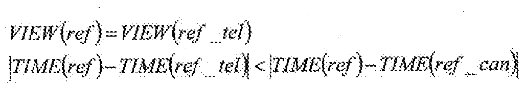
- the reference information used in the most pixels is mv-tel [S205], and processing is performed based on the following conditional expression [S206 to S210].
- TIME () is the display time of the frame corresponding to the given reference frame number.
- This conditional expression means that it is determined whether or not the reference frame ref-tel is closer in time to the reference frame ref of the encoding target block blk than the reference frame ref-can.
- the reference frame ref of the encoding target block blk is set as the search target using the decoded image information of the encoding target frame at the position of p-can, and the search center is set to mv — Set to can, find the corresponding region on the reference frame ref, change the displacement from the search center (corresponding information) to mv—canBM [S208], rewrite ref—can to ref, mv to can mv to canBM ⁇ Power [S209].
- the reference frame ref of the encoding target block blk is used as the search target, and the adjacent region of the encoding target block blk. It is also possible to use a method of searching for a region that matches the adjacent region of the force coding target block blk using a method of searching for a region that matches the reference region associated with.
- the reference information changing unit 1 1 1 executes the flowchart of FIG.
- the prediction reference information prediction data stored in the prediction reference information prediction data memory 108 is processed in such a manner as shown in FIG.
- prediction reference information prediction data having FIN force SO is extracted and set as p-can [S 301].
- the reference frame number of p—can is set to ref—can
- the reference information of p—can is set to m V—can [S302].
- ref-can is equal to the reference frame number ref of the reference frame to be used when encoding the block blk [S 303], FIN is set to 1 and [S 304], p_can is set.
- the prediction reference information is stored in the prediction data memory 108 as it is [S336, S337].
- the reference frame used in the most pixels when encoding the area (reference area) indicated by mv-can on the frame ref-can is defined as ref-tel
- ref-tel the reference information used in most pixels is mv-tel [S 305]
- the following processing [S 306 to S 335] is performed, and then p-can is Prediction reference information is stored in the prediction data memory 108 [S 336, S 337].
- the display time of the encoding target frame cur and the display time of the reference frame ref of the encoding target block are compared [S308], and if they are the same, the change between video cameras in the block blk is predicted. If it is different, execute the process [Figure 8: S321 to S335] when predicting the temporal change of the video in the block blk.
- VIEW 0 in the flowchart of FIG. 7 represents a function that returns a viewpoint (camera) index for photographing a frame corresponding to a given frame number.
- the parallax to the frame ref of the adjacent area is converted to mv-transl using the camera parameters of frame cur, frame ref—can, and frame ref [S310], ref—can is rewritten to ref, and mv is can mv write on transl! I get [S311].
- the geometric transformation performed in S310 is executed according to the following procedure.
- the position force mp can be expressed by p_can mv—determine the center position of the region (reference region) shifted by can 3 ⁇ 4 pos—can
- Trans (src, dst, pix, d) can be defined by the following formula, and in the case of the distance force from the pixel at the position pix on the image at the viewpoint src to the subject, the pixel pix on the image at the viewpoint dst Represents the homogeneous coordinate value of the corresponding pixel p.
- A, R, and t are camera parameters, which respectively indicate an internal parameter, a rotation parameter, and a translation parameter.
- Internal parameters and rotation parameters are 3 X 3 matrices, and t is a 3D vector vector.
- those with ⁇ added to the coordinate values indicate homogeneous coordinate values.
- FIG. 13 shows an example of the geometric transformation performed in the process of S310. For ease of viewing, mv-can and mv-transl are shown shifted up and down.
- mv-can is converted to mv-transl, and in S311, mv-can is rewritten to mv-transl.
- this time interval is greater than or equal to THl
- the corresponding region on the reference frame ref is obtained using the decoded image information of the encoding target frame at the p-can position, and the displacement from the p-can position (corresponding to Information) is mv-BM [S315], ref-can is rewritten to ref, and mv-can is rewritten to mv_BM [S316].
- the geometric transformation performed in S318 is executed according to the following procedure.
- Trans (ref_can, ref_tel, pos_can, x) is prolonged (indicated by adding ⁇ to p above)
- FIG. 14 shows an example of geometric transformation performed in the process of S318.
- TIME (ref_can) TIME (ref_tel), VIEW (ref) ⁇ VIEW (ref—tel), the process of geometric transformation from mv—tel to mv—trans2 is performed. Processing to rewrite mv-can to mv-trans2 (the dashed line in the figure is the processing result) will be performed.
- the frame ref—can is the frame ref.
- the search center is determined to be close in time, the search center is set to mv-can using the decoded image information of the frame to be encoded at the p-can position, and the corresponding region on the reference frame ref
- the displacement from the search center is mv-canBM [S325]
- ref-can is rewritten to ref
- mv-canBM is squeezed into mv-can [S326].
- the search center is set to mv-tel using the decoded image information of the encoding target frame at the position of p-can, and the reference is made. Find the corresponding area on the reference frame ref, change the displacement from the search center (corresponding information) to mv—telBM [S330], rewrite ref—can to ref, mv—can to mv—tel and mv—telBM Rewrite to [S331].
- the matching ratio of the shooting areas of VIEW (cur) and VIEW (ref—tel) is It is determined whether or not it is greater than the predetermined threshold value TH2! /, [S332].
- Diff (caml, cam2) represents a matching degree of the imaging area, one camera (determined in advance either, it fits threshold TH2 is selected) both cameras for shadow region capable shooting in Gives the percentage of the area that can be shot with. However, only real space from the camera to the distance given separately is considered. Further, the given threshold value T H2 is assumed to be greater than the smallest Diff value! / For all camera combinations! /.
- prediction reference information prediction data having FIN force SO is extracted and set as p-can [S401].
- the reference frame number of p—can is set to ref—can
- the reference information of p—can is set to m V—can [S402].
- the reference that is used by the most pixels when encoding the region (reference region) on the frame ref—can where p—can (adjacent region) is shifted by mv—can After performing the following processing [S406 to S451] with ref_tel as the frame and the reference information in this area as the reference frame of ref—tel and the reference information used by most pixels as mv-tel [S405] , P—can is stored in the prediction reference information prediction data memory 108 [S452, S453].
- the parallax to the frame ref can of the area (adjacent area) of the position of P can in the frame cur in the same manner as the processing in S310 described above mv can To the disparity mv—transl of the adjacent region to the frame ref using the camera parameters of the frame cur, the frame ref—can, and the frame ref [S410], and writing the ref—can to the r ef , Rewrite mv one can to mv one transl [S411].
- geometric transformation process performed in S410 is the same as the geometric transformation process described in S310.
- the camera that shot the frame ref—tel is the same as the camera that shot the frame ref
- the geometric transformation performed in S415 is executed according to the following procedure.
- Trans (ref_can, ref_tel, pos_can, x) is prolonged (indicated by adding ⁇ to p above)
- FIG. 15 shows an example of geometric transformation performed in the process of S415. For ease of viewing, mv-tel and mv-tran3 are shown shifted up and down.
- mv—tel is converted to mv—trans3.
- the process of rewriting can to mv-trans3 (the broken line in the figure is the result of the process) is performed.
- the frame ref—can display time and the frame ref—tel display time are determined in S412. If it is determined that IJ is different, the time interval between frame cur and frame ref—tel is given in advance. Judge whether it is smaller than the threshold value TH1 [S417]
- the corresponding region on the reference frame ref is obtained using the decoded image information of the frame to be encoded at the p-can position, and the displacement from the p-can position (corresponding information)
- mv—can is rewritten to mv—BM [S420]
- the search center is set to mv-can using the decoded image information of the frame to be encoded at the position of p-can, and the reference frame ref The corresponding region of the search is obtained, the displacement (corresponding information) from the search center is mv-canBM [S426], ref-can is rewritten to ref, and mv-canBM is applied to mv-can [S427].
- search in S429 may be performed only when the center of the corresponding region is around a straight line obtained by the following procedure by using a restriction between cameras.
- the maximum and minimum values of X to be changed are not determined, but they may be set in advance.
- FIG. 16 shows an example of the geometric transformation performed in the process of S433.
- VIEW (cur) VIEW (rei), VIEW (cur) ⁇ VIEW (ref_can)
- the search center is set to mv-can using the decoded image information of the encoding target frame at the position of p-can, and the corresponding region on the reference frame ref is set to The displacement (corresponding information) from the search center is mv—mark iBM2 [S436] ref—can is rewritten to ref, and mv—mark iBM2 is added to mv—can [S437]
- search in S436 may be performed only when the center of the corresponding region is around the straight line obtained by the following procedure by using the restriction between cameras.
- the maximum and minimum values of X to be changed are not determined, but they may be set in advance.
- the corresponding region on the reference frame ref is obtained using the decoded image information of the encoding target frame at the p-can position, and the displacement from the p-can position (corresponding information) is calculated.
- mv—BM as [S440]
- ref—can is rewritten as ref
- mv—can is rewritten as mv—BM [S441].
- p-can adjacent block position in the image taken with VIEW (ref-can) is set to mv in the same way as in S318.
- Parallax to the image taken with VIEW (rei) of the reference region mv—to trans2 perform geometric transformation using VIEW (ref—can), VIEW (ref—tel), and VIEW (rei) camera parameters [S444], rewrite ref—can to ref, mv—can mv — Add trans2 [S445].
- FIG. 17 shows an example of geometric transformation performed in the process of S444. For ease of viewing, mv-tel and mv-trans2 are shown shifted up and down.
- the decoded image information of the frame to be encoded at the position of p-can is used.
- the search center is set to mv—can, the corresponding region on the reference frame ref is obtained, the displacement from the search center (corresponding information) is set to mv—mark iBM2 [S446], and ref—can is rewritten to ref. Add mv—mark iBM2 to mv—can [S447].
- search in S446 uses only the constraints between the cameras, and only searches for the case where the center of the corresponding region is around the straight line obtained by the same procedure as in the process of S336 described above. Good.
- the reference information changing unit 111 performs the prediction reference information prediction data memory 108 in the form shown in FIGS. 1 and 2 by executing the flowcharts of FIGS. Processing is performed to change the stored prediction reference information prediction data.
- FIG. 18 shows an embodiment of the moving picture decoding apparatus 200 according to the present invention.
- the moving picture decoding apparatus 200 is configured to calculate a difference image with respect to a predicted image of an image to be decoded.
- a differential image decoding unit 201 that decodes encoded data
- a differential reference information decoding unit 202 that decodes encoded data of differential reference information with respect to prediction reference information of reference information when generating a predicted image
- a predicted image A reference frame specifying information decoding unit 203 for decoding the encoded data of the reference frame specifying information at the time of generation, and a decoding target frame using the reference frame, the reference frame specifying information, and the reference information that are already decoded frames
- a predicted image generating unit 204 that generates a predicted image
- a reference frame memory 205 that stores a decoded image obtained by summing the predicted image and the decoded difference image, and predicted reference information prediction data
- prediction reference information Prediction reference information generation unit 206 that generates prediction reference information from candidate reference information
- prediction reference information prediction data memory 207 that stores prediction reference information prediction data
- FIG. 19 shows a flow cheat executed by the moving picture decoding apparatus 200 configured as described above.
- the encoded data of the difference image, the encoded data of the difference reference information, and the encoded data of the reference frame designation information are input to the moving image decoding apparatus 200, and each of them is input to the difference image decoding unit 201.
- the difference reference information decoding unit 202 and the reference frame designation information decoding unit 203 are sent [S501].
- the entire image is divided into regions, and decoding is performed for each region [S502 to S515].
- the block (area) index is represented as blk
- the total number of blocks contained in one image is represented as MaxBlk.
- the encoded data of the reference frame designation information is decoded to obtain the reference frame designation information ref [S503], and the prediction reference for predicting the reference information for the reference frame ref
- the encoded reference data is decoded to obtain differential reference information mvd [S508], consisting of the sum of pmv and mvd Generate reference information mv [S509].
- the prediction image Pre is generated using the reference frame ref and the reference information mv [S 510], the encoded data of the difference image is decoded, and the difference image Sub is obtained [S511], The decoded image Dec is generated by calculating the sum of each pixel with Sub [S512].
- the decoded image Dec, the reference information mv that is information used to decode the block blk, and the reference frame designation information ref are respectively stored in the reference frame memory 205, the reference information accumulation memory 208, and the reference frame designation information accumulation. Store in memory 210 [S 513].
- each frame was decoded after the decoding process for all the blocks included in the frame was completed and after all the frames having the display time before that frame were output.
- a frame is output from the video decoding device 200.
- MV and REF are stored in the reference information storage memory 208 and the reference frame designation information storage memory 210 in association with the block index or the position in the image, respectively.
- the blocks adjacent to the top, left, and upper right can be set as S I'll do it.
- the reference information of these three adjacent blocks is set in the prediction reference information prediction data. However, if the block is outside the screen, It shall be excluded from the supplement.
- the prediction reference information prediction data in the prediction reference information prediction data memory 207 is taken out, changed by the reference information changing unit 209, and stored again in the prediction reference information prediction data memory 207 [S 506 ].
- the processing performed here will be described in detail later.
- the prediction reference information pmv is generated from the plurality of reference information stored in the prediction reference information prediction data memory 207 [S507]. Specifically, prediction reference information pmv is created by taking an intermediate value of prediction reference information prediction data for each component of reference information.
- the reference information is expressed as a two-dimensional vector of X—Y
- the intermediate value of the corresponding component of multiple prediction reference information prediction data is obtained, and pmv is determined as the component value.
- an average value, a maximum value, a minimum value, etc. may be used based on any standard. However, it is necessary to use the same standard as that used by the video encoding device.
- FIN is initialized to 0 for all the prediction reference information prediction data stored in the prediction reference information prediction data memory 207, and until all FIN power losses are reached, FIG. 5 to FIG.
- FIG. 5 shows a flowchart in a case where all input frames and reference frames are images taken from the same camera.
- FIGS. 6 to 8 show flow charts when a multi-viewpoint image is input and the reference frame is an image having the same display time (shooting time) as the input frame or an image taken by the same camera.
- FIGS. 9 to 12 show flowcharts when a multi-viewpoint image is inputted and any already encoded frame can be used as a reference frame.
- the decoding apparatus it may be understood as a flowchart when any already decoded frame can be used as a reference frame.
- a method of generating mv_tel in addition to taking the mode value as described above, a method of generating an intermediate value or an average value for each component may be used! /.
- intra-frame coding is not described in the embodiment, as one method of creating a predicted image, for example, it can be easily added by assigning another number as reference frame designation information. Can do.
- the above-described moving picture encoding and decoding processes can be realized by a computer and a software program, and the program can be recorded on a computer-readable recording medium and provided. It can also be provided through a network.
- the present embodiment includes steps corresponding to the operations of the respective units of the moving image encoding device and the moving image decoding device.
- the video encoding method and video decoding method of the invention can be realized.
- the reference information used when encoding the area adjacent to the encoding target area is encoded using the encoding information used when encoding the reference area.
Description
Claims
Priority Applications (7)
| Application Number | Priority Date | Filing Date | Title |
|---|---|---|---|
| CN2007800386378A CN101529918B (zh) | 2006-10-30 | 2007-10-23 | 预测参照信息生成方法、活动图像的编码及解码方法及其装置 |
| BRPI0717639 BRPI0717639A2 (pt) | 2006-10-30 | 2007-10-23 | Método de geração de informações de referência preditas, métodos de codificação de decodificação de vídeo, aparelhos destinados aos mesmos, programas destinados aos mesmos, e mídias de armazenamento que armazenam os programas |
| EP07830370A EP2079242A4 (en) | 2006-10-30 | 2007-10-23 | METHOD FOR GENERATING PREDICTIVE REFERENCE INFORMATION, DYNAMIC IMAGE ENCODING AND DECODING METHOD, DEVICE THEREOF, PROGRAM THEREOF, AND STORAGE MEDIUM CONTAINING THE PROGRAM |
| US12/445,047 US8355438B2 (en) | 2006-10-30 | 2007-10-23 | Predicted reference information generating method, video encoding and decoding methods, apparatuses therefor, programs therefor, and storage media which store the programs |
| CA 2665781 CA2665781C (en) | 2006-10-30 | 2007-10-23 | Predicted reference information generating method, video encoding and decoding methods, apparatuses therefor, programs therefor, and storage media which store the programs |
| JP2008542055A JP4999859B2 (ja) | 2006-10-30 | 2007-10-23 | 予測参照情報生成方法、動画像符号化及び復号方法、それらの装置、及びそれらのプログラム並びにプログラムを記録した記憶媒体 |
| US13/711,904 US8675735B2 (en) | 2006-10-30 | 2012-12-12 | Predicted reference information generating method, video encoding and decoding methods, apparatuses therefor, programs therefor, and storage media which store the programs |
Applications Claiming Priority (2)
| Application Number | Priority Date | Filing Date | Title |
|---|---|---|---|
| JP2006-293929 | 2006-10-30 | ||
| JP2006293929 | 2006-10-30 |
Related Child Applications (2)
| Application Number | Title | Priority Date | Filing Date |
|---|---|---|---|
| US12/445,047 A-371-Of-International US8355438B2 (en) | 2006-10-30 | 2007-10-23 | Predicted reference information generating method, video encoding and decoding methods, apparatuses therefor, programs therefor, and storage media which store the programs |
| US13/711,904 Division US8675735B2 (en) | 2006-10-30 | 2012-12-12 | Predicted reference information generating method, video encoding and decoding methods, apparatuses therefor, programs therefor, and storage media which store the programs |
Publications (1)
| Publication Number | Publication Date |
|---|---|
| WO2008053746A1 true WO2008053746A1 (fr) | 2008-05-08 |
Family
ID=39344089
Family Applications (1)
| Application Number | Title | Priority Date | Filing Date |
|---|---|---|---|
| PCT/JP2007/070636 WO2008053746A1 (fr) | 2006-10-30 | 2007-10-23 | Procédé de génération d'informations de référence prédictives, procédé de codage et de décodage d'image dynamiques, leur dispositif, leur programme et support de stockage contenant le programme |
Country Status (10)
| Country | Link |
|---|---|
| US (2) | US8355438B2 (ja) |
| EP (1) | EP2079242A4 (ja) |
| JP (1) | JP4999859B2 (ja) |
| KR (1) | KR101023263B1 (ja) |
| CN (1) | CN101529918B (ja) |
| BR (1) | BRPI0717639A2 (ja) |
| CA (1) | CA2665781C (ja) |
| RU (1) | RU2434361C2 (ja) |
| TW (2) | TWI376158B (ja) |
| WO (1) | WO2008053746A1 (ja) |
Cited By (12)
| Publication number | Priority date | Publication date | Assignee | Title |
|---|---|---|---|---|
| WO2010016534A1 (ja) * | 2008-08-08 | 2010-02-11 | シャープ株式会社 | 動画像符号化装置および動画像復号装置 |
| WO2012090497A1 (ja) * | 2010-12-28 | 2012-07-05 | パナソニック株式会社 | 動画像符号化方法、動画像復号方法、動画像符号化装置、動画像復号装置、及び動画像符号化復号装置 |
| WO2012108315A1 (ja) * | 2011-02-07 | 2012-08-16 | シャープ株式会社 | 予測情報生成方法、画像符号化方法、画像復号方法、予測情報生成装置、予測情報生成プログラム、画像符号化装置、画像符号化プログラム、画像復号装置および画像復号プログラム |
| WO2013108613A1 (ja) * | 2012-01-17 | 2013-07-25 | パナソニック株式会社 | 動画像符号化方法、動画像復号化方法、動画像符号化装置、動画像復号化装置および動画像符号化復号化装置 |
| JP2014512720A (ja) * | 2011-02-21 | 2014-05-22 | サムスン エレクトロニクス カンパニー リミテッド | 多視点ビデオの符号化方法及び装置、その復号化方法及び装置 |
| JP2014514862A (ja) * | 2011-04-20 | 2014-06-19 | クゥアルコム・インコーポレイテッド | ビデオコード化における動きベクトル予測 |
| JP5664762B2 (ja) * | 2011-03-17 | 2015-02-04 | 富士通株式会社 | 動画像復号方法、動画像符号化方法、動画像復号装置及び動画像復号プログラム |
| JP2015046920A (ja) * | 2014-10-15 | 2015-03-12 | 富士通株式会社 | 動画像復号方法、動画像符号化方法、動画像復号装置及び動画像復号プログラム |
| US9503720B2 (en) | 2012-03-16 | 2016-11-22 | Qualcomm Incorporated | Motion vector coding and bi-prediction in HEVC and its extensions |
| JP2016537839A (ja) * | 2013-09-26 | 2016-12-01 | クゥアルコム・インコーポレイテッドQualcomm Incorporated | Hevcにおけるサブ予測ユニット(pu)ベースの時間的動きベクトル予測および3d−hevcにおけるサブpu設計 |
| US10200709B2 (en) | 2012-03-16 | 2019-02-05 | Qualcomm Incorporated | High-level syntax extensions for high efficiency video coding |
| JP2020058055A (ja) * | 2010-08-11 | 2020-04-09 | ジーイー ビデオ コンプレッション エルエルシー | 多視点信号コーデック |
Families Citing this family (49)
| Publication number | Priority date | Publication date | Assignee | Title |
|---|---|---|---|---|
| JPWO2009084340A1 (ja) * | 2007-12-28 | 2011-05-19 | シャープ株式会社 | 動画像符号化装置、および、動画像復号装置 |
| PT2988500T (pt) | 2009-03-23 | 2017-09-26 | Ntt Docomo Inc | Dispositivo de codificação preditiva de imagem, a um método de codificação preditiva de imagem, a um programa de codificação preditiva de imagem, a um dispositivo de descodificação preditiva de imagem, a um método de descodificação preditiva de imagem e a um programa de descodificação preditiva de imagem |
| JP5237500B2 (ja) * | 2010-02-23 | 2013-07-17 | 日本電信電話株式会社 | 動きベクトル推定方法、多視点映像符号化方法、多視点映像復号方法、動きベクトル推定装置、多視点映像符号化装置、多視点映像復号装置、動きベクトル推定プログラム、多視点映像符号化プログラム、及び多視点映像復号プログラム |
| CN102823248B (zh) * | 2010-04-08 | 2015-06-24 | 株式会社东芝 | 图像编码方法以及图像编码装置 |
| KR101903643B1 (ko) * | 2010-07-20 | 2018-10-02 | 가부시키가이샤 엔.티.티.도코모 | 화상 예측 복호 장치 및 화상 예측 복호 방법 |
| KR20120012385A (ko) | 2010-07-31 | 2012-02-09 | 오수미 | 인트라 예측 부호화 장치 |
| KR101373814B1 (ko) * | 2010-07-31 | 2014-03-18 | 엠앤케이홀딩스 주식회사 | 예측 블록 생성 장치 |
| JP5524762B2 (ja) | 2010-08-12 | 2014-06-18 | 日本電信電話株式会社 | 映像符号化方法,映像復号方法,映像符号化装置,映像復号装置およびそれらのプログラム |
| US11284072B2 (en) | 2010-08-17 | 2022-03-22 | M&K Holdings Inc. | Apparatus for decoding an image |
| EP3125556B1 (en) * | 2010-08-17 | 2018-10-17 | M&K Holdings Inc. | Method for encoding an intra prediction mode |
| KR20120016991A (ko) | 2010-08-17 | 2012-02-27 | 오수미 | 인터 프리딕션 방법 |
| DK3657798T3 (da) * | 2010-10-06 | 2022-10-31 | Ntt Docomo Inc | Biforudsigelsesbilledafkodningsfremgangsmåde |
| KR101418100B1 (ko) * | 2010-10-06 | 2014-07-14 | 에스케이 텔레콤주식회사 | 모순 검증을 이용한 부호화 및 복호화 방법과 장치 |
| JP5281632B2 (ja) * | 2010-12-06 | 2013-09-04 | 日本電信電話株式会社 | 多視点画像符号化方法,多視点画像復号方法,多視点画像符号化装置,多視点画像復号装置およびそれらのプログラム |
| EP3136727B1 (en) | 2011-04-12 | 2018-06-13 | Sun Patent Trust | Motion-video coding method and motion-video coding apparatus |
| KR20120118780A (ko) * | 2011-04-19 | 2012-10-29 | 삼성전자주식회사 | 다시점 비디오의 움직임 벡터 부호화 방법 및 장치, 그 복호화 방법 및 장치 |
| AU2012260302B2 (en) | 2011-05-24 | 2016-11-17 | Sun Patent Trust | Image coding method, image coding apparatus, image decoding method, image decoding apparatus, and image coding and decoding apparatus |
| PL3614665T3 (pl) | 2011-05-27 | 2022-07-04 | Sun Patent Trust | Sposób kodowania obrazów, urządzenie do kodowania obrazów, sposób dekodowania obrazów, urządzenie do dekodowania obrazów, i urządzenie do kodowania i dekodowania obrazów |
| US9485518B2 (en) | 2011-05-27 | 2016-11-01 | Sun Patent Trust | Decoding method and apparatus with candidate motion vectors |
| SG194746A1 (en) | 2011-05-31 | 2013-12-30 | Kaba Gmbh | Image encoding method, image encoding device, image decoding method, image decoding device, and image encoding/decoding device |
| US8989271B2 (en) | 2011-05-31 | 2015-03-24 | Panasonic Intellectual Property Corporation Of America | Decoding method and apparatus with candidate motion vectors |
| EP2536143B1 (en) * | 2011-06-16 | 2015-01-14 | Axis AB | Method and a digital video encoder system for encoding digital video data |
| US20140104383A1 (en) * | 2011-06-22 | 2014-04-17 | Sony Corporation | Image processing device and method |
| PL2728878T3 (pl) | 2011-06-30 | 2020-06-15 | Sun Patent Trust | Sposób dekodowania obrazów, sposób kodowania obrazów, urządzenie do dekodowania obrazów, urządzenie do kodowania obrazów oraz urządzenie do kodowania/dekodowania obrazów |
| IN2014CN00729A (ja) | 2011-08-03 | 2015-04-03 | Panasonic Corp | |
| JP6039178B2 (ja) * | 2011-09-15 | 2016-12-07 | シャープ株式会社 | 画像符号化装置、画像復号装置、並びにそれらの方法及びプログラム |
| TWI577184B (zh) * | 2011-09-28 | 2017-04-01 | Jvc Kenwood Corp | A motion picture decoding apparatus, a motion picture decoding method, and a recording medium |
| EP3923572A1 (en) | 2011-10-19 | 2021-12-15 | Sun Patent Trust | Image encoding method, image encoding device, image decoding method, and picture decoding device |
| US10390016B2 (en) | 2011-11-04 | 2019-08-20 | Infobridge Pte. Ltd. | Apparatus of encoding an image |
| KR20130049524A (ko) | 2011-11-04 | 2013-05-14 | 오수미 | 인트라 예측 블록 생성 방법 |
| DK3703371T3 (da) * | 2011-12-16 | 2021-09-06 | Jvckenwood Corp | Indretning til dynamisk billedkodning, fremgangsmåde til dynamisk billedkodning, program til dynamisk billedkodning, indretning til dynamisk billedafkodning, fremgangsmåde til dynamisk billedafkodning og program til dynamisk billedafkodning |
| US9762904B2 (en) | 2011-12-22 | 2017-09-12 | Qualcomm Incorporated | Performing motion vector prediction for video coding |
| WO2013105207A1 (en) * | 2012-01-10 | 2013-07-18 | Panasonic Corporation | Video encoding method, video encoding apparatus, video decoding method and video decoding apparatus |
| CN104185993B (zh) * | 2012-03-30 | 2019-02-12 | 索尼公司 | 图像处理设备和方法以及记录介质 |
| ES2912134T3 (es) * | 2012-04-12 | 2022-05-24 | Jvckenwood Corp | Construcción de lista de candidatos de fusión |
| US9860555B2 (en) | 2012-05-22 | 2018-01-02 | Lg Electronics Inc. | Method and apparatus for processing video signal |
| CA2877268C (en) | 2012-06-19 | 2020-07-21 | Lg Electronics Inc. | Method and device for processing video signal |
| KR102179087B1 (ko) * | 2012-06-29 | 2020-11-18 | 벨로스 미디어 인터내셔널 리미티드 | 복호 장치 및 복호 방법 |
| US10334259B2 (en) * | 2012-12-07 | 2019-06-25 | Qualcomm Incorporated | Advanced residual prediction in scalable and multi-view video coding |
| US9544566B2 (en) | 2012-12-14 | 2017-01-10 | Qualcomm Incorporated | Disparity vector derivation |
| US9800857B2 (en) * | 2013-03-08 | 2017-10-24 | Qualcomm Incorporated | Inter-view residual prediction in multi-view or 3-dimensional video coding |
| WO2015056700A1 (ja) * | 2013-10-17 | 2015-04-23 | 日本電信電話株式会社 | 映像符号化装置及び方法、及び、映像復号装置及び方法 |
| US9807411B2 (en) * | 2014-03-18 | 2017-10-31 | Panasonic Intellectual Property Management Co., Ltd. | Image coding apparatus, image decoding apparatus, image processing system, image coding method, and image decoding method |
| JP6463900B2 (ja) * | 2014-04-17 | 2019-02-06 | キヤノン株式会社 | 画像符号化装置及びその制御方法 |
| CN115118967A (zh) | 2015-11-20 | 2022-09-27 | 韩国电子通信研究院 | 用于对图像进行编/解码的方法和存储比特流的方法 |
| CN116489350A (zh) | 2015-11-20 | 2023-07-25 | 韩国电子通信研究院 | 对图像进行编/解码的方法和装置 |
| GB2556319A (en) * | 2016-07-14 | 2018-05-30 | Nokia Technologies Oy | Method for temporal inter-view prediction and technical equipment for the same |
| RU2666275C1 (ru) * | 2017-11-13 | 2018-09-06 | ДжейВиСи КЕНВУД КОРПОРЕЙШН | Устройство и способ кодирования движущегося изображения, долговременный считываемый компьютером носитель записи, на который записана программа кодирования изображения |
| CN112714322B (zh) * | 2020-12-28 | 2023-08-01 | 福州大学 | 一种面向游戏视频的帧间参考优化方法 |
Citations (6)
| Publication number | Priority date | Publication date | Assignee | Title |
|---|---|---|---|---|
| JPH08205164A (ja) * | 1994-12-30 | 1996-08-09 | Daewoo Electron Co Ltd | 動きベクトル決定方法及び動きベクトル推定装置 |
| JPH10136374A (ja) * | 1996-10-28 | 1998-05-22 | Nec Corp | 動ベクトル予測装置 |
| JP2004056823A (ja) * | 2002-07-16 | 2004-02-19 | Samsung Electronics Co Ltd | 動きベクトル符号化/復号化方法及びその装置 |
| JP2004336369A (ja) * | 2003-05-07 | 2004-11-25 | Ntt Docomo Inc | 動画像符号化装置、動画像復号化装置、動画像符号化方法、動画像復号化方法、動画像符号化プログラム及び動画像復号化プログラム |
| WO2006073116A1 (ja) * | 2005-01-07 | 2006-07-13 | Nippon Telegraph And Telephone Corporation | 映像符号化方法及び装置、映像復号方法及び装置、それらのプログラムおよびそれらプログラムを記録した記録媒体 |
| JP2006293929A (ja) | 2005-04-14 | 2006-10-26 | Matsushita Electric Ind Co Ltd | データ伝送装置 |
Family Cites Families (12)
| Publication number | Priority date | Publication date | Assignee | Title |
|---|---|---|---|---|
| CN1127969A (zh) | 1995-01-26 | 1996-07-31 | 大宇电子株式会社 | 用于在帧削减视频编码器中检测运动矢量的方法及装置 |
| FR2756399B1 (fr) | 1996-11-28 | 1999-06-25 | Thomson Multimedia Sa | Procede et dispositif de compression video pour images de synthese |
| JP3519594B2 (ja) | 1998-03-03 | 2004-04-19 | Kddi株式会社 | ステレオ動画像用符号化装置 |
| CN1201598C (zh) | 2000-03-31 | 2005-05-11 | 皇家菲利浦电子有限公司 | 两种相关数据序列的编码 |
| JP4608136B2 (ja) | 2001-06-22 | 2011-01-05 | オリンパス株式会社 | 動きベクトル及び視差ベクトル検出装置 |
| US7154952B2 (en) * | 2002-07-19 | 2006-12-26 | Microsoft Corporation | Timestamp-independent motion vector prediction for predictive (P) and bidirectionally predictive (B) pictures |
| CN1258925C (zh) * | 2003-06-27 | 2006-06-07 | 中国科学院计算技术研究所 | 多视角视频编解码预测补偿方法及装置 |
| US7778328B2 (en) | 2003-08-07 | 2010-08-17 | Sony Corporation | Semantics-based motion estimation for multi-view video coding |
| JP4421940B2 (ja) | 2004-05-13 | 2010-02-24 | 株式会社エヌ・ティ・ティ・ドコモ | 動画像符号化装置および方法、並びに動画像復号化装置および方法 |
| US7792188B2 (en) | 2004-06-27 | 2010-09-07 | Apple Inc. | Selecting encoding types and predictive modes for encoding video data |
| US7933337B2 (en) | 2005-08-12 | 2011-04-26 | Microsoft Corporation | Prediction of transform coefficients for image compression |
| TWI344791B (en) * | 2006-07-12 | 2011-07-01 | Lg Electronics Inc | A method and apparatus for processing a signal |
-
2007
- 2007-10-23 JP JP2008542055A patent/JP4999859B2/ja active Active
- 2007-10-23 US US12/445,047 patent/US8355438B2/en active Active
- 2007-10-23 KR KR20097007723A patent/KR101023263B1/ko active IP Right Grant
- 2007-10-23 RU RU2009114363A patent/RU2434361C2/ru active
- 2007-10-23 CA CA 2665781 patent/CA2665781C/en active Active
- 2007-10-23 CN CN2007800386378A patent/CN101529918B/zh active Active
- 2007-10-23 WO PCT/JP2007/070636 patent/WO2008053746A1/ja active Application Filing
- 2007-10-23 BR BRPI0717639 patent/BRPI0717639A2/pt not_active IP Right Cessation
- 2007-10-23 EP EP07830370A patent/EP2079242A4/en not_active Withdrawn
- 2007-10-26 TW TW96140158A patent/TWI376158B/zh active
- 2007-10-26 TW TW101112192A patent/TWI502968B/zh active
-
2012
- 2012-12-12 US US13/711,904 patent/US8675735B2/en active Active
Patent Citations (6)
| Publication number | Priority date | Publication date | Assignee | Title |
|---|---|---|---|---|
| JPH08205164A (ja) * | 1994-12-30 | 1996-08-09 | Daewoo Electron Co Ltd | 動きベクトル決定方法及び動きベクトル推定装置 |
| JPH10136374A (ja) * | 1996-10-28 | 1998-05-22 | Nec Corp | 動ベクトル予測装置 |
| JP2004056823A (ja) * | 2002-07-16 | 2004-02-19 | Samsung Electronics Co Ltd | 動きベクトル符号化/復号化方法及びその装置 |
| JP2004336369A (ja) * | 2003-05-07 | 2004-11-25 | Ntt Docomo Inc | 動画像符号化装置、動画像復号化装置、動画像符号化方法、動画像復号化方法、動画像符号化プログラム及び動画像復号化プログラム |
| WO2006073116A1 (ja) * | 2005-01-07 | 2006-07-13 | Nippon Telegraph And Telephone Corporation | 映像符号化方法及び装置、映像復号方法及び装置、それらのプログラムおよびそれらプログラムを記録した記録媒体 |
| JP2006293929A (ja) | 2005-04-14 | 2006-10-26 | Matsushita Electric Ind Co Ltd | データ伝送装置 |
Non-Patent Citations (5)
| Title |
|---|
| "Editor's Proposed Draft Text Modifications for Joint Video Specification (ITU-T Rec. H.264 / ISO/IEC 14496-10 AVC), Draft 7", FINAL COMMITTEE DRAFT, DOCUMENT JVT-E022, September 2002 (2002-09-01), pages 63 - 64 |
| ALEXIS; MICHAEL; TOURAPIS: "Direct Prediction for Predictive(P) and Bidirectionally Predictive(B) frames in Video Coding", JVT-C128, May 2002 (2002-05-01), pages 1 - 11, XP002354618 |
| HIDEAKI KIMATA; MASAKI KITAHARA: "Preliminary results on multiple view video coding ( 3DAV)", M10976 MPEG REDMOND MEETING, July 2004 (2004-07-01) |
| SADAATSU KATO; CHOONG SENG BOON: "Motion Vector Prediction for Multiple Reference Frame Video Coding Using Temporal Motion Vector Normalization", PCSJ2004, PROCEEDINGS OF THE 19TH PICTURE CODING SYMPOSIUM OF JAPAN, November 2004 (2004-11-01), pages 2 - 18 |
| See also references of EP2079242A4 * |
Cited By (21)
| Publication number | Priority date | Publication date | Assignee | Title |
|---|---|---|---|---|
| WO2010016534A1 (ja) * | 2008-08-08 | 2010-02-11 | シャープ株式会社 | 動画像符号化装置および動画像復号装置 |
| US11843757B2 (en) | 2010-08-11 | 2023-12-12 | Ge Video Compression, Llc | Multi-view signal codec |
| JP7189272B2 (ja) | 2010-08-11 | 2022-12-13 | ジーイー ビデオ コンプレッション エルエルシー | 多視点信号コーデック |
| US11330242B2 (en) | 2010-08-11 | 2022-05-10 | Ge Video Compression, Llc | Multi-view signal codec |
| JP2021141602A (ja) * | 2010-08-11 | 2021-09-16 | ジーイー ビデオ コンプレッション エルエルシー | 多視点信号コーデック |
| JP2020058055A (ja) * | 2010-08-11 | 2020-04-09 | ジーイー ビデオ コンプレッション エルエルシー | 多視点信号コーデック |
| WO2012090497A1 (ja) * | 2010-12-28 | 2012-07-05 | パナソニック株式会社 | 動画像符号化方法、動画像復号方法、動画像符号化装置、動画像復号装置、及び動画像符号化復号装置 |
| WO2012108315A1 (ja) * | 2011-02-07 | 2012-08-16 | シャープ株式会社 | 予測情報生成方法、画像符号化方法、画像復号方法、予測情報生成装置、予測情報生成プログラム、画像符号化装置、画像符号化プログラム、画像復号装置および画像復号プログラム |
| JP2014512720A (ja) * | 2011-02-21 | 2014-05-22 | サムスン エレクトロニクス カンパニー リミテッド | 多視点ビデオの符号化方法及び装置、その復号化方法及び装置 |
| JP5664762B2 (ja) * | 2011-03-17 | 2015-02-04 | 富士通株式会社 | 動画像復号方法、動画像符号化方法、動画像復号装置及び動画像復号プログラム |
| JP2016026435A (ja) * | 2011-04-20 | 2016-02-12 | クゥアルコム・インコーポレイテッドQualcomm Incorporated | ビデオコード化における動きベクトル予測 |
| US9485517B2 (en) | 2011-04-20 | 2016-11-01 | Qualcomm Incorporated | Motion vector prediction with motion vectors from multiple views in multi-view video coding |
| US9584823B2 (en) | 2011-04-20 | 2017-02-28 | Qualcomm Incorporated | Determining motion vectors for motion vector prediction based on motion vector type in video coding |
| US9247249B2 (en) | 2011-04-20 | 2016-01-26 | Qualcomm Incorporated | Motion vector prediction in video coding |
| JP2014514861A (ja) * | 2011-04-20 | 2014-06-19 | クゥアルコム・インコーポレイテッド | ビデオコード化における動きベクトル予測 |
| JP2014514862A (ja) * | 2011-04-20 | 2014-06-19 | クゥアルコム・インコーポレイテッド | ビデオコード化における動きベクトル予測 |
| WO2013108613A1 (ja) * | 2012-01-17 | 2013-07-25 | パナソニック株式会社 | 動画像符号化方法、動画像復号化方法、動画像符号化装置、動画像復号化装置および動画像符号化復号化装置 |
| US9503720B2 (en) | 2012-03-16 | 2016-11-22 | Qualcomm Incorporated | Motion vector coding and bi-prediction in HEVC and its extensions |
| US10200709B2 (en) | 2012-03-16 | 2019-02-05 | Qualcomm Incorporated | High-level syntax extensions for high efficiency video coding |
| JP2016537839A (ja) * | 2013-09-26 | 2016-12-01 | クゥアルコム・インコーポレイテッドQualcomm Incorporated | Hevcにおけるサブ予測ユニット(pu)ベースの時間的動きベクトル予測および3d−hevcにおけるサブpu設計 |
| JP2015046920A (ja) * | 2014-10-15 | 2015-03-12 | 富士通株式会社 | 動画像復号方法、動画像符号化方法、動画像復号装置及び動画像復号プログラム |
Also Published As
| Publication number | Publication date |
|---|---|
| KR20090067176A (ko) | 2009-06-24 |
| EP2079242A1 (en) | 2009-07-15 |
| US8675735B2 (en) | 2014-03-18 |
| RU2434361C2 (ru) | 2011-11-20 |
| CA2665781A1 (en) | 2008-05-08 |
| JPWO2008053746A1 (ja) | 2010-02-25 |
| TWI376158B (en) | 2012-11-01 |
| CA2665781C (en) | 2014-02-18 |
| TW201233192A (en) | 2012-08-01 |
| TW200829036A (en) | 2008-07-01 |
| TWI502968B (zh) | 2015-10-01 |
| CN101529918A (zh) | 2009-09-09 |
| RU2009114363A (ru) | 2010-10-20 |
| CN101529918B (zh) | 2011-08-03 |
| EP2079242A4 (en) | 2010-11-03 |
| US8355438B2 (en) | 2013-01-15 |
| JP4999859B2 (ja) | 2012-08-15 |
| US20130101038A1 (en) | 2013-04-25 |
| BRPI0717639A2 (pt) | 2013-11-12 |
| US20100118939A1 (en) | 2010-05-13 |
| KR101023263B1 (ko) | 2011-03-21 |
Similar Documents
| Publication | Publication Date | Title |
|---|---|---|
| WO2008053746A1 (fr) | Procédé de génération d'informations de référence prédictives, procédé de codage et de décodage d'image dynamiques, leur dispositif, leur programme et support de stockage contenant le programme | |
| US9729895B2 (en) | Moving picture decoding device, moving picture decoding method, and moving picture decoding program | |
| TWI400959B (zh) | 活動影像編碼方法及解碼方法、其裝置、其電腦程式以及記錄有該電腦程式之記憶媒體 | |
| CN103238319B (zh) | 推导运动向量预测项或运动向量预测项候选项的方法及装置 | |
| EP2099226B1 (en) | Video encoding method, decoding method, device thereof, program thereof, and storage medium containing the program | |
| JP4999854B2 (ja) | 画像符号化方法及び復号方法、それらの装置、及びそれらのプログラム並びにプログラムを記録した記憶媒体 | |
| TW201251470A (en) | Video decoding apparatus, video coding apparatus, video decoding method, video coding method, and storage medium | |
| KR101550680B1 (ko) | 다시점 화상 부호화 방법, 다시점 화상 복호 방법, 다시점 화상 부호화 장치, 다시점 화상 복호 장치 및 그 프로그램 | |
| KR20210089781A (ko) | 동화상 부호화 장치, 동화상 부호화 방법 및, 동화상 부호화 프로그램이 기록된 컴퓨터 판독가능 기록 매체, 동화상 복호 장치, 동화상 복호 방법 및 동화상 복호 프로그램이 기록된 컴퓨터 판독가능 기록 매체 | |
| JP2009005280A (ja) | 画像符号化方法,画像復号方法,画像符号化装置,画像復号装置,画像符号化プログラム,画像復号プログラムおよびコンピュータ読み取り可能な記録媒体 |
Legal Events
| Date | Code | Title | Description |
|---|---|---|---|
| WWE | Wipo information: entry into national phase |
Ref document number: 200780038637.8 Country of ref document: CN |
|
| 121 | Ep: the epo has been informed by wipo that ep was designated in this application |
Ref document number: 07830370 Country of ref document: EP Kind code of ref document: A1 |
|
| WWE | Wipo information: entry into national phase |
Ref document number: 2008542055 Country of ref document: JP |
|
| ENP | Entry into the national phase |
Ref document number: 2665781 Country of ref document: CA |
|
| WWE | Wipo information: entry into national phase |
Ref document number: 12445047 Country of ref document: US Ref document number: 1975/CHENP/2009 Country of ref document: IN |
|
| REEP | Request for entry into the european phase |
Ref document number: 2007830370 Country of ref document: EP |
|
| WWE | Wipo information: entry into national phase |
Ref document number: 2007830370 Country of ref document: EP |
|
| ENP | Entry into the national phase |
Ref document number: 2009114363 Country of ref document: RU Kind code of ref document: A |
|
| WWE | Wipo information: entry into national phase |
Ref document number: 1020097007723 Country of ref document: KR |
|
| NENP | Non-entry into the national phase |
Ref country code: DE |
|
| ENP | Entry into the national phase |
Ref document number: PI0717639 Country of ref document: BR Kind code of ref document: A2 Effective date: 20090416 |