PHOTON LOGIC GATES
Technical Field
The present invention relates to a method and apparatus for photon logic gates using quantum switch (es) .
Background Art
A logic gate is generally used for logical operations in data processing using one more logic inputs to produce a single output. The logic is normally referred to Boolean logic such as NOT, OR, NOR, XOR, XNOR, AND, and NAND. For an electronic central processing unit (CPU) the logic as a basic unit to perform computing operations. D increasing demand for faster processing ability, th been exponentially evolved up to now 3.7GHz according to the Moore's law since mid 1970s. Howev^.., oxxw.v_. have ^^^^ ^™^,-^y,t--π η - —Stations in electronic transistors in ε dth dependent switching time and elec- :e-limited operational bandwidth.
To ove-uuuK aUUIJ. j-unαamental limitations, optical logic gates have been studied for last several decades. On the contrary, as a counterpart of electronic carriers, optical signals are free from the electromagnetic interference and the size-dependent speed limitation. Moreover parallel processing is an intrinsic benefit. Recently, various types of high-speed all-aptical logic gates for Boolean NOT, OR, NOR, AND, XOR, and NAND have been demonstrated using
semiconductor-optical-amplifiers (SOAs) and erbium doped fiber amplifiers (EDFAs) . A computing device, however, must satisfy certain requirement of practicality such as lower power consumption, smaller device size, and higher speed. Since 1980 's several types of Boolean algebra-based optical logic gates have been proposed and demonstrated. A bulky optical logic gate using linear optics such as mirrors and beam splitters has been applied. The linear optics based optical gate is of course lacks efficiency due to bulky size.
Recently nonlinear optics-based optical logic gates have been intensively studied. In this area, SOA is the most useful component to form the optical logic gate. Bj introducing SOAs to optical logic gates the device size anc power consumption has been extremely reduced i physics of the SOA-based optical logic gate refractive index change occurred by electric currei conventional optical switching technologies, the t: for the refractive index change is an absolute cαnbLiαmL L.^ the "' ' "" , the refractive index change is lim_ redistribution time. Therefore, the com :hing time should be fundamentally limited by the carriers' lifetime, where it is sub- nanosecond. Even though a SOA offers relatively low power consumption such as -100 mW (Optics Letters, Vol. 23, pp. 1271-3 (1997)), total estimated power and size for a potential optical CPU composed of just million units of SOA reaches at several ~100 kW and several square meters, respectively, which is never practical. Here it should be noted that the up-to-date electronic CPU reaches at 3.7 GHz
in clock speed, contains near 300 million transistors, and needs about 10OW power consumption: www. intel . com/research/silicon/micron.htm
On the other hand, optical switching effect can be obtained by using a nonlinear quantum phenomenon, electromagnetically induced transparency (EIT) , which uses two-color electromagnetic fields for rapid refractive index change owing to quantum interference in an optically resonant medium composed of three energy levels or more: Harris, Physics Today, Vol. 50, p. 36 (1995). The energy level structure of the resonant optical medium satisfies two-closely spaced ground states and an excited state, two- closely spaced excited states and a ground state, or ar arbitrarily spaced cascade-type system. The quantum interference-based refractive index change can strong spin coherence excitation on the close! states and absorption cancellation. Due to tϊ absorption spectrum change, a slow light phenc induced due to the steep dispersion slope auuai. me resc ~ rukhin et al . , Physical Review
Lett (2002) . the time needed for the refractive index change is not limited by the carriers' lifetime or population relaxation time, but dependent on the phase decay time, where the phase decay time is normally much shorter than the population relaxation time in solids. Specifically, the phase decay time is hundreds times faster than the carrier's lifetime in most ion-doped crystals such as Pr3+- doped Y2SiO5, so that ultrahigh-speed optical processing can be obtained: quantum switching (Ham, Applied Physics
Letters, Vol. 85, pp. 893-5 (2004)). The two-photon coherence excitation between the closely spaced ground states is optically detected by using nondegenerate four- wave mixing processes. The resulting intensity of the nondegenerate four-wave mixing signal can be stronger than that of the original input signal : Hemmer et al. , Optics Letters, Vol. 20, pp. 982-4 (1995)).
When the two-closely-spaced ground states are replaced by three-closely-spaced states and three-color optical fields are resonantly applied to the common excited state, a quantum switching phenomenon is obtained: Ham, Physical Review Letters, Vol. 84, pp. 4080-3 (2000) . The physics oi the quantum switch is the optically controllable spin- coherence swapping, and the optical switching time is mucl faster than conventional refractive index-baset switch. This fact was experimentally demonstrate! Pr3+-doped Y2SiO5 (Pr:YSO) for 100 fold decrease switching time: Ham, Applied Physics Letters, VoI 893-5 (2004) .
Disc 3n
The primary object of the present invention is to provide a method and an apparatus of photon logic gates based on quantum switching phenomenon. The photon logic gates should overcome limitations of the conventional optical logic gates in operational speed and size. The main feature of the photon logic gates is using quantum optics of EIT and quantum switch for multiple gate function in one
physical gate composed of three (four) -color lasers interacting with a nonlinear optical medium via optical waveguides or free space. As shown in the quantum switch (Ham, US patent No. 6628453), the operational bandwidth of the present photon logic gates is not limited by the population relaxation time or carrier's lifetime. Main advantage of the present invention is not only for all- optical digital processing but also for quantum interface in a quantum network composed of quantum computers. Briefly described, a system of the photon logic gates of the present invention is provided by a single or multiply connected quantum switches composed of nonlinear optical medium and at least four coherent laser beams. The nonlinear optical medium of the quantum switch is composed of at least four- energy levels. Three of them should be closely spac ground states, and the last one should be an excit The frequencies of the laser beams of A, C, a: resonant respectively to the transitions from t ground states |l>, |2>, and |3> to the excited sta
^ |i,- w.. the
™~+--
J~-
O ™~
J-'
um: see Figs. 1 and 2. The laser beam Eor nondegenerate four-wave mixing proc< the outputs Ql or Q2. The nondfcyeueicii-e J-UUX-wave mixing output Ql and/or Q2 can be used as an input (s) to the second/third nonlinear medium to configure a photon logic gate. The output direction of the Ql and Q2 is physically separated, so that the quantum switch acts as an optical router: Ham, Applied Physics Letters Vol. 85, pp.893-895 (2004). Each laser beam can be guided by an optical waveguide made of hetero-structured quantum wells, photonic bandgap crystals, silicon on
insulator, or surface plasmon. The optical waveguide is not part of the current invention. By connecting two quantum switches in series or in parallel it performs the Boolean logic: NOT, NAMD, AND, OR, XOR, and NOR. The photon logic gates can be extended for scalability purposes by an optical waveguide, and the traveling time between two photon logic gates is negligible.
Brief Description of the Drawings
The accompanying figures illustrate severa] embodiments of the present invention, and together with the descriptions, serve to explain the principles of the invention. The drawings are for only for the p illustrating a preferred embodiment of the inventic not to be construed as limiting the invention.
FIG. 1 illustrates a block diagram of a pho gate, NOT, of the present invention. FIG. 1 is veiγ aj.uixj.cii to t" ' ' patent No. 6628453. I y level diagram of the nonlinear optd 1, where the frequency difference among the ground states are much smaller than the transition frequency between the ground states and the excited states . The excited energy state |5> can be virtual, real, or the same as the state |4> depending on the value of the frequency detuning Δ. Letters R, S, C, A, Ql, and Q2 stand for laser beams at different frequencies of ωR, ωs, ωc, ωA, ωQi, andCOQ2, respectively.
FIG. 3 shows both experimental (a, b) and theoretical (c, d) data of FIG. 2: Quantum switching (routing). The spatial direction of the output beams Ql and Q2 are determined by the phase matching conditions of the laser beams, in which the direction is either the same each other or different.
FIG. 4 illustrates a schematic diagram of a photon logic gate, NOR, of the present invention. Letter QS stands for the quantum switch comprised of a nonlinear optical medium 107, which is connected by optical waveguides used for the laser beams R, S7 C, A, Ql (or X) , and Q2 (or Y) in FIG. 1, and also satisfies FIG. 2.
FIG. 5 illustrates a schematic diagram of a photon logic gate, AND, of the present invention. Letter QS stands foi the quantum switch comprised of a nonlinear optical mediun 107 which is connected by optical waveguides use> laser beams R, S, C, A, Ql (or X) , and Q2 (or Y) i and also satisfies FIG. 2.
FIG. 6 illustrates a schematic diagram of a phc gate, NAND/OR, of the present invention. Letter ^o soanus for " " it is comprised of a nonlinear opti yy optical waveguides used for the lase Ql, Q2, Q3, Q4, X, and Y.
FIG. 7 illustrates a schematic diagram of a photon logic gate, NOR/XOR/AND, of the present invention. Letter QS stands for quantum switch comprised of a nonlinear optical medium connected by optical waveguides used for the laser beams R, S, C, A, B, Ql, Q2, X, Y, and Z.
Best Mode for Carrying Out the Invention
To gain a better understanding reference is now made to the drawings which illustrate the preferred embodiments of the invention. Figure 1 describes a photon logic gate,
NOT, where a single quantum switch is used. Letters R, S, C, A, Ql, and Q2 stand for laser beams at different frequencies of COR, ωs, OC, ©A/ G>QI/ andcθQ2, respectively. The numbers from 101 to 106 stand for both laser beams and optical waveguide used for the laser beams. The number 107 stands for a nonlinear optical medium. According to the quantum switch theory (Physical Review Letters. Vol. 84, pp. 4080-4083 (2000), and Applied Physics Letters, Vol. 78, pp. 3382-3384 (2001); Applied Physics Letters, Vol. 85, pp. 893-89Ξ (2004); US patent No. 6628453 (2003)), the output Ql (104) is always OFF whenever the logical input beam A switched ON, and vice versa. Here it should be r the laser beams C and R may be continuous if the c is not zero: the detuning Δ is shown in FIG. \ detuning Δ is equal to zero, then the laser beams <~ UUJJ and Ontinues but must be pulsed and sync >1 beam C (102) . TABLE 1 shows the resL NOT of FIG. 1.
TABLE 1
Here the excited energy state |5> is either virtual or real. For the real state of |5> with nonzero detuning Δ, the pulsed nondegenerate four-wave mixing processes have been
demonstrated: Ham, Optics Letters, Vol. 24, pp. 86-88 (1999) .
FIG. 2 shows an energy level diagram of the nonlinear optical medium 107 of FIG. 1. In general this kind of energy level structure is typical in a rare-earth doped crystal such as Pr3+ doped Y2SiO5 (YSO) . Here, the lower three energy levels are resulted from the hyperfine splitting in rare- earth doped crystals. The energy level structure of FIG. 2 can also be obtained artificially by multiply coupling semiconductor quantum wells or quantum dots. The nonlinear optical medium 107 of FIG. 1 has either four energy states; |l>, |2>, |3> and |4> or five energy states; |l>, |2>, |3>, |4> and |5>. The state |4> of FIG. 2 is higher than |l>, |2; and |3> in energy. In fact the nonlinear optical medium 107 of FIG. 1 may have more than five energy levels, the mentioned energy levels shown in FIG. 2 cont the photon logic mechanism of the present inven detuning Δof FIG. 2 is an offset of the laser ] CQR from the resonance frequency from the state |3> uo |^>, i.e. -CO3. The laser output beam Ql at free by nondegenerate four-wave mixing proc er interactions of C, S, and R are involved at frequencies coc, cos, and ωR , respectively, with the nonlinear optical medium. Similarly, the laser output Q2 at frequency ωQ2 is generated by nondegenerate four-wave mixing processes involving three laser interactions of A, S, and R at ωA, ωs, and ωR, respectively. The propagation directions kςi and UCQ2 of the nondegenerate four-wave mixing signals Ql and Q2 of FIG. 2 are determined by the phase
matching conditions, respectively: kg2=kA-ks+kR; kQi=kc-ks+kR. Here, the nondegenerate four-wave mixing generation is strongly enhanced owing to dark resonance or EIT. To understand the enhancement of the nondegenerate four-wave mixing processes, more detail explanation is presented below.
Enhancement of nondegenerate four-wave mixing processes was suggested by Harris in Physical Review Letters, Vol. 64, pp. 1107-1110 (1991) and were demonstrated experimentally in atomic gases by Jain et al. in Optics Letters Vol. 18, pp. 98-101 (1993) and in ion-doped solid by Ham et al. in Optics Letters, Vol. 22, pp. 1138-1140 (1997). Signal amplifications and high-conversion efficiency usinc atomic gases for nondegenerate four-wave mixing processes were also experimentally demonstrated by Hemmer Optics Letters, Vol. 20, pp. 982-984 (1995) and Jc in Physical Review Letters, Vol. 77, pp. 4326-432 respectively. The high-conversion efficie nondegenerate four-wave mixing processes w d_-ow expe ' ' " ϊd in ion-doped solids by Ham et al. , Vol. 59, pp. R2583-2586 (1999).
The snerate four-wave mixing processes is based on reduced first-order linear susceptibility and enhanced third-order nonlinear susceptibility owing to destructive and constructive quantum interference, respectively.
To show more detail relations between the laser inputs and the nondegenerate four-wave mixing output signals, coherence swapping should be understood. To see the
coherence excitation in FIG. 2, density matrix p must be discussed. The density matrix has been a useful tool to show a system's macroscopic ensemble; ζkiantum optics, Cambridge Uniersity Press, New York, N.Y. (1997) , Edited by Scully and Zubairy. In FIG. 2, two laser beams C and S can induce two- photon coherence p23θn the transition |2> - |3> via the excited state |4>. Similarly two lasers beams A and S can also induce two-photon coherence pi3 on the ground state transition 11> - |3> via the excited state |4>. Especially, the two-photon coherence is strongly enhanced if dark resonance or EIT involves. Here, dark resonance or EIT is the same physical phenomenon, but the term EIT roots in the absorption cancellation so that a resonant electromagnetic field can pass through an optically thick medium without experiencing any absorption.
FIG. 3 shows both theoretical and experiments the quantum switching (routing) using Pr3+:YSO base 2 for the detuning Δ=0: The δ stands for the detun. laser beam A from the resonance frequency of the Ucm&iLiυn |l> ' ' [G. 3, the intensity of the two- phot nd Rep23 is swapped each other accc ion of A: The two-photon coherence can be optically detected using the laser beam R resulting in generation of nondegenerate four-wave mixing signal Ql or Q2. The experimental data of the nondegenerate four-wave mixing signals in FIGs. 3a and 3b match well the two-photon coherence intensity [Rep12]2, which has been calculated theoretically: Ham et al. in Physical Review A, Vol. 59,
R2583-R2586 (1999), Physical Review Letters. Vol. 84, pp. 4080-4083 (2000), and Applied Physics Letters, Vol. 78, pp.
3382-3384 (2001); Applied Physics Letters, Vol. 85, pp. 893- 895 (2004) ; US patent No. 6628453 (2003) .
FIG. 4 describes a photon logic gate, NOR, where two quantum switches are connected in series. Here, the output Ql (410) of the left (first) quantum switch QSl (412) is fed into the right (second) quantum switch QS2 (413) as an input (see S in FIG. 1) . Two logical input laser beams A (402) from QSl and B (404) from QS2 perform optical logic inputs and result in Boolean algebra NOR at the output X (406) . As mentioned above the laser beams R (408, 411) applied to each quantum switch can be continues wave if Δ=£0. If Δ=0, R muse be pulsed and synchronized to the input logic laser A (402) . Both input laser beams A (402) and B (404) must be synchronized, too. TABLE 2 shows the Boolean algebra of NOI resulted in the outputs X (406) by the combinatic logic inputs A (402) and B (404) .
TABLE 2
FIG. 5 shows a photon logic gate AND, where the logic gate is composed of two quantum switches connected in series. Here, the output Q2 (509) of the left quantum switch QSl (512) is fed into the right quantum switch QS2 (513) as an input S (see S in FIG. 1) . The combination of two logic input beams A (502) from QSl and B (504) from QS2 result in Boolean algebra AND to the output Y (507) . As mentioned
above the laser beam R (511, 508) applied to each quantum switch can be continues wave if Δ≠O. If Δ=0, however, R must be pulsed and synchronized to the input laser A (502) . Both input laser beams A (502) and B (504) must be synchronized, too. TABLE 3 shows a resulting Boolean algebra AND appeared in the output Y (507) according to two logic inputs A (502) and B (504) .
TABLE 3
FIG. 6 shows a photon logic gate, NAND/OR. The system is composed of two quantum switches connected in where the source laser S (601) is shared. The outpi the top quantum switch QSl and Q3 from the bottc switch QS2 is combined together to lead the logic (604) . The output Q2 and Q4 are combined to lead the logic outp aser beams R (609, 606) are either cw a ing Δ is not zero or synchronized as i input laser beams A (602) and B
(607) if the detuning Δ is zero. The source laser beam S
(601) is split into two components through an optical splitter/combiner (610, 611, 612) such as a Y branch or a beam splitter. Under the action of two inputs A (602) and B
(607) , the output logic laser beams X (604) and Y (605) perform Boolean logic operations NAND and OR, respectively: see TABLE 4.
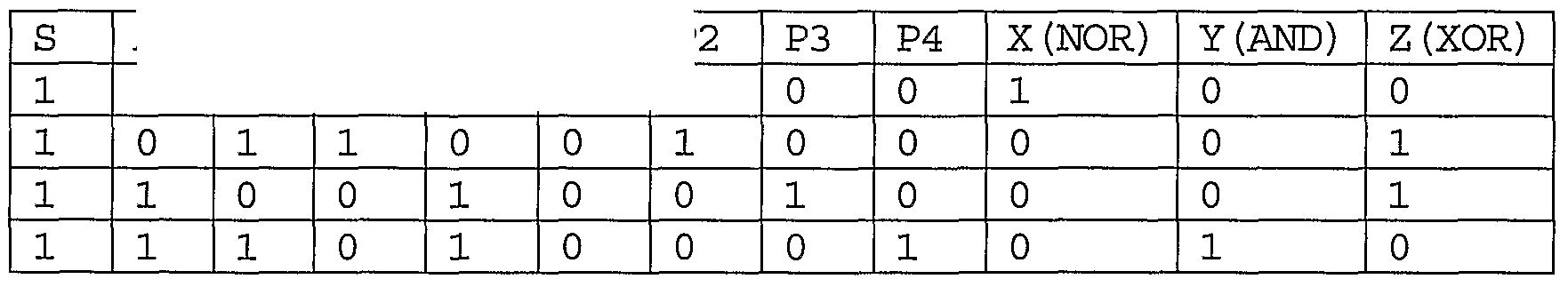
FIG. 7 shows a photon logic gate, NOR/XOR/AND. The system is composed of three quantum switches, where two of them are connected to the last one. Each output Ql (712) and Q2 (710) of the quantum switch QSl (716) are used as an input to the quantum switches QS2 (718) and QS3 (717) , respectively. The output Pl (706) is used as a logic output X. The outputs P2 and P3 are combined together (719) to lead the logic output Z (707) . The output P4 (708) is used as a logic output Y. There are two logic inputs A (702) and B (704, 715), where A is for the QSl and B is for bot QS3. The functions of R (711, 713, 709) and C ( 714) are the same as discussed above. As seen in the two logic inputs A and B performs Boolean alget the output X, XOR at Z, and AND at Y, simultaneously.