WO2008027555A2 - Method for circulating selected heat transfer fluids through a closed loop cycle - Google Patents
Method for circulating selected heat transfer fluids through a closed loop cycle Download PDFInfo
- Publication number
- WO2008027555A2 WO2008027555A2 PCT/US2007/019205 US2007019205W WO2008027555A2 WO 2008027555 A2 WO2008027555 A2 WO 2008027555A2 US 2007019205 W US2007019205 W US 2007019205W WO 2008027555 A2 WO2008027555 A2 WO 2008027555A2
- Authority
- WO
- WIPO (PCT)
- Prior art keywords
- hfc
- layer
- heat transfer
- transfer fluid
- fluid composition
- Prior art date
Links
- 0 *[C@](C(*)(*)C(C(*)(*)O1)=*)C1=O Chemical compound *[C@](C(*)(*)C(C(*)(*)O1)=*)C1=O 0.000 description 3
Classifications
-
- C—CHEMISTRY; METALLURGY
- C09—DYES; PAINTS; POLISHES; NATURAL RESINS; ADHESIVES; COMPOSITIONS NOT OTHERWISE PROVIDED FOR; APPLICATIONS OF MATERIALS NOT OTHERWISE PROVIDED FOR
- C09K—MATERIALS FOR MISCELLANEOUS APPLICATIONS, NOT PROVIDED FOR ELSEWHERE
- C09K5/00—Heat-transfer, heat-exchange or heat-storage materials, e.g. refrigerants; Materials for the production of heat or cold by chemical reactions other than by combustion
- C09K5/02—Materials undergoing a change of physical state when used
- C09K5/04—Materials undergoing a change of physical state when used the change of state being from liquid to vapour or vice versa
- C09K5/041—Materials undergoing a change of physical state when used the change of state being from liquid to vapour or vice versa for compression-type refrigeration systems
- C09K5/044—Materials undergoing a change of physical state when used the change of state being from liquid to vapour or vice versa for compression-type refrigeration systems comprising halogenated compounds
- C09K5/045—Materials undergoing a change of physical state when used the change of state being from liquid to vapour or vice versa for compression-type refrigeration systems comprising halogenated compounds containing only fluorine as halogen
-
- F—MECHANICAL ENGINEERING; LIGHTING; HEATING; WEAPONS; BLASTING
- F15—FLUID-PRESSURE ACTUATORS; HYDRAULICS OR PNEUMATICS IN GENERAL
- F15D—FLUID DYNAMICS, i.e. METHODS OR MEANS FOR INFLUENCING THE FLOW OF GASES OR LIQUIDS
- F15D1/00—Influencing flow of fluids
- F15D1/02—Influencing flow of fluids in pipes or conduits
-
- C—CHEMISTRY; METALLURGY
- C09—DYES; PAINTS; POLISHES; NATURAL RESINS; ADHESIVES; COMPOSITIONS NOT OTHERWISE PROVIDED FOR; APPLICATIONS OF MATERIALS NOT OTHERWISE PROVIDED FOR
- C09K—MATERIALS FOR MISCELLANEOUS APPLICATIONS, NOT PROVIDED FOR ELSEWHERE
- C09K2205/00—Aspects relating to compounds used in compression type refrigeration systems
- C09K2205/10—Components
- C09K2205/106—Carbon dioxide
-
- C—CHEMISTRY; METALLURGY
- C09—DYES; PAINTS; POLISHES; NATURAL RESINS; ADHESIVES; COMPOSITIONS NOT OTHERWISE PROVIDED FOR; APPLICATIONS OF MATERIALS NOT OTHERWISE PROVIDED FOR
- C09K—MATERIALS FOR MISCELLANEOUS APPLICATIONS, NOT PROVIDED FOR ELSEWHERE
- C09K2205/00—Aspects relating to compounds used in compression type refrigeration systems
- C09K2205/10—Components
- C09K2205/11—Ethers
-
- C—CHEMISTRY; METALLURGY
- C09—DYES; PAINTS; POLISHES; NATURAL RESINS; ADHESIVES; COMPOSITIONS NOT OTHERWISE PROVIDED FOR; APPLICATIONS OF MATERIALS NOT OTHERWISE PROVIDED FOR
- C09K—MATERIALS FOR MISCELLANEOUS APPLICATIONS, NOT PROVIDED FOR ELSEWHERE
- C09K2205/00—Aspects relating to compounds used in compression type refrigeration systems
- C09K2205/10—Components
- C09K2205/12—Hydrocarbons
- C09K2205/122—Halogenated hydrocarbons
-
- C—CHEMISTRY; METALLURGY
- C09—DYES; PAINTS; POLISHES; NATURAL RESINS; ADHESIVES; COMPOSITIONS NOT OTHERWISE PROVIDED FOR; APPLICATIONS OF MATERIALS NOT OTHERWISE PROVIDED FOR
- C09K—MATERIALS FOR MISCELLANEOUS APPLICATIONS, NOT PROVIDED FOR ELSEWHERE
- C09K2205/00—Aspects relating to compounds used in compression type refrigeration systems
- C09K2205/10—Components
- C09K2205/12—Hydrocarbons
- C09K2205/126—Unsaturated fluorinated hydrocarbons
-
- C—CHEMISTRY; METALLURGY
- C09—DYES; PAINTS; POLISHES; NATURAL RESINS; ADHESIVES; COMPOSITIONS NOT OTHERWISE PROVIDED FOR; APPLICATIONS OF MATERIALS NOT OTHERWISE PROVIDED FOR
- C09K—MATERIALS FOR MISCELLANEOUS APPLICATIONS, NOT PROVIDED FOR ELSEWHERE
- C09K2205/00—Aspects relating to compounds used in compression type refrigeration systems
- C09K2205/10—Components
- C09K2205/134—Components containing sulfur
Definitions
- the present invention relates to the use of flexible hoses capable of handling high pressure fluids and providing a barrier against permeation loss in air conditioning and refrigeration systems. More particularly, the present invention relates to the use of such hoses in air conditioning and refrigeration systems, including mobile air conditioning systems, in which new, low global warming potential (GWP) refrigerant alternatives are used.
- GWP global warming potential
- HFC-134a Currently proposed replacement refrigerants for HFC-134a include HFC-152a, pure hydrocarbons such as butane or propane, or "natural" refrigerants such as CO 2 or ammonia. Many of these suggested replacements are toxic, flammable, and/or have low energy efficiency. Therefore, new alternatives are constantly being sought.
- heat transfer fluids are circulated within a closed loop including a compressor, a condenser and an evaporator.
- Hoses are typically connected between the outlet of the compressor and the inlet of the condenser; between the outlet of the condenser and the inlet of the evaporator; and between the outlet of the evaporator and the inlet of the compressor.
- Such hoses must be able to withstand the high pressure of the fluids which are circulated through such systems.
- Hoses used for these purposes need to be flexible for ease of installation and use, and often must be shaped into curves and bends for connecting components already installed into fixed positions. They must also be able to contain the fluid pressure. These hoses are often made of elastomeric materials such as natural or synthetic rubber or thermoplastic elastomers, and are typically reinforced with braiding to impart high pressure capability. Moreover, it is essential that the hoses of such systems offer superior barrier resistance to permeation of the contained fluid through the wall of the hose construction. In addition, the hose wall must provide high barrier resistance to ingression of external fluids, such as air or moisture, into the contained fluid. In order to meet barrier requirements, hoses are often provided with a suitable thermoplastic barrier layer on the inside.
- a typical high pressure barrier hose may thus consist of multiple layers - an inner thermoplastic barrier layer made of a polyamide, a polyester or a suitable thermoplastic material; an over-layer of an elastomeric material to provide flexibility; and a braid layer over the elastomeric layer to provide pressure capability and an outer protective cover layer of an elastomeric material.
- Attempts to make flexible high pressure high barrier hoses often involve first making a corrugated metallic tube and coating the tube with an elastomeric polymer. Such constructions, however, require complex manufacturing processes, and are expensive for large scale uses.
- US Patent No. 7,055,553 describes a fluid transfer hose incorporating a metal barrier layer. The metal barrier layer is bonded using techniques that require use of aggressive chemicals. Also, expensive fluoropolymer layers are incorporated in the hose construction.
- hoses provide pressure capability and flexibility, their barrier properties can be improved. With the drive for reduced emissions, this becomes an issue in highly demanding applications such as refrigeration and air conditioning.
- low GWP refrigerants are developed it is important to identify barrier hoses which are suitable for these refrigerants. It would be desirable to provide a flexible hose for air conditioning or refrigeration systems which is suitable for use with new, high-pressure, low GWP refrigerants. Ideally, such a hose would not require the use of aggressive chemicals, would be economical to make, and would meet stringent barrier requirements.
- the present invention relates to transporting a heat transfer fluid within a refrigeration or air conditioning system through a hose, where the hose is able to withstand high-pressure refrigerants, and the hose has improved barrier properties.
- a further advantage of such hose is its simple and straightforward construction.
- such hose is especially suitable for use with fluoroolefin compositions which are low GWP refrigerant alternatives.
- a method of providing transport of a heat transfer fluid composition within a refrigeration or air conditioning system comprising circulating the heat transfer fluid through one or more hoses of said system, wherein said heat transfer fluid comprises a compound selected from the group consisting of: R32, R152a, CF 3 I, 1234yf, 1225ye and trans- 1234ze.
- the composition comprises 1225ye and at least one additional compound selected from the group consisting of HFC-1234ze, HFC-1234yf, HFC-1234ye, HFC-1243zf, HFC-32, HFC-125, HFC-134, HFC-134a, HFC-143a, HFC-152a, HFC-161 , HFC-227ea, HFC- 236ea, HFC-236fa, HFC-245fa, HFC-365mfc, propane, n-butane, isobutane, 2-methylbutane, n-pentane, cyclopentane, dimethylether, CF 3 SCF 3 , CO 2 , NH 3 , and CF 3 I.
- the composition comprises HFC- 1234ze and at least one additional compound selected from the group consisting of HFC-1234yf, HFC-1234ye, HFC-1243zf, HFC-32, HFC-125, HFC-134, HFC-134a, HFC-143a, HFC-152a, HFC-161 , HFC-227ea, HFC- 236ea, HFC-236fa, HFC-245fa, HFC-365mfc, propane, n-butane, isobutane, 2-methylbutane, n-pentane, cyclopentane, dimethylether, CF 3 SCF 3 , CO 2 and CF 3 I.
- the composition comprises
- HFC-1234yf and at least one additional compound selected from the group consisting of HFC-1234ye, HFC-1243zf, HFC-32, HFC-125, HFC-134, HFC-134a, HFC-143a, HFC-152a, HFC-161 , HFC-227ea, HFC-236ea, HFC-236fa, HFC-245fa, HFC-365mfc, propane, n-butane, isobutane, 2- methylbutane, n-pentane, cyclopentane, dimethylether, CF 3 SCF 3 , CO 2 , NH 3 , and CF 3 I.
- the composition comprises HFC-1243zf and at least one additional compound selected from the group consisting of HFC-1234ye, HFC-32, HFC-125, HFC-134, HFC-134a, HFC- 143a, HFC-152a, HFC-161 , HFC-227ea, HFC-236ea, HFC-236fa, HFC- 245fa, HFC-365mfc, propane, n-butane, isobutane, 2-methylbutane, n- pentane, cyclopentane, dimethylether, CF 3 SCF 3 , CO 2 and CF 3 I.
- the composition comprises HFC-1234ye and at least one additional compound selected from the group consisting of HFC-1243zf, HFC-32, HFC-125, HFC-134, HFC-134a, HFC-143a, HFC-152a, HFC-161 , HFC-227ea, HFC-236ea, HFC-236fa, HFC-245fa, HFC-365mfc, propane, n-butane, isobutane, 2-methylbutane, n-pentane, cyclopentane, dimethylether, CF 3 SCF 3 , CO 2 and CF 3 I.
- the hose comprises an outer layer comprising a material selected from the group consisting of an elastomer and a polyamide and an inner layer comprising a material selected from the group consisting of an elastomer, a polyamide and a thermoplastic.
- the hose may further include (a) a tie layer positioned over said inner layer; (b) a metal-polymer laminate positioned over said tie layer and consisting of a layer of polymer compatible with or bondable to said outer surface of said veneer, a thin layer of metallic foil, and another layer of a polymer protecting the metallic foil; (c) a braid under-layer positioned over said metal-polymer laminate and consisting of an elastomeric material; and (d) a reinforcing braid layer positioned over said braid under-layer, wherein the outer layer is positioned on the outside of the reinforcing braid layer.
- FIG.1 is a schematic diagram of a refrigeration or air conditioning system including a plurality of hoses according to the present invention.
- FIG. 2 is a cross-sectional view of a hose of the present invention.
- a refrigeration or air-conditioning system Such a system, which is a vapor compression system, is shown in Fig. 1.
- a vapor-compression system is a closed loop system which re-uses refrigerant in multiple steps producing a cooling effect in one step and a heating effect in a different step.
- Such a system generally includes an evaporator, a compressor, a condenser and an expansion device, as will be described below in detail with respect to Fig. 1.
- gaseous refrigerant from an evaporator (42) flows through a hose (63) to the inlet of a compressor (12), and is then discharged.
- compressors may be used with the present invention, including reciprocating, rotary, jet, centrifugal, scroll, screw or axial-flow, depending on the mechanical means to compress the fluid, or as positive-displacement (e.g., reciprocating, scroll or screw) or dynamic (e.g., centrifugal or jet).
- positive-displacement e.g., reciprocating, scroll or screw
- dynamic e.g., centrifugal or jet
- the compressed refrigerant gas from the compressor flows through the compressor outlet and through a hose (61) to a condenser (41).
- a pressure regulating valve (51) in hose (61) may be used. This valve allows recycle of the refrigerant flow back to the compressor via a hose (63), thereby providing the ability to control the pressure of the refrigerant reaching the condenser (41) and if necessary to prevent compressor surge.
- the compressed refrigerant is condensed in the condenser, thus giving off heat.
- the liquid refrigerant flows through an expansion device (52) via a hose (62) to the evaporator (42), which is located in the passenger compartment. In the evaporator, the liquid refrigerant is vaporized, providing cooling and the cycle then repeats.
- the expansion device (52) may be an expansion valve, a capillary tube or an orifice tube.
- the closed loop, vapor compression system of the present invention may be used in either stationary or mobile refrigeration or air- conditioning applications.
- Stationary refrigeration apparatus or stationary air-conditioning apparatus refer to the equipment used for cooling the air in a building, or cooling perishable goods such as foods, pharmaceutical materials, etc, in a conventional, non-mobile, non-vehicle mounted system. These systems may include chillers, ducted and ductless air conditioners and heat pumps, domestic refrigerators and freezers, commercial refrigerators and freezers, supermarket and industrial refrigeration systems.
- Such stationary refrigeration or air conditioning systems may be associated with CHP (Combined Heat and Power) systems, wherein a stationary internal combustion engine is used to drive an electrical generator.
- CHP Combined Heat and Power
- the waste heat produced by the engine may be recovered and used to perform work, by such means as a Rankine Cycle (steam engine) or Organic Rankine cycle (ORC).
- a Rankine cycle the heat is used to vaporize a liquid (an organic liquid in the case of an ORC), which in turn drives a turbine.
- the mechanical energy of the turbine may be used to drive an electricity generator, which runs a refrigeration or air-conditioning system.
- Mobile refrigeration apparatus or mobile air-conditioning apparatus refers to any refrigeration or air-conditioning apparatus incorporated into a mobile transportation unit for the road, rail, sea or air.
- apparatus which are meant to provide refrigeration or air-conditioning for a system independent of any moving carrier, known as “intermodal" systems, are included in the present invention.
- intermodal systems include “containers” (combined sea/land transport) as well as “swap bodies” (combined road and rail transport).
- the present invention is particularly useful for road transport refrigerating or air-conditioning apparatus, such as automobile air-conditioning apparatus or refrigerated road transport equipment.
- a body to be cooled may be any space, location or object requiring refrigeration or air-conditioning.
- the body may be the interior of a structure, i.e. residential or commercial, or a storage location for perishables, such as food or pharmaceuticals. Numerous mobile systems are described earlier in defining mobile refrigeration apparatus and mobile air-conditioning apparatus.
- the refrigeration apparatus or air-conditioning apparatus of the present invention may additionally employ fin and tube heat exchangers, microchannel heat exchangers and vertical or horizontal single pass tube or plate type heat exchangers in the evaporator and/or the condenser.
- a method of providing transport of a heat transfer fluid within a refrigeration or air conditioning system comprising circulating a heat transfer fluid composition through one or more hoses of said system.
- the hose may comprise an outer layer comprising a material selected from the group consisting of an elastomer and a polyamide.
- the hose may further comprise an inner layer comprising a material selected from the group consisting of an elastomer, a polyamide and a thermoplastic.
- the inner layer may comprise a thermoplastic veneer
- the outer layer may comprise an elastomer.
- hoses are constructed in multiple layers such as described below from the innermost to the outermost surface, including: - an layer of a thermoplastic veneer;
- - a metal-polymer laminate consisting of a layer of polymer compatible with the tie layer, a thin layer of metallic foil, and another layer of a polymer protecting the metallic foil; - a braid under-layer of a thermoplastic or thermosetting elastomer;
- FIG. 2 there is shown generally at 10 each of the layers of the invention, numbered and described from the innermost layer to the outermost layer.
- a thermoplastic veneer 12 having an inner surface 14 and an outer surface 16.
- the veneer may incorporate a tie layer 18 positioned at its outer surface 16.
- a metal-polymer laminate 20 is positioned over the tie layer and consisting of a layer 22 of polymer compatible with or bondable to the outer surface of the veneer, a thin layer 24 of metallic foil, and another layer 26 of a polymer protecting the metallic foil.
- a braid under-layer 28 is positioned over the metal-polymer laminate 20 and consisting of an elastomeric material.
- a reinforcing braid layer 30 is then positioned over the braid under-layer 28.
- an outer layer 32 of an elastomeric material positioned over the reinforcing braid layer 30.
- the hose of this one embodiment of the present invention is manufactured in multiple steps, sequenced as provided below.
- mandrels are commonly used in the manufacture of hoses made out of thermosetting materials that need to be supported during the extrusion and curing steps. They are made of a variety of thermoplastic or thermosetting materials such as copolyester ethers, copolyamides, polyolefins, TPVs, EPDMs, synthetic rubbers etc. It is desirable to ensure that the mandrel has sufficient flexibility to be spoolable in long lengths.
- Step 2 - A thermoplastic veneer is extruded over the mandrel.
- the veneer can be in the form of a monolayer or a two layer tube depending on the type of metal foil and polymer laminate to be used in step 3 as explained below. It should not develop adhesion to the mandrel surface so that mandrel can be extracted at the end of hose fabrication. As appropriate, one of skill in the field can apply suitable release agents to the mandrel to facilitate the nonadhesive properties of the mandrel in relation to the inner layer of the veneer and lubricate its extraction at the end of hose fabrication.
- a monolayer veneer or the inner layer of the two-layer veneer can be made of a polyamide, copolyamide, polyphthalamide, polyester or copolyester that provides chemical and thermal resistance to the contained fluid it is in contact with.
- the laminate used in step 3 is provided with an adhesive that can bond to the surface of the veneer.
- Such laminates are those where metallic foil is laminated with a pressure sensitive adhesive (PSA) that can adhere to the surface of the veneer.
- PSA pressure sensitive adhesive
- Such laminates are available commercially with variety of adhesives such as acrylics, rubber, silicones etc.
- the outer layer is made of a functionalized polymer to function as a tie layer between the inner thermoplastic veneer and the metal-polymer laminate to be provided over it.
- a functionalized polyolefin or copolyolefin such as those made by grafting or copolymerizing functional monomers with olefins and copolyolefins.
- functional monomers include those with acid, anhydride, acrylate, epoxy functionality.
- Step 3 A metal foil and polymer laminate consisting of a first polymer layer compatible or bondable to the surface of the veneer, a thin metallic foil and a second polymer layer (which may be identical to or different from the first polymer layer) is then applied over the assembly prepared in step 2.
- Adhesion can be further promoted by application of heat and/or pressure as warranted. Heating may not be necessary if the first polymer layer of the laminate is a room temperature pressure sensitive adhesive (PSA) type.
- PSA room temperature pressure sensitive adhesive
- the assembly of Step 2 is covered by the metal foil laminate and passed through a heated die designed to apply pressure on to the assembly to form the bonding.
- the veneer supported by the mandrel is first passed through a heating tunnel so as to raise the surface temperature of the veneer. The metal foil laminate is then applied over the veneer, and the assembly is passed through another heated die designed to apply pressure and affect bonding.
- the laminate is applied over the veneer lengthwise so that it circumferentially wraps around it.
- the two edges of the foil positioned lengthwise along the tube are bonded tightly together and any excess foil is then trimmed to provide a fully covered assembly.
- This form of wrapping is preferred over the so-called helical wrap formed by winding a tape over the veneer in a helical fashion at an angle to the axis of the hose because it results in only one seam running along the length of the hose. From barrier perspective, a seam can provide potential site for permeation leak. Hence, it is desirable to minimize it's occurrence in the construction. Lengthwise wrap described above is also easier to apply especially on a small diameter tubing such as that encountered in flexible high pressure hoses.
- Metallic foil is thin enough to provide flexibility while resist fracture during handling.
- it can be aluminum foil, in 1-10 micron thickness range to provide very high level of barrier while retaining flexibility. Note that this approach provides a continuous layer of metal over the tube surface unlike vapor deposition techniques which leave gaps in metal coverage resulting in inferior barrier properties.
- the second layer of polymer over the metallic foil is selected to protect the surface of the metal foil and provide compatibility with the braid under-layer to be provided over it. It can be a polyamide, polyester or a polyolefin, and is selected so as to be compatible with the type of braid underlayer to be used in the next step.
- Step 4 - A braid underlayer is extruded over the assembly of Step
- the underlayer is an elastomeric material such as a natural or synthetic rubber or a thermoplastic elastomer such as thermoplastic olefin (TPO), thermoplastic ester elastomer (TEE) or a thermoplastic vulcanizate (such as ETPV or TPV, common selections in this field). Its purpose is to provide cushioning and protection against forces imposed during braiding.
- a thermoplastic elastomer such as thermoplastic olefin (TPO), thermoplastic ester elastomer (TEE) or a thermoplastic vulcanizate (such as ETPV or TPV, common selections in this field). Its purpose is to provide cushioning and protection against forces imposed during braiding.
- this braid underlayer bonds to the surface of the laminate applied in step 3. This may be accomplished by several means such as ensuring that the braid underlayer material is compatible with the surface layer of the laminate, extruding a two-layer braid underlayer such that its inner layer acts as a tie layer to bond to the surface of the laminate or sequentially extruding a tie layer over the laminate first and then the braid underlayer.
- a functionalized polymer such as that used for forming the tie layer of the two-layer veneer of step 2 may be used for this purpose, the functionalization chosen to be compatible with the two layers to be bonded.
- Step 5 - A braided reinforcement layer is provided over the assembly of Step 4.
- braiding can be made of metallic or polymeric filaments or high performance filaments such as Kevlar ® or Nomex ® , both commercially available from E.I. du Pont de Nemours and Company of Wilmington, Delaware. Braid density is determined according to desired pressure capability and filament material selection. Multiple layers of braid and hybrid braids of multiple types of filaments are often used in practice to maximize the degree of reinforcement while optimizing the cost.
- Step 6 An outer protective layer is extruded over the braided reinforcement layer.
- This layer can again be made of an elastomeric material such as TPO, TEE or a thermoplastic vulcanizate (ETPV or TPV).
- Step 7 If any of the layers in the hose construction are made of a thermosetting material, then the assembly of Step 6 needs to cure. If all the layers are made of thermoplastic materials, then curing is not necessary. Note that one or more outer protective layers can be added at this time as well.
- Step 8 the mandrel is extracted from the assembly of Step 6 or Step 7 to produce the finished hose.
- the mandrel can be extracted by applying hydraulic pressure to one end of the hose or by mechanical means.
- Hose made this way can be cut to desired length and fittings can be applied as desired.
- the hose made this way provides flexibility, high pressure capability and very high barrier capability.
- the heat transfer fluid composition comprises a compound selected from the group consisting of: R32, R152a, CF 3 I, 1234yf, 1225ye and trans-1234ze.
- the heat transfer fluid composition comprises at least one fluoroolefin.
- the heat transfer fluid compositions of the present invention may further comprise at least one additional component that may be a second fluoroolefin, hydrofluorocarbon (HFC), hydrocarbon, dimethyl ether, bis(trifluoromethyl)sulfide, CF 3 I, or CO 2 .
- the heat transfer fluid composition comprises 1225ye and at least one additional compound selected from the group consisting of HFC-1234ze, HFC-1234yf, HFC-1234ye, HFC-1243zf, HFC-32, HFC-125, HFC-134, HFC-134a, HFC-143a, HFC-152a, HFC-161 , HFC-227ea, HFC-236ea, HFC-236fa, HFC-245fa, HFC-365mfc, propane, n-butane, isobutane, 2- methylbutane, n-pentane, cyclopentane, dimethylether, CF 3 SCF 3 , CO 2 , NH 3 , and CF 3 I.
- the heat transfer fluid composition comprises HFC-1234ze and at least one additional compound selected from the group consisting of HFC-1234yf, HFC-1234ye, HFC-1243zf, HFC-32, HFC-125, HFC-134, HFC-134a, HFC-143a, HFC-152a, HFC-161 , HFC-227ea, HFC-236ea, HFC-236fa, HFC-245fa, HFC-365mfc, propane, n-butane, isobutane, 2- methylbutane, n-pentane, cyclopentane, dimethylether, CF 3 SCF 3 , CO2 and CF 3 I.
- the heat transfer fluid composition comprises HFC-1234yf and at least one additional compound selected from the group consisting of HFC-1234ye, HFC-1243zf, HFC-32, HFC-125, HFC-134, HFC-134a, HFC-143a, HFC- 152a, HFC-161 , HFC-227ea, HFC-236ea, HFC-236fa, HFC-245fa, HFC- 365mfc, propane, n-butane, isobutane, 2-methylbutane, n-pentane, cyclopentane, dimethylether, CF3sCF 3 , CO 2 , NH 3 , and CF 3 I.
- the heat transfer fluid composition comprises HFC-1243zf and at least one additional compound selected from the group consisting of HFC-1234ye, HFC-32, HFC-125, HFC-134, HFC-134a, HFC-143a, HFC-152a, HFC-161 , HFC-227ea, HFC-236ea, HFC-236fa, HFC-245fa, HFC-365mfc, propane, n-butane, isobutane, 2-methylbutane, n-pentane, cyclopentane, dimethylether, CF 3 SCF 3 , CO 2 and CF 3 I.
- the heat transfer fluid composition comprises HFC-1234ye and at least one additional compound selected from the group consisting of HFC-1243zf, HFC-32, HFC-125, HFC-134, HFC-134a, HFC-143a, HFC-152a, HFC- 161 , HFC-227ea, HFC-236ea, HFC-236fa, HFC-245fa, HFC-365mfc, propane, n-butane, isobutane, 2-methylbutane, n-pentane, cyclopentane, dimethylether, CF 3 SCF 3 , CO 2 and CF 3 I.
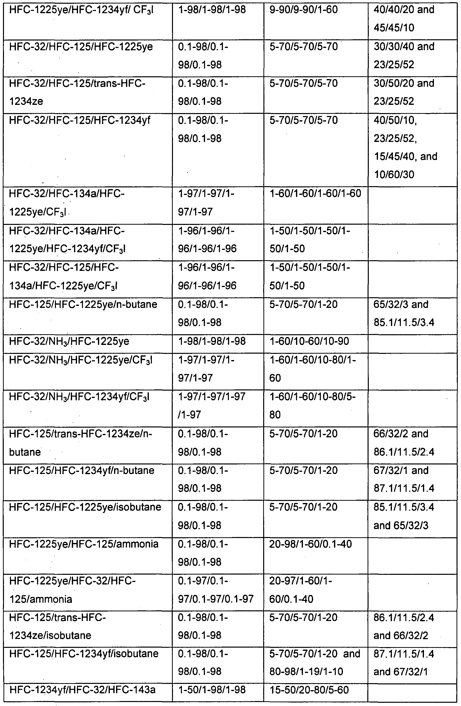
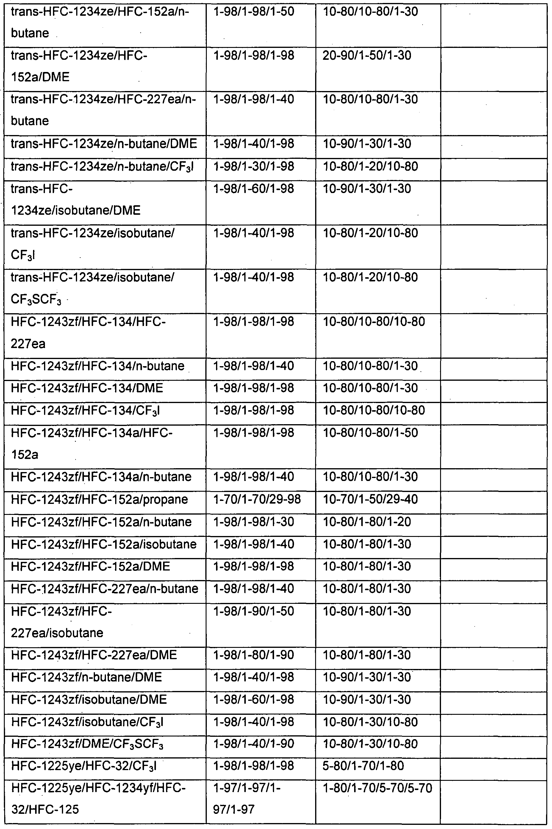
- the fluoroolefin and the other components of the heat transfer fluid compositions of the present invention are listed in Table 1.
- the fluoroolefin compounds used in the compositions of the present invention may exist as different configurational isomers or stereoisomers.
- the present invention is intended to include all single configurational isomers, single stereoisomers or any combination or mixture thereof.
- 1 ,3,3,3-tetra-fluoropropene (HFC-1234ze) is meant to represent the cis- isomer, trans-isomer, or any combination or mixture of both isomers in any ratio.
- HFC-1225ye by which is represented the cis- isomer, trans-isomer, or any combination or mixture of both isomers in any ratio.
- the compositions of the present invention contain primarily the cis or Z isomer of HFC-1225ye.
- the heat transfer fluid compositions of the present invention may be generally useful when the fluoroolefin is present at about 1 weight percent to about 99 weight percent, preferably about 20 weight percent to about 99 weight percent, more preferably about 40 weight percent to about 99 weight percent and still more preferably 50 weight percent to about 99 weight percent.
- the present invention further provides compositions as listed in Table 2.
- compositions of the present invention listed in Table 2 are generally expected to maintain the desired properties and functionality when the components are present in the concentrations as listed +/- 2 weight percent.
- compositions containing CO 2 would be expected to maintain the desired properties and functionality when the CO 2 was present at the listed concentration +/- 0.2 weight percent.
- compositions of the present invention may be azeotropic or near-azeotropic compositions.
- azeotropic composition is meant a constant-boiling mixture of two or more substances that behave as a single substance.
- One way to characterize an azeotropic composition is that the vapor produced by partial evaporation or distillation of the liquid has the same composition as the liquid from which it is evaporated or distilled, i.e., the mixture distills/refluxes without compositional change.
- Constant-boiling compositions are characterized as azeotropic because they exhibit either a maximum or minimum boiling point, as compared with that of the non-azeotropic mixture of the same compounds.
- An azeotropic composition will not fractionate within a refrigeration or air conditioning system during operation, which may reduce efficiency of the system. Additionally, an azeotropic composition will not fractionate upon leakage from a refrigeration or air conditioning system. In the situation where one component of a mixture is flammable, fractionation during leakage could lead to a flammable composition either within the system or outside of the system.
- a near-azeotropic composition (also commonly referred to as an "azeotrope-like composition”) is a substantially constant boiling liquid admixture of two or more substances that behaves essentially as a single substance.
- a near-azeotropic composition One way to characterize a near-azeotropic composition is that the vapor produced by partial evaporation or distillation of the liquid has substantially the same composition as the liquid from which it was evaporated or distilled, that is, the admixture distills/refluxes without substantial composition change.
- Another way to characterize a near- azeotropic composition is that the bubble point vapor pressure and the dew point vapor pressure of the composition at a particular temperature are substantially the same.
- a composition is near-azeotropic if, after 50 weight percent of the composition is removed, such as by evaporation or boiling off, the difference in vapor pressure between the original composition and the composition remaining after 50 weight percent of the original composition has been removed is less than about 10 percent.
- ternary azeotropes composition have been found as listed in Table 4.
- compositions of the present invention are non- azeotropic compositions. Those compositions of the present invention falling within the preferred ranges of Table 2, but outside of the near- azeotropic ranges of Table 5 and Table 6 may be considered to be non- azeotropic.
- a non-azeotropic composition may have certain advantages over azeotropic or near azeotropic mixtures.
- a non-azeotropic composition is a mixture of two or more substances that behaves as a mixture rather than a single substance.
- One way to characterize a non-azeotropic composition is that the vapor produced by partial evaporation or distillation of the liquid has a substantially different composition as the liquid from which it was evaporated or distilled, that is, the admixture distills/refluxes with substantial composition change.
- Another way to characterize a non- azeotropic composition is that the bubble point vapor pressure and the dew point vapor pressure of the composition at a particular temperature are substantially different.
- compositions of the present invention may be prepared by any convenient method to combine the desired amounts of the individual components. A preferred method is to weigh the desired component amounts and thereafter combine the components in an appropriate vessel. Agitation may be used, if desired.
- An alternative means for making compositions of the present invention may be a method for making a refrigerant blend composition, wherein said refrigerant blend composition comprises a composition as disclosed herein, said method comprising (i) reclaiming a volume of one or more components of a refrigerant composition from at least one refrigerant container, (ii) removing impurities sufficiently to enable reuse of said one or more of the reclaimed components, (iii) and optionally, combining all or part of said reclaimed volume of components with at least one additional refrigerant composition or component.
- a refrigerant container may be any container in which is stored a refrigerant blend composition that has been used in a refrigeration apparatus, air-conditioning apparatus or heat pump apparatus.
- Said refrigerant container may be the refrigeration apparatus, air-conditioning apparatus or heat pump apparatus in which the refrigerant blend was used. Additionally, the refrigerant container may be a storage container for collecting reclaimed refrigerant blend components, including but not limited to pressurized gas cylinders.
- Residual refrigerant means any amount of refrigerant blend or refrigerant blend component that may be moved out of the refrigerant container by any method known for transferring refrigerant blends or refrigerant blend components.
- Impurities may be any component that is in the refrigerant blend or refrigerant blend component due to its use in a refrigeration apparatus, air- conditioning apparatus or heat pump apparatus.
- Such impurities include but are not limited to refrigeration lubricants, being those described earlier herein, particulates including but not limited to metal, metal salt or elastomer particles, that may have come out of the refrigeration apparatus, air-conditioning apparatus or heat pump apparatus, and any other contaminants that may adversely effect the performance of the refrigerant blend composition.
- Such impurities may be removed sufficiently to allow reuse of the refrigerant blend or refrigerant blend component without adversely effecting the performance or equipment within which the refrigerant blend or refrigerant blend component will be used.
- the heat transfer fluid compositions of the present invention will have global warming potential (GWP) that are less than many hydrofluorocarbon refrigerants currently in use. Preferably, such compositions will also have zero or low ozone depletion potential.
- GWP global warming potential
- One aspect of the present invention is to provide a refrigerant with a global warming potential of less than 1000, less than 500, less than 150, less than 100, or less than 50.
- Another aspect of the present invention is to reduce the net GWP of refrigerant mixtures by adding fluoroolefins to said mixtures.
- compositions of the present invention may be useful as low global warming potential (GWP) replacements for currently used refrigerants, including but not limited to R134a (or HFC-134a, 1 ,1 ,1 ,2- tetrafluoroethane), R22 (or HCFC-22, chlorodifluoromethane), R123 (or HFC-123, 2,2-dichloro-1 ,1 ,1-trifluoroethane), R11 (CFC-11 , fluorotrichloromethane), R12 (CFC-12, dichlorodifluoromethane), R245fa (or HFC-245fa, 1 ,1 ,1 ,3,3-pentafluoropropane), R114 (or CFC-114, 1 ,2- dichloro-1 ,1 ,2,2-tetrafluoroethane), R236fa (or HFC-236fa, 1 ,1 ,1 ,3,3,3- hexafluoro
- compositions of the present invention may be useful as replacements for R12 (CFC-12, dichlorodifluoromethane) or R502 (ASHRAE designation for a blend of 51.2 weight percent CFC-115 (chloropentafluoroethane) and 48.8 weight percent HCFC-22).
- compositions of the present invention may be useful as replacements for the above-mentioned refrigerants in original equipment. Additionally, the compositions of the present invention may be useful as replacements for the above mentioned refrigerants in equipment designed to use the above-mentioned refrigerants.
- compositions of the present invention may further comprise a lubricant.
- Lubricants of the present invention comprise refrigeration lubricants, i.e. those lubricants suitable for use with refrigeration, air- conditioning, or heat pump apparatus. Among these lubricants are those conventionally used in compression refrigeration apparatus utilizing chlorofluorocarbon refrigerants. Such lubricants and their properties are discussed in the 1990 ASHRAE Handbook, Refrigeration Systems and Applications, chapter 8, titled “Lubricants in Refrigeration Systems", pages 8.1 through 8.21. Lubricants of the present invention may comprise those commonly known as "mineral oils" in the field of compression refrigeration lubrication. Mineral oils comprise paraffins (i.e.
- Lubricants of the present invention further comprise those commonly known as "synthetic oils" in the field of compression refrigeration lubrication. Synthetic oils comprise alkylaryls (i.e. linear and branched alkyl alkylbenzenes), synthetic paraffins and napthenes, and poly(alphaolefins).
- Representative conventional lubricants of the present invention are the commercially available BVM 100 N (paraffinic mineral oil sold by BVA Oils), Suniso® 3GS and Suniso® 5GS (naphthenic mineral oil sold by Crompton Co.), Sontex® 372LT (naphthenic mineral oil sold by Pennzoil), Calumet® RO-30 (naphthenic mineral oil sold by Calumet Lubricants), Zerol® 75, Zerol® 150 and Zerol® 500 (linear alkylbenzenes sold by Scheve Chemicals) and HAB 22 (branched alkylbenzene sold by Nippon Oil).
- BVM 100 N paraffinic mineral oil sold by BVA Oils
- Suniso® 3GS and Suniso® 5GS naphthenic mineral oil sold by Crompton Co.
- Sontex® 372LT naphthenic mineral oil sold by Pennzoil
- Calumet® RO-30 naphthenic mineral oil sold by Calumet Lubricants
- Lubricants of the present invention further comprise those that have been designed for use with hydrofluorocarbon refrigerants and are miscible with refrigerants of the present invention under compression refrigeration, air-conditioning, or heat pump apparatus' operating conditions.
- Such lubricants and their properties are discussed in "Synthetic Lubricants and High-Performance Fluids", R. L. Shubkin, editor, Marcel Dekker, 1993.
- Such lubricants include, but are not limited to, polyol esters (POEs) such as Castrol® 100 (Castrol, United Kingdom), polyalkylene glycols (PAGs) such as RL-488A from Dow (Dow Chemical, Midland, Michigan), and polyvinyl ethers (PVEs). These lubricants are readily available from various commercial sources.
- Lubricants of the present invention are selected by considering a given compressor's requirements and the environment to which the lubricant will be exposed. Lubricants of the present invention preferably have a kinematic viscosity of at least about 5 cs (centistokes) at 4O 0 C.
- Commonly used refrigeration system additives may optionally be added, as desired, to compositions of the present invention in order to enhance lubricity and system stability.
- These additives are generally known within the field of refrigeration compressor lubrication, and include anti wear agents, extreme pressure lubricants, corrosion and oxidation inhibitors, metal surface deactivators, free radical scavengers, foaming and antifoam control agents, leak detectants and the like. In general, these additives are present only in small amounts relative to the overall lubricant composition. They are typically used at concentrations of from less than about 0.1 % to as much as about 3 % of each additive. These additives are selected on the basis of the individual system requirements.
- additives may include, but are not limited to, lubrication enhancing additives, such as alkyl or aryl esters of phosphoric acid and of thiophosphates.
- lubrication enhancing additives such as alkyl or aryl esters of phosphoric acid and of thiophosphates.
- the metal dialkyl dithiophosphates e.g. zinc dialkyl dithiophosphate or ZDDP, Lubrizol 1375
- Other antiwear additives include natural product oils and assymetrical polyhydroxyl lubrication additives such as Synergol TMS (International Lubricants).
- stabilizers such as anti oxidants, free radical scavengers, and water scavengers may be employed.
- Compounds in this category can include, but are not limited to, butylated hydroxy toluene (BHT) and epoxides.
- compositions of the present invention may further comprise about 0.01 weight percent to about 5 weight percent of an additive such as, for example, a stabilizer, free radical scavenger and/or antioxidant.
- an additive such as, for example, a stabilizer, free radical scavenger and/or antioxidant.
- additives include but are not limited to, nitromethane, hindered phenols, hydroxylamines, thiols, phosphites, or lactones. Single additives or combinations may be used.
- compositions of the present invention may further comprise about 0.01 weight percent to about 5 weight percent of a water scavenger (drying compound).
- a water scavenger drying compound
- Such water scavengers may comprise ortho esters such as trimethyl-, triethyl-, or tripropylortho formate.
- compositions of the present invention may further comprise a tracer selected from the group consisting of hydrofluorocarbons (HFCs), deuterated hydrocarbons, deuterated hydrofluorocarbons, perfluorocarbons, fluoroethers, brominated compounds, iodated compounds, alcohols, aldehydes, ketones, nitrous oxide (N 2 O) and combinations thereof.
- HFCs hydrofluorocarbons
- deuterated hydrocarbons deuterated hydrofluorocarbons
- perfluorocarbons perfluorocarbons
- fluoroethers brominated compounds
- iodated compounds alcohols
- aldehydes aldehydes
- ketones nitrous oxide
- N 2 O nitrous oxide
- the compounds listed in Table 7 are available commercially (from chemical supply houses) or may be prepared by processes known in the art.
- Single tracer compounds may be used in combination with the heat transfer fluid compositions of the present invention or multiple tracer compounds may be combined in any proportion to serve as a tracer blend.
- the tracer blend may contain multiple tracer compounds from the same class of compounds or multiple tracer compounds from different classes of compounds.
- a tracer blend may contain 2 or more deuterated hydrofluorocarbons, or one deuterated hydrofluorocarbon in combination with one or more perfluorocarbons.
- the tracer compound or tracer blend may be present in the compositions at a total concentration of about 50 parts per million by weight (ppm) to about 1000 ppm.
- the tracer compound or tracer blend is present at a total concentration of about 50 ppm to about 500 ppm and most preferably, the tracer compound or tracer blend is present at a total concentration of about 100 ppm to about 300 ppm.
- the compositions of the present invention may further comprise a compatibilizer selected from the group consisting of polyoxyalkylene glycol ethers, amides, nitriles, ketones, chlorocarbons, esters, lactones, aryl ethers, fluoroethers and 1 ,1 ,1-trifluoroalkanes.
- the compatibilizer is used to improve solubility of hydrofluorocarbon refrigerants in conventional refrigeration lubricants.
- Refrigeration lubricants are needed to lubricate the compressor of a refrigeration, air-conditioning or heat pump apparatus. The lubricant must move throughout the apparatus with the refrigerant in particular it must return from the non-compressor zones to the compressor to continue to function as lubricant and avoid compressor failure.
- Hydrofluorocarbon refrigerants are generally not compatible with convention refrigeration lubricants such as mineral oils, alkylbenzenes, synthetic paraffins, synthetic napthenes and poly(alpha)olefins. Many replacement lubricants have been proposed, however, the polyalkylene glycols, polyol esters and polyvinyl ethers, suggested for use with hydrofluorocarbon refrigerants are expensive and absorb water readily. Water in a refrigeration, air-conditioning system or heat pump can lead to corrosion and the formation of particles that may plug the capillary tubes and other small orifices in the system, ultimately causing system failure. Additionally, in existing equipment, time-consuming and costly flushing procedures are required to change to a new lubricant. Therefore, it is desirable to continue to use the original lubricant if possible.
- convention refrigeration lubricants such as mineral oils, alkylbenzenes, synthetic paraffins, synthetic napthenes and poly(alpha)olefins.
- Many replacement lubricants have
- the compatibilizers of the present invention improve solubility of the hydrofluorocarbon refrigerants in conventional refrigeration lubricants and thus improve oil return to the compressor.
- Polyoxyalkylene glycol ether compatibilizers of the present invention are represented by the formula R 1 [(OR 2 ) x OR 3 ] y , wherein: x is an integer from 1-3; y is an integer from 1-4; R 1 is selected from hydrogen and aliphatic hydrocarbon radicals having 1 to 6 carbon atoms and y bonding sites; R 2 is selected from aliphatic hydrocarbylene radicals having from 2 to 4 carbon atoms; R 3 is selected from hydrogen and aliphatic and alicyclic hydrocarbon radicals having from 1 to 6 carbon atoms; at least one of R 1 and R 3 is said hydrocarbon radical; and wherein said polyoxyalkylene glycol ethers have a molecular weight of from about 100 to about 300 atomic mass units.
- bonding sites mean radical sites available to form covalent bonds with other radicals.
- Hydrocarbylene radicals mean divalent hydrocarbon radicals.
- preferred polyoxyalkylene glycol ether compatibilizers are represented by R 1 [(OR 2 ) x OR 3 ] y : x is preferably 1-2; y is preferably 1 ; R 1 and R 3 are preferably independently selected from hydrogen and aliphatic hydrocarbon radicals having 1 to 4 carbon atoms; R 2 is preferably selected from aliphatic hydrocarbylene radicals having from 2 or 3 carbon atoms, most preferably 3 carbon atoms; the polyoxyalkylene glycol ether molecular weight is preferably from about 100 to about 250 atomic mass units, most preferably from about 125 to about 250 atomic mass units.
- the R 1 and R 3 hydrocarbon radicals having 1 to 6 carbon atoms may be linear, branched or cyclic.
- Representative R 1 and R 3 hydrocarbon radicals include methyl, ethyl, propyl, isopropyl, butyl, isobutyl, sec-butyl, terf-butyl, pentyl, isopentyl, neopentyl, terf-pentyl, cyclopentyl, and cyclohexyl.
- free hydroxyl radicals on the present polyoxyalkylene glycol ether compatibilizers may be incompatible with certain compression refrigeration apparatus materials of construction (e.g.
- R 1 and R 3 are preferably aliphatic hydrocarbon radicals having 1 to 4 carbon atoms, most preferably 1 carbon atom.
- the R 2 aliphatic hydrocarbylene radicals having from 2 to 4 carbon atoms form repeating oxyalkylene radicals - (OR 2 ) X - that include oxyethylene radicals, oxypropylene radicals, and oxybutylene radicals.
- the oxyalkylene radical comprising R 2 in one polyoxyalkylene glycol ether compatibilizer molecule may be the same, or one molecule may contain different R 2 oxyalkylene groups.
- the present polyoxyalkylene glycol ether compatibilizers preferably comprise at least one oxypropylene radical.
- R 1 is an aliphatic or alicyclic hydrocarbon radical having 1 to 6 carbon atoms and y bonding sites
- the radical may be linear, branched or cyclic.
- Representative R 1 aliphatic hydrocarbon radicals having two bonding sites include, for example, an ethylene radical, a propylene radical, a butylene radical, a pentylene radical, a hexylene radical, a cyclopentylene radical and a cyclohexylene radical.
- R 1 aliphatic hydrocarbon radicals having three or four bonding sites include residues derived from polyalcohols, such as trimethylolpropane, glycerin, pentaerythritol, 1 ,2,3-trihyclroxycyclohexane and 1,3,5- trihydroxycyclohexane, by removing their hydroxyl radicals.
- Representative polyoxyalkylene glycol ether compatibilizers include but are not limited to: CH 3 OCH 2 CH(CH 3 )O(H or CH 3 ) (propylene glycol methyl (or dimethyl) ether), CH 3 O[CH 2 CH(CH 3 )O] 2 (H or CH 3 ) (dipropylene glycol methyl (or dimethyl) ether), CH 3 O[CH 2 CH(CH 3 )O] 3 (H or CH 3 ) (tripropylene glycol methyl (or dimethyl) ether), C 2 H 5 OCH 2 CH(CH 3 )O(H or C 2 H 5 ) (propylene glycol ethyl (or diethyl) ether), C 2 H 5 O[CH 2 CH(CH 3 )O] 2 (H or C 2 H 5 ) (dipropylene glycol ethyl (or diethyl) ether), C 2 H 5 O[CH 2 CH(CH 3 )O] 3 (H or C 2 H 5 ) (
- Amide compatibilizers of the present invention comprise those represented by the formulae R 1 C(O)NR 2 R 3 and cyclo-[R 4 C(O)N(R 5 )], wherein R 1 , R 2 , R 3 and R 5 are independently selected from aliphatic and alicyclic hydrocarbon radicals having from 1 to 12 carbon atoms; R 4 is selected from aliphatic hydrocarbylene radicals having from 3 to 12 carbon atoms; and wherein said amides have a molecular weight of from about 100 to about 300 atomic mass units. The molecular weight of said amides is preferably from about 160 to about 250 atomic mass units.
- R 1 , R 2 , R 3 and R 5 may optionally include substituted hydrocarbon radicals, that is, radicals containing non-hydrocarbon substituents selected from halogens (e.g., fluorine, chlorine) and alkoxides (e.g. methoxy).
- R 1 , R 2 , R 3 and R 5 may optionally include heteroatom-substituted hydrocarbon radicals, that is, radicals, which contain the atoms nitrogen (aza-), oxygen (oxa-) or sulfur (thia-) in a radical chain otherwise composed of carbon atoms.
- amide compatibilizers consist of carbon, hydrogen, nitrogen and oxygen.
- R 1 , R 2 , R 3 and R 5 aliphatic and alicyclic hydrocarbon radicals include methyl, ethyl, propyl, isopropyl, butyl, isobutyl, sec-butyl, te/f-butyl, pentyl, isopentyl, neopentyl, terf-pentyl, cyclopentyl, cyclohexyl, heptyl, octyl, nonyl, decyl, undecyl, dodecyl and their configurational isomers.
- a preferred embodiment of amide compatibilizers are those wherein R 4 in the aforementioned formula cyclo-[R 4 C(O)N(R 5 )-] may be represented by the hydrocarbylene radical (CR 6 R 7 ) n , in other words, the formula: cyclo-[(CR 6 R 7 ) n C(O)N(R 5 )-] wherein: the previously-stated values for molecular weight apply; n is an integer from 3 to 5; R 5 is a saturated hydrocarbon radical containing 1 to 12 carbon atoms; R 6 and R 7 are independently selected (for each n) by the rules previously offered defining R 1"3 .
- lactams represented by the formula: cyclo-
- R 6 and R 7 are preferably hydrogen, or contain a single saturated hydrocarbon radical among the n methylene units, and R 5 is a saturated hydrocarbon radical containing 3 to 12 carbon atoms.
- R 5 is a saturated hydrocarbon radical containing 3 to 12 carbon atoms.
- Representative amide compatibilizers include but are not limited to:
- Ketone compatibilizers of the present invention comprise ketones represented by the formula R 1 C(O)R 2 , wherein R 1 and R 2 are independently selected from aliphatic, alicyclic and aryl hydrocarbon radicals having from 1 to 12 carbon atoms, and wherein said ketones have a molecular weight of from about 70 to about 300 atomic mass units.
- R 1 and R 2 in said ketones are preferably independently selected from aliphatic and alicyclic hydrocarbon radicals having 1 to 9 carbon atoms.
- the molecular weight of said ketones is preferably from about 100 to 200 atomic mass units.
- R 1 and R 2 may together form a hydrocarbylene radical connected and forming a five, six, or seven-membered ring cyclic ketone, for example, cyclopentanone, cyclohexanone, and cycloheptanone.
- R 1 and R 2 may optionally include substituted hydrocarbon radicals, that is, radicals containing non-hydrocarbon substituents selected from halogens (e.g., fluorine, chlorine) and alkoxides (e.g. methoxy).
- R 1 and R 2 may optionally include heteroatom-substituted hydrocarbon radicals, that is, radicals, which contain the atoms nitrogen (aza-), oxygen (keto-, oxa-) or sulfur (thia-) in a radical chain otherwise composed of carbon atoms.
- heteroatom-substituted hydrocarbon radicals that is, radicals, which contain the atoms nitrogen (aza-), oxygen (keto-, oxa-) or sulfur (thia-) in a radical chain otherwise composed of carbon atoms.
- no more than three non-hydrocarbon substituents and heteroatoms, and preferably no more than one, will be present for each 10 carbon atoms in R 1 and R 2 , and the presence of any such non- hydrocarbon substituents and heteroatoms must be considered in applying the aforementioned molecular weight limitations.
- R 1 and R 2 aliphatic, alicyclic and aryl hydrocarbon radicals in the general formula R 1 C(O)R 2 include methyl, ethyl, propyl, isopropyl, butyl, isobutyl, sec-butyl, ferf-butyl, pentyl, isopentyl, neopentyl, terf-pentyl, cyclopentyl, cyclohexyl, heptyl, octyl, nonyl, decyl, undecyl, dodecyl and their configurational isomers, as well as phenyl, benzyl, cumenyl, mesityl, tolyl, xylyl and phenethyl.
- ketone compatibilizers include but are not limited to: 2-butanone, 2-pentanone, acetophenone, butyrophenone, hexanophenone, cyclohexanone, cycloheptanone, 2-heptanone, 3- heptanone, 5-methyl-2-hexanone, 2-octanone, 3-octanone, diisobutyl ketone, 4-ethylcyclohexanone, 2-nonanone, 5-nonanone, 2-decanone, 4- decanone, 2-decalone, 2-tridecanone, dihexyl ketone and dicyclohexyl ketone.
- Nitrile compatibilizers of the present invention comprise nitriles represented by the formula R 1 CN, wherein R 1 is selected from aliphatic, alicyclic or aryl hydrocarbon radicals having from 5 to 12 carbon atoms, and wherein said nitriles have a molecular weight of from about 90 to about 200 atomic mass units.
- R 1 in said nitrile compatibilizers is preferably selected from aliphatic and alicyclic hydrocarbon radicals having 8 to 10 carbon atoms.
- the molecular weight of said nitrile compatibilizers is preferably from about 120 to about 140 atomic mass units.
- R 1 may optionally include substituted hydrocarbon radicals, that is, radicals containing non-hydrocarbon substituents selected from halogens (e.g., fluorine, chlorine) and alkoxides (e.g. methoxy).
- R 1 may optionally include heteroatom-substituted hydrocarbon radicals, that is, radicals, which contain the atoms nitrogen (aza-), oxygen (keto-, oxa-) or sulfur (thia-) in a radical chain otherwise composed of carbon atoms.
- R 1 aliphatic, alicyclic and aryl hydrocarbon radicals in the general formula R 1 CN include pentyl, isopentyl, neopentyl, fert-pentyl, cyclopentyl, cyclohexyl, heptyl, octyl, nonyl, decyl, undecyl, dodecyl and their configurational isomers, as well as phenyl, benzyl, cumenyl, mesityl, tolyl, xylyl and phenethyl.
- nitrile compatibilizers include but are not limited to: 1-cyanopentane, 2,2-dimethyl-4-cyanopentane, 1-cyanohexane, 1- cyanoheptane, 1-cyanooctane, 2-cyanooctane, 1-cyanononane, 1- cyanodecane, 2-cyanodecane, 1-cyanoundecane and 1-cyanododecane.
- Chlorocarbon compatibilizers of the present invention comprise chlorocarbons represented by the formula RCI x , wherein; x is selected from the integers 1 or 2; R is selected from aliphatic and alicyclic hydrocarbon radicals having 1 to 12 carbon atoms; and wherein said chlorocarbons have a molecular weight of from about 100 to about 200 atomic mass units.
- the molecular weight of said chlorocarbon compatibilizers is preferably from about 120 to 150 atomic mass units.
- R aliphatic and alicyclic hydrocarbon radicals in the general formula RCI x include methyl, ethyl, propyl, isopropyl, butyl, isobutyl, sec-butyl, terf-butyl, pentyl, isopentyl, neopentyl, te/f-pentyl, cyclopentyl, cyclohexyl, heptyl, octyl, nonyl, decyl, undecyl, dodecyl and their configurational isomers.
- chlorocarbon compatibilizers include but are not limited to: 3-(chloromethyl)pentane, 3-chloro-3-methylpentane, 1- chlorohexane, 1,6-dichlorohexane, 1-chloroheptane, 1-chlorooctane, 1- chlorononane, 1-chlorodecane, and 1 ,1 ,1-trichlorodecane.
- Ester compatibilizers of the present invention comprise esters represented by the general formula R 1 COaR 2 , wherein R 1 and R 2 are independently selected from linear and cyclic, saturated and unsaturated, alkyl and aryl radicals.
- Preferred esters consist essentially of the elements C, H and O, have a molecular weight of from about 80 to about 550 atomic mass units.
- esters include but are not limited to: (CH 3 )2CHCH2OOC(CH2)2-4OCOCH2CH(CH 3 )2 (diisobutyl dibasic ester), ethyl hexanoate, ethyl heptanoate, n-butyl propionate, n-propyl propionate, ethyl benzoate, di-n-propyl phthalate, benzoic acid ethoxyethyl ester, dipropyl carbonate, "Exxate 700” (a commercial C 7 alkyl acetate), "Exxate 800” (a commercial C 8 alkyl acetate), dibutyl phthalate, and tert-butyl acetate.
- Lactone compatibilizers of the present invention comprise lactones represented by structures [A] 1 [B] 1 and [C]:
- These lactones contain the functional group -CO 2 - in a ring of six (A) 1 or preferably five atoms (B), wherein for structures [A] and [B] 1 Ri through R 8 are independently selected from hydrogen or linear, branched, cyclic, bicyclic, saturated and unsaturated hydrocarbyl radicals. Each Ri though R 8 may be connected forming a ring with another R 1 through R 8 .
- the lactone may have an exocyclic alkylidene group as in structure [C], wherein Ri through R 6 are independently selected from hydrogen or linear, branched, cyclic, bicyclic, saturated and unsaturated hydrocarbyl radicals. Each Ri though R 6 may be connected forming a ring with another Ri through R 6 .
- the lactone compatibilizers have a molecular weight range of from about 100 to about 300 atomic mass units, preferred from about 100 to about 200 atomic mass units.
- lactone compatibilizers include but are not limited to the compounds listed in Table 8. TABLE 8
- Lactone compatibilizers generally have a kinematic viscosity of less than about 7 centistokes at 4O 0 C.
- gamma-undecalactone has kinematic viscosity of 5.4 centistokes and cis-(3-hexyl-5- methyl)dihydrofuran-2-one has viscosity of 4.5 centistokes both at 4O 0 C.
- Lactone compatibilizers may be available commercially or prepared by methods as described in U. S. patent application 10/910,495 filed August 3, 2004, incorporated herein by reference.
- Aryl ether compatibilizers of the present invention further comprise aryl ethers represented by the formula R 1 OR 2 , wherein: R 1 is selected from aryl hydrocarbon radicals having from 6 to 12 carbon atoms; R 2 is selected from aliphatic hydrocarbon radicals having from 1 to 4 carbon atoms; and wherein said aryl ethers have a molecular weight of from about 100 to about 150 atomic mass units.
- R 1 aryl radicals in the general formula R 1 OR 2 include phenyl, biphenyl, cumenyl, mesityl, tolyl, xylyl, naphthyl and pyridyl.
- R 2 aliphatic hydrocarbon radicals in the general formula R 1 OR 2 include methyl, ethyl, propyl, isopropyl, butyl, isobutyl, sec-butyl and ferf-butyl.
- Representative aromatic ether compatibilizers include but are not limited to: methyl phenyl ether (anisole), 1 ,3-dimethyoxybenzene, ethyl phenyl ether and butyl phenyl ether.
- Fluoroether compatibilizers of the present invention comprise those represented by the general formula R 1 OCF 2 CF 2 H, wherein R 1 is selected from aliphatic, alicyclic, and aromatic hydrocarbon radicals having from about 5 to about 15 carbon atoms, preferably primary, linear, saturated, alkyl radicals.
- Representative fluoroether compatibilizers include but are not limited to: C 8 Hi 7 OCF 2 CF 2 H and C 6 Hi 3 OCF 2 CF 2 H. It should be noted that if the refrigerant is a fluoroether, then the compatibilizer may not be the same fluoroether.
- Fluoroether compatibilizers may further comprise ethers derived from fluoroolefins and polyols.
- Representative fluoroolefins are tetrafluoroethylene, chlorotrifluoroethylene, hexafluoropropylene, and perfluoromethylvinyl ether.
- the polyols may be linear or branched.
- Linear polyols may be of the type HOCH 2 (CHOH) x (CRR l )yCH 2 OH ) wherein R and R' are hydrogen, or CH 3 , or C 2 H 5 and wherein x is an integer from 0-4, and y is an integer from 0-4.
- Branched polyols may be of the type
- Representative polyols are trimethylol propane, pentaerythritol, butanediol, and ethylene glycol.
- 1 ,1 ,1-trifluoroalkane compatibilizers of the present invention comprise 1 ,1,1-trifluoroalkanes represented by the general formula CF 3 R 1 , wherein R 1 is selected from aliphatic and alicyclic hydrocarbon radicals having from about 5 to about 15 carbon atoms, preferably primary, linear, saturated, alkyl radicals.
- Representative 1 ,1 ,1-trifluoroalkane compatibilizers include but are not limited to: 1 ,1 ,1-trifluorohexane and 1 ,1 ,1 -trifluorododecane.
- effective amount of compatibilizer is meant that amount of compatibilizer that leads to efficient solubilizing of the lubricant in the composition and thus provides adequate oil return to optimize operation of the refrigeration, air-conditioning or heat pump apparatus.
- compositions of the present invention will typically contain from 0.1 to about 40 weight percent, preferably from about 0.2 to about 20 weight percent, and most preferably from about 0.3 to about 10 weight percent compatibilizer in the compositions of the present invention.
- the heat transfer fluid of the present invention may be solubilized in a refrigeration lubricant selected from the group consisting of mineral oils, alkylbenzenes, synthetic paraffins, synthetic napthenes, and poly(alpha)olefins, wherein said method comprises contacting said lubricant with said composition in the presence of an effective amount of a compatibilizer, wherein said compatibilizer is selected from the group consisting of polyoxyalkylene glycol ethers, amides, nitriles, ketones, chlorocarbons, esters, lactones, aryl ethers, fluoroethers and 1 ,1 ,1- trifluoroalkanes.
- compositions of the present invention may further comprise an ultra-violet (UV) dye and optionally a solubilizing agent.
- UV dye is a useful component for detecting leaks of the composition by permitting one to observe the fluorescence of the dye in the composition at a leak point or in the vicinity of refrigeration, air-conditioning, or heat pump apparatus. One may observe the fluoroscence of the dye under an ultra-violet light. Solubilizing agents may be needed due to poor solubility of such UV dyes in some compositions.
- ultra-violet dye is meant a UV fluorescent composition that absorbs light in the ultra-violet or “near” ultra-violet region of the electromagnetic spectrum.
- the fluorescence produced by the UV fluorescent dye under illumination by a UV light that emits radiation with wavelength anywhere from 10 nanometer to 750 nanometer may be detected. Therefore, if a composition containing such a UV fluorescent dye is leaking from a given point in a refrigeration, air-conditioning, or heat pump apparatus, the fluorescence can be detected at the leak point.
- UV fluorescent dyes include but are not limited to naphthalimides, perylenes, coumarins, anthracenes, phenanthracenes, xanthenes, thioxanthenes, naphthoxanthenes, fluoresceins, and derivatives or combinations thereof.
- Solubilizing agents of the present invention comprise at least one compound selected from the group consisting of hydrocarbons, hydrocarbon ethers, dimethylether, polyoxyalkylene glycol ethers, amides, nitriles, ketones, chlorocarbons, esters, lactones, aryl ethers, fluoroethers and 1 ,1 ,1-trifluoroalkanes.
- polyoxyalkylene glycol ethers, amides, nitriles, ketones, chlorocarbons, esters, lactones, aryl ethers, fluoroethers and 1 ,1 ,1-trifluoroalkanes solubilizing agents have been defined previously herein as being compatibilizers for use with conventional refrigeration lubricants.
- Hydrocarbon solubilizing agents of the present invention comprise hydrocarbons including straight chained, branched chain or cyclic alkanes or alkenes containing 5 or fewer carbon atoms and only hydrogen with no other functional groups.
- Representative hydrocarbon solubilizing agents comprise propane, propylene, cyclopropane, n-butane, isobutane, 2- methylbutane and n-pentane. It should be noted that if the composition contains a hydrocarbon, then the solubilizing agent may not be the same hydrocarbon.
- Hydrocarbon ether solubilizing agents of the present invention comprise ethers containing only carbon, hydrogen and oxygen, such as dimethyl ether (DME).
- Solubilizing agents of the present invention may be present as a single compound, or may be present as a mixture of more than one solubilizing agent. Mixtures of solubilizing agents may contain two solubilizing agents from the same class of compounds, say two lactones, or two solubilizing agents from two different classes, such as a lactone and a polyoxyalkylene glycol ether.
- compositions comprising refrigerant and UV fluorescent dye, or comprising heat transfer fluid and UV fluorescent dye, from about 0.001 weight percent to about 1.0 weight percent of the composition is UV dye, preferably from about 0.005 weight percent to about 0.5 weight percent, and most preferably from 0.01 weight percent to about 0.25 weight percent.
- Solubilizing agents such as ketones may have an objectionable odor, which can be masked by addition of an odor masking agent or fragrance.
- Typical examples of odor masking agents or fragrances may include Evergreen, Fresh Lemon, Cherry, Cinnamon, Peppermint, Floral or Orange Peel all commercially available, as well as d-limonene and pinene.
- Such odor masking agents may be used at concentrations of from about 0.001% to as much as about 15% by weight based on the combined weight of odor masking agent and solubilizing agent.
- the UV fluorescent dye could be dissolved in the refrigerant itself thereby not requiring any specialized method for introduction to the refrigeration, air conditioning apparatus, or heat pump.
- the present invention relates to compositions including UV fluorescent dye, which may be introduced into the system as a solution in the refrigerant.
- the inventive compositions will allow the storage and transport of dye- containing compositions even at low temperatures while maintaining the dye in solution.
- the UV fluorescent dye is present in a concentration from about 0.001 weight percent to about 1.0 weight percent, preferably from 0.005 weight percent to about 0.5 weight percent, and most preferably from 0.01 weight percent to about 0.25 weight percent.
- a hose is constructed according to one embodiment of the invention in the following manner.
- a mandrel is first made in the form of a solid rod with a diameter of 6.4 mm.
- a veneer consisting of an inner layer of 0.65 mm thick Zytel ® 42 (a high MWA 66 commercially available from E.I. du Pont de Nemours and Company) and 0.1 mm thick outer tie layer of Bynel ® 4206 (a maleic anhydride grafted polyethylene commercially available from E.I. du Pont de Nemours and Company) is extruded over the mandrel.
- the assembly is then laminated with a metal-polymer laminate available as BFW 46 and obtained from James Dawson
- the laminate consists of an inner layer of low density polyethylene, a tie layer of EEA, an aluminum foil(10 micron thick) and an outer layer of polyethylene terephthalate (PET) with a total thickness of 0.1 mm.
- Lamination is carried out using a heated die with a passage way of appropriate size to pass the assembly through.
- the assembly of the previous step is uncoiled from a spool and a strip of metal-polymer laminate is wrapped around it such that two long edges of the strip mat against each other.
- the assembly is passed through the die heated to 140 C to affect the bonding. Excess laminate edge is trimmed off carefully so as not to damage the seal and avoid exposing underlying layer.
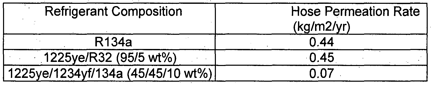
- Example 2 A layer of TPV is extruded over the assembly. Following that, a braid of PET filaments is applied, and outer protective layer of ETPV is extruded over the top. The mandrel is subsequently extracted to prepare the multi-layer hose.
- Example 2 A layer of TPV is extruded over the assembly. Following that, a braid of PET filaments is applied, and outer protective layer of ETPV is extruded over the top. The mandrel is subsequently extracted to prepare the multi-layer hose.
- results show hoses permeation for fluoroolefin compositions are at least equivalent to R134a. Since R32 is a small molecule, it contributes the most to hose permeation. The composition containing primarily fluoroolefins and a small amount of R134a had significantly lower permeation than R134a alone indicating, indicating fluoroolefins have overall lower permeation rates.
Abstract
Description


Claims
Priority Applications (6)
| Application Number | Priority Date | Filing Date | Title |
|---|---|---|---|
| CN200780041010A CN101827912A (en) | 2006-09-01 | 2007-08-31 | Method for circulating selected heat transfer fluids through a closed loop cycle |
| BRPI0714896-8A BRPI0714896A2 (en) | 2006-09-01 | 2007-08-31 | Method to provide you the shipping |
| US12/377,686 US20090314015A1 (en) | 2006-09-01 | 2007-08-31 | Method for circulating selected heat transfer fluids through a closed loop cycle |
| JP2009526746A JP2010513827A (en) | 2006-09-01 | 2007-08-31 | Method of circulating selected heat transfer fluid during closed loop cycle |
| CA002661007A CA2661007A1 (en) | 2006-09-01 | 2007-08-31 | Method for circulating selected heat transfer fluids through a closed loop cycle |
| EP07837628A EP2118229A2 (en) | 2006-09-01 | 2007-08-31 | Method for circulating selected heat transfer fluids through a closed loop cycle |
Applications Claiming Priority (2)
| Application Number | Priority Date | Filing Date | Title |
|---|---|---|---|
| US84171306P | 2006-09-01 | 2006-09-01 | |
| US60/841,713 | 2006-09-01 |
Publications (2)
| Publication Number | Publication Date |
|---|---|
| WO2008027555A2 true WO2008027555A2 (en) | 2008-03-06 |
| WO2008027555A3 WO2008027555A3 (en) | 2010-03-11 |
Family
ID=39136628
Family Applications (1)
| Application Number | Title | Priority Date | Filing Date |
|---|---|---|---|
| PCT/US2007/019205 WO2008027555A2 (en) | 2006-09-01 | 2007-08-31 | Method for circulating selected heat transfer fluids through a closed loop cycle |
Country Status (9)
| Country | Link |
|---|---|
| US (1) | US20090314015A1 (en) |
| EP (2) | EP2118229A2 (en) |
| JP (1) | JP2010513827A (en) |
| KR (1) | KR20090049617A (en) |
| CN (1) | CN101827912A (en) |
| BR (1) | BRPI0714896A2 (en) |
| CA (1) | CA2661007A1 (en) |
| RU (1) | RU2009111881A (en) |
| WO (1) | WO2008027555A2 (en) |
Cited By (57)
| Publication number | Priority date | Publication date | Assignee | Title |
|---|---|---|---|---|
| GB2457345A (en) * | 2007-10-12 | 2009-08-19 | Ineos Fluor Holdings Ltd | Heat transfer compositions |
| JP2009257745A (en) * | 2008-03-25 | 2009-11-05 | Daikin Ind Ltd | Refrigerating device |
| WO2010002014A1 (en) * | 2008-07-01 | 2010-01-07 | Daikin Industries, Ltd. | REFRIGERANT COMPOSITION COMPRISING DIFLUOROMETHANE (HFC32), PENTAFLUOROETHANE (HFC125) AND 2,3,3,3-TETRAFLUOROPROPENE (HFO1234yf) |
| WO2010002023A1 (en) * | 2008-07-01 | 2010-01-07 | Daikin Industries, Ltd. | REFRIGERANT COMPOSITION COMPRISING DIFLUOROMETHANE (HFC32), 2,3,3,3-TETRAFLUOROPROPENE (HFO1234yf) AND 1,1,1,2-TETRAFLUOROETHANE (HFC134a) |
| WO2010002022A1 (en) * | 2008-07-01 | 2010-01-07 | Daikin Industries, Ltd. | REFRIGERANT COMPOSITION COMPRISING PENTAFLUOROETHANE (HFC125), 2,3,3,3-TETRAFLUOROPROPENE (HFO1234yf) AND 1,1,1,2-TETRAFLUOROETHANE (HFC134a) |
| WO2010002020A1 (en) * | 2008-07-01 | 2010-01-07 | Daikin Industries, Ltd. | REFRIGERANT COMPOSITION COMPRISING 1,1,1,2-TETRAFLUOROETHANE (HFC134a) AND 2,3,3,3-TETRAFLUOROPROPENE (HFO1234yf) |
| WO2010002016A1 (en) * | 2008-07-01 | 2010-01-07 | Daikin Industries, Ltd. | REFRIGERANT COMPOSITION COMPRISING DIFLUOROMETHANE (HFC32) AND 2,3,3,3-TETRAFLUOROPROPENE (HFO1234yf) |
| FR2937906A1 (en) * | 2008-11-03 | 2010-05-07 | Arkema France | METHOD FOR HEATING AND / OR AIR CONDITIONING A VEHICLE |
| US20100186432A1 (en) * | 2007-07-27 | 2010-07-29 | E.I. Du Pont De Nemours And Company | Compositions comprising fluoroolefins |
| CN101851490A (en) * | 2010-06-04 | 2010-10-06 | 集美大学 | Refrigerant composition capable of replacing HFC-134a |
| CN101864276A (en) * | 2010-06-03 | 2010-10-20 | 集美大学 | Environment-friendly refrigerant |
| EP2309205A1 (en) | 2008-04-30 | 2011-04-13 | Sanden Corporation | Freezing circuit |
| US20110100605A1 (en) * | 2009-11-05 | 2011-05-05 | Wanlie Zheng | Cooling device and system |
| EP2320167A1 (en) * | 2008-08-04 | 2011-05-11 | Sanden Corporation | Resin material for refrigeration circuit |
| JP2011168771A (en) * | 2010-02-16 | 2011-09-01 | Ineos Fluor Holdings Ltd | Heat transfer composition |
| US8024937B2 (en) | 2007-06-21 | 2011-09-27 | E. I. Du Pont De Nemours And Company | Method for leak detection in heat transfer systems |
| CN102239228A (en) * | 2008-12-02 | 2011-11-09 | 墨西哥化学阿玛科股份有限公司 | Heat transfer compositions |
| GB2480517A (en) * | 2010-05-20 | 2011-11-23 | Mexichem Amanco Holding Sa | Heat transfer compositions |
| JP2012505279A (en) * | 2008-10-08 | 2012-03-01 | アルケマ フランス | Heat transfer fluid |
| JP2012509380A (en) * | 2008-11-20 | 2012-04-19 | アルケマ フランス | Composition comprising 2,3,3,3-tetrafluoropropene, vehicle heating and / or air conditioning method |
| KR20120045059A (en) * | 2009-08-28 | 2012-05-08 | 멕시켐 아만코 홀딩 에스.에이. 데 씨.브이. | Heat transfer compositions |
| CN102482557A (en) * | 2009-09-11 | 2012-05-30 | 阿克马法国公司 | Ternary compositions for high-capacity refrigeration |
| CN102482556A (en) * | 2009-09-11 | 2012-05-30 | 阿克马法国公司 | Ternary compositions for low-capacity refrigeration |
| EP2466179A1 (en) * | 2009-08-12 | 2012-06-20 | The Yokohama Rubber Company, Limited | Hose for transferring refrigerant |
| CN102753644A (en) * | 2010-02-16 | 2012-10-24 | 墨西哥化学阿玛科股份有限公司 | Heat transfer compositions |
| CN102753645A (en) * | 2010-02-16 | 2012-10-24 | 墨西哥化学阿玛科股份有限公司 | Heat transfer compositions |
| CN102762685A (en) * | 2010-02-16 | 2012-10-31 | 墨西哥化学阿玛科股份有限公司 | Heat transfer compositions |
| EP2149592A3 (en) * | 2008-07-30 | 2012-11-07 | Honeywell International Inc. | Compositions containing difluoromethane and fluorine substituted olefins |
| WO2012168607A1 (en) | 2011-06-07 | 2012-12-13 | Arkema France | Binary compositions of 1,3,3,3-tetrafluoropropene and ammonia |
| US8333901B2 (en) | 2007-10-12 | 2012-12-18 | Mexichem Amanco Holding S.A. De C.V. | Heat transfer compositions |
| CN102925110A (en) * | 2009-10-13 | 2013-02-13 | 天津大学 | Organic Rankine cycle mixed refrigerant containing HFC-143(1,1,2-halothane) |
| JP2013521368A (en) * | 2010-03-02 | 2013-06-10 | アルケマ フランス | Heat transfer fluid for centrifugal compressors |
| US8512591B2 (en) | 2007-10-12 | 2013-08-20 | Mexichem Amanco Holding S.A. De C.V. | Heat transfer compositions |
| US8628681B2 (en) | 2007-10-12 | 2014-01-14 | Mexichem Amanco Holding S.A. De C.V. | Heat transfer compositions |
| US8808570B2 (en) | 2010-05-20 | 2014-08-19 | Mexichem Amanco Holding S.A. De C.V. | Heat transfer compositions |
| US8911641B2 (en) | 2010-05-20 | 2014-12-16 | Mexichem Amanco Holding S.A. De C.V. | Heat transfer compositions |
| US9028706B2 (en) | 2011-02-10 | 2015-05-12 | Arkema France | Binary compositions of 2,3,3,3-tetrafluoropropene and of ammonia |
| US9039922B2 (en) | 2009-09-11 | 2015-05-26 | Arkema France | Low-temperature and average-temperature refrigeration |
| US9074115B2 (en) | 2009-08-28 | 2015-07-07 | Mexichem Amanco Holding S.A. De C.V. | Heat transfer compositions |
| JP2015129289A (en) * | 2008-11-19 | 2015-07-16 | イー・アイ・デュポン・ドウ・ヌムール・アンド・カンパニーE.I.Du Pont De Nemours And Company | Tetrafluoropropene compositions and uses thereof |
| JP2015163700A (en) * | 2008-07-30 | 2015-09-10 | ハネウェル・インターナショナル・インコーポレーテッド | Compositions containing difluoromethane and fluorine substituted olefins |
| US9133379B2 (en) | 2009-09-11 | 2015-09-15 | Arkema France | Binary refrigerating fluid |
| EP2516578B1 (en) | 2009-12-21 | 2016-06-22 | The Chemours Company FC, LLC | Compositions comprising tetrafluoropropene and difluoromethane and uses thereof |
| EP2652065B1 (en) | 2010-12-14 | 2016-07-27 | The Chemours Company FC, LLC | Use of refrigerants comprising e-1,3,3,3-tetrafluoropropene and at least one tetrafluoroethane for cooling |
| US9683157B2 (en) | 2009-09-11 | 2017-06-20 | Arkema France | Heat transfer method |
| US10023780B2 (en) | 2013-07-11 | 2018-07-17 | Arkema France | 2,3,3,3-tetrafluoropropene compositions having improved miscibility |
| US10035938B2 (en) | 2009-09-11 | 2018-07-31 | Arkema France | Heat transfer fluid replacing R-134a |
| EP2558544B1 (en) | 2010-04-16 | 2018-09-05 | The Chemours Company FC, LLC | Chillers containing a composition comprising 2,3,3,3-tetrafluoropropene and 1,1,1,2-tetrafluoroethane |
| US10266736B2 (en) | 2010-06-25 | 2019-04-23 | Mexichem Amanco Holding S.A. De C.V. | Heat transfer compositions |
| US10330364B2 (en) | 2014-06-26 | 2019-06-25 | Hudson Technologies, Inc. | System and method for retrofitting a refrigeration system from HCFC to HFC refrigerant |
| EP3202870B1 (en) | 2010-06-30 | 2019-10-02 | Arkema France | Use of a 2,3,3,3-tetrafluoropropene composition |
| CN111542582A (en) * | 2017-11-17 | 2020-08-14 | 霍尼韦尔国际公司 | Heat transfer compositions, methods, and systems |
| US10808157B2 (en) | 2008-11-03 | 2020-10-20 | Arkema France | Vehicle heating and/or air conditioning method |
| CN112111249A (en) * | 2020-09-28 | 2020-12-22 | 珠海格力电器股份有限公司 | Mixed refrigerant, heat exchange system and household appliance |
| EP3742084A4 (en) * | 2018-01-15 | 2021-01-13 | Mitsubishi Electric Corporation | Air-conditioning device |
| US11306235B2 (en) | 2009-07-29 | 2022-04-19 | Honeywell International Inc. | Compositions containing difluoromethane and fluorine substituted olefins |
| US11624534B2 (en) | 2007-05-11 | 2023-04-11 | The Chemours Company Fc, Llc | Method for exchanging heat in vapor compression heat transfer systems and vapor compression heat transfer systems comprising intermediate heat exchangers with dual-row evaporators or condensers |
Families Citing this family (47)
| Publication number | Priority date | Publication date | Assignee | Title |
|---|---|---|---|---|
| US20120097885A9 (en) * | 2003-10-27 | 2012-04-26 | Honeywell International Inc. | Compositions Containing Difluoromethane and Fluorine Substituted Olefins |
| US7510939B2 (en) * | 2006-01-31 | 2009-03-31 | International Business Machines Corporation | Microelectronic structure by selective deposition |
| FR2942237B1 (en) * | 2009-02-13 | 2013-01-04 | Arkema France | METHOD FOR HEATING AND / OR AIR CONDITIONING A VEHICLE |
| KR101446386B1 (en) * | 2009-02-26 | 2014-10-01 | 다이킨 고교 가부시키가이샤 | Refrigerant composition containing hydrofluoropropene with low-global warming potential |
| US8980118B2 (en) | 2009-05-08 | 2015-03-17 | Honeywell International Inc. | Heat transfer compositions and methods |
| US9845419B2 (en) * | 2009-07-29 | 2017-12-19 | Honeywell International Inc. | Low GWP heat transfer compositions containing difluoromethane and 1,3,3,3-tetrafluoropropene |
| CN102732220A (en) * | 2009-10-13 | 2012-10-17 | 天津大学 | Organic Rankine cycle mixed refrigerant containing HFO-1234yf(CF3CF=CH2) |
| CN102311719A (en) * | 2009-10-13 | 2012-01-11 | 天津大学 | Organic Rankine cycle mixed working fluid containing HFO-1234yf(CF3CF=CH2) |
| FR2954342B1 (en) * | 2009-12-18 | 2012-03-16 | Arkema France | HEAT TRANSFER FLUIDS WITH REDUCED FLAMMABILITY |
| GB201002617D0 (en) * | 2010-02-16 | 2010-03-31 | Ineos Fluor Holdings Ltd | Heat transfer compositions |
| FR2959999B1 (en) | 2010-05-11 | 2012-07-20 | Arkema France | HEAT TRANSFER FLUIDS AND THEIR USE IN COUNTER-CURRENT HEAT EXCHANGERS |
| FR2959997B1 (en) | 2010-05-11 | 2012-06-08 | Arkema France | HEAT TRANSFER FLUIDS AND THEIR USE IN COUNTER-CURRENT HEAT EXCHANGERS |
| FR2964977B1 (en) | 2010-09-20 | 2013-11-01 | Arkema France | COMPOSITION BASED ON 3,3,3-TETRAFLUOROPROPENE |
| FR2973805B1 (en) * | 2011-04-08 | 2013-04-12 | Arkema France | COMPOSITIONS COMPRISING 3,3,3-TRIFLUOROPROPENE AND AMMONIA |
| JP2014141537A (en) * | 2011-05-19 | 2014-08-07 | Asahi Glass Co Ltd | Working medium and heat cycle system |
| JP2014141538A (en) * | 2011-05-19 | 2014-08-07 | Asahi Glass Co Ltd | Working medium and heat cycle system |
| KR20130017040A (en) * | 2011-08-09 | 2013-02-19 | 현대자동차주식회사 | Multilayer tube for transmission oil cooler |
| US9039923B2 (en) | 2012-02-14 | 2015-05-26 | United Technologies Corporation | Composition of zeotropic mixtures having predefined temperature glide |
| CN102676119B (en) * | 2012-05-24 | 2014-01-29 | 浙江大学 | Refrigerant with low GWP (global warming potential) and preparation method thereof |
| US9783721B2 (en) | 2012-08-20 | 2017-10-10 | Honeywell International Inc. | Low GWP heat transfer compositions |
| DE102012108468A1 (en) * | 2012-09-11 | 2014-03-13 | Amovis Gmbh | Working mixture for steam power plants |
| US8940180B2 (en) * | 2012-11-21 | 2015-01-27 | Honeywell International Inc. | Low GWP heat transfer compositions |
| CN104955916A (en) * | 2012-12-04 | 2015-09-30 | 霍尼韦尔国际公司 | Low GWP heat transfer compositions |
| US11885561B2 (en) * | 2012-12-04 | 2024-01-30 | Conocophillips Company | Low global-warming refrigerants in LNG processing |
| US9982180B2 (en) | 2013-02-13 | 2018-05-29 | Honeywell International Inc. | Heat transfer compositions and methods |
| CA3015523A1 (en) * | 2016-02-29 | 2017-09-08 | The Chemours Company Fc, Llc | Refrigerant mixtures comprising difluoromethane, pentafluoroethane, tetrafluoroethane, tetrafluoropropene, and carbon dioxide and uses thereof |
| RU2661418C1 (en) * | 2017-01-24 | 2018-07-16 | Сергей Вячеславович Поспелов | Turbocharger thermal machine operating on a closed thermodynamic cycle with internal heat recovery |
| FR3064264B1 (en) | 2017-03-21 | 2019-04-05 | Arkema France | COMPOSITION BASED ON TETRAFLUOROPROPENE |
| FR3064275B1 (en) * | 2017-03-21 | 2019-06-07 | Arkema France | METHOD FOR HEATING AND / OR AIR CONDITIONING A VEHICLE |
| WO2019109000A1 (en) * | 2017-11-30 | 2019-06-06 | Honeywell International Inc. | Heat transfer compositions, methods, and systems |
| US20190161662A1 (en) * | 2017-11-30 | 2019-05-30 | Honeywell International Inc. | Heat transfer compositions, methods, and systems |
| US11078392B2 (en) | 2017-12-29 | 2021-08-03 | Trane International Inc. | Lower GWP refrigerant compositions |
| CN110343510B (en) * | 2018-04-02 | 2021-06-04 | 江西天宇化工有限公司 | Non-flammable mixed refrigerant with low-temperature chamber effect and application thereof |
| WO2019220460A1 (en) * | 2018-05-15 | 2019-11-21 | Srf Limited | Azeotrope or azeotrope like compositions comprising 1234yf |
| CN112352029A (en) * | 2018-06-28 | 2021-02-09 | 科慕埃弗西有限公司 | Refrigerant blends having low global warming potential |
| CN109971433B (en) * | 2019-04-08 | 2021-04-13 | 中国科学院理化技术研究所 | Multi-component mixed refrigerant |
| CN110628390B (en) * | 2019-09-12 | 2020-12-15 | 珠海格力电器股份有限公司 | Environment-friendly mixed refrigerant, composition and heat exchange system |
| CN110746936B (en) * | 2019-10-11 | 2021-05-04 | 金华永和氟化工有限公司 | Environment-friendly mixed refrigerant |
| CN110878194B (en) * | 2019-10-16 | 2020-11-17 | 珠海格力电器股份有限公司 | R13I 1-containing environment-friendly mixed refrigerant and heat exchange system |
| CN110845997B (en) * | 2019-10-16 | 2020-12-22 | 珠海格力电器股份有限公司 | Heat transfer medium and composition suitable for cooler |
| CN111592858B (en) * | 2020-05-21 | 2022-01-11 | 冰山松洋生物科技(大连)有限公司 | Mixed refrigerant, refrigeration system and refrigeration device |
| US11028300B1 (en) | 2020-09-16 | 2021-06-08 | David L. Couchot | Environmentally friendly refrigerant compositions |
| CN113046029B (en) * | 2021-02-09 | 2022-06-28 | 浙江衢化氟化学有限公司 | Composition containing fluoroolefin and preparation method thereof |
| CN113388371B (en) * | 2021-06-07 | 2022-06-24 | 湖北瑞能华辉能源管理有限公司 | Quaternary mixed refrigerant capable of replacing R22 or R410a and application thereof |
| CN113980649B (en) * | 2021-11-09 | 2022-07-15 | 珠海格力电器股份有限公司 | Mixed refrigerant and air conditioning system |
| CN114716975B (en) * | 2022-04-08 | 2023-04-14 | 大连理工大学 | Heat transfer working medium suitable for reverse Carnot circulation system |
| JP2024002978A (en) * | 2022-06-23 | 2024-01-11 | ダイキン工業株式会社 | Transport method, refrigeration method, refrigeration system, and hose for refrigeration system |
Citations (10)
| Publication number | Priority date | Publication date | Assignee | Title |
|---|---|---|---|---|
| US4510974A (en) | 1980-08-21 | 1985-04-16 | Hitachi Cable Ltd. | Fluid conveying hose |
| EP1010929A1 (en) | 1998-12-16 | 2000-06-21 | Tokai Rubber Industries, Ltd. | Hose for a refrigerant for an electrically driven compressor |
| US6261473B1 (en) | 1998-06-26 | 2001-07-17 | Kabushiki Kaisha Sanai | Working fluid containing 1,1-difluoroethane, 1,1,2,2-tetrafluoroethane and carbon dioxide |
| US20010013374A1 (en) | 2000-02-16 | 2001-08-16 | Nobuaki Niki | Fluid-impermeable composite hose |
| US20020056284A1 (en) | 2000-11-13 | 2002-05-16 | Tetsuji Nobuta | Refrigeration system |
| US20020056481A1 (en) | 2000-09-26 | 2002-05-16 | The Yokohama Rubber Co., Ltd. | Low permeable hose and method for producing the same |
| US20040040609A1 (en) | 2002-08-30 | 2004-03-04 | The Yokohama Rubber Co., Ltd. | Ultra-low permeation hose and method of manufacture |
| US20050233923A1 (en) | 2004-04-16 | 2005-10-20 | Honeywell International, Inc. | Azeotrope-like trifluoroiodomethane compositions |
| WO2005103188A1 (en) | 2004-04-16 | 2005-11-03 | Honeywell International Inc. | Azeotrope-like compositions of tetrafluoropropene and pentafluoropropene |
| US7055553B2 (en) | 2003-02-27 | 2006-06-06 | Titeflex Corporation | Laminated hose construction having one or more intermediate metal barrier layers |
Family Cites Families (30)
| Publication number | Priority date | Publication date | Assignee | Title |
|---|---|---|---|---|
| US3159183A (en) * | 1961-07-17 | 1964-12-01 | Moore & Co Samuel | Composite tubing product, and apparatus and method for manufacturing same |
| USRE36951E (en) * | 1994-08-29 | 2000-11-14 | Spectronics Corporation | Method of introducing leak detection dye into an air conditioning or refrigeration system including solid or semi-solid fluorescent dyes |
| DE19837497A1 (en) * | 1998-08-13 | 2000-02-24 | Trinova Aeroquip Gmbh | Flexible pipe for liquid carbon dioxide has metal or synthetic coated inner layer facilitating transport of natural cooling fluid and reducing danger of leakage |
| EP1062451B1 (en) * | 1998-08-13 | 2002-06-05 | Aeroquip Zweigniederlassung der Aeroquip-Vickers International GmbH | Hollow body in the form of a flexible bar |
| US5957164A (en) * | 1998-09-10 | 1999-09-28 | Aeroquip Corporation | Refrigerant hose |
| JP2000205458A (en) * | 1999-01-11 | 2000-07-25 | Tokai Rubber Ind Ltd | Hose for carbon dioxide refrigerant transport |
| JP4496629B2 (en) * | 1999-09-27 | 2010-07-07 | 横浜ゴム株式会社 | Low permeability hose and method for manufacturing the same |
| US6204405B1 (en) | 1999-12-22 | 2001-03-20 | Sigma-Aldrich Co. | Economical and convenient procedures for the synthesis of catecholborane |
| US20010006712A1 (en) * | 1999-12-27 | 2001-07-05 | Motoshige Hibino | Hose of impermeability and a process for manufacturing the same |
| US20010045237A1 (en) * | 2000-02-03 | 2001-11-29 | Hisanobu Monobe | Refrigerant transporting rubber hose |
| JP2001263543A (en) * | 2000-03-21 | 2001-09-26 | Tokai Rubber Ind Ltd | Impermeable composite hose |
| JP2001263544A (en) * | 2000-03-21 | 2001-09-26 | Tokai Rubber Ind Ltd | Impermeable composite hose |
| US20040089839A1 (en) * | 2002-10-25 | 2004-05-13 | Honeywell International, Inc. | Fluorinated alkene refrigerant compositions |
| EP2277942A3 (en) * | 2002-10-25 | 2014-07-09 | Honeywell International, Incorporated. | Compositions containing fluorine substituted olefins |
| US7279451B2 (en) * | 2002-10-25 | 2007-10-09 | Honeywell International Inc. | Compositions containing fluorine substituted olefins |
| BRPI0402583A (en) * | 2003-07-11 | 2005-05-31 | Goodyear Tire & Rubber | Refrigerant hose |
| US20050211326A1 (en) * | 2004-03-29 | 2005-09-29 | Motoshige Hibino | Composite hose with a corrugated metal tube and method for making the same |
| JP4732720B2 (en) * | 2004-07-15 | 2011-07-27 | 東海ゴム工業株式会社 | Refrigerant transport hose |
| US20060030719A1 (en) * | 2004-08-03 | 2006-02-09 | Fagan Paul J | Cis-3,5-disubstituted-dihydro-furan-2-ones and the preparation and use thereof |
| US20060243945A1 (en) * | 2005-03-04 | 2006-11-02 | Minor Barbara H | Compositions comprising a fluoroolefin |
| US7569170B2 (en) * | 2005-03-04 | 2009-08-04 | E.I. Du Pont De Nemours And Company | Compositions comprising a fluoroolefin |
| US20060243944A1 (en) * | 2005-03-04 | 2006-11-02 | Minor Barbara H | Compositions comprising a fluoroolefin |
| US7708903B2 (en) * | 2005-11-01 | 2010-05-04 | E.I. Du Pont De Nemours And Company | Compositions comprising fluoroolefins and uses thereof |
| US20080017266A1 (en) * | 2006-07-24 | 2008-01-24 | Doshi Shailesh R | High pressure barrier hose and method of manufacture |
| US20080053553A1 (en) * | 2006-09-01 | 2008-03-06 | Doshi Shailesh R | Method for circulating select heat transfer fluids through closed loop cycles, incorporating high pressure barrier hoses |
| EP2064533A2 (en) * | 2006-09-15 | 2009-06-03 | E.I. Du Pont De Nemours And Company | Method of detecting leaks of fluoroolefin compositions and sensors used therefor |
| WO2008033568A2 (en) * | 2006-09-15 | 2008-03-20 | E.I. Du Pont De Nemours And Company | Determination of the components of a fluoroolefin composition |
| WO2008085314A2 (en) * | 2006-12-19 | 2008-07-17 | E. I. Du Pont De Nemours And Company | Dual row heat exchanger and automobile bumper incorporating the same |
| JP2010530952A (en) * | 2007-06-21 | 2010-09-16 | イー・アイ・デュポン・ドウ・ヌムール・アンド・カンパニー | Leakage detection method in heat transfer system |
| BRPI0819492A2 (en) * | 2007-12-20 | 2015-05-26 | Du Pont | "cooling system and method for diverting a reservoir into a cooling system" |
-
2007
- 2007-08-31 EP EP07837628A patent/EP2118229A2/en not_active Withdrawn
- 2007-08-31 WO PCT/US2007/019205 patent/WO2008027555A2/en active Application Filing
- 2007-08-31 RU RU2009111881/06A patent/RU2009111881A/en unknown
- 2007-08-31 US US12/377,686 patent/US20090314015A1/en not_active Abandoned
- 2007-08-31 KR KR1020097006602A patent/KR20090049617A/en not_active Application Discontinuation
- 2007-08-31 BR BRPI0714896-8A patent/BRPI0714896A2/en not_active IP Right Cessation
- 2007-08-31 CN CN200780041010A patent/CN101827912A/en active Pending
- 2007-08-31 CA CA002661007A patent/CA2661007A1/en not_active Abandoned
- 2007-08-31 EP EP13157634.0A patent/EP2602299A2/en not_active Withdrawn
- 2007-08-31 JP JP2009526746A patent/JP2010513827A/en not_active Ceased
Patent Citations (10)
| Publication number | Priority date | Publication date | Assignee | Title |
|---|---|---|---|---|
| US4510974A (en) | 1980-08-21 | 1985-04-16 | Hitachi Cable Ltd. | Fluid conveying hose |
| US6261473B1 (en) | 1998-06-26 | 2001-07-17 | Kabushiki Kaisha Sanai | Working fluid containing 1,1-difluoroethane, 1,1,2,2-tetrafluoroethane and carbon dioxide |
| EP1010929A1 (en) | 1998-12-16 | 2000-06-21 | Tokai Rubber Industries, Ltd. | Hose for a refrigerant for an electrically driven compressor |
| US20010013374A1 (en) | 2000-02-16 | 2001-08-16 | Nobuaki Niki | Fluid-impermeable composite hose |
| US20020056481A1 (en) | 2000-09-26 | 2002-05-16 | The Yokohama Rubber Co., Ltd. | Low permeable hose and method for producing the same |
| US20020056284A1 (en) | 2000-11-13 | 2002-05-16 | Tetsuji Nobuta | Refrigeration system |
| US20040040609A1 (en) | 2002-08-30 | 2004-03-04 | The Yokohama Rubber Co., Ltd. | Ultra-low permeation hose and method of manufacture |
| US7055553B2 (en) | 2003-02-27 | 2006-06-06 | Titeflex Corporation | Laminated hose construction having one or more intermediate metal barrier layers |
| US20050233923A1 (en) | 2004-04-16 | 2005-10-20 | Honeywell International, Inc. | Azeotrope-like trifluoroiodomethane compositions |
| WO2005103188A1 (en) | 2004-04-16 | 2005-11-03 | Honeywell International Inc. | Azeotrope-like compositions of tetrafluoropropene and pentafluoropropene |
Cited By (118)
| Publication number | Priority date | Publication date | Assignee | Title |
|---|---|---|---|---|
| US11624534B2 (en) | 2007-05-11 | 2023-04-11 | The Chemours Company Fc, Llc | Method for exchanging heat in vapor compression heat transfer systems and vapor compression heat transfer systems comprising intermediate heat exchangers with dual-row evaporators or condensers |
| US8024937B2 (en) | 2007-06-21 | 2011-09-27 | E. I. Du Pont De Nemours And Company | Method for leak detection in heat transfer systems |
| US20100186432A1 (en) * | 2007-07-27 | 2010-07-29 | E.I. Du Pont De Nemours And Company | Compositions comprising fluoroolefins |
| US8628681B2 (en) | 2007-10-12 | 2014-01-14 | Mexichem Amanco Holding S.A. De C.V. | Heat transfer compositions |
| US8333901B2 (en) | 2007-10-12 | 2012-12-18 | Mexichem Amanco Holding S.A. De C.V. | Heat transfer compositions |
| US8512591B2 (en) | 2007-10-12 | 2013-08-20 | Mexichem Amanco Holding S.A. De C.V. | Heat transfer compositions |
| GB2457345B (en) * | 2007-10-12 | 2012-02-08 | Ineos Fluor Holdings Ltd | Heat transfer compositions |
| GB2457345A (en) * | 2007-10-12 | 2009-08-19 | Ineos Fluor Holdings Ltd | Heat transfer compositions |
| US8999190B2 (en) | 2007-10-12 | 2015-04-07 | Mexichem Amanco Holding S.A. De C.V. | Heat transfer compositions |
| US7914696B2 (en) | 2007-10-12 | 2011-03-29 | Ineos Fluor Holdings Limited | Heat transfer compositions |
| JP2009257743A (en) * | 2008-03-25 | 2009-11-05 | Daikin Ind Ltd | Refrigerating device |
| JP2009257741A (en) * | 2008-03-25 | 2009-11-05 | Daikin Ind Ltd | Refrigerating device |
| JP2009257744A (en) * | 2008-03-25 | 2009-11-05 | Daikin Ind Ltd | Refrigerating device |
| JP2009257745A (en) * | 2008-03-25 | 2009-11-05 | Daikin Ind Ltd | Refrigerating device |
| EP2309205A1 (en) | 2008-04-30 | 2011-04-13 | Sanden Corporation | Freezing circuit |
| EP2309205A4 (en) * | 2008-04-30 | 2011-06-29 | Sanden Corp | Freezing circuit |
| JP2014129543A (en) * | 2008-07-01 | 2014-07-10 | Daikin Ind Ltd | REFRIGERANT COMPOSITION CONTAINING DIFLUOROMETHANE (HFC32), PENTAFLUOROETHANE (HFC125) AND 2,3,3,3-TETRAFLUOROPROPENE (HFO1234yf) |
| CN102083934B (en) * | 2008-07-01 | 2013-06-12 | 大金工业株式会社 | Refrigerant composition comprising difluoromethane (HFC32), pentafluoroethane (HFC125) and 2,3,3,3-tetrafluoropropene (HFO1234yf) |
| EP2460865A1 (en) * | 2008-07-01 | 2012-06-06 | Daikin Industries, Ltd. | Refrigerant composition comprising difluoromethane (HFC32), pentafluoroethane (HFC125), and 2,3,3,3,-tetrafluoropropene (HFO1234yf) |
| CN102083935A (en) * | 2008-07-01 | 2011-06-01 | 大金工业株式会社 | Refrigerant composition comprising 1,1,1,2-tetrafluoroethane (HFC134a) and 2,3,3,3-tetrafluoropropene (HFO1234yf) |
| CN102083934A (en) * | 2008-07-01 | 2011-06-01 | 大金工业株式会社 | Refrigerant composition comprising difluoromethane (HFC32), pentafluoroethane (HFC125) and 2,3,3,3-tetrafluoropropene (HFO1234yf) |
| US8318039B2 (en) | 2008-07-01 | 2012-11-27 | Daikin Industries, Ltd. | Refrigerant composition comprising 1,1,1,2-tetrafluoroethane (HFC134a) and 2,3,3,3-tetrafluoropropene (HFO1234yf) |
| WO2010002014A1 (en) * | 2008-07-01 | 2010-01-07 | Daikin Industries, Ltd. | REFRIGERANT COMPOSITION COMPRISING DIFLUOROMETHANE (HFC32), PENTAFLUOROETHANE (HFC125) AND 2,3,3,3-TETRAFLUOROPROPENE (HFO1234yf) |
| US8496845B2 (en) | 2008-07-01 | 2013-07-30 | Daikin Industries, Ltd. | Refrigerant composition comprising difluoromethane (HFC32), pentafluoroethane (HFC125) and 2, 3, 3, 3-tetrafluoropropene (HFO1234yf) |
| JP2011525204A (en) * | 2008-07-01 | 2011-09-15 | ダイキン工業株式会社 | Refrigerant composition comprising difluoromethane (HFC32), pentafluoroethane (HFC125) and 2,3,3,3-tetrafluoropropene (HFO1234yf) |
| WO2010002023A1 (en) * | 2008-07-01 | 2010-01-07 | Daikin Industries, Ltd. | REFRIGERANT COMPOSITION COMPRISING DIFLUOROMETHANE (HFC32), 2,3,3,3-TETRAFLUOROPROPENE (HFO1234yf) AND 1,1,1,2-TETRAFLUOROETHANE (HFC134a) |
| WO2010002016A1 (en) * | 2008-07-01 | 2010-01-07 | Daikin Industries, Ltd. | REFRIGERANT COMPOSITION COMPRISING DIFLUOROMETHANE (HFC32) AND 2,3,3,3-TETRAFLUOROPROPENE (HFO1234yf) |
| EP2465909A1 (en) * | 2008-07-01 | 2012-06-20 | Daikin Industries, Ltd. | Refrigerant composition comprising 1,1,1,2-tetrafluoroethane (HFC134a) and 2,3,3,3-tetrafluropropene (HFO1234yf) |
| WO2010002020A1 (en) * | 2008-07-01 | 2010-01-07 | Daikin Industries, Ltd. | REFRIGERANT COMPOSITION COMPRISING 1,1,1,2-TETRAFLUOROETHANE (HFC134a) AND 2,3,3,3-TETRAFLUOROPROPENE (HFO1234yf) |
| WO2010002022A1 (en) * | 2008-07-01 | 2010-01-07 | Daikin Industries, Ltd. | REFRIGERANT COMPOSITION COMPRISING PENTAFLUOROETHANE (HFC125), 2,3,3,3-TETRAFLUOROPROPENE (HFO1234yf) AND 1,1,1,2-TETRAFLUOROETHANE (HFC134a) |
| EP3498802A1 (en) * | 2008-07-30 | 2019-06-19 | Honeywell International Inc. | Compositions containing difluoromethane and fluorine substituted olefins |
| CN107384323A (en) * | 2008-07-30 | 2017-11-24 | 霍尼韦尔国际公司 | The composition of the alkene substituted containing difluoromethane and fluorine |
| JP2015163700A (en) * | 2008-07-30 | 2015-09-10 | ハネウェル・インターナショナル・インコーポレーテッド | Compositions containing difluoromethane and fluorine substituted olefins |
| EP3093323A1 (en) * | 2008-07-30 | 2016-11-16 | Honeywell International Inc. | Compositions containing difluoromethane and fluorine substituted |
| EP2149592A3 (en) * | 2008-07-30 | 2012-11-07 | Honeywell International Inc. | Compositions containing difluoromethane and fluorine substituted olefins |
| EP2320167A4 (en) * | 2008-08-04 | 2011-07-20 | Sanden Corp | Resin material for refrigeration circuit |
| EP2320167A1 (en) * | 2008-08-04 | 2011-05-11 | Sanden Corporation | Resin material for refrigeration circuit |
| JP2014141681A (en) * | 2008-10-08 | 2014-08-07 | Arkema France | Heat transfer fluid |
| JP2021066889A (en) * | 2008-10-08 | 2021-04-30 | アルケマ フランス | Heat transfer fluid |
| EP2331651B1 (en) | 2008-10-08 | 2018-02-21 | Arkema France | Heat transfer fluid |
| JP2012505279A (en) * | 2008-10-08 | 2012-03-01 | アルケマ フランス | Heat transfer fluid |
| JP2019052317A (en) * | 2008-10-08 | 2019-04-04 | アルケマ フランス | Heat transfer fluid |
| US11130893B2 (en) | 2008-10-08 | 2021-09-28 | Arkema France | Heat transfer fluid |
| US9599381B2 (en) | 2008-10-08 | 2017-03-21 | Arkema France | Heat transfer fluid |
| JP2016176082A (en) * | 2008-10-08 | 2016-10-06 | アルケマ フランス | Heat transfer fluid |
| EP2342302B1 (en) | 2008-11-03 | 2017-04-26 | Arkema France | Vehicle heating and/or air conditioning method |
| US10808157B2 (en) | 2008-11-03 | 2020-10-20 | Arkema France | Vehicle heating and/or air conditioning method |
| WO2010061084A1 (en) | 2008-11-03 | 2010-06-03 | Arkema France | Vehicle heating and/or air conditioning method |
| FR2937906A1 (en) * | 2008-11-03 | 2010-05-07 | Arkema France | METHOD FOR HEATING AND / OR AIR CONDITIONING A VEHICLE |
| EP3205699A1 (en) * | 2008-11-03 | 2017-08-16 | Arkema France | Heating and/or air conditioning method for a vehicle |
| JP2015129289A (en) * | 2008-11-19 | 2015-07-16 | イー・アイ・デュポン・ドウ・ヌムール・アンド・カンパニーE.I.Du Pont De Nemours And Company | Tetrafluoropropene compositions and uses thereof |
| JP2012509380A (en) * | 2008-11-20 | 2012-04-19 | アルケマ フランス | Composition comprising 2,3,3,3-tetrafluoropropene, vehicle heating and / or air conditioning method |
| JP2012510552A (en) * | 2008-12-02 | 2012-05-10 | メキシケム、アマンコ、ホールディング、ソシエダッド、アノニマ、デ、カピタル、バリアブレ | Heat transfer composition |
| CN102272259A (en) * | 2008-12-02 | 2011-12-07 | 墨西哥化学阿玛科股份有限公司 | Heat transfer compositions |
| CN102239228A (en) * | 2008-12-02 | 2011-11-09 | 墨西哥化学阿玛科股份有限公司 | Heat transfer compositions |
| US11306235B2 (en) | 2009-07-29 | 2022-04-19 | Honeywell International Inc. | Compositions containing difluoromethane and fluorine substituted olefins |
| US8580366B2 (en) | 2009-08-12 | 2013-11-12 | The Yokohama Rubber Co., Ltd. | Hose for refrigerant transport use |
| EP2466179A1 (en) * | 2009-08-12 | 2012-06-20 | The Yokohama Rubber Company, Limited | Hose for transferring refrigerant |
| EP2466179A4 (en) * | 2009-08-12 | 2013-03-06 | Yokohama Rubber Co Ltd | Hose for transferring refrigerant |
| KR20120045059A (en) * | 2009-08-28 | 2012-05-08 | 멕시켐 아만코 홀딩 에스.에이. 데 씨.브이. | Heat transfer compositions |
| KR101656320B1 (en) * | 2009-08-28 | 2016-09-09 | 멕시켐 아만코 홀딩 에스.에이. 데 씨.브이. | Heat transfer compositions |
| US8894874B2 (en) | 2009-08-28 | 2014-11-25 | Mexichem Amanco Holding S.A. De C.V. | Heat transfer compositions |
| JP2013503230A (en) * | 2009-08-28 | 2013-01-31 | メキシケム、アマンコ、ホールディング、ソシエダッド、アノニマ、デ、カピタル、バリアブレ | Heat transfer composition |
| US9074115B2 (en) | 2009-08-28 | 2015-07-07 | Mexichem Amanco Holding S.A. De C.V. | Heat transfer compositions |
| CN104726067A (en) * | 2009-08-28 | 2015-06-24 | 墨西哥化学阿玛科股份有限公司 | Heat Transfer Compositions |
| JP2015061922A (en) * | 2009-08-28 | 2015-04-02 | メキシケム、アマンコ、ホールディング、ソシエダッド、アノニマ、デ、カピタル、バリアブレMexichem Amanco Holding S.A. De C.V. | Heat transfer composition |
| US10358592B2 (en) | 2009-09-11 | 2019-07-23 | Arkema France | Heat transfer method |
| CN102482556A (en) * | 2009-09-11 | 2012-05-30 | 阿克马法国公司 | Ternary compositions for low-capacity refrigeration |
| US9039922B2 (en) | 2009-09-11 | 2015-05-26 | Arkema France | Low-temperature and average-temperature refrigeration |
| US10035938B2 (en) | 2009-09-11 | 2018-07-31 | Arkema France | Heat transfer fluid replacing R-134a |
| US9884984B2 (en) | 2009-09-11 | 2018-02-06 | Arkema France | Binary refrigerating fluid |
| US10858562B2 (en) | 2009-09-11 | 2020-12-08 | Arkema France | Binary refrigerating fluid |
| CN102482556B (en) * | 2009-09-11 | 2015-07-29 | 阿克马法国公司 | For the ternary composition of low-capacity refrigeration |
| CN102482557B (en) * | 2009-09-11 | 2015-09-02 | 阿克马法国公司 | For the ternary composition of high-capacity refrigeration |
| US9683157B2 (en) | 2009-09-11 | 2017-06-20 | Arkema France | Heat transfer method |
| US9133379B2 (en) | 2009-09-11 | 2015-09-15 | Arkema France | Binary refrigerating fluid |
| CN104974719A (en) * | 2009-09-11 | 2015-10-14 | 阿克马法国公司 | Ternary Compositions For High-capacity Refrigeration |
| US10125296B2 (en) | 2009-09-11 | 2018-11-13 | Arkema France | Binary refrigerating fluid |
| US10316231B2 (en) | 2009-09-11 | 2019-06-11 | Arkema France | Low-temperature and average-temperature refrigeration |
| CN102482557A (en) * | 2009-09-11 | 2012-05-30 | 阿克马法国公司 | Ternary compositions for high-capacity refrigeration |
| CN102925110A (en) * | 2009-10-13 | 2013-02-13 | 天津大学 | Organic Rankine cycle mixed refrigerant containing HFC-143(1,1,2-halothane) |
| US20110100605A1 (en) * | 2009-11-05 | 2011-05-05 | Wanlie Zheng | Cooling device and system |
| EP2516578B1 (en) | 2009-12-21 | 2016-06-22 | The Chemours Company FC, LLC | Compositions comprising tetrafluoropropene and difluoromethane and uses thereof |
| US9175202B2 (en) | 2010-02-16 | 2015-11-03 | Mexichem Amanco Holding S.A. De C.V. | Heat transfer compositions |
| JP2011168771A (en) * | 2010-02-16 | 2011-09-01 | Ineos Fluor Holdings Ltd | Heat transfer composition |
| CN102762685A (en) * | 2010-02-16 | 2012-10-31 | 墨西哥化学阿玛科股份有限公司 | Heat transfer compositions |
| CN102753645A (en) * | 2010-02-16 | 2012-10-24 | 墨西哥化学阿玛科股份有限公司 | Heat transfer compositions |
| US8926856B2 (en) | 2010-02-16 | 2015-01-06 | Mexichem Amanco Holding S.A. De C.V. | Heat transfer compositions |
| CN102753644A (en) * | 2010-02-16 | 2012-10-24 | 墨西哥化学阿玛科股份有限公司 | Heat transfer compositions |
| JP2013521368A (en) * | 2010-03-02 | 2013-06-10 | アルケマ フランス | Heat transfer fluid for centrifugal compressors |
| CN105860934A (en) * | 2010-03-02 | 2016-08-17 | 阿克马法国公司 | Heat-transfer fluid for centrifugal compressor |
| EP2558544B1 (en) | 2010-04-16 | 2018-09-05 | The Chemours Company FC, LLC | Chillers containing a composition comprising 2,3,3,3-tetrafluoropropene and 1,1,1,2-tetrafluoroethane |
| GB2480517A (en) * | 2010-05-20 | 2011-11-23 | Mexichem Amanco Holding Sa | Heat transfer compositions |
| US8808570B2 (en) | 2010-05-20 | 2014-08-19 | Mexichem Amanco Holding S.A. De C.V. | Heat transfer compositions |
| GB2480517B (en) * | 2010-05-20 | 2013-03-06 | Mexichem Amanco Holding Sa | Heat transfer compositions |
| US8808571B2 (en) | 2010-05-20 | 2014-08-19 | Mexichem Amanco Holding S.A. De C.V. | Heat transfer compositions |
| US8911641B2 (en) | 2010-05-20 | 2014-12-16 | Mexichem Amanco Holding S.A. De C.V. | Heat transfer compositions |
| US9309450B2 (en) | 2010-05-20 | 2016-04-12 | Mexichem Amanco Holding S.A. De C.V. | Heat transfer compositions |
| CN101864276A (en) * | 2010-06-03 | 2010-10-20 | 集美大学 | Environment-friendly refrigerant |
| CN101851490A (en) * | 2010-06-04 | 2010-10-06 | 集美大学 | Refrigerant composition capable of replacing HFC-134a |
| CN101851490B (en) * | 2010-06-04 | 2012-10-24 | 集美大学 | Refrigerant composition capable of replacing HFC-134a |
| US11760911B2 (en) | 2010-06-25 | 2023-09-19 | Mexichem Amanco Holding S.A. De C.V. | Heat transfer compositions |
| US10844260B2 (en) | 2010-06-25 | 2020-11-24 | Mexichem Amanco Holding S.A. De C.V. | Heat transfer compositions |
| US10266736B2 (en) | 2010-06-25 | 2019-04-23 | Mexichem Amanco Holding S.A. De C.V. | Heat transfer compositions |
| EP3202870B1 (en) | 2010-06-30 | 2019-10-02 | Arkema France | Use of a 2,3,3,3-tetrafluoropropene composition |
| EP2652065B2 (en) † | 2010-12-14 | 2019-05-15 | The Chemours Company FC, LLC | Use of refrigerants comprising e-1,3,3,3-tetrafluoropropene and at least one tetrafluoroethane for cooling |
| EP2652065B1 (en) | 2010-12-14 | 2016-07-27 | The Chemours Company FC, LLC | Use of refrigerants comprising e-1,3,3,3-tetrafluoropropene and at least one tetrafluoroethane for cooling |
| US9028706B2 (en) | 2011-02-10 | 2015-05-12 | Arkema France | Binary compositions of 2,3,3,3-tetrafluoropropene and of ammonia |
| US8951432B2 (en) | 2011-06-07 | 2015-02-10 | Arkema France | Binary compositions of 1,3,3,3-tetrafluoropropene and ammonia |
| WO2012168607A1 (en) | 2011-06-07 | 2012-12-13 | Arkema France | Binary compositions of 1,3,3,3-tetrafluoropropene and ammonia |
| US10023780B2 (en) | 2013-07-11 | 2018-07-17 | Arkema France | 2,3,3,3-tetrafluoropropene compositions having improved miscibility |
| US10377935B2 (en) | 2013-07-11 | 2019-08-13 | Arkema France | 2,3,3,3-tetrafluoropropene compositions having improved miscibility |
| US10330364B2 (en) | 2014-06-26 | 2019-06-25 | Hudson Technologies, Inc. | System and method for retrofitting a refrigeration system from HCFC to HFC refrigerant |
| CN111542582A (en) * | 2017-11-17 | 2020-08-14 | 霍尼韦尔国际公司 | Heat transfer compositions, methods, and systems |
| CN111542582B (en) * | 2017-11-17 | 2022-01-11 | 霍尼韦尔国际公司 | Heat transfer compositions, methods, and systems |
| EP3742084A4 (en) * | 2018-01-15 | 2021-01-13 | Mitsubishi Electric Corporation | Air-conditioning device |
| CN112111249B (en) * | 2020-09-28 | 2021-07-13 | 珠海格力电器股份有限公司 | Mixed refrigerant, heat exchange system and household appliance |
| CN112111249A (en) * | 2020-09-28 | 2020-12-22 | 珠海格力电器股份有限公司 | Mixed refrigerant, heat exchange system and household appliance |
Also Published As
| Publication number | Publication date |
|---|---|
| CA2661007A1 (en) | 2008-03-06 |
| JP2010513827A (en) | 2010-04-30 |
| WO2008027555A3 (en) | 2010-03-11 |
| KR20090049617A (en) | 2009-05-18 |
| RU2009111881A (en) | 2010-10-10 |
| US20090314015A1 (en) | 2009-12-24 |
| EP2602299A2 (en) | 2013-06-12 |
| BRPI0714896A2 (en) | 2013-05-21 |
| CN101827912A (en) | 2010-09-08 |
| EP2118229A2 (en) | 2009-11-18 |
Similar Documents
| Publication | Publication Date | Title |
|---|---|---|
| WO2008027555A2 (en) | Method for circulating selected heat transfer fluids through a closed loop cycle | |
| JP5980272B2 (en) | Compositions containing fluoroolefins | |
| JP5001181B2 (en) | Compositions containing fluoroolefins | |
| EP2749623B2 (en) | Method for replacing a high GWP refrigerant in a refrigeration, air-conditioning, or heat pump apparatus | |
| US20060266976A1 (en) | Compositions comprising bromofluoro-olefins and uses thereof | |
| JP2008545837A (en) | Composition comprising 3,3,4,4,5,5,6,6,6-nonafluoro-1-hexene | |
| AU2016200229B2 (en) | Compositions comprising a fluoroolefin |
Legal Events
| Date | Code | Title | Description |
|---|---|---|---|
| WWE | Wipo information: entry into national phase |
Ref document number: 200780041010.8 Country of ref document: CN |
|
| WWE | Wipo information: entry into national phase |
Ref document number: 1024/DELNP/2009 Country of ref document: IN |
|
| WWE | Wipo information: entry into national phase |
Ref document number: 12377686 Country of ref document: US Ref document number: 2661007 Country of ref document: CA |
|
| WWE | Wipo information: entry into national phase |
Ref document number: 2009526746 Country of ref document: JP |
|
| NENP | Non-entry into the national phase |
Ref country code: DE |
|
| WWE | Wipo information: entry into national phase |
Ref document number: 2007837628 Country of ref document: EP |
|
| WWE | Wipo information: entry into national phase |
Ref document number: 1020097006602 Country of ref document: KR |
|
| ENP | Entry into the national phase |
Ref document number: 2009111881 Country of ref document: RU Kind code of ref document: A |
|
| 121 | Ep: the epo has been informed by wipo that ep was designated in this application |
Ref document number: 07837628 Country of ref document: EP Kind code of ref document: A2 |
|
| ENP | Entry into the national phase |
Ref document number: PI0714896 Country of ref document: BR Kind code of ref document: A2 Effective date: 20090227 |