STEAM CRACKING WITH NAPHTHA DEAROMATIZATION
BACKGROUND OF THE INVENTION
[oooi] This invention relates to a process for steam cracking of grade
and/or off-grade naphtha, and more particularly to steam or catalytic cracking
with dearomatization of the naphtha feed for the production of ethylene and
propylene.
[0002] Approximately half of the world's ethylene capacity is produced by
the steam cracking of naphtha feed streams. For purposes of this application,
naphtha has a boiling range from C5 to 2000C, and is generally produced by the
fractionation of crude oil. Naphtha can comprise light and heavy naphtha.
Light naphtha is typically characterized by a boiling point of less than 1000C
and heavy naphtha is typically characterized by a boiling point of between 100°
and 2000C. Generally, heavy naphtha has a lower paraffin and higher aromatics
content than light naphtha, making it less suitable as feedstock in the production
of ethylene without upgrading. Naphtha steam cracking suitability is
determined by the composition of paraffins, olefins, naphthenes and aromatics,
each of which can be used to produce ethylene and propylene. Aromatics are
generally not a desired feed component in the production of ethylene and
propylene, and therefore the aromatics content of the naphtha feed can play an
important role in determining suitability for cracking. During steam cracking,
the aromatic compounds typically produce undesirable fuel oil. Polymers
synthesized from aromatic compounds are often responsible for quench oil
tower fouling, which can result in unscheduled shutdowns of the steam crackers.
[0003] Naphtha streams rich in paraffins and low in aromatics are
generally preferred for steam cracking. For example, in Eastern Asia, the
design and operation of crackers requires a minimum paraffin content of
approximately 65% by weight, typically specified as open spec naphtha (OSN).
Most Middle East naphtha feedstock complies with the Eastern Asia OSN
specifications. However, much of the non-Middle East sourced naphtha feeds
are poor in paraffins and rich in aromatics, resulting in compositions which do
not comply with the OSN specifications and therefore are not useful as steam
cracker feeds in the prior art steam cracking processes.
[0004] Heavy naphthas recovered around the world can vary greatly in the
amount of total paraffins and aromatics. The paraffins content can range
between approximately 27% and 70% by volume, the naphthenes content
between approximately 15% and 60% by volume, and the aromatics content
between 10 and 36% by volume. One example of grade naphtha is Basrah
Heavy naphtha produced in Iraq, having a boiling point range between 65° and
1750C, a total paraffin content of approximately 69% by volume, a naphthene
content of approximately 21% by volume, and an aromatics content of
approximately 10% by volume. In comparison, an example of off-grade
naphtha is Mubarak crude produced in the United Arab Emirates, having a
boiling point range between 104° and 1820C, a total paraffin content of
approximately 50% by volume, a naphthenes content of approximately 30% by
volume, and an aromatics content of approximately 20% by volume.
[0005] For purposes of this application, naphtha which meets OSN
specification will be termed "grade" naphtha, while naphtha not meeting OSN
specifications (typically a naphtha feed rich in aromatics and/or paraffin poor)
will be termed here as "off grade" naphtha.
[0006] In US Pat. No. 6,210,561, Bradow et al. disclose a method for
steam cracking a hydrocarbon feed wherein the hydrocarbon feed is treated in a
hydrotreating zone to remove nitrogen and sulfur compounds. The hydrotreated
stream is then supplied to an aromatics saturation zone prior to cracking of the
hydrocarbon effluent.
[0007] In US Pat. No. 6,149,800, Iaccino et al. disclose a method for
increasing olefin yields from heavy hydrocarbon feedstock. The process
comprises hydroprocessing a feedstock in the boiling range of distillate and
above, wherein the feedstock and hydrogen treat gas flow countercurrent to one
another.
[0008] Patents of note include US Pat. Nos. 4,647,368; 4,927,525;
5,053,579; 5,292,976; 5,396,010; 5,414,172; 5,643,441; 5,685,972; and
5,865,988, disclosing naphtha upgrading; US Pat. Nos. 4,877,581 and
4,839,023, disclosing gas oil upgrading; US Pat Nos. 5,045,174; 5,906,728; and
6,149,800, disclosing the upgrading of stream cracker feeds; and 6,210,561;
6,407,301; and 6,441,263, each of which is herein incorporated by reference.
[0009] The present invention also provides a process whereby off-grade
naphtha streams can be upgraded for use as steam cracker feedstock by
removing the aromatics from the off-grade naphtha stream. By removing the
aromatics from some naphtha feeds, the paraffin content can be increased to at
least 65%, thereby meeting the OSN specifications. In some cases
dearomatized naphtha may be suitable for steam cracking even though it may
not meet OSN specifications.
SUMMARY OF THE INVENTION
[ooio] The present invention provides a naphtha cracking method where
the feedstock can include an off-grade naphtha stream. The naphtha feedstock
can be dearomatized for feed to the cracking process. The naphtha feedstock
dearomatization can be conveniently integrated with aromatics extraction from
the cracker effluent to increase aromatics production.
[ooii] In one embodiment of the present invention, an olefins process for
steam cracking naphtha is provided. The process includes: (a) recovering
olefins and pyrolysis gasoline streams from a steam cracking furnace effluent,
(b) hydrogenating the pyrolysis gasoline stream and recovering a C6 - C8 stream
therefrom, (c) hydrotreating an aromatics-containing naphtha stream to obtain a
naphtha feed stream lean in nitrogen, sulfur, arsenic, lead, or a combination
thereof, (d) dearomatizing the C6 - C8 stream with the naphtha feed stream in a
common aromatics extraction unit to obtain a raffϊnate stream, and (e) feeding
the raffϊnate stream to the steam cracking furnace.
[0012] The aromatics-containing naphtha stream can comprise a paraffins
content of less than 65 weight percent. The aromatics-containing naphtha
stream can comprise an aromatics content of 10 weight percent or more. The
steam cracking furnace effluent can comprise a propylene to ethylene weight
ratio from 0.3 to 0.8, i.e. the same cracker severity as grade naphtha feed, or in
another embodiment, a propylene to ethylene weight ratio from 0.4 to 0.6. The
process can further comprise feeding a second naphtha stream to the steam
cracking furnace, wherein the second naphtha stream comprises 65 weight
percent or more paraffins and no more than 10 weight percent aromatics. The
pyrolysis gasoline can be hydrogenated using commercial hydrogenation
processes, such as for example, those offered by IFP, UOP, BASF, and others
The fouling in a quench oil tower receiving the steam furnace cracking effluent
can be inhibited. The process can further comprise recovering ethane and
propane from the steam cracking furnace effluent and recycling the recovered
ethane and propane to the steam cracking furnace. The process can further
comprise recovering a C5 olefins stream from the pyrolysis gasoline
hydrogenation and recycling the C5 olefins stream to the steam cracking
furnace. The process can further comprise hydrotreating a second naphtha
stream, wherein the second naphtha stream comprises 65 weight percent or
more paraffins and no greater than 10 weight percent aromatics. The aromatics
containing naphtha stream can comprise heavy naphtha.
[0013] In another embodiment, the invention provides an olefins process
for steam cracking a naphtha stream comprising aromatics. The process
includes the steps of: (a) recovering olefins and pyrolysis gasoline streams from
a steam cracking furnace effluent, (b) hydrogenating the pyrolysis gasoline
stream and recovering a C6-C8 stream therefrom, (c) hydrotreating a heavy
naphtha stream comprising aromatics to obtain a heavy naphtha stream lean in
nitrogen, sulfur, arsenic, lead, or a combination thereof, (d) reforming the
hydrotreated heavy naphtha stream in a catalytic reformer to obtain a reformate
comprising aromatics, (e) dearomatizing the C6-C8 stream with the reformate in
a common aromatics unit to obtain a mixed stream comprising C6-C8 raffinate,
reformate raffinate, and a dearomatized heavy naphtha stream, and (e) feeding
the mixed stream to the steam cracking furnace.
[0014] The process can further include hydrotreating a second aromatics-
containing heavy naphtha stream in a second hydrotreater to obtain a second
hydrotreated heavy naphtha stream lean in nitrogen, sulfur, arsenic, lead, or a
combination thereof; and dearomatizing the heavy naphtha stream, the
reformate and the C6-C8 stream in the common aromatics extraction unit. The
process can further include supplying a portion of the hydrotreated heavy
naphtha stream to the reformer, and dearomatizing the balance of the
hydrotreated heavy naphtha stream with the C6-C8 stream and the reformate
raffinate. The process can further include reforming a hydrocracker naphtha
stream with a portion of the hydrotreated heavy naphtha in the catalytic
reformer to obtain a reformate stream.
[0015] In another embodiment of the present invention, an olefins process
unit for steam cracking an aromatics-containing naphtha stream is provided.
The process unit includes: (a) one or more steam cracking furnaces to produce
a pyrolysis effluent, (b) a recovery unit to recover olefins and pyrolysis gasoline
streams from the pyrolysis effluent, (c) a gasoline hydrogenation unit to
hydrogenate the pyrolysis gasoline stream and recover a C6 - C8 stream, (d) a
hydrotreating unit to remove nitrogen, sulfur, arsenic, lead, or a combination
thereof from an aromatics-containing naphtha stream to obtain a naphtha feed
stream, (e) a common aromatics extraction unit to dearomatize the C6 - C8
stream together with the naphtha feed stream to obtain a raffinate stream, and (f)
a line to feed the raffinate stream with dearomatized naphtha to the steam
cracking furnace.
[0016] The olefins process unit can further comprise lines to recycle
ethane and propane streams from the recovery unit to the steam cracking
furnace. The olefins process unit can further comprise a line to recycle a C5
olefins stream from the gasoline hydrogenation unit to the steam cracking
furnace.
BRIEF DESCRIPTION OF THE DRAWINGS
[0017] For a more detailed description of the illustrated embodiments of
the present invention, reference will now be made to the accompanying
drawings, wherein:
[ooi8] Fig. 1 is a block flow diagram of a prior art naphtha based steam
cracker having an aromatics extraction unit for treating the furnace effluent.
[0019] Fig. 2 is a block flow diagram of a naphtha based steam cracking
unit having an integrated aromatics extraction unit wherein furnace feed
comprising off-grade naphtha can be supplied to an aromatics extraction unit.
[0020] Fig. 3 is a block flow diagram of a naphtha based steam cracking
unit having an integrated aromatics extraction unit wherein a portion of the
furnace feed is an off-grade naphtha supplied to an aromatics extraction unit.
[0021] Fig. 4 is a block flow diagram of a naphtha based steam cracking
unit having an integrated aromatics extraction unit wherein a portion of the
naphtha stream is supplied to a dearomatizer.
[0022] Fig. 5 is a block flow diagram of a naphtha based steam cracking
unit having an integrated hydrotreater and dearomatization unit for the removal
of aromatics from a heavy naphtha feed.
[0023] Fig. 6 is a block flow diagram of a naphtha based steam cracking
unit having an aromatics removal unit, wherein a heavy naphtha feed is supplied
to a catalytic reformer upstream from the aromatics extraction unit.
[0024] Fig. 7 is a block flow diagram of a naphtha based steam cracking
unit having an integrated aromatics removal unit, wherein a portion of a heavy
naphtha feed is supplied to a catalytic reformer upstream from the aromatics
extraction unit, and a portion of the heavy naphtha feed bypasses the catalytic
reformer.
[0025] Fig. 8 is a block flow diagram of a variation of the naphtha based
steam cracking unit of Fig. 7, wherein a hydrocracker naphtha feed is supplied
to the catalytic reformer with a portion of the heavy naphtha feed.
[0026] Fig. 9 A is a block flow diagram of a naptha based ethylene plant
wherein ethylene plant capacity is increased by increasing naphtha feed to the
ethylene plant.
[0027] Fig. 9B is a block flow diagram of a naphtha based ethylene plant
wherein ethylene plant capacity is increased by increasing naphtha feed to the
ethylene plant and supplying a dearomatized heavy naphtha stream to the
ethylene plant.
DETAILED DESCRIPTION OF THE INVENTION
[0028] Detailed embodiments of the present invention are disclosed
herein. However, it is understood that the disclosed embodiments are merely
exemplary of the present invention, which can be embodied in various forms
and are not to be construed as limitations of the invention. Specific structural,
functional and process details disclosed herein are not intended to be limiting,
but are merely illustrations that can be modified within the scope of the attached
claims.
[0029] In addition to ethylene and propylene, naphtha based crackers can
produce various by-products which can contain significant amounts of
aromatics, such as for example, raw pyrolysis gasoline (C5 to 2000C), which
frequently can have an end boiling point similar to the naphtha feed. As steam
crackers increase in size, dedicated facilities are typically integrated with the
steam cracker to recover aromatic compounds. In recovering of aromatics from
pyrolysis gasoline, the raw pyrolysis gasoline can be hydrogenated to saturate
di-olefins and olefins, and the saturated pyrolysis gasoline can then be fed to an
aromatics recovery unit.
[0030] Referring to the drawings, wherein like referenced parts have like
numerals, the design for a prior art naphtha based steam cracker with an
aromatics extraction unit is shown in Fig. 1. The process can comprise a feed
stream 102, a furnace 112, and a separation and recovery area 116. A
feedstream of grade naphtha 102 is fed to furnaces 112 for cracking. Furnace
effluent is supplied via line 114 to a recovery section 116, which can comprise
various known means for the separation and recovery of mixed hydrocarbon
streams, including but not limited to, fractionation, distillation, and the like.
The separation and recovery process 116 can produce a variety of streams
including hydrogen 118, fuel gas 120, ethylene 122, propylene 124, C4 mixed,
and fuel oil 140 for recovery and export, and ethane 110 and propane 108
streams, which can be recycled to the furnace(s). An aromatics stream 128 can
be recovered, and processed in a gasoline hydrogenation unit 130 producing a
C5 olefin stream 106 which can be recycled to the furnace 112 as steam
cracking feed, a C9+ fraction which can be recovered, and a hydrogenated C6-
C8 stream 132, which can be supplied to an aromatics extraction unit 136. The
aromatics extraction unit can produce an aromatics stream 140 for recovery and
a C6-C8 raffinate stream 104, which can be recycled to the furnaces 112.
[0031] Preferably, the C6-C8 fraction of the furnace effluent can be
hydrogenated in the two stage gasoline hydrogenation unit 130 to saturate
diolefins in the first stage and to convert olefins to saturated compounds and
remove of sulfur and nitrogen contaminants in the second stage. While single
stage gasoline hydrogenation units are used in the art and can be used in the
present invention, a two stage hydrogenation unit is preferable to achieve more
complete removal of sulfur and nitrogen. Hydrogenation of the C6-C8 fraction
is relatively expensive as removal of nitrogen is generally expensive.
Hydrogenation of C6-C8 fraction is typically necessary to meet the sulfur
specification requirements of aromatic products such as high purity benzene or
nitration grade toluene. The second stage hydrogenated C6-C8 fraction
supplied to the aromatics unit 136 can comprise benzene, toluene and C8
aromatics, as well as paraffins and naphthenes.
[0032] The aromatics extraction unit 136 can be provided to remove
aromatics from the second stage hydrogenated C6-C8 fraction 132. The
primary function of the aromatics extraction unit 136 is to separate aromatics,
such as for example, benzene, toluene, and/or C8 aromatics, from the non-
aromatic compounds which are identified as C6-C8 raffmate, typically
comprising C6-C8 paraffins and naphthenes. For purposes of the specification
and claims, raffinates comprise the portion of the feed which is not extracted
and removed by the aromatics extraction unit, and may contain negligible
undesired aromatics as well as hydrocarbons desired as feed to the cracking
furnace 112. The C6-C8 raffinates can be recycled to the furnace for additional
steam cracking. Separation of aromatics from non-aromatics can be achieved
using conventional liquid-liquid extraction techniques and/or extractive
distillation, as is known in the art. Commercially practiced technologies for the
extraction of aromatics include: UOP-Sulfolane, UOP-Udex, UOP-Tetra,
Uhde-Morphylex, IFP-DMSO, Lurgi-Arosolvan, Snamprogetti-FM, GTC-ED,
and the like. Sample patents relating to the extraction of aromatics include US
Pat. Nos. 3,944,483; 5,310,480; 6,124,514; and 6,375,802; each of which is
hereby incorporated herein by reference.
[0033] One embodiment of the present invention is shown in Figure 2,
wherein a naphtha dearomatization process can be integrated with the naphtha
steam cracker for the upgrading of an off-grade naphtha feed for the production
of light olefins. The process comprises a naphtha feed stream 103, a cracking
furnace 112, and a separation and recovery area 116. A feed stream of naphtha
103 can be supplied to a naphtha hydrotreater 142, and fed to the aromatics
extraction unit 136 via line 144. The aromatics extraction unit 136 can produce
an aromatics stream 138 for collection, and a stream comprising dearomatized
naphtha 104. The dearomatized naphtha stream 104 can be supplied to furnace
112 to produce a hydrocarbon effluent 114, which is supplied to separation and
recovery area 116. The conventional separation and recovery area 116 can
produce hydrogen 118, fuel gas 120, ethylene 122, propylene 126 and fuel oil
140 streams for collection. An ethane stream 110 and propane stream 108 can
be separated from the furnace effluent 114 and recycled to the cracking furnace
112. A pyrolysis gasoline stream 128 can be supplied to a two stage gasoline
hydrogenation unit 130, which produces a C5 fraction for recycle to the furnace
112, a C6-C8 fraction for supply to the aromatics extraction unit 136 via line
132, and a C9+ fraction for collection via line 134. The aromatics extraction
unit 136 can produce an aromatics stream 138 for removal from the process and
a C6-C8 raffinate stream 104, comprising C6-C8 paraffin and naphthenes,
which can be combined with the dearomatized naphtha stream for supply to the
furnace.
[0034] Naphtha dearomatization can include subjecting naphtha stream to
hydrotreating in a naphtha hydrotreater unit to remove impurities. As shown in
Fig. 2, the hydrotreated naphtha stream 144 can be mixed with a hydrogenated
C6-C8 fraction 132 from the gasoline hydrogenation unit 130 and fed to the
aromatics extraction unit 136. The aromatics extraction unit can produce a
composite stream containing C6-C8 raffmate and dearomatized naphtha, and
can be sent to the furnaces for steam cracking.
[0035] Depending on market conditions and availability, access to grade
naphtha may not be sufficient to produce ethylene at maximum plant capacity.
The shortfall in production can be made up by supplying off-grade naphtha as
all or a portion of the required cracking feed, utilizing the present
dearomatization process. Because of the lower price of off-grade naphtha,
dearomatization and steam cracking of an off-grade feed can be highly
profitable. Existing plants designed to operate with grade naphtha can be
retrofitted to accommodate heavy naphtha feeds.
[0036] As shown in Fig. 3, an ethylene plant configuration for the
combined use of grade and off-grade naphtha is similar to the ethylene plant of
Fig. 2, with the addition of a naphtha feedstream supplied directly to the
furnace. Figure 3 shows a process for the production of olefins, wherein both
grade and off-grade naphtha can be supplied as feed. The process can comprise
a grade naphtha feed stream 102, an off-grade naphtha feed stream 103, a
cracking furnace 112, and a separation and recovery area 116. A feedstream of
grade naphtha 102 is fed to conventional furnaces 112 for cracking. Furnace
effluent is supplied via line 114 to a recovery section 116, which can comprise
various known means for the separation and recovery of mixed hydrocarbon
streams. The separation and recovery process 116 can produce a variety of
streams including hydrogen 118, fuel gas 120, ethylene 122, propylene 124,
mixed C4, and fuel oil 140 for recovery and export, and can also produce ethane
110 and propane 108 streams, which can be recycled to the furnace 112 as a
feedstream. A pyrolysis gasoline stream 128 can be recovered, and processed in
two stage gasoline hydrogenation unit to produce a C5 olefin stream 106, which
can be recycled to the furnace 112, a C9+ fraction which can be recovered, and
a C6-C8 stream 132, which can be supplied to an aromatics extraction unit 136.
The off-grade naphtha stream 103 can be supplied to naphtha hydrotreater 142,
and then supplied via line 144 to the aromatics extraction unit 136, where it is
combined with the C6-C8 stream 132. The aromatics extraction unit 136
produces an aromatics stream 138 for collection and a stream 104 comprising
dearomatized naphtha and C6-C8 raffinate for supply to the furnace 112.
[0037] In a similar fashion, grade naphtha feed can be supplied to a
hydrotreater and the aromatics extraction unit, as shown in Figure 4, to increase
the yield of the overall process. Figure 4 shows a process with grade naphtha
dearomatization to increase yield. The process can comprise a grade naphtha
feed stream 102, a furnace 112, and a separation and recovery area 116. A
feedstream of grade naphtha 102 is fed to furnaces 112 for cracking. A portion
of the grade naphtha can be supplied to a naphtha hydrotreater 142 and
aromatics extraction unit 136 prior to being fed to the furnace 112. Furnace
effluent is supplied via line 114 to a recovery section 116, which can comprise
various known means for the separation and recovery of mixed hydrocarbon
streams. The separation and recovery process 116 can produce a variety of
streams including hydrogen 118, fuel gas 120, ethylene 122, propylene 124,
mixed C4, and fuel oil 140 streams for recovery, and can also produce ethane
110 and propane 108 streams, which can be recycled to the furnaces. A
pyrolysis gasoline stream 128 can be recovered, and processed in a two stage
gasoline hydrogenation unit to produce a C5 olefin stream 106 which can be
recycled to the furnace 112, a C9+ fraction which can be recovered, and a C6-
C8 stream 132 which can be supplied -to an aromatics extraction unit 136 where
it is combined with the hydrotreated naphtha stream 144. The aromatics
extraction unit can produce an aromatics stream 140 for collection and a stream
104 comprising C6-C8 raffmate and dearomatized naphtha, which can be
recycled to the furnaces 112 for cracking.
[0038] Integrating heavy naphtha dearomatization can have further
advantages. In many petrochemical complexes, according to an embodiment of
the invention, the steam cracker can be integrated with the aromatics production
as shown in Fig. 5, where the aromatics extraction unit is common to both units.
The process can comprise a feed stream 102, a furnace 112, and a separation
and recovery unit 116. A feedstream of grade naphtha 102 can be fed to
furnaces 112 for cracking to produce an effluent which can be supplied to the
recovery and separation area 116 via line 114. The recovery and separation
process can comprise a variety of known techniques, as described within this
application, to produce a variety of streams including hydrogen 118, fuel gas
120, ethylene 122, propylene 124, a mixed C4 stream, and a fuel oil 140 for
recovery. The recovery and separation can also recover streams of ethane 110
and propane 108 for recycle as feedstreams to the furnace. A pyrolysis gasoline
stream can be supplied from the recovery and separation area 116 to a two stage
gasoline hydrogenation unit 130 via line 128 to produce a C5 olefin fraction 106
that can also be recycled to the furnace 112 for further cracking. The second
hydrogenation stage can produce a C6-C8 fraction 132, and a C9+ fraction 134.
The C6-C8 fraction 132 can comprise aromatics, paraffins, and naphthenes, and
can be supplied to an aromatics extraction unit 136. A feed stream of heavy or
off-grade naphtha 105 can be supplied to a naphtha hydrotreater 142, and
supplied via line 146 to catalytic reformer 148 to produce a reformate which can
be supplied via line 149, where it is fed with the C6-C8 fraction 132 from the
pyrolysis gasoline hydrogenation unit 130, to the aromatics extraction unit 136.
The aromatics extraction unit 136 can produce an aromatics stream 138 for
collection, and a furnace feed line 104 comprising C6-C8 raffinate, reformate
raffinate, and dearomatized heavy naphtha.
[0039] This arrangement of the invention can be easily adapted to
integrate an additional heavy naphtha stream for dearomatization, followed by
ethylene production, as shown in the Fig. 6, wherein a second heavy naphtha
feedstream can be hydrotreated in a separate naphtha hydrotreater unit 143, and
then fed to the aromatics extraction unit 136, along with the steam cracker C6-
C8 fraction 132 and the reformate. The process can comprise a feed stream
102, a furnace 112, and a separation and recovery unit 116. A feedstream of
grade naphtha 102 can be fed to furnaces 112 for cracking to produce an
effluent which can be supplied to the recovery and separation area 116 via line
114. The recovery and separation process can comprise a variety of known
techniques, as described within this application, to produce a variety of streams
including hydrogen 118, fuel gas 120, ethylene 122, propylene 124, a mixed C4
stream, and a fuel oil 140 for recovery. The recovery and separation can also
recover streams of ethane 110 and propane 108 for recycle to the furnaces. A
pyrolysis gasoline stream can be supplied from the recovery and separation area
116 to a two stage gasoline hydrogenation unit 130 via line 128 to produce a C5
olefin fraction 106 that can be recycled to the furnace 112 for further cracking.
The second hydrogenation stage can produce a C6-C8 fraction 132, and a C9+
fraction 134. The C6-C8 fraction 132 can be supplied to an aromatics
extraction unit 136. A feed stream of heavy naphtha 105 can be supplied to a
naphtha hydrotreater 142, and supplied via line 146 to catalytic reformer 148 to
produce a reformate which can be supplied via line 149, where it is combined
with the C6-C8 fraction 132 from the pyrolysis gasoline hydrogenation unit
130, to the aromatics extraction unit 136. A second heavy naphtha stream 107
can be supplied to a second naphtha hydrotreater 143, and via line 144 to be fed
with the C6-C8 fraction 132 to the aromatics extraction unit 136. The heavy
naphtha streams 105, 107 can be or include an off-grade naphtha, if desired.
The aromatics extraction unit 136 produces an aromatics stream 138 for
collection, and a stream in furnace feed line 104 comprising C6-C8 raffmate,
reformate raffmate, and dearomatized heavy naphtha.
[0040] Further integration can be achieved by combining the two separate
heavy naphtha streams 105, 107 from the Fig. 6 configuration, and supplying to
a single hydrotreater 142, as shown in the Fig. 7, thereby reducing equipment
and maintenance costs. As shown in Fig. 7, a portion of the hydrotreated heavy
naphtha required for the steam cracker can bypass the catalytic reformer 148 for
supply to the aromatics extraction unit 136. The process can comprise a feed
stream 102, a furnace 112, and a separation and recovery unit 116. A
feedstream of grade naphtha 102 can be fed to furnaces 112 for cracking to
produce an effluent which is supplied to the recovery and separation area 116
via line 114. The recovery and separation process can comprise a variety of
known techniques, as described within this application, to produce a variety of
streams including hydrogen 118, fuel gas 120, ethylene 122, propylene 124, a
mixed C4 stream, and a fuel oil 140 for recovery. The recovery and separation
can also recover streams of ethane 110 and propane 108 for recycle to the
furnaces. A pyrolysis gasoline stream 128 can be supplied from the recovery
and separation area 116 to a two stage gasoline hydrogenation unit 130 to
produce a C5 olefin fraction 106 that can be recycled to the furnace 112 for
further cracking. The second hydrogenation stage can produce a C6-C8 fraction
132, and a C9+ fraction 134. The C6-C8 fraction 132 can comprise paraffins,
naphthenes, and aromatics, and can be supplied to an aromatics extraction unit
136. A first feed stream of heavy naphtha 105 and a second stream of heavy
naphtha 107 can be supplied to a naphtha hydrotreater 142. A first portion of
the hydrotreater 142 effluent can be supplied via line 146 to catalytic reformer
148 to produce a reformate which can be supplied via line 149 to the aromatic
extractions unit 136. A second portion of the hydrotreater effluent 142 can
bypass the reformer 148 and can be supplied via line 147 to line 132 where it is
combined with the C6-C8 fraction 132 from the pyrolysis gasoline
hydrogenation unit 130, and then supplied to the aromatics extraction unit 136
where it is combined with the reformate. The heavy naphtha streams 105, 107
can alternatively be supplied with an off-grade naphtha is desired. The
aromatics extraction unit 136 can produce an aromatics stream 138 for
collection and a furnace feedstream 104 comprising C6-C8 raffinate, reformate
raffmate, and dearomatized heavy naphtha.
[0041] In some integrated ethylene-aromatics complexes, the catalytic
reformers can process both heavy naphtha and hydrocracker naphtha, as shown
in Fig. 8. Hydrocracker naphtha is usually of a higher quality than the heavy
naphtha. The process can comprise a feed stream 102, a furnace 112, and a
separation and recovery unit 116. A feedstream of grade naphtha 102 can be
supplied to furnaces 112 for cracking to produce an effluent which is supplied to
the recovery and separation area 116 via line 114. The recovery and separation
process can comprise a variety of known techniques, as described within this
application, to produce a variety of streams including hydrogen 118, fuel gas
120, ethylene 122, propylene 124, a mixed C4 stream, and fuel oil 140 for
recovery. The recovery and separation can also recover streams of ethane 110
and propane 108 for recycle to the furnaces. A pyrolysis gasoline stream 128
can be supplied from the recovery and separation area 116 to a two stage
gasoline hydrogenation unit 130 to produce a C5 olefin fraction 106 that can be
recycled to the furnace 112 for further cracking. The second hydrogenation
stage can produce a C6-C8 fraction 132 comprising paraffins, naphthenes and
aromatics, and a C9+ fraction 134. The C6-C8 fraction 132 can be supplied to
an aromatics extraction unit 136. A feed stream of heavy or off-grade naphtha
105 can be supplied to a naphtha hydrotreater 142, and all or a portion of the
hydrotreated heavy naptha can be supplied via line 146 to catalytic reformer
148. All or a portion of the hydrotreated heavy naphtha can bypass the catalytic
reformer 148 via line 147, and combine with the C6-C8 fraction 132 for supply
to the aromatics extraction unit 136. The hydrotreater effluent can be combined
with a hydrocracker naphtha feed stream 109 and supplied to the reformer 148
to produce a reformate. The reformate can be supplied via line 149, where it is
combined with the C6-C8 fraction 132 from the pyrolysis gasoline
hydrogenation unit 130 and the hydrotreated heavy naphtha 147, and supplied
via 149 to the aromatics extraction unit 136. The aromatics extraction unit 136
can produce an aromatics stream 138 for collection, and a furnace feed line 104
comprising C6-C8 raffinate, reformate raffinate, and dearomatized heavy
naphtha for cracking.
[0042] Dearomatization of the heavy naphtha can be useful in the case
where the expansion of ethylene production in an integrated ethylene-aromatics
complex is desired, as shown in Figs. 9 A and 9B. As shown in Fig. 9 A, the
base case ethylene plant comprises a refinery 204, an ethylene plant 224, and an
aromatics extraction unit 220. Crude oil 202 is supplied to the refinery,
producing streams of naphtha 206, heavy naphtha 208, and hydrocracker
naphtha 210. Heavy naphtha 208 is -supplied to naphtha hydrotreater 212 and
the hydrotreated naphtha is supplied via line 210 to a catalytic reformer 216
where the hydrotreated naphtha is combined with hydrocracker naphtha
supplied via 210. The reformer produces a reformate 218, which can be
supplied to the aromatics recovery unit 220. The aromatics recovery unit 220
produces a raffinate stream 222 and an aromatics stream 230. The ethylene
plant is supplied with grade naphtha 206 from the refinery and raffinate stream
222 to produce an ethylene product stream 226. The ethylene plant also
produces a C6-C8 fraction 228 which can be hydrogenated (not shown) and
supplied to combine with the reformate 218 in the aromatics recovery unit 220.
To increase the ethylene capacity of the base case ethylene plant by 50%, crude
feed to the refinery is increased by 50%.
[0043] Dearomatization of a heavy naphtha feed can provide an alternate
means to increasing the ethylene capacity of an integrated ethylene-aromatics
plant, as shown in Fig. 9B. The operation for the ethylene-aromatics plant
shown in Fig. 9B is the same as that for the plant shown in Fig. 9A and
described above. To increase ethylene capacity of the plant, a portion of the
hydrotreated heavy naphtha from line 214 bypasses the catalytic reformer via
line 215. The amount of hydrotreated heavy naphtha supplied to line 215 varies
with the properties and composition of the heavy naphtha feed, but desirably
can be calculated to account for a predetermined increase in the ethylene
capacity of the plant, such as for example, a 10% increase in plant capacity.
Reformate from reformer 220 and dearomatized heavy naphtha 215 are
combined with a hydrogenated C6-C8 fraction 228 and supplied to the
aromatics recovery unit 220, to produce an aromatics stream 230 and a mixed
raffϊnate and dearomatized heavy naphtha stream 222 for supply to the ethylene
plant 224. To increase total capacity by 10%, crude feed to the refinery is
increased by 36%. Dearomatization of heavy naphtha can provide an increase
in ethylene capacity of the plant by approximately 10%, thus providing a total
increase in plant capacity of 150%. Excess heavy naphtha can be supplied to
provide increased ethylene capacity of greater than 10%, and crude feed
requirements can be reduced accordingly.
[0044] Naphtha feeds, whether grade or off-grade, often contain impurities
which may present problems in ethylene production. Refineries typically utilize
hydrotreating techniques to remove impurities present in the feedstock to
protect catalytic reforming catalyst. Naphtha hydrotreaters are generally
designed to produce hydrotreated naphtha streams having the following
maximum allowable contaminant levels:
Contaminant Maximum level
Sulfur 1 wt ppm
Nitrogen 0.5 wt ppm
Lead 10 wt ppb
Arsenic 2 wt ppb
Water 10 wt ppm
Chloride 1 wt ppm
Use of current state of the art naphtha hydrotreaters may result in lower levels
of contaminants and can include the removal of additional impurities. The
contaminant levels noted above are generally considered acceptable for steam
cracking feeds. Advantageously, the dearomatization process removes the bulk
of the contaminants and provides a contaminant free dearomatized naphtha
stream.
[0045] If the naphtha feed contains arsenic at a greater concentration than
given above, the ethylene plant must include an arsenic removal system, such as
for example, guard beds upstream from the hydrogenation units. By removing
contaminants with the hydrotreater, the ethylene plant can be designed without
separate contaminant removal systems, resulting in decreased construction and
maintenance costs.
[0046] Because the dearomatized naphtha will have a low nitrogen
content, the steam cracking byproduct raw pyrolysis gasoline will also have a
low nitrogen content. The second stage hydrogenation of the raw pyrolysis
gasoline may be less expensive due to a low severity design. In the case where
100% of the naphtha feed is supplied to both the hydrotreater and
dearomatization units prior to cracking, the second stage of the gasoline
hydrogenation unit may be designed for the removal of low level, such as for
example at the part per billion (ppb) level, or for operation at low severity. In
the case where a portion of the naphtha feed is supplied to both the hydrotreater
and dearomatization units prior to cracking, lower severity nitrogen removal
may be possible. However, while the dearomatized naphtha may have a lower
sulfur content, sulfur may be added to facilitate steam cracking, and may require
removal in th& second stage of the gasoline hydrogenation unit.
[0047] Dearomatization of the naphtha can also reduce quench oil tower
fouling. Polymers of styrene, indene and di-vinyl benzene are believed to
contribute to quench oil tower fouling. Styrene is a product of the
dehydrogenation of ethylbenzene. Indene can be produced by condensation
reactions involving aromatic compounds. Divinyl benzene can be formed by
the dehydrogenation of diethyl benzene. Polynuclear heavy aromatics formed
by condensation reactions and present in the fuel oil streams can be responsible
for fouling the bottom of the quench oil tower. Thus, removal of the aromatics
from the steam cracker feed " can reduce the formation of the aromatic
compounds responsible for the quench oil tower fouling.
[0048] Reduction of quench oil tower fouling rates can result in longer run
lengths and less frequent maintenance of the towers. Aromatics may still be
formed due to the cracking reactions, but formation of compounds believed to
cause fouling will be greatly reduced. Chemical additives designed to dissolve
the polymers responsible for the quench oil tower fouling are known in the art
and can be used in the present invention. However, the amount of chemical
additive necessary can be reduced due to the dearomatization of the naphtha
feed.
[0049] EXAMPLES:
[0050] A naphtha steam cracker according to the process configuration of
Fig. 1 was modeled using open specification naphtha (hereinafter OSN or grade
■- naphtha) as the feed for an ethylene plant having a capacity of 800 kTA
(thousand metric tons per annum), at a severity corresponding to propylene to
ethylene ratio of 0.5. Yields for OSN feed and the recycle streams were
calculated using the Pycos model. In comparing the grade naphtha feed to off-
grade feed streams, the naphtha steam cracker was modeled to first calculate
overall material balance, and then to calculate total furnace effluents, which
were used to characterize the size of major equipment for the ethylene plant.
The calculations are compared against current equipment size requirements and
capacities for existing ethylene plants to determine suitability of dearomatized
and non-dearomatized off-grade naphtha.
[0051] Two off grade naphthas (hereinafter naphtha A and naphtha B)
were selected to model the performance of a dearomatized off-grade naphtha
feed. The composition of the off-grade naphtha feeds are shown in Table 1
below:
Table 1 - Composition of Modeled Naphthas
OSN Naphtha Naphtha Naphtha A Naphtha B
Naphtha A B with DA with DA
Wt% Wt% Wt% Wt% Wt%
Normal Paraffins 31.9 25.0 20.0 32.9 26. 7
Iso Paraffins 34.4 30.0 21.0 39.5 28.0
Naphthenes 24.3 21.0 34.0 27.6 45.3
Aromatics 9.4 24.0 25.0 0.0 0.0
Total 100.0 100.0 100.0 100.0 100.0
Specific gravity 0.70 0.72 0.74 0.69 0.70
Total Paraffins 66.3 55.0 41.0 72.4 54.7
Paraffins+Naphthenes 90.6 76.0 75.0 100.0 100.0
As previously described, naphthas A and B are designated as off-grade because
they do not meet the OSN minimum paraffins specifications and therefore are
typically not used as steam cracker feeds. Table 1 also provides the
compositions of dearomatized naphtha A and B streams.
[0052] By removing the aromatic compounds from the naphtha A feed, the
paraffinic content can be increased to approximately 72% by weight, an
increase in the paraffins content of approximately 31% over the non-
dearomatized naphtha A feed. The dearomatized naphtha A feed meets the
OSN specification and making the feed suitable for steam cracker feed. The
paraffin content of the dearomatized naphtha B feed, having a paraffin content
of approximately 55% by weight (an increase of approximately 34%), is still
below 65% by weight, and would be rejected as a steam cracker feed.
[0053] EXAMPLE 1: In this example OSN based ethylene plant
performance with OSN naphtha is compared to steam cracker performance with
the naphtha A feed. The comparison shows that naphtha A is not well suited for
processing in the OSN based steam cracker. Yields were calculated using the
Pycos model. The naphtha A feed steam cracker performance is modeled to
first calculate overall material balance, and then total furnace effluents are
calculated to determine the size requirements for ethylene plant equipment.
Comparisons of overall material balance, the major area sizes and fouling
compounds in the quench oil tower feed of an OSN ethylene plant versus
Naphtha A based ethylene plant are presented in Table 2.
[0054] Table 2 shows that a naphtha A feedstream, being paraffin poor
and aromatics rich, produces approximately 79% more fuel oil than is produced
by an OSN naphtha feed. The equipment size factor is greatest for the fuel oil
stripper, meaning that the ethylene capacity for an OSN ethylene plant would be
reduced by approximately 50% when supplied with a naphtha A feedstream,
due to volume restrictions for the fuel oil stripper. Total capacity for a naphtha
A feed ethylene plant is approximately 400 kTA (i.e. 50% of the ethylene
capacity of the OSN ethylene plant).
[0055] EXAMPLE 2: An OSN feed ethylene plant is compared to a
dearomatized naphtha A feed ethylene plantusing the similar calculations as
used in Example 1. Table 3 shows comparisons of the overall material balance,
the major equipment sizes, and fouling compounds in the quench oil tower feed
for selected compounds in the furnace effluents.
[0056] As shown in Table 3, a dearomatized naphtha A feed, having had
aromatics removed, produces approximately 65% of the fuel oil produced from
an OSN naphtha feed. Similarly, the fuel oil stripper no longer limits the
ethylene capacity of the plant. The largest equipment size factor for
dearomatized naphtha A feed ethylene plant is 1.03 for the ethylene compressor,
which implies that the naphtha feed plant will produce approximately 97% of
the ethylene capacity of an OSN naphtha feed ethylene plant.
[0057] The styrene and fUel oil content of the quench oil tower feed is
indicative of quench oil tower fouling. In the case of a dearomatized naphtha A
feedstream, styrene and fuel oil production is approximately 60% of that for an
OSN feed, indicating that quench oil tower fouling should be substantially
reduced when dearomatized naphtha A is supplied as the feed.
[0058] One consequence of dearomatizing the naphtha A feedstream is
that on an overall basis, production of benzene and C8 aromatics can be
maximized. A comparison of the overall material balances for benzene and C8
aromatics is shown below. On a fixed ethylene production basis, benzene
production is 221 kTA for dearomatized naphtha A versus only 191 kTA for
non-dearomatized naphtha A. Similarly C8 aromatics production on a fixed
ethylene production basis is 296 kTA for dearomatized naphtha B versus 206
kTA for non-dearomatized naphtha B. On a fixed feed basis, benzene
production for dearomatized naphtha A is 9% greater than for non-dearomatized
naphtha A and C8 production for dearomatized naphtha A is 36% greater than
for non-dearomatized naphtha A.
Fixed Fixed Naphtha A % Increase Ethylene feed with DA
Naphtha A Naphtha A
Naphtha Feed (kTA) 2850.5 3022.2 3022.2
Benzene (kTA) 190.9 202.3 221.3 9
C8 Aromatics (kTA) 205.6 218.0 295.7 36
[0059] EXAMPLE 3 : In this example an OSN based steam cracker feed is
compared to a naphtha B based steam cracker feed showing the performance
and unsuitablity of naphtha B as a feed in an OSN based steam cracker. Yields
for naphtha B feed and the recycle streams were calculated using the Pycos
model. The naphtha B steam cracker is modeled to calculate overall material
balance, and total furnace effluents, which are used to determine the size of
major equipment for the ethylene plant. Table 4 shows a comparison of the
overall material balance, the major equipment sizes, and fouling compounds in
the quench oil tower feed for an OSN feed ethylene plant versus naphtha B feed
based ethylene plant.
[0060] Table 4 shows that naphtha B, being paraffin poor and aromatics
rich, produces more than twice the amount of fuel oil as compared with an OSN
feed. The area size factor for the fuel oil stripper is 2.2, which implies that an
OSN ethylene plant with a naphtha B feed will produce at 46% of the ethylene
capacity of an OSN feed plant.
[0061] EXAMPLE 4: In this example an OSN feed ethylene plant is
compared with a dearomatized naphtha B ethylene plant feed using the same
calculations. Table 5 shows the comparisons of overall material balance, the
major equipment sizes, and fouling compounds in the quench oil tower feed for
an OSN feed ethylene plant versus a dearomatized naphtha B feed ethylene
plant.
[0062] Table 5 shows that a dearomatized naphtha B feed, having no
aromatics, produces 80% of the fuel oil produced by the OSN feed. Similarly,
the fuel oil stripper is no longer a limiting factor to ethylene capacity. The
largest equipment size factor for a dearomatized naphtha B feed is 1.07 for the
number of coils. Based upon this limitation, production for the dearomatized
naphtha B feed is approximately 93% of the ethylene capacity of an OSN feed
ethylene plant. Capacity for a dearomatized naphtha B feed is approximately
twice that for the non-dearomatized naphtha B feed.
[0063] As previously noted, styrene and fuel oil content of quench oil
tower feed can be indicative of quench oil tower fouling. For a dearomatized
naphtha B feed, styrene and fuel oil production is approximately 85% of that for
an OSN feed, indicating that quench oil tower fouling should be reduced with a
dearomatized naphtha B feed.
[0064] On an overall basis, production of benzene and C8 aromatics is
maximized when the dearomatized naphtha is used. Comparison of the naphtha
B feed and dearomatized naphtha B feeds show that on fixed ethylene
production basis, benzene production is 283.6 kTA for dearomatized naphtha B
versus only 189.6 kTA for naphtha B. Similarly, C8 aromatics production on a
fixed ethylene production is 342.9 kTA for dearomatized naphtha B versus
219.1 kTA for naphtha B. On a fixed feed basis, benzene production is
increased with a dearomatized naphtha B feed to 284 kTA from 214 kTA, an
increase of 33%. Similarly, C8 aromatics production is increased to 343 kTA
from 247 kTA, an increase of 39% over an OSN feed. The calculations are
shown below:
Fixed Fixed Naphtha B % Increase
Ethylene Feed with DA
Naphtha B Naphtha B
Naphtha feed (IcTA) 2903.7 3273 .5 3273.5 Benzene QsJA) 189.6 213 .7 283.6 33 C8 Aromatics QsTA) 219.1 247 .0 342.9 39
[0065] EXAMPLE 5: An ethylene plant using the hybrid naphtha feed
system presented in the Figure 3 is shown here. The ethylene plant can be
supplied with an 80% feed of grade OSN naphtha and a 20% feed of off grade
naphtha A prepared using the dearomatization process of the present invention.
Table 6 shows the comparisons of overall material balance, the major
equipment sizes, and fouling compound compositions in the quench oil tower
feed of an OSN feed versus a dearomatized naphtha B feed ethylene plant.
[0066] As shown in Table 6, all of the equipment size factors for the
hybrid 80/20 case differ by less than 1%, indicating an ethylene production
capacity using the hybrid naphtha feed of approximately 99%, as compared to
the OSN feed ethylene plant production. A shortage of grade quality naphtha
feedstock meeting OSN specifications can be mitigated using off grade naphtha
by employing this invention. Levels of styrene and fuel oil in the quench oil
tower for the hybrid naphtha feed can be reduced by approximately 8%, as
compared to the OSN naphtha feed.
[0067] EXAMPLE 6: The benefits of a dearomatized naphtha feed for the
production at a propylene to ethylene ratio of 0.45 is shown in Table 7, where
comparisons of overall material balance, the major equipment sizes, and fouling
compounds in the quench oil tower feed for an OSN feed ethylene plant and a
dearomatized heavy naphtha A feed ethylene plant are given. Dearomatized
naphtha A, having no aromatic compounds present, produces approximately
63% of the fuel oil produced by OSN feed, and the fuel oil stripper is no longer
a limiting factor to ethylene capacity. The largest area size factor for a
dearomatized naphtha A feed is 1.03 for the ethylene compressor,
corresponding to an ethylene production capacity of approximately 97%, as
compared to capacity of an OSN naphtha feed.
[0068] Styrene and fuel oil content of the quench oil tower feed can be a
good indicator of fouling. For a dearomatized naphtha A feed, styrene and fuel
oil production can be reduced to approximately 66% of that of OSN feed
ethylene plant, indicating that quench oil tower fouling rates should be reduced
when using a dearomatized naphtha A feed stream as compared to an OSN feed
stream.
Heavy Naphtha Feed
[0069] To assess the suitability of dearomatized heavy naphtha we
selected two heavy naphthas, hereinafter heavy naphthas A and B, as shown in
the Table 8 below. As shown in Table 9, a naphtha steam cracker has been
modeled according to the process design configuration of Figure 5, using OSN
as the feed for an ethylene capacity of 800 kTA at a severity corresponding to a
propylene to ethylene ratio of 0.50. Yields for the OSN and the recycle streams
were calculated using the Pycos model. The naphtha steam cracker was
modeled to first calculate the overall material balance, and then to determine
total furnace effluents which can be used to characterize the size of major
equipment for the ethylene plant.
Table 8 - List of study naphthas
OSN Heavy Heavy Heavy Heavy Naphtha Naphtha Naphtha Naphtha Naphtha B
DA
Wt% Wt% Wt% Wt% Wt%
Normal Paraffins 31.9 25.0 20.0 32.9 26.7
Iso Paraffins 34.4 30.0 21.0 39.5 28.0
Naphthenes 24.3 21.0 34.0 27.6 45.3
Aromatics 9.4 24.0 25.0 0.0 0.0
Total 100.0 100.0 100.0 100.0 100.0
Specific gravity 0.70 0.74 0.76 0.71 0.73
Total Paraffins 66.3 55.0 41.0 72.4 54.7
Paraffins+Naphthenes 90.6 76.0 75.0 100.0 100.0
[0070] Note that heavy naphthas A and B have low paraffin contents and
therefore would normally be rejected as steam cracker feeds. Table 8 shows the
paraffin and aromatics compositions of dearomatized heavy naphtha A and B
feeds. By removing aromatics from heavy naphtha A, the paraffinic content can
be increased to approximately 72% by weight, an increase of approximately
31% over the non-dearomatized heavy naphtha A paraffmic content, which
would be acceptable for use as a steam cracker feed. The dearomatized heavy
naphtha B paraffinic content is approximately 55%, an increase of
approximately 34% over the non-dearomatized heavy naphtha B paraffinic
content, but still below acceptable levels. Therefore, dearomatized heavy
naphtha B would likely be rejected as a steam cracker feed.
[0071] EXAMPLE 7: In this example, grade naphtha steam cracker
performance is compared to heavy naphtha A based steam cracker performance
to demonstrate the lack of suitability of a heavy naphtha A feedstream for
ethylene production. Yields were calculated using the Pycos model. The heavy
naphtha A feed steam cracker is modeled to first calculate the overall material
balance, and then total furnace effluents are used to determine the size of major
equipment for the ethylene plant. Table 9 shows the comparisons of overall
material balance, the major equipment sizes and fouling compounds in the
quench oil tower feed of an OSN ethylene plant versus heavy naphtha A based
ethylene plant.
[0072] Table 9 shows that heavy naphtha A, paraffin poor and aromatics
rich, produces approximately 96% more fuel oil than an OSN feedstream. The
equipment size factor for the fuel oil stripper is the largest, meaning that to
process heavy naphtha A, the ethylene capacity of an OSN ethylene plant would
be reduced by approximately 50%, due to the reduced capacity of the fuel oil
stripper. Thus, the heavy naphtha A feedstream can produce approximately 400
kTA ethylene when using a heavy naphtha A feedstock in an OSN ethylene
plant.
[0073] EXAMPLE 8: An OSN naphtha feedstream ethylene plant is
compared with a dearomatized heavy naphtha A feedstream ethylene plant.
Table 10 shows a comparison of the overall material balance, the major
equipment sizes, fouling compounds present in the quench oil tower feed, and
selected products from the furnace effluents of ethylene plant for the OSN
naphtha feed plant versus a dearomatized heavy naphtha A feedstream, ethylene
plant.
[0074] Table 10 shows that the dearomatized heavy naphtha A feedstream,
having no aromatics present, produces only 60% of the fuel oil produced by a
grade naphtha feedstream ethylene plant. The fuel oil stripper is no longer a
limiting factor to the ethylene plant capacity. The largest equipment size factor
for using dearomatized heavy naphtha A feedstream is 1.03 for the ethylene
compressor, implying that the dearomatized heavy naphtha A feedstream
ethylene plant will produce approximately 97% of the ethylene capacity
obtainable with an OSN naphtha feedstream. In addition, a dearomatized
naphtha A feedstream can produce more than twice the ethylene able to be
produced with a non-dearomatized naphtha feedstream.
[0075] Styrene and fuel oil content of the quench oil tower feed can be
indicative of the likelihood quench oil tower fouling. For a dearomatized heavy
naphtha A feedstream, styrene and fuel oil production is approximately 60% of
that of an OSN naphtha feed, indicating that quench oil tower fouling should be
reduced when a dearomatized heavy naphtha A feedstream is steam cracked in
the ethylene plant.
[0076] One result of dearomatizing the heavy naphtha feedstream is that
on an overall basis, production of benzene and C8 aromatics can be maximized.
A comparison of the overall material balances from Tables 9 and 10 shows that
on a fixed ethylene production basis, benzene production is approximately 221
kTA for dearomatized heavy naphtha A, versus approximately 191 kTA for
naphtha A. Similarly, C8 aromatics production for the fixed ethylene
production case is 296 kTA for the dearomatized heavy naphtha A feed versus
206 kTA for naphtha A feed. On a fixed feed basis, benzene production for the
dearomatized heavy naphtha A is 221 kTA versus 202 kTZ for the non-
dearomatized heavy naphtha A, an increase of approximately 9%. Similarly, C8
aromatics production for dearomatized heavy naphtha A is 296 kTA, compared
with 218 kTA for the heavy naphtha A, an increase of approximately 36%.
Fixed Fixed DA % Increase
Ethylene Feed Heavy
Heavy Heavy Naphtha A
Naphtha A Naphtha A
Naphtha feed (kTA) 2850 3021 3021 Benzene (kTA) 191 202 221 9
C8 Aromatics (kTA) 206 218 296 36
Thus, with a fixed feed, steam cracking of dearomatized heavy naphtha A
shows an increase in both benzene and C8 aromatics production compared to
the steam cracking of heavy naphtha A.
[0077] EXAMPLE 9: In this example, an OSN feedstream based ethylene
plant is compared to a heavy naphtha B feed to show the suitability of the heavy
naphtha B feedstream for processing. Yields for heavy naphtha B feed and the
recycle streams were calculated using the Pycos model. The heavy naphtha B
steam cracker is modeled to first calculate overall material balances, and then
total furnace effluents are used to calculate the size of major equipment for the
ethylene plant. The Table 11 provides comparisons of overall material
balances, the major equipment sizes, and fouling compounds present in the
quench oil tower feed of an OSN naphtha ethylene plant versus the heavy
naphtha B based ethylene plant.
[0078] Table 11 provides a comparison showing that heavy naphtha B
feed, being paraffin poor and aromatics rich, can produces more than twice the
amount fuel oil as is produced by a grade naphtha process. The equipment size
factor for the fuel oil stripper is 2.16 and implies that heavy naphtha B feed
ethylene plant will produce approximately 46% of ethylene capacity compared
to an OSN naphtha feed.
[0079] EXAMPLE 10: An OSN naphtha feed ethylene plant is compared
to a dearomatized heavy naphtha B feed. Table 12 presents the comparisons of
overall material balances, the major equipment sizes, and fouling compounds
present in the quench oil tower feed for the OSN naphtha ethylene plant versus
the dearomatized heavy naphtha B feed ethylene plant.
[0080] Table 12 shows that dearomatized heavy naphtha B5 having no
aromatics present, produces approximately 80% of the fuel oil produced by an
OSN naphtha feed, meaning the fuel oil stripper is no longer a limiting factor to
ethylene capacity. The largest equipment size factor for the dearomatized heavy
naphtha B feed is 1.05 for the GHU feed, which implies that the ethylene plant
will be able to produce at approximately 95% of ethylene capacity with a
dearomatized heavy naphtha B feed, as compared to approximately 46% using
non-dearomatized heavy naphtha B feed.
[0081] Styrene and fuel oil production is approximately 85% of that of for
a grade naphtha feed, indicating that quench oil tower fouling should be reduced
for a dearomatized heavy naphtha B feedstream.
[0082] A comparison of Tables 11 and 12 shows that on fixed ethylene
production basis, benzene production is 283 kTA for dearomatized heavy
naphtha B feedstream versus 190 kTA for a naphtha B feedstream. Similarly,
C8 aromatics production for a fixed ethylene production is 343 kTA for
dearomatized heavy naphtha B feedstream versus 219 kTA for heavy naphtha B
feedstrean. On a fixed feed basis, benzene production for the dearomatized
heavy naphtha B is 283 kTA, compared with 214 kTA for the heavy naphtha B
feed, an increase of approximately 33%. Similarly, C8 aromatics production for
the dearomatized heavy naphtha B is 343 kTA, compared with 247 kTA for the
heavy naphtha B, an increase of approximately 39%.
Fixed Fixed Heavy % Increase
Ethylene Feed Naphtha B Heavy Heavy with DA
Naphtha B Naphtha B
Naphtha feed (kTA) 2902 3272 3272
Benzene (kTA) 190 214 283 33
C8 Aromatics (kTA) 219 247 343 39
[0083] EXAMPLE 11: A mixed feed system utilizing a hybrid feed
comprising 80% OSN naphtha and 20% dearomatized heavy naphtha A, as
shown in Figure 13, is provided here. Table 13 shows a comparison of overall
material balances, the major equipment sizes, and fouling compounds present in
the quench oil tower feed for an OSN naphtha feed ethylene plant versus a
dearomatized heavy naphtha B feed ethylene plant. A comparison of the
equipment sizes is given in Table 13 and shows that for all of the equipment
size factors for the mixed 80/20 case differ by less than 1%, indicating that in
using the hybrid feed an ethylene capacity of approximately 99% can be
obtained, compared to the OSN naphtha feedstock.
[0084] By using the mixed grade and dearomatized heavy naphtha feed, a
shortage of quality grade naphtha can be mitigated without a decrease in
ethylene production. Concentration of styrene and fuel oil in the quench oil
tower feed can be decreased by approximately 8%, which can reduce quench oil
tower fouling.
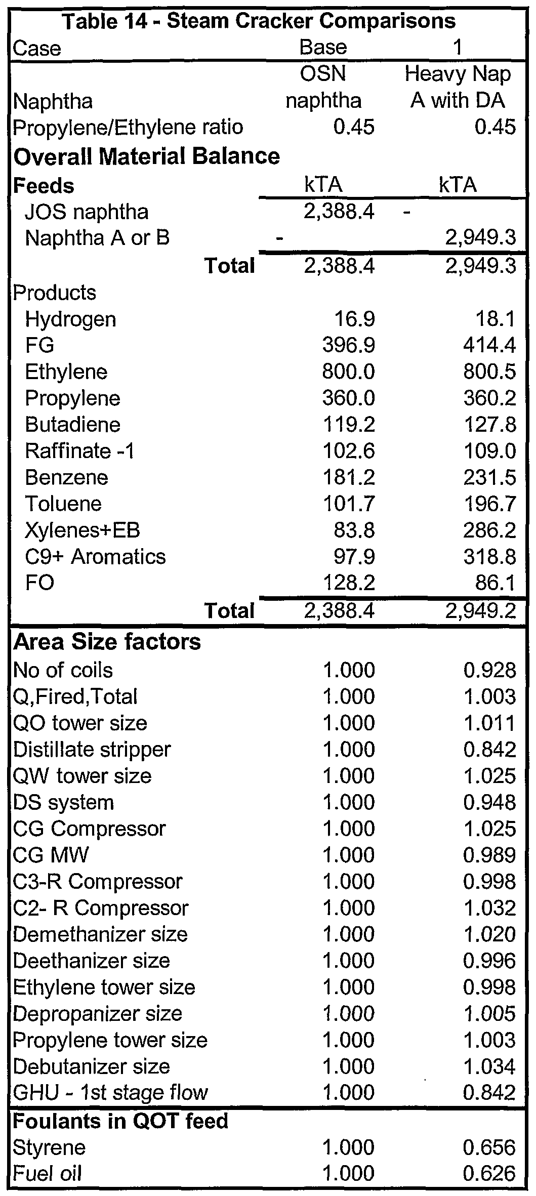
[0085] EXAMPLE 12: Table 14 shows the advantages for dearomatizing
the heavy naphtha A feedstream for the production of ethylene at a
propylene:ethylene ratio of 0.45. Table 14 shows comparisons of overall
material balance, the major equipment sizes, and fouling compounds present in
the quench oil tower feed feed of grade naphtha feed ethylene plant versus a
dearomatized heavy naphtha A feed ethylene plant operating at a P/E ratio of
0.45.
[0086] Table 14 comparison shows that dearomatized heavy naphtha A,
having no aromatics present, produces approximately 63% of the fuel oil
produced from an OSN naphtha feedstock, and that the fuel oil stripper is no
longer a limiting factor to the ethylene capacity. The largest equipment size
factor for the dearomatized heavy Naphtha A feed is 1.03 for the ethylene
compressor, implying that the ethylene plant will be able to operate at 97%
ethylene capacity using dearomatized heavy naphtha A feed as compared to
using OSN naphtha feedstock.
[0087] For a dearomatized heavy naphtha A feed, of the present example,
styrene and fuel oil production can be approximately 63% of that of the OSN
naphtha feed, indicating that quench oil tower fouling should be reduced when
dearomatized heavy naphtha A is used in the cracking process instead of the
grade naphtha.
[0088] Numerous embodiments and alternatives thereof have been
disclosed. While the above disclosure includes the best mode belief in carrying
out the invention as contemplated by the inventors, not all possible alternatives
have been disclosed. For that reason, the scope and limitation of the present
invention is not to be restricted to the above disclosure, but is instead to be
defined and construed by the appended claims.