WO2004015703A1 - Optical disk - Google Patents
Optical disk Download PDFInfo
- Publication number
- WO2004015703A1 WO2004015703A1 PCT/JP2003/009943 JP0309943W WO2004015703A1 WO 2004015703 A1 WO2004015703 A1 WO 2004015703A1 JP 0309943 W JP0309943 W JP 0309943W WO 2004015703 A1 WO2004015703 A1 WO 2004015703A1
- Authority
- WO
- WIPO (PCT)
- Prior art keywords
- thickness
- optical disk
- substrate
- optical disc
- recording
- Prior art date
Links
Classifications
-
- G—PHYSICS
- G11—INFORMATION STORAGE
- G11B—INFORMATION STORAGE BASED ON RELATIVE MOVEMENT BETWEEN RECORD CARRIER AND TRANSDUCER
- G11B7/00—Recording or reproducing by optical means, e.g. recording using a thermal beam of optical radiation by modifying optical properties or the physical structure, reproducing using an optical beam at lower power by sensing optical properties; Record carriers therefor
- G11B7/24—Record carriers characterised by shape, structure or physical properties, or by the selection of the material
- G11B7/24018—Laminated discs
- G11B7/24027—Layers; Shape, structure or physical properties thereof
-
- G—PHYSICS
- G11—INFORMATION STORAGE
- G11B—INFORMATION STORAGE BASED ON RELATIVE MOVEMENT BETWEEN RECORD CARRIER AND TRANSDUCER
- G11B7/00—Recording or reproducing by optical means, e.g. recording using a thermal beam of optical radiation by modifying optical properties or the physical structure, reproducing using an optical beam at lower power by sensing optical properties; Record carriers therefor
- G11B7/24—Record carriers characterised by shape, structure or physical properties, or by the selection of the material
- G11B7/2403—Layers; Shape, structure or physical properties thereof
- G11B7/24056—Light transmission layers lying on the light entrance side and being thinner than the substrate, e.g. specially adapted for Blu-ray® discs
-
- G—PHYSICS
- G11—INFORMATION STORAGE
- G11B—INFORMATION STORAGE BASED ON RELATIVE MOVEMENT BETWEEN RECORD CARRIER AND TRANSDUCER
- G11B7/00—Recording or reproducing by optical means, e.g. recording using a thermal beam of optical radiation by modifying optical properties or the physical structure, reproducing using an optical beam at lower power by sensing optical properties; Record carriers therefor
- G11B7/24—Record carriers characterised by shape, structure or physical properties, or by the selection of the material
- G11B7/2403—Layers; Shape, structure or physical properties thereof
- G11B7/24035—Recording layers
- G11B7/24038—Multiple laminated recording layers
Definitions
- the present invention relates to an optical disk, and more particularly, to an optical disk that includes a substrate, a recording layer, and a protective layer, and is irradiated with laser light from the protective layer side.
- the portable information recording processing terminal has a compact size from the viewpoint of convenience, the disk size of the optical disk used must be small.
- the recording capacity of data that can be recorded per disc must be large.
- the wavelength of the recording or reproducing laser beam is shortened, and the recording or reproducing laser beam is focused on the optical disk.
- a method of increasing the number of apertures (NA) of the objective lens is generally used. Based on such a method, for example, a laser beam for recording or reproduction
- the NA of the objective lens is 0.78 or more. It is the structure that is.
- optical discs used in portable information recording and processing terminals are exposed to severe temperature and humidity changes due to environmental changes caused by carrying. For this reason, optical disks used in portable information recording and processing terminals must have a small amount of disk warpage due to changes in temperature and humidity.
- An object of the present invention is to provide a novel optical disk that can solve the problems of the conventional technology as described above.
- An optical disc according to the present invention comprises: a substrate having a diameter larger than 50 mm; a recording layer provided on the substrate; and the substrate provided so as to be laminated on the recording layer, on which a laser beam for recording or reproduction is incident. It has a thinner protective layer, and the overall thickness is 0.7 mm or more.
- Another optical disk according to the present invention has a substrate having a diameter of about 80 mm, a recording layer provided on the substrate, and a thickness provided on the recording layer so as to be laminated on the recording layer, on which a laser beam for recording or reproduction is incident.
- the protective layer has a thickness of 0.1 mm and the overall thickness is 0.94 mm or more.
- Still another optical disc according to the present invention is provided with a substrate having a diameter of about 50 mm, a recording layer provided on the substrate, and a recording layer, and a recording or reproducing laser beam incident thereon.
- the protective layer has a thickness of 0.1 mm and the overall thickness is 0.7 mm or more.
- Still another optical disc according to the present invention is provided with a substrate having a diameter of approximately 51.5 mm, a recording layer provided on the substrate, and a laser beam for recording or reproducing.
- a protective layer having a thickness of 0.08 mm to be incident is provided, and the overall thickness is at least ⁇ .8 mm.
- Still another optical disc according to the present invention is provided with at least a substrate, a recording layer having a single-layer structure or a multi-layer structure provided in a state of being laminated on the substrate, and provided so as to be laminated on the recording layer for recording or reproducing. And a protective layer that is thinner than the substrate on which the laser light is incident.
- the substrate and the recording layer are formed so as to satisfy the following conditions. f: El (y) e (y) dy + J ni E2 (y) e (y) dy
- y displacement in the thickness direction of the optical disc
- m represents each layer constituting the optical disc.
- e (y) represents the distortion generated in the optical disk.
- E 0 represents the initial strain of the optical disc
- FIG. 1 is a cross-sectional view illustrating a schematic configuration of an optical disc according to the present invention.
- FIG. 2 is a diagram showing the relationship between the disk diameter of the optical disk and the disk thickness of the optical disk obtained by the optical disk manufacturing method according to the present invention.
- FIG. 3 is a schematic configuration diagram showing an apparatus for measuring the maximum amount of warpage of an optical disk at a predetermined disk thickness.
- an optical disc 1 has an information recording / reproducing layer 12 formed on a substrate 11 and a protective layer 13 formed on the information recording / reproducing layer 12 .
- Each of the information recording / reproducing layer 12 and the protective layer 13 may have a single-layer structure or a multilayer structure.
- the information recording / reproducing layer 12 has at least a reflective film and a dielectric It has a structure in which one or more body films and recording films are laminated.
- the recording film constituting the information recording / reproducing layer 12 a film made of a phase-change optical recording material, a magneto-optical recording film, or a recording film containing an organic dye can be used. In the present invention, for example, a film made of a phase-change optical recording material is used as the recording film.
- the thickness of the protective layer 13 provided on the optical disc 1 is 0.1 mm, and the recording / reproducing layer 12 receives laser light having a wavelength of 450 nm or less, for example, 405 nm via the protective layer 13 through the protective layer 13. Is set to 0.78 or more. For example, irradiation is performed in a state of being focused by an objective lens having an NA of 0.8.
- each layer and the disc thickness of the optical disc 1 that is, the thickness of the entire disc, are obtained by using a force balance equation, a moment balance equation, or the like in each layer constituting the optical disc 1.
- each layer constituting the optical disc 1 for example, each layer constituting a multilayer structure when the information recording / reproducing layer 12 or the protective layer 13 has a multilayer structure is also included.
- the balance equation of the force of each layer constituting the optical disc 1 is as the following equation (5).
- eo represents the initial strain of the optical disc 1, and represents the curvature of the optical disc 1.
- the radius of curvature r is 1 /.
- ⁇ represents the amount of warpage of the optical disc 1
- 1 is the width of the portion where the layers constituting the optical disc 1 are stacked, that is, the radial length of the optical disc on which a signal is recorded or on which a signal can be recorded. It represents the degree.
- the disc diameter and the signal is or will be recorded
- the diameter is approximately proportional to the diameter of the optical disk 1
- the maximum allowable value of the warp amount ⁇ of the optical disc is 0.3 degrees.
- the reason why the warp amount of the optical disk is suppressed to 0.3 degrees or less is that if it is 0.3 degrees or less, the influence of aberrations such as coma aberration can be suppressed.
- the thickness of each layer constituting the optical disc 1 and the thickness of the substrate of the optical disc 1 can be obtained.
- the thickness of the substrate 11 is set to 0.1 if the thickness of the protective layer 13 is 0.1 mm. It can be obtained as 6 mm. There is no need to consider the thickness of the recording / reproducing layer 12 because it is sufficiently thinner than the thickness of the substrate 11 and the protective layer 13.
- the substrate 11 having the thickness determined by the above-described method is formed using, for example, an injection molding method or a pressing method using, for example, polycarbonate, polypropylene, or the like.
- the information recording / reproducing layer 12 having a thickness determined by the above-described method is formed on the prepared substrate 11 by, for example, a sputtering method, an evaporation method, a spin coating method, or the like.
- a protective layer 13 having a thickness determined by the above-described method is applied to a material such as an ultraviolet curable resin, polycarbonate, PMMA, amorphous polyolefin, or modified acrylic. It is formed using.
- the protective layer 13 may be formed by bonding a film constituting the protective layer 13 with an ultraviolet-curable resin, an adhesive, or an ultraviolet-curable adhesive.
- the optical disc 1 is completed.
- the optical disk is manufactured using an equation that takes into account the amount of warpage due to temperature and / or humidity changes according to the diameter of the optical disk. Since the thickness of each component layer and the thickness of the entire disc are determined, large warpage does not occur due to changes in the surrounding temperature and humidity, and even in an environment where the surrounding temperature and humidity change.
- An optical disc capable of accurately recording and reproducing information signals can be manufactured.
- FIG. 2 shows the relationship between the disk diameter of the optical disk and the thickness of the entire optical disk determined by the above-described method.
- the optical disk for which the thickness of the entire disk was determined is an optical disk having the structure shown in FIG. 1, in which the thickness of the protective layer is about 0, l mm, and the diameter of the disk is about 12 O mm.
- the optical disk has the same configuration as the optical disk except for the diameter of the disk and the thickness of the entire disk.
- the maximum allowable value of the optical disc warpage ⁇ is 0.3 degrees, and the radial length 1 of the optical disc where signals are recorded or can be recorded is about 60% of the total length, The environment was changed so that the temperature changed by about 50 degrees.
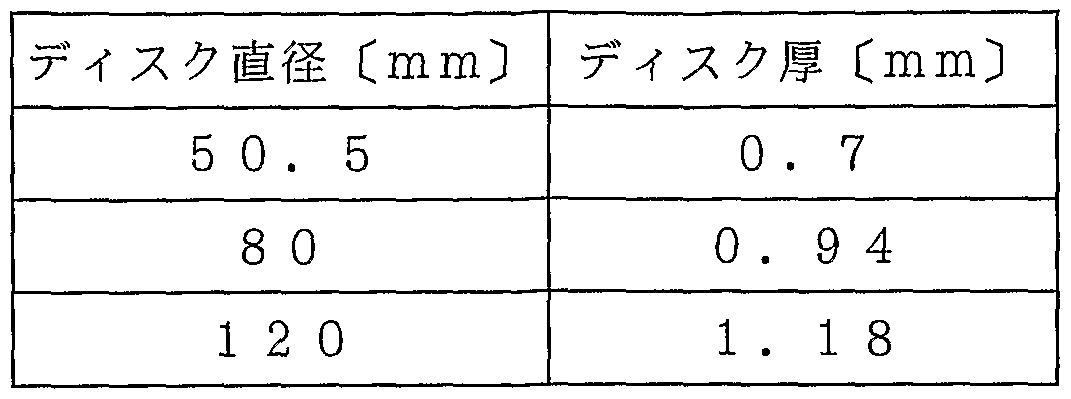
- Table 1 shows the total disk required for the maximum warpage to be 0.3 degrees or less when the disk diameter is 50.5 mm, 80 mm, and 120 mm, obtained using Fig. 2.
- the thickness of the substrate may be 0.6 mm or more.
- the thickness of the substrate 11 at this time may be a value obtained by subtracting the thickness of the protective layer by 0.1 mm from the thickness of the entire disc, that is, 0.94 mm, that is, 0.84 mm or more.
- the maximum amount of warpage of the disk is set to 0.33 degrees in the same manner as in the above example.
- the total thickness of the optical disc 1 that satisfies the following can be obtained from the equation (7) and the like to be 0.8 mm.
- the thickness of the substrate at that time can be obtained as 0.72 mm. .
- FIG. 3 shows an apparatus for measuring the maximum amount of warpage of an optical disk at a predetermined disk thickness.
- the warpage measuring device 20 includes a laser light source 21, a position detection light detector 22, a rotation mechanism (not shown) for rotating the optical disc 1, and a movement (not shown) for moving the rotation mechanism in the radial direction of the optical disk. And a disk hold mechanism (not shown) having a mechanism.
- the laser light emitted from the laser light source 21 is applied to the optical disc 1, and the position where the reflected laser light returns is measured by the position detection light detector 22. Since the position of the laser beam that strikes the position detection photodetector 22 changes according to the amount of warpage of the optical disk 1, the amount of warpage is measured based on the amount of change in the position. In this measurement, the in-circumference average value of the amount of warpage measured by rotating the optical disk 1 once by a rotation mechanism at a predetermined measurement radius is defined as a measurement value at the measurement radius. The position of the measured radius is moved in the radial direction of the optical disk by the moving mechanism of the disk holding mechanism, and the maximum value of the measured value is defined as the maximum warpage of the optical disk 1 having a predetermined disk thickness. 3 009943
- Table 2 shows the measurement results of the maximum amount of warpage measured at each disk thickness by changing the disk thickness of the optical disk, that is, the thickness of the substrate, using the warpage measurement device 2 °.
- the optical disk used for this measurement was a small-diameter disk having a substrate layer, an information recording / reproducing layer, and a polycarbonate protective layer having a thickness of 0.1 mm and a disk diameter of 50.5 mm.
- the temperature around the optical disk was set to 80 degrees and the humidity was set to 85%, and the maximum amount of warpage after 96 hours had elapsed was measured. Table 2
- the maximum warpage is 0.3 degrees or less when the disk thickness is 0.7 mm or more, which is sufficiently small. .
- the disk thickness may be set to 0.7 mm or more.However, the upper limit of the disk thickness is limited from the viewpoint of the amount of warpage due to temperature and / or humidity changes. Not determined.
- the thickness of a small optical disk having a diameter of about 50 mm is determined by using an equation that takes into account the amount of warpage due to temperature and / or humidity changes. mm or more, so that it is used in portable information recording and processing terminals, for example, and is carried around, so that even if the temperature or humidity around the optical disc changes, the optical disc will be greatly warped. Such a situation is eliminated, and accurate information signal recording and reproduction can be performed.
- the present invention has been described with reference to specific configuration examples. However, the present invention is not limited to the above examples, and various modifications are possible.
- an optical disk having a structure as shown in FIG. 1 has been described.
- the present invention can be applied to the optical disk of (1).
- an optical disc having a substrate layer, an information recording / reproducing layer, and a protective layer has been described.
- the present invention can be applied to an optical disc having only the substrate layer and the information recording / reproducing layer.
- the optical disc in which only the substrate layer, the information recording / reproducing layer, and the protective layer are formed has been described, but each layer constituting the optical disc is not limited to these layers.
- the present invention can be applied to an optical disc having an intermediate layer provided between the information recording / reproducing layers.
- the maximum allowable value of the warp amount 0 of the optical disk is 0.3 degrees, but the optical disk has the structure as shown in FIG. If it is not a structure, the maximum amount of warpage may be determined so as to suppress the influence of aberration.
- the disk thickness was determined using an equation that considers the amount of warpage due to changes in temperature and temperature or humidity, and the disk thickness was determined to be 0.994 mm or more.
- optical disk according to the present invention has a large resistance even when the temperature or humidity around the disk changes. Can be prevented from occurring, and can be applied to a small-diameter optical disc to accurately record and reproduce information signals.
Abstract
Description

Claims
Priority Applications (3)
| Application Number | Priority Date | Filing Date | Title |
|---|---|---|---|
| US10/491,980 US7295508B2 (en) | 2002-08-09 | 2003-08-05 | Optical disk |
| EP03784525A EP1528547A4 (en) | 2002-08-09 | 2003-08-05 | Optical disk |
| JP2004527337A JPWO2004015703A1 (en) | 2002-08-09 | 2003-08-05 | optical disk |
Applications Claiming Priority (2)
| Application Number | Priority Date | Filing Date | Title |
|---|---|---|---|
| JP2002232312 | 2002-08-09 | ||
| JP2002-232312 | 2002-08-09 |
Publications (1)
| Publication Number | Publication Date |
|---|---|
| WO2004015703A1 true WO2004015703A1 (en) | 2004-02-19 |
Family
ID=31711825
Family Applications (1)
| Application Number | Title | Priority Date | Filing Date |
|---|---|---|---|
| PCT/JP2003/009943 WO2004015703A1 (en) | 2002-08-09 | 2003-08-05 | Optical disk |
Country Status (7)
| Country | Link |
|---|---|
| US (1) | US7295508B2 (en) |
| EP (1) | EP1528547A4 (en) |
| JP (1) | JPWO2004015703A1 (en) |
| KR (1) | KR20050034588A (en) |
| CN (1) | CN1284161C (en) |
| TW (1) | TWI234780B (en) |
| WO (1) | WO2004015703A1 (en) |
Families Citing this family (1)
| Publication number | Priority date | Publication date | Assignee | Title |
|---|---|---|---|---|
| US8277919B2 (en) * | 2009-07-23 | 2012-10-02 | VMO Systems, Inc. | Reflective coating for an optical disc |
Citations (11)
| Publication number | Priority date | Publication date | Assignee | Title |
|---|---|---|---|---|
| JPS6074136A (en) * | 1983-09-29 | 1985-04-26 | Matsushita Electric Ind Co Ltd | Digital signal recording and reproducing disk and its manufacture |
| EP1127679A2 (en) | 1995-12-20 | 2001-08-29 | Kabushiki Kaisha Toshiba | Information recording medium, method for manufacturing the medium, and apparatus for manufacturing the medium |
| JP2001307381A (en) * | 2000-04-24 | 2001-11-02 | Sony Corp | Optical recording medium |
| JP2001307333A (en) * | 2000-04-18 | 2001-11-02 | Hitachi Maxell Ltd | Optical disk and recording method of optical disk |
| JP2002025109A (en) * | 2000-07-11 | 2002-01-25 | Hitachi Maxell Ltd | Information recording disk |
| EP1187120A2 (en) | 2000-09-05 | 2002-03-13 | TDK Corporation | Optical information medium and its testing method |
| JP2002092962A (en) * | 2000-09-20 | 2002-03-29 | Nec Corp | Optical information recording medium |
| JP2002157783A (en) * | 2000-11-15 | 2002-05-31 | Sharp Corp | Optical information recording medium |
| JP2002157780A (en) * | 2000-11-15 | 2002-05-31 | Sharp Corp | Optical information recording medium |
| JP2002175645A (en) * | 2000-12-06 | 2002-06-21 | Sony Corp | Optical disk |
| JP2002208178A (en) * | 2000-11-06 | 2002-07-26 | Nec Corp | Optical information recording medium, manufacturing method therefor and recording method for optical information recording medium |
Family Cites Families (8)
| Publication number | Priority date | Publication date | Assignee | Title |
|---|---|---|---|---|
| JP3088168B2 (en) * | 1991-12-13 | 2000-09-18 | ティーディーケイ株式会社 | Optical recording medium and manufacturing method thereof |
| JP2990011B2 (en) * | 1994-03-29 | 1999-12-13 | ティーディーケイ株式会社 | Optical recording medium |
| JP3506491B2 (en) * | 1994-06-23 | 2004-03-15 | Tdk株式会社 | Optical information media |
| AU7527098A (en) * | 1997-04-29 | 1998-11-24 | Ciba Specialty Chemicals Holding Inc. | Writable and erasable high-density optical storage media |
| JP3286249B2 (en) * | 1998-05-27 | 2002-05-27 | ティーディーケイ株式会社 | Manufacturing method of optical recording medium |
| US6991863B2 (en) * | 2000-09-04 | 2006-01-31 | Zeon Corporation | Magnetic disk substrate and magnetic disk |
| EP1204109A3 (en) * | 2000-11-06 | 2007-02-21 | Nec Corporation | Optical information recording medium, method of manufacturing the same, and recording method on the same |
| JPWO2002089137A1 (en) * | 2001-04-23 | 2004-08-19 | 松下電器産業株式会社 | Optical information recording medium and optical information recording / reproducing device |
-
2003
- 2003-08-05 JP JP2004527337A patent/JPWO2004015703A1/en active Pending
- 2003-08-05 EP EP03784525A patent/EP1528547A4/en not_active Withdrawn
- 2003-08-05 CN CNB03801274XA patent/CN1284161C/en not_active Expired - Fee Related
- 2003-08-05 KR KR1020047005175A patent/KR20050034588A/en not_active Application Discontinuation
- 2003-08-05 WO PCT/JP2003/009943 patent/WO2004015703A1/en active Application Filing
- 2003-08-05 US US10/491,980 patent/US7295508B2/en not_active Expired - Fee Related
- 2003-08-08 TW TW092121839A patent/TWI234780B/en not_active IP Right Cessation
Patent Citations (12)
| Publication number | Priority date | Publication date | Assignee | Title |
|---|---|---|---|---|
| JPS6074136A (en) * | 1983-09-29 | 1985-04-26 | Matsushita Electric Ind Co Ltd | Digital signal recording and reproducing disk and its manufacture |
| EP1127679A2 (en) | 1995-12-20 | 2001-08-29 | Kabushiki Kaisha Toshiba | Information recording medium, method for manufacturing the medium, and apparatus for manufacturing the medium |
| JP2001307333A (en) * | 2000-04-18 | 2001-11-02 | Hitachi Maxell Ltd | Optical disk and recording method of optical disk |
| JP2001307381A (en) * | 2000-04-24 | 2001-11-02 | Sony Corp | Optical recording medium |
| JP2002025109A (en) * | 2000-07-11 | 2002-01-25 | Hitachi Maxell Ltd | Information recording disk |
| EP1187120A2 (en) | 2000-09-05 | 2002-03-13 | TDK Corporation | Optical information medium and its testing method |
| JP2002157782A (en) * | 2000-09-05 | 2002-05-31 | Tdk Corp | Optical information medium and method for testing the same |
| JP2002092962A (en) * | 2000-09-20 | 2002-03-29 | Nec Corp | Optical information recording medium |
| JP2002208178A (en) * | 2000-11-06 | 2002-07-26 | Nec Corp | Optical information recording medium, manufacturing method therefor and recording method for optical information recording medium |
| JP2002157783A (en) * | 2000-11-15 | 2002-05-31 | Sharp Corp | Optical information recording medium |
| JP2002157780A (en) * | 2000-11-15 | 2002-05-31 | Sharp Corp | Optical information recording medium |
| JP2002175645A (en) * | 2000-12-06 | 2002-06-21 | Sony Corp | Optical disk |
Non-Patent Citations (1)
| Title |
|---|
| See also references of EP1528547A4 |
Also Published As
| Publication number | Publication date |
|---|---|
| KR20050034588A (en) | 2005-04-14 |
| CN1568509A (en) | 2005-01-19 |
| US7295508B2 (en) | 2007-11-13 |
| TW200410240A (en) | 2004-06-16 |
| EP1528547A1 (en) | 2005-05-04 |
| JPWO2004015703A1 (en) | 2005-12-02 |
| US20040246883A1 (en) | 2004-12-09 |
| EP1528547A4 (en) | 2008-07-02 |
| CN1284161C (en) | 2006-11-08 |
| TWI234780B (en) | 2005-06-21 |
Similar Documents
| Publication | Publication Date | Title |
|---|---|---|
| TW594715B (en) | Optical information medium, method of manufacturing for the same, recording or reproducing method for the same and method of inspecting the same | |
| JPH08329523A (en) | Optical disk | |
| WO1999000794A1 (en) | Optical recording medium and optical disk device | |
| JPH0935333A (en) | Optical recording medium | |
| JP3137657B2 (en) | Optical information recording medium and method of manufacturing the same | |
| TW561468B (en) | First-side dual-layer optical data storage disk and method of manufacturing the same | |
| TWI279794B (en) | Optical disc and its manufacturing method | |
| TWI363343B (en) | Optical information recording medium | |
| JP2014035775A (en) | Optical recording medium, and method for manufacturing optical recording medium | |
| TW200406748A (en) | Dual stack optical data storage medium and use of such medium | |
| WO2004015703A1 (en) | Optical disk | |
| US20050013236A1 (en) | Optical disk and optical disk recording and reproducing device | |
| WO2007108507A1 (en) | Multilayer information recording medium | |
| JPH0750035A (en) | Method and apparatus for manufacture of optical disc | |
| JP2000322767A (en) | Optical disk | |
| TW470944B (en) | Optical recording medium and manufacturing method therefor | |
| JP2005243240A (en) | Optical recording medium | |
| JPH05182241A (en) | Optical disk medium | |
| WO2003021591A1 (en) | Method for measuring friction characteristic of surface of optical recording medium | |
| JP2003303444A (en) | Optical disk and manufacturing method thereof | |
| JPH03203825A (en) | Asymmetric double-face optical disk its production, and optical disk device using this optical disk | |
| JP2007207362A (en) | Device and method for recording/reproducing | |
| JP2003077181A (en) | Optical disk | |
| JP2004145974A (en) | Disk drive | |
| US20050232126A1 (en) | Optical data storage medium and use of such medium |
Legal Events
| Date | Code | Title | Description |
|---|---|---|---|
| AK | Designated states |
Kind code of ref document: A1 Designated state(s): CN JP KR US |
|
| AL | Designated countries for regional patents |
Kind code of ref document: A1 Designated state(s): AT BE BG CH CY CZ DE DK EE ES FI FR GB GR HU IE IT LU MC NL PT RO SE SI SK TR |
|
| WWE | Wipo information: entry into national phase |
Ref document number: 2004527337 Country of ref document: JP |
|
| WWE | Wipo information: entry into national phase |
Ref document number: 2003784525 Country of ref document: EP |
|
| WWE | Wipo information: entry into national phase |
Ref document number: 10491980 Country of ref document: US |
|
| WWE | Wipo information: entry into national phase |
Ref document number: 1020047005175 Country of ref document: KR |
|
| WWE | Wipo information: entry into national phase |
Ref document number: 2003801274X Country of ref document: CN |
|
| 121 | Ep: the epo has been informed by wipo that ep was designated in this application | ||
| WWP | Wipo information: published in national office |
Ref document number: 2003784525 Country of ref document: EP |