Link control signalling scheme to introduce new physical layer mode extensions
The present invention relates to a method of signalling link control information concerning the physical layer and/or higher layer features to be transmitted between radio devices of a radio data network. Particularly, the present invention relates to a Data Link Control signalling scheme and a Radio Link Control signalling scheme.
For each data user connection the specific PHY mode, which is specifically related to the used PHYsical layer technology such as adaptive modulation, convolutional coding has to be negotiated depending on the current environment and multi- path propagation channel .
According to the ETSI specifications TS 101 761 -1 (DLC core) and TS 101 761 -2 (RLC sub-layer) the PHY mode for user data channels UDCH (also UMCH, UBCH) are negotiated via RG (resource grant) and RR (resource request) messages. Moreover, once a specific PHY mode has been established for a data user connection (DUC) the LCCH (link control channel) also is used to exchange ARQ and Discard messages, which convey information on the desired PHY mode (especially in UL) .
Prior to establishment of user data connection, in HIPERLA /2 (H/2) the MT (mobile terminal) needs to associate with an AP (access point) or in the case of an radio or network handover needs to disconnect from the old AP and needs to re-associate with the new AP. The difficulty is that during association and re-association the MT needs to be informed about the LINK-CAPABILITIES of the AP and the AP needs to be informed about the LINK-CAPABILITIES of the MT .
According to the ETSI specifications TS 101 761 -1 (DLC core) and TS 101 761 -2 (RLC sub-layer) the association procedures, the procedures for radio and network handover (sector handover is not relevant within the scope of this invention) are fixed and can be reused. However the exchange procedures of PHY mode information are already included in the current HIPERLAN/2 specification, but currently no means are foreseen to also include information on PHY mode extensions (i.e. the "PHY extension profiles") such as adaptive modulation, turbo codes etc.
In view of that it is the object of the present invention to provide a method for link control signalling which will introduce new features to existing data networks in a modular, flexible manner.
According to the present invention this object is solved by a method according to claim 1. Further favourable developments are defined in the sub claims.
Thus the RG, RR information element (and optionally also the Discard and ARQ messages) may be expanded by PHY extension profile bits, that indicate which new PHY extension profile (or combination of them) are used to expand the H/2 specification. The PHY mode bits (4bit for the LCH and 3bits for the SCH, specified in the ETSI TS 101 761 -1) can be reused and interpreted slightly different e.g. as peak data rate (including the 6, 9, 12, 18, 27, 36, 54 Mbps PHY modes) and hence do not affect the former interpretation of the
SCH/LCH PHY mode field. The abbreviations SCH and LCH are the basic packet formats of the H/2 PHYsical layer identifying the short transport channel (SCH) and the long transport channel (LCH) respectively.
The proposed DLC signalling scheme enables the introduction of new PHY extensions profiles (including also combinations
of different PHYsical layer enhancements) such as adaptive modulation, turbo codes, space frequency block codes. As not all combinations might be useful, depending on the environment and the strength and limitations of each PHY mode extension, it offers the possibility to address also very distinct combinations (for instance the combinations of adaptive modulation and turbo codes only) . One of the major advantages of the proposed signalling scheme is backward compatibility to the existing HIPERLAN/2 specifications.
Also the proposed RLC signalling scheme enables to introduce new PHY mode extensions (including also combinations of different PHYsical layer enhancements) such as adaptive modulation, turbo codes, space frequency block codes. As not all combinations might be useful, depending on the environment and the strength and limitations of each PHY mode extension, it offers the possibility to address also very- distinct combinations (for instance the combinations of adaptive modulation and turbo codes only) . One of the major advantages of the proposed signalling scheme is backward compatibility to the existing HIPERLAN/2 specifications.
Thus, a Data Link Control signalling scheme and a Radio Link Control signalling scheme according to the present invention may introduce a new PHY mode extension to the existing ETSI
HIPERLAN/2 specification in a modular, flexible manner.
The present invention will now be described in more detail in connection with the attached drawings showing in:
Figure 1 a basic MAC frame structure (direct link face optional) for a single sector system;
Figure 2 the mapping between logical channels and transport channels for the downlink;
Figure 3 the mapping between logical channels and transport channels for the uplink;
Figure 4 the mapping between logical channels and transport channels for the direct link;
Figure 5 a FCH structure;
Figure 6 the BRAN HIPERLAN/2 protocol stack in the AP/CC;
Figure 7 the functionality of the RLC sub-layer;
Figure 8 a link capability negotiation;
Figure 9 a radio handover;
Figure 10 a mobile terminated connection setup procedure;
Figure 11 a network handover procedure;
Figure 12 a mobile terminated connection setup procedure;
Figure 13 a mobile originated connection setup procedure; and
Figure 14 a signalling concept and PHY extension profiles for HIPERLAN/2.
The following examples are preferred embodiments of the present invention. They are described as HIPERLAN/2 applications, but the present invention is not limited thereto and may also be applied to IEEE applications.
Please note, that a list of acronyms and abbreviations is given at the end of the description and the terms "PHY extension profiles" and "PHY mode extensions" will in the following be used synonymously and are different from the "PHY mode". Whereas the "PHY mode" denotes a certain peak
date, the "PHY extension profile" determines the PHY layer technology and/or higher layer technology applied to deliver aforementioned peak data rate.
The principle of the DLC signalling scheme according to the present invention shall be explained by the following example :
N spare bits shall be used as "PHY extension profile identifier" to address 2N PHY extension profiles for instance via N=3 bits, that are already available in the RG and RR information elements of the DLC core specification, to enable the use of the PHY mode extension for data user traffic mainly (UDCH) . Furthermore, 1 spare bit shall be used for optimising the ARQ procedure for the PHY mode extensions as well (please note: optimising ARQ can be considered as optional) . The interpretation of the former SCH/LCH PHY mode bits is slightly modified from representing a combination of modulation and coding scheme into representing a peak data rate. According to this invention each PHY mode extension profile is labelled by a so-called "PHY extension profile identifier". The PHY mode is labelled by the "PHY mode identifier" .
FCCH: Expanding the RG information element does not affect the former interpretation of the LCH PHY mode field as peak data rate e.g. the 6, 9, 12, 18, 27, 36, 54 Mbps PHY mode. By introducing the N=3 new bit to indicate which PHY mode extension (or combination of them) is used, the specification is only expanded.
LCCH:
Expanding the RR information element does not affect the former interpretation of the LCH PHY mode field as peak data rate e.g. the 6, 9, 12, 18, 27, 36, 54 Mbps PHY mode. By introducing the N=3 new bit to indicate which PHY mode
extension (or combination of them) is used, the specification is only expanded.
For the ARQ message it is desirable especially in uplink to indicate the AP whether the PHY mode should be selected more robust or whether this is not needed. For this reason in the current H/2 specification the ARQ message in UL contains a LCH PHY mode field which indicates the PHY mode in terms of the peak data rate. The LCH PHY mode can still be used in the former way, as it can be assumed that the PHY mode extension (or the combination of PHY mode extensions) selected at DUC connection setup can be maintained e.g. remains unchanged unless not explicitly signalled. The interpretation of the LCH PHY mode field remains unchanged in terms of the peak data rate, still allowing to control PHY mode robustness. In some cases it might be feasible to switch on/off a certain PHY mode extension. In this case 1 spare bit (already- available in the current H/2 specification) can be used to indicate, that a change/modification in the selection of the used PHY mode extension is desired by the MT. The optimal case is to have additional N=3 spare bits available also for the ARQ message in order to indicate a specifically desired PHY extension profile, but however 1 spare bit will also work.
The LCH PHY mode field of a Discard messages is handled accordingly for the interpretation in the ARQ message.
Now the principle of the RLC signalling scheme according to the present invention will be explained.
The invention has an impact on at least 3 RLC functional entities :
1. Association Control Function (ACF) , 2. Radio Resource Control (RRC)
3. Data User Connection Control (DUCC)
The functional entities of the RLC sub-layer can be divided up into RRC (Radio Resource Control) , ACF (Association Control Function) and the DUCC (Data User Connection Control) functional entity. Each functional entity is included in a MT and an AP. They communicate via the RLC messages as specified in the RLC sub-layer specification. An essential aspect here is to extend the available RLC functionality by additional features, capable to address and control HIPERLAN/2 PHY mode extensions .
According to this invention, the modification of the current HIPERLAN/2 (H/2) specification encompass the ACF, the RRC and the DUCC.
1. ACF functional entity:
The mobile terminal (MT) and access point (AP) shall inform each other that PHY mode extensions are available and which specific PHY mode extensions are supported. In more detail information on the available/supported set of PHY mode extensions has to be exchanged between the MT and the AP. The set of supported PHY mode extensions is labelled by a so- called "PHY extension profile set identifier". In particular this "PHY extension profile set identifier" must not necessarily be the same (or assign the same) as the "PHY extension profile identifier". Moreover, if the M bits are used for the "PHY extension profile set identifier" and N bits for the "PHY extension profile identifier" then the condition M >= N should hold. It shall be noted, that as a result of the association procedure only the set PHY mode extensions common to that specific MT and AP will be determined. Which specific PHY mode extension is later on used for user data exchange is negotiated separately by means of the RG and RR information elements defined by the DLC specification.
Association procedure:
Note, that during association the "PHY extension profile set identifier" is exchanged. la) MT to AP: send RLC-LINK-CAPABILITY message to indicate availability of specific PHY mode extensions (M bits) supported by the MT. lb) AP to MT: send RLC-LINK-CAPABILITY-ACK message to acknowledge availability (M bits) of PHY mode extensions, that are supported by the AP.
2. RRC functional entity:
Either a sector, radio or network handover has to be performed. To achieve this, the MT and AP do not only have to know about the availability the supported set of PHY mode extensions, but they also have to negotiate and agree one single PHY mode extension, which is supported by both AP and MT, and which will be used for the ongoing user data connection after handover. In more detail the ongoing connection has to be switched off from the old AP and be connected to the new AP, potentially already using one (single) of the supported PHY mode extensions for the user data traffic.
Sector handover procedure:
The sector handover is a trivial case and nothing has to be done as the MT doesn't need to be reattached to a new AP.
Radio handover procedure:
A radio handover is defined by the movement from one MT from the old AP to the new AP, whereas old AP and new AP are connected via a common Central Controller (CC) . Thus it can be assumed that the new AP already is informed about the details of the PHY mode extensions supported by the MT and the radio resource control includes the steps of: 2a) MT to new AP: send RLC-HANDOVER-REQUEST message (the same as in HIPERLAN/2)
2b) new AP to MT: send RLC-RADIO-HANDOVER-COMPLETE message, including the new set of PHY mode extensions i.e. the "PHY
extension profile identifier" between MT and new AP, respectively the new PHY mode extension, which is going to be used next to convey user data traffic.
Network handover procedure:
A network handover is defined by the movement from one MT from the old AP to the new AP, whereas old AP and new AP are NOT connected via a common Central Controller (CC) . Thus it can NOT be assumed that the new AP already is informed about the details of the PHY mode extensions supported by the MT. Therefore, the following messages have to be exchanged: 2c) MT to new AP: send modified RLC-LINK-CAPABILITY message to the new AP, including the set of PHY mode extensions supported by the MT 2d) new AP to MT: send RLC-NETWORK-HANDOVER-COMPLETE message, including the new set of PHY mode extensions i.e. the "PHY extension profile identifier" between MT and new AP, respectively the new PHY mode extension, which is going to be used next to convey user data traffic.
3. DUCC functional entity:
The MT already is associated to an AP e.g. already has a per cell unique MAC-ID, but no user data are transmitted. Thus, the following messages have to be exchanged: 3a) TX to RX: send RLC_SETUP message from the sender (TX) to the receiver (RX) to convey PHY mode extension bits (i.e. the "PHY extension profile set identifier"), indicating what specific PHY mode extensions are supported by the sender (TX) 3b) RX to TX: send RLC_CONNECT message from the receiver (RX) to the sender (TX) to inform the TX about the PHY extension modes supported in the RX i.e. the complete set of supported PHY extension profiles.
3c) TX to RX: If the sender (TX) accepts the PHY mode extensions indicated in the RLC_CONNECT message, then the TX shall send the RLC_CONNECT_ACK message to confirm the selection. If the TX does NOT accept the PHY mode extensions
it shall respond with the RLC_RELEASE message (no connection setup will be done) .
Please note, that the sender (TX) and the receiver (RX) could be both, either the AP or the MP.
The Unicast DUC Setup procedure is described in the following. If the receiver of the RLC_SETUP message is not able to accept the proposal made by the sender, it shall send RLC_CONNECT message containing the receivers proposal. To accept the proposal made by the sender, the receiver shall repeat the proposal of the AP in the RLC_CONNECT message. If the sender accepts receiver's proposal sent in the RLC_CONNECT message, the sender shall respond with RLC_CONNECT_ACK message. Otherwise the sender shall send
RLC_RELEASE message and continue with the Release procedure.
Generally, the RLC signalling procedures use the "PHY extension profile set identifier" to exchange/negotiate a set of PHY extension profiles, that are supported commonly by AP and MT in centralized mode and by the connected MT's in direct link mode.
The DLC signalling procedures use the "PHY extension profile identifier" and the "PHY mode identifier" to address a specific nominal data rate (e.g. the used PHY mode) , that is used for running user data connections.
The following table 1, table 2 and table 3 show a specific example of such "PHY extension profile set identifiers", "PHY extension profile identifiers" and "PHY mode identifiers".
Table 1: PHY extension profile set identifier and corres onding PHY profiles
Table 2: PHY extension profile identifier and corresponding PHY profile
Table 3 : PHY modes and corresponding PHY mode identifiers and peak data rates
Standardization concept to introduce PHY mode extensions to HIPERLAN/2
In the following an application of the present invention related to the HIPERLAN/2 (H/2) standard will be described.
However, the present invention is not limited to HIPERLAN/2 applications .
Introduction
The previously mentioned ETSI BRAN HIPERLAN/2 standard can only cope with very limited terminal ranges and speeds. Specific air interface enhancements especially on the PHYsical layer will enable a significantly higher terminal range and mobility, from typical wireless LAN operation style of less than 3km/h and 50m to significantly higher ranges and speeds .
In order to support these requirements, not only enhanced PHYsical layer technologies such as multiple antenna concepts, adaptive modulation, turbo codes, enhanced pilot patterns for channel tracking support have to be provided, but also the an DLC/RLC signalling scheme, which enables HIPERLAN/2 devices to exchange information on the availability and to negotiate the usage of certain PHY mode extension technologies.
Scope
The following sections are focusing on the impact of HIPERLAN/2 physical layer mode extensions on the Data Link
Control (DLC) core [1] and Radio Link Control (RLC) sub-layer specification [2] with respect to the required signalling.
Discussion of the Data Link Control (DLC) Layer specification - Part 1: Basic Data Transport Functions (ETSI TS 101 761 - 1 vl.2.1)
HIPERLAN/2 MAC Frame In a HIPERLAN/2 system the Medium Access Control (MAC) frame usually (for ITx and IRx antenna) consists of the sequence of BCH, FCH, ACH, DL phase, an optional DiL phase, UL phase and some RCH's as depicted in Figure 1. The H/2 MAC structure has been optimised for high speed packet data, deploying a Time Division Duplex / Time Division Multiple Access (TDD/TDMA) scheme, capable to allocate resources on demand, if required also in an asymmetric manner. The main information on the MAC frame structure is conveyed via the BCH, FCH and ACH transport channels periodically, in each MAC frame.
Transport channels
Table 4 gives an overview on the transport channels and the corresponding PHY modes .
Table 4: Characteristics of Transport channels
Table 5: Set of the supported PHY modes for different transport channels
Each transport channel can be send with an specific PHY (Physical) layer mode, which is defined by a combination of modulation level and coding rate, thus resulting in a unique peak data rate i.e. nominal data rate, which can be considered a unique PHY mode descriptor.
Mapping of logical channels to transport channels
The mapping of the logical channels to the transport channels, as the basic transport mechanism, is shown in Figure 2 for the down link, Figure 3 for the uplink and Figure 4 for the direct link. According to the H/2 specification the UDCH, UBCH and UMCH channels are considered to convey almost user data.
Overview of the FCCH, LCCH and ASCH messages
In each MAC frame at least one information element (IE) is used per active connection (defined by destination MAC-ID and DLCC-ID) to indicate especially the start position, PDU train structure and length, and the PHY mode of the SCH sequence and LCH sequence, that are used to convey data in DL, UL and DiL phase. These IE's are transmitted via the FCCH logical channel and are mapped physically into the FCH transport channel, the structure of which is shown in Figure 5.
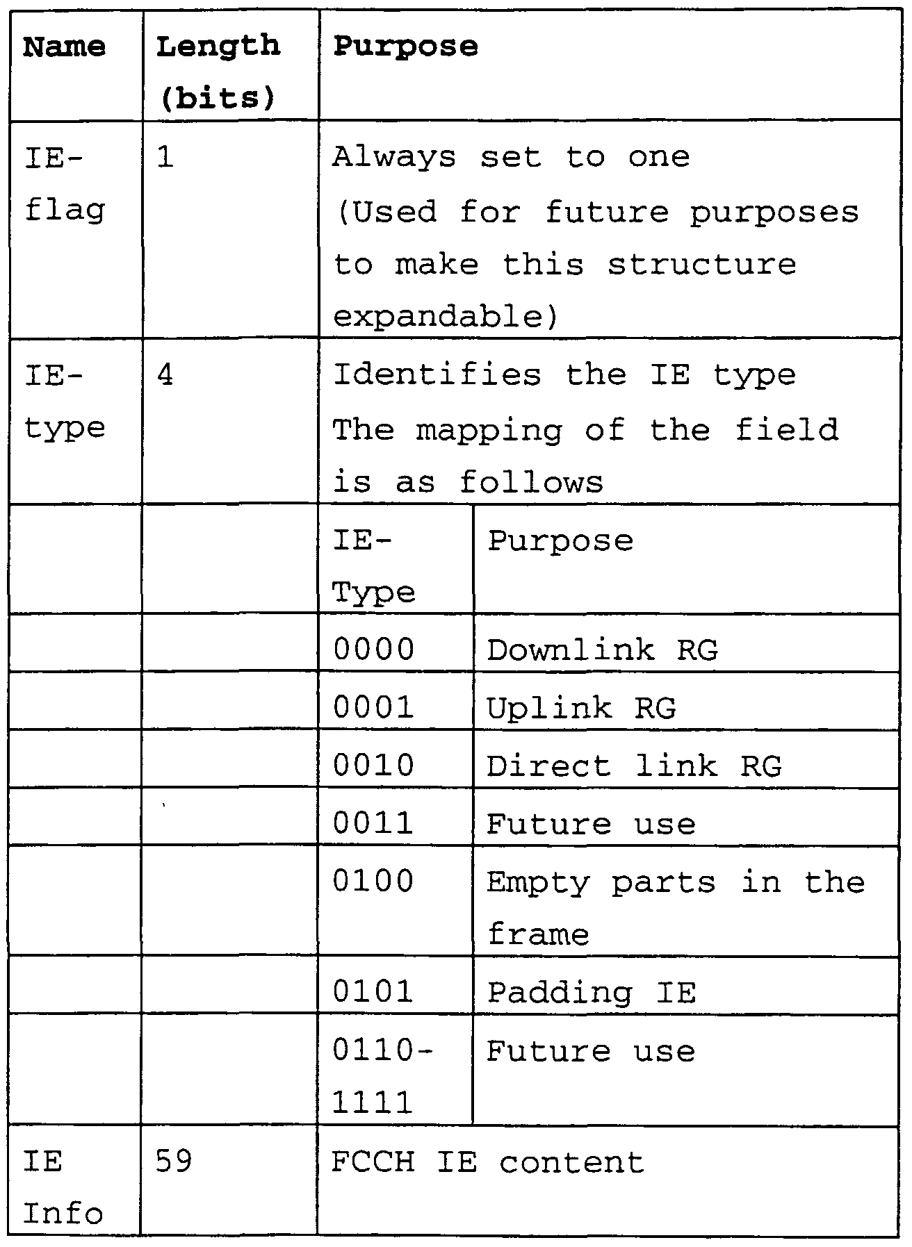
The overview on the content of an IE is shown in the following, according to Table 6:
Table 6 : Contents of the FCH IEs
The content of the RG IE Info field is sent in DL/UL and DiL phase and are shown in Table 7, 8 and 9:
Table 7: Format of RG IE for downlink allocation in centralized mode
Table 8: Format of RG IE for the uplink allocation in centralized mode
Table 9: Format of RG IE for direct link (optional feature)
As it can also be seen from Table 6, that the IE-flag of each IE indicates the syntax format of the IE, e.g. it is specified, whether the transmitted information element (IE) is an uplink, downlink or direct link mode Resource Grant (RG) information element. The Resource Request (RR) message can be sent in UL phase or DiL phase and is conveyed in a SCH
or LCH transport channel. The RR message is shown in Table 10 and 11 :
Table 10: Contents of the RR message for uplink
Table 11: Contents of the RR message for direct link
DLC layer conclusions for H/2 PHY extension profiles
The following Table 12 gives an overview on the logical channels, that are involved in transporting PHY mode signalling. The logical channels conveying PHY-Mode information are marked bold italic.
Table 12: Overview on the logical channels
The most significant logical channel conveying PHY mode information is the FCCH. The RG information element in HIPERLAN/2 is a basic means to flexibly adjust the MAC frame structure to the offered traffic load and the channel conditions. Therefore if PHY mode extensions are intended to be included in the set of HIPERLAN/2 specifications, it is
strictly required to expand/modify the RG-IE in a backward compatible manner. As it can be seen from Table 12, there are 3 unused bits left, common to the DL, UL and DiL, that might be used to introduce PHY mode extensions. The advantage of this solution is, that a larger number of PHY extensions could be addressed such as AM, TC, SFBC including also other extensions not enlisted here could be used with all available peak data rates (6, 9, 18, 27, 36 and 54Mbps see Table 13). As not all combinations of PHY mode extensions might be useful very specific combinations of PHY mode extensions might explicitly be addressed by means of certain bit patterns, in a backward compatible way. A further possibility is to make use of the unused PHY mode combinations of the LCH channel, resulting in one more free bit, which potentially could be combined with the other remaining free bits enlisted in Table 12. However, this solutions breaks the design philosophy of the H/2 specification, because it additionally needs further bits which are not available in the LCH PHY mode identifier, this solution will not be considered furthermore.
It can also be seen, that in the current H/2 specification already 3 bit are reserved to address SCH PHY modes and 4 bits are specified to address LCH PHY modes (even if not all bit combinations are used to address a specific PHY mode) .
Each PHY mode is specified by a modulation level and a coding scheme, thus being described sufficiently by means of a peak data rate, according to Table 13.
Table 13 : PHY mode dependent parameters
As a consequence of the equivalence of a specific PHY mode and the nominal bit rate i.e. the peak data rate, the selection of a PHY mode and a specific PHY mode extension technology corresponds to the selection of a peak data rate and a set of descriptors for the used physical layer technology, enhancing H/2. In this context these
"descriptors" are required to determine the specific PHY mode extension technology which is used to deliver the nominal data rate. Here the nominal data rate represents the sane as the PHY mode identifier specified in H/2, please see also [2]. The current H/2 specification reserve 4 bit for LCH PHY modes and 3 bit for SCH PHY modes, whereas not all bit combinations are used yet. These free combinations might be used to address specific PHY modes for instance to support higher terminal velocities or new peak data rates, different from the ones, currently specified in H/2, applicable in the case that the pilot pattern, required for channel tracking, change the nominal bit rate (note that also different solutions might exist) .
Accordingly to the ETSI TS 101 761-1 vl .2.1 pages 18, 24 an UDCH channel (which is mapped into a LCH channel only) is used to transmit user data between AP/MT's and vice versa. The UDCH is explicitly defined by the MAC ID(s) and the DLCC ID. The resources assigned to a DUC (Data User Connection) are conveyed in the RG (resource grant) message send in the FCCH. Please note, that no MAC ID and no DLCC ID is included in the actually transmitted UDCH, but user data only. One of the basic assumptions to include PHY mode extension into the H/2 specification is to enable usage of more robust data transmission and thus to reduce the affordable interference level whilst the throughput is optimised. In this case mostly the LCH channels e.g. the UDCH, UBCH and UMCH are required to support the PHY mode extensions.
Please note, that the IE elements contain an IE flag which is always set to "1". This flag has intentionally been included without being used at this stage, in order to make the HIPERLAN/2 MAC frame structure expandable. Most probably this flag has been introduced as a marker for major changes in the MAC frame structure, possibly referencing complete new transport channels rather than only referencing new types of IE messages capable to address new PHY modes. Therefore this approach might be considered as very unlikely to be accepted within the HIPERLAN/2 standardization community to indicate usage or availability of PHY mode extensions - besides the fact that from a technological point of view it does not solve the problem of having to less bits and to many PHY mode extensions to be supported, which makes this approach unpractical. Therefore this approach will not be considered in more detail .
The DCCH logical channel is used to convey RLC information, including also the transport of information on the link capabilities of a HIPERLAN/2 device, such as whether the optional 64QAM is supported. As the specification of these
RLC information exchange is not part of the H/2 DLC specification it will not be considered here, but later on within the scope of chapter " Discussion of the Data Link Control (DLC) Layer specification - Part 2: Radio Link Control (RLC) sub-layer (ETSI TS 101 761 - 2 vl .1.1 ) " .
During the association procedure ETSI TS 101 761-2 vl .1.1 pages 17,18 between an AP and MT an DCCH channel is inherently (without any explicit signalling) established to transport RLC messages. The DCCH logical channel is either mapped to a SCH or a LCH transport channel, each of them being conveyed within a sequence of SCH's and LCH's. Please note, that for the case that the supported PHY mode extensions are already known at the receiver and the sender, the complete sequence of SCH's and/or sequence of LCH's might be transmitted by using PHY mode extensions. During the basic association procedure, where the PHY mode extensions are not yet known in MT and AP, the basic set of HIPERLAN/2 PHY modes shall be used.
The LCCH is either used to send RR (resource request) messages or to exchange ARQ and DISCARD messages respectively. Please note, that the PHY mode information included in the ARQ and Discard messages, conveyed in uplink or direct link phase, is assumed to request a more robust or sometimes less robust PHY mode only. As the exchange of the supported link capabilities between MT and AP, is usually carried out during association phase or at least it can be assumed to be know, it is not strictly required to explicitly signal PHY mode extensions within the ARQ and Discard messages. However as each PHY mode extension might have specific strength and also limitations, it might be useful to indicate the desired PHY mode extension within the resource request (RR) message using for instance additional 3 bits, possibly containing the same syntax and meaning as for the resource grant (RG) messages. For the ARQ messages it might be useful to introduce one additional bit to indicate, that a
change (e.g. to switch on/off) of the used PHY mode extension is desired. However, which PHY mode extension will definitely be used for data transmission is signalled in the RG-IE via FCCH. For the Discard message no modification is required at all.
Discussion of the Data Link Control (DLC) Layer specification
- Part 2: Radio Link Control (RLC) sub-layer (ETSI TS 101 761
- 2 vl.1.1)
Overview of the HIPERLAN/2 protocol stack
In Figure 6 the protocol stack of an HIPERLAN/2 Access Point/Central Controller (AP/CC) is depicted. The main difference between the protocol stack of an MT and an AP/CC is, that for the MT contains only one Error Control (EC) , only one RLC and only one MAC instance.
RLC Service primitives The communication procedure between an AP/CC and a MT is handled in a peer to peer manner. The message exchange procedure is completely defined by the definition of the content of the service primitives and by the flow chart of the message exchange procedures of these primitives, that are send peer to peer between functional instances of the same type.
DLC C-SAP primitives with their corresponding RLC primitives:
Table 14: RLC service primitives
RLC functional entities
The division of functional entities of RLC sub-layer is informative. From the perspective of functionality they have been divided to four groups in this specification according to Figure 7 :
1. Association Control
2. Radio Resource Control
3. DLC User Connection Control 4. Basic RLC transport machine
Association Control, DLC Connection Control and Radio Resource Control are involved to some extent into the exchange of the supported features and functionality of MT and AP . In the following the message exchange procedures that are considered to be relevant for the transport PHY mode information will be discussed in more detail.
Association procedure During the association procedure the link capability negotiation is performed (RLC specification [2] page 18, 23) as shown in Figure 8 by using the RLC-LINK-CAPABILITY, RLC-LINK-CAPABILITY-ACK messages. During association procedure the RLC-LINK-CAPABILITY message shall be used to inform the AP about the link capability features of the MT. The AP shall select from the link capabilities of the MT and shall add its own link capabilities to the RLC-LINK- CAPABILITY-ACK message and send it to the MT. The MT will continue with the association procedure if it accepts the received link capabilities. To introduce PHY mode extensions, detailed link capabilities information is mainly required for the network handover procedure to explicitly signal the LINK- CAPABILITIES of the MT to the new AP. In the case of a radio handover no explicit signalling is required, because it can be assumed that the link capabilities of the MT are already known in the AP/CC. The RLC-LINK-CAPABILITY-ACK message is considered to be required to be extended in order positively or negatively acknowledge the availability of PHY mode extension.
Radio handover procedure
For the radio handover shown in Figure 9 it is assumed, that the link-capabilities of the MT are already known at the AP/CC and do not need to be transmitted again. During radio handover the RLC-RADIO-HANDOVER-COMPLETE message is used to convey PHY mode capabilities of the new AP to the MT. The corresponding mobile terminated connection setup procedure is shown in Figure 10.
Network handover procedure
During network handover shown in Figure 11 the link capability negotiation procedure as defined within the RLC specification [3] page 65, is carried out and the link capabilities of the MT are conveyed via the RLC-LINK- CAPABILITY message to the new AP. The RLC-HANDOVER-LINK- CAPABILITY-ACK message is used to acknowledge the availability of PHY mode extensions. The link capabilities of the new AP are sent to the MT via the RLC-NETWORK-HANDOVER- COMPLETE message. Please note: during the handover procedure detailed link capability information must be made available from the new AP to the MT and vice versa. Within the scope of network handover procedure the RLC-LINK-CAPABILITY message send from the MT to the new AP must convey the details on the PHY mode extensions supported in the MT. The new AP might reply with a selected set of link capabilities via the RLC- NETWORK-HANDOVER-COMPLETE message .
DUC control setup procedures
During DUC control setup the RLC messages RLC-SETUP and RLC- CONNECT are used to negotiate LINK-CAPABILITY information on the requested SCH/LCH PHY modes and the requested number of SCH and LCH channels to be established for the user data connection, that currently is being set up. Please note, that the RLC-CONNECT-ACK message is not required to acknowledge any PHY mode selections. The corresponding mobile terminated
connection setup procedure and mobile originated connection setup procedure are shown in Figures 12 and 13.
RLC sub-layer conclusions for H/2 PHY extension profiles
During the association procedure as well as during the radio and network handover procedure the LINK-CAPABILITIES including the supported PHY modes are signalled between MT and AP. The knowledge on what PHY modes are supported will enable AP and MT to exchange RR and RG messages accordingly to the supported PHY extension mode capabilities. MT and AP will exchange information on the supported PHY mode extension via the RLC DUCC LCH PDU messages, such as RLC-SETUP, and RLC-CONNECT.
Table 15: RLC message types dealing with PHY mode capabilities and signalling
Some of the RLC messages included in Table 15 are specified to be optional for the RLC sublayer specification, but might be mandatory for the home or business extension profile. Please note, that Table 15 represents a selection of the RLC messages specified in the RLC sub-layer [2], but includes all RLC messages that are relevant within the context of PHY mode extensions .
The Unicast DUC Setup procedure is described in the following. If the receiver of the RLC_SETUP message is not
able to accept the proposal made by the sender, it shall send RLC_CONNECT message containing the receivers proposal . To accept the proposal made by the sender, the receiver shall repeat the proposal of the AP in the RLC_CONNECT message. If the sender accepts receiver's proposal sent in the RLC_CONNECT message, the sender shall respond with RLC_CONNECT_ACK message. Otherwise the sender shall send RLC_RELEASE message and continue with the Release procedure. Please note, that the sender can be both, either the AP or the MP.
As a consequence of the Unicast DUC Setup procedure, where for instance fixed capacity agreements of resources between AP and MT are negotiated, and to take advantage of the benefits of the PHY extensions it is strictly required to include signalling for the PHY mode extensions into the DUC Setup procedures. Please note: If the scope of RLC messages only is to negotiate resources in terms of capacity e.g. data rate, then there is no stringent need to do any modifications. Capacity e.g. data rates can be mapped in implementation specific procedures to the new PHY mode extensions. However it might be more 'consistent' to have the PHY mode extensions also included here. A common set of used PHY mode extensions is negotiated during DUC Setup and may be changed during an active connection. This negotiation on the common set of supported PHY mode extensions is negotiated via the RLC DUCC LCH PDU messages, using the basic H/2 PHY mode schemes. Please note: Link capability negotiation procedure has already been started during association procedure, but no agreement on a common set of PHY mode extensions has been achieved yet. This needs to be completed during the DUC Setup routine. It can be assumed, that usually the link capability negotiation procedure is performed during DUC Setup and that the transmission of detailed link capability information via the RLC-LINK-CAPABILITY message is an exception only required to support network handover.
During association procedure it is useful to generally indicate the availability of PHY mode extensions by sending the RLC-LINK-CAPABILITY message, that shall be acknowledged by RLC-LINK-CAPABILITY-ACK message. To indicate and acknowledge the availability of PHY mode extensions additional 1 bit is sufficient. However, if an efficient network handover procedure is assumed to be supported, where the new AP has no knowledge about the link capabilities of the MT, it is highly recommended to not only indicate the availability of the MT link capabilities, but to also transmit information on which specific PHY mode extensions are supported. In this sense the RLC-LINK-CAPABILITY can, to some extend, be considered as an exception, that requires more than one single additional bit.
Signalling concept to introduce Physical layer Extension Profiles to the HIPERLAN/2 specifications
In order to support different scenarios such as vehicle to vehicle communication and roof-top to roof-top communication scenarios, not only enhanced PHYsical layer technologies including multiple antenna concepts, adaptive modulation, turbo codes, enhanced pilot patterns for channel tracking support have to be provided, but also a DLC/RLC signalling scheme. This signalling scheme is required to enable
HIPERLAN/2 devices to exchange information on the availability and to negotiate the usage of certain PHY mode extensions .
Design principles
A general signalling concept which is intended to be applied to an existing specification - as in this case to HIPERLAN/2 - has naturally to be based on certain design principles. The design principles, which are considered to be most reasonable, are enlisted below:
1. Maximum re-use of the existing HIPERLAN/2 functionality 2. Fully backward compatibility to existing H/2 specifications 3. Re-use of the "extension profile" design concept already in use within HIPERLAN/2
4. No changes on the existing HIPERLAN/2 specifications required
5. Allow usage of different H/2 PHYsical layer extension profiles such as
Enhanced Pilot Patterns, Switched/Multiple Antenna Diversity concepts, Turbo Codes, Adaptive Modulation, Space-Frequency-Block- Codes, ... to be extended as required 6. Flexibility of the design
It is of special interest to realize, that the design principle to support many different PHYsical layer technologies, is also a design goal, due to the fact that each particular PHY technology has it's own strengths and limitations .
Signalling concept
In order to introduce new PHYsical layer mode (PHY mode) extensions profiles to the set of available HIPERLAN/2 (H/2) specifications in a backward compatible manner the signalling concept is proposed to be structured as follows:
Basic DLC/RLC signalling procedures : covering all the functionality required to exchange information about which
PHY extension profiles are supported by a specific H/2 device, negotiate and agree upon which specific PHY extension profile and which PHY mode will be used for user data connections .
PHY extension profile: covering all the functionality required to apply a specific PHYsical layer technology. In
addition to the PHYsical layer functionality also the signalling procedures, that are especially adapted and required for this particular PHY extension profile shall be described herein.
Hence, the signalling concept to support a larger number of PHY extension profiles for HIPERLAN/2 can be flexibly structured as depicted in Figure 14.
Proposed document structure
The first and most basic document could be entitled "Basic DLC & RLC Signalling Procedures for H/2 PHY extension profiles" corresponding to the desired scope and might directly be derived from Figure 14. This document is intended to describe the DLC & RLC signalling procedures that are common to a large set of PHY extension profiles and will thus enable different extensions to be applied as an enhancement to the current HIPERLAN/2 physical layer. The "Basic DLC & RLC Signalling Procedures for H/2 PHY extension profiles" specification should be limited to the signalling which is required for all PHY extension profiles. As depicted in Figur 14 potential PHY extension profiles such as Enhanced Pilot pattern fro channel tracking (EP) , Space Frequency Block Codes (SFBC) , Turbo Codes (TC) and Adaptive Modulation (AM) are intended to be supported.
In order to specify the functionality of a specific PHY mode extension technology it is suggested to have a separate document, entitled "PHY extension profile" functional specification, also easily being derived from the structure depicted in Figure 14. In order to achieve full operation of one single PHYsical layer technology, both "Basic DLC & RLC Signalling Procedures for H/2 PHY extension profiles" and at least one single "PHY extension profile" have to be implemented.
Within the framework of MIND future work is intended to be directed to the previously mentioned specification concept.
Draft proposal for the DLC and RLC signalling of PHY extensions for H/2
Draft extension for DLC functionality
Changes to the RG information element in the FCCH channel
Table 16: Modifications of the resource grant information elements
Note: the spare bits enlisted in Table 16 are used as "PHY extension profile identifiers" .
The FCCH channel conveys information on the structure of the MAC frame, signalled by RG information elements. With 3 additional bits, in the following addressed as "PHY extension bits", it can be signalled which stand alone PHY mode extension (adaptive modulation) or which PHY mode combinations (turbo codes and adaptive modulation) might be used. In total up to 8 different combinations can be addressed in this way. Please note, that the PHY mode field of the SCH's and LCH's remains the same, thus offering the same peak data rates as specified in the H/2 specification including 6, 9, 18, 27, 36, 54 Mbps. However it should be noted, that the same peak data rates as described with the SCH/LCH PHY mode descriptors (e.g. 4 bit for LCH and 3 bit for the SCH PHY mode) are delivered by using different PHY mode extension techniques .
Please note, that in the current H/2 specification already 3 bit are reserved to address SCH PHY modes and 4 bits are used to address LCH PHY modes. As a consequence of the equivalence
of a specific PHY mode and a nominal bit rate e.g. the peak data rate, the PHY mode selection the combination of peak data rate and a set descriptors for the used physical layer transmission schemes including modulation and coding scheme is a sufficient set to extend the number of available PHY modes .
Changes to the RR information element in the LCCH channel
The LCCH channel is used to transmit RR (resource request) information in UL and DiL phase. The same 3 additional "PHY extension bits" shall be used to indicate, that a specific PHY mode (described by the corresponding peak data rate) is requested to be delivered by using specific PHY mode extensions. The semantics of these 3 PHY extensions bits shall be the same as for the RG information elements.
Changes to the ARQ information element in the LCCH channel
There are no changes required in the semantics of the ARQ information element. However the interpretation of the ARQ message changes. Now the bit pattern in SCH/LCH transport field only indicates, that the peak data rate should be increased or decreased, thus controlling the robustness of the PHY mode. It shall inherently be assumed, that the selected combination of PHY mode extensions shall be kept the same during operation.
As an optional feature one spare bit in the ARQ message might be used to indicate a request from the MT to "change the PHY extension constellation" (e.g. switch off/on one or more PHY extensions) . This can either happen to switch off a PHY extension due to power consumption reasons or due to changing channel conditions. Please note, that for the ARQ messages there is one spare bit available and might be used for uplink, downlink and direct link mode.
Changes to the Discard information element
There are no changes to semantics of the Discard information element. However the interpretation of the SCH/LCH PHY mode field shall be changed accordingly to ARQ see section "Changes to the ARQ information element in the LCCH channel".
Draft extension for the RLC sub-layer functionality Changes to the RLC ACF LCH PDU messages
Introduce 3 additional PHY extension bits/flags which indicate, that different PHY extensions such as turbo codes, adaptive modulation, space frequency codes are supported by AP/MT.
Table 17: RLC ACF LCH PDU messages
Please note, that with respect to Table 17, two different alternatives might be possible, the first using "PHY extension bits" and the second using "PHY extension flags" Note: the term "PHY extension flags" in this context is synonymously used with "PHY extension profile set identifier".
• The first alternative introduces M=3 additional "PHY extension bits". By applying "extension bits" to the H/2 RLC specification the same meaning/semantics as the 3 PHY extension bits accordingly to section " Changes to the RG information element in the FCCH channel", should be used. The usage of the same semantics as in the context of the H/2 DLC specification the resource negotiation phase
between AP and MT will have the advantage of simplicity and consistency. In this option the "PHY extension profile set identifier" is equal to the PHY extension profile identifier", e.g. each set contains only one single element.
• Alternatively, denoting the second alternative, the usage of additional M=3 (or 4) flags defined as "PHY extension flags" might be useful. The advantage of this solution is, that during DUC setup, radio and network handover procedures specific PHY mode extension technologies such as AM, TC, SFBC might explicitly be switched on and off, thus introducing a higher flexibility. However in this case an additional table is required to map the RLC "extension flags" to the "extension bits" used within the DLC context. Here the "PHY extension profile set identifiers" mostly contain one are more elements per set identifier.
As both alternatives are very similar, in the following the term "PHY extension bits" will be used to indicate that the second solution is considered to be more convenient. It should be pointed out, that procedures discussed in the following might be applied to both the extension "bit" and the extension "flag" semantic.
The RLC-LINK-CAPABILITY and RLC-LINK-CAPABILITY-ACK messages are send during the association procedure to indicate and acknowledge the link capabilities of an MT, such as the supported PHY mode extensions. The RLC-LINK-CAPABILITY message is sent in uplink and the RLC-LINK-CAPABILITY-ACK is sent in downlink. The RLC-LINK-CAPABILITY-ACK message shall acknowledge only the support/availability of PHY mode extension, specifying them in detail via. M=3 PHY extension bits, which are considered to be sufficient.
Please note: the RLC-LINK-CAPABILITY message is required to sent detailed information on the LINK-CAPABILITIES of the MT to the new AP in order to make this information available for an efficient network handover procedure. As detailed PHY mode information is usually exchanged during the DLC setup procedure, where the RLC_SETUP and RLC_CONNECT messages can be used to negotiate a common set of PHY mode extensions, there is no sufficient reason to have the same functionality included again in the association procedures, unless no network handover has to be supported.
Consequently, the PHY extension bits are set in the RLC-LINK- CAPABILITY message to signal the new AP that at least one specific PHY mode extension is supported by the MT. The AP shall respond with the RLC-LINK-CAPABILITY-ACK message and shall positively or negatively acknowledge the availability of PHY mode extensions in the AP.
Changes to the RLC RRC LCH PDU messages For the RLC-RADIO-HANDOVER-COMPLETE and the RLC-NETWORK- HANDOVER-COMPLETE message the same changes as for the RLC DUCC LCH PDU shall apply.
For the RLC-HANDOVER-LINK-CAPABILITY-ACK message shall be used to acknowledge the availability of a set of supported
PHY mode extensions.
After radio or network handover some of the RLC DUCC LCH PDU messages might be used to re-negotiate the PHY extensions, intended to be sued for the current user data connection
(e.g. UDCH, UBCH, UMCH channels).
Changes to the RLC DUCC LCH PDU messages
Use the RLC-SETUP and RLC-CONNECT messages to exchange detailed LINK-CAPABILI Y information on which combination of PHY extension can be used. Use one bit per additional PHY
extension as a bit to indicate which PHY extension modes are supported. Please note, that also different combinations of PHY extensions may be allowed. The RLC-SETUP is send in uplink or downlink and the RLC-CONNECT message in uplink or downlink.
Table 18: RLC DUCC LCH PDU messages
The PHY extension bits i.e. the "PHY extension profile set identifier" shall be send in the RLC-SETUP and the RLC- CONNECT message to indicate the PHY extension capabilities of the MT and the AP.
Example 1 (Mobile terminated connection setup procedure) : The RLC-SETUP message is sent from the AP to the MT indicating the PHY extension capabilities by using a bit combination for each supported PHY extension or combination of PHY extension. The MT shall respond with the RLC-CONNECT message and shall confirm/acknowledge the supported PHY extension capabilities by using a subset of the PHY extension bits, set in the RLC- SETUP message.
Example 2 (Mobile originated connection setup procedure) : The RLC-SETUP message is sent from the MT to the AP . The RLC- CONNECT message is sent from the AP to the MT. Please note: the procedure is the same as in example one.
All other RLC DUCC LCH PDU messages, that are optional in the RLC core specification, but might be mandatory in either the
home extension or business extension profile may use the same syntax as the RLC-SETUP and RLC-CONNECT messages.
References [1] HIPERLAN/2 Type 2 technical Specification; Physical layer (ETSI TS 101 475 vl .2.2 )
[2] Data Link Control (DLC) Layer specification - Part 1: Basic Data Transport Functions (ETSI TS 101 761 - 1 vl.2.lA)
[3] Data Link Control (DLC) Layer specification - Part 2: Radio Link Control (RLC) sub-layer (ETSI TS 101 761 - 2 vl.2.10
List of Acronyms and Abbreviations
16QAM Quadrature Amplitude Modulation with 16 constellation points
64QAM Quadrature Amplitude Modulation with 64 constellation points
ACH Access Feedback CHannel
AM Adaptive Modulation AP Access Point
APC Access Point Controller
APT Access Point Transceiver
ARQ Automatic Repeat reQuest
ASCH Association Control CHannel BCH Broadcast Channel
BCCH Broadcast Control CHannel
BPSK Binary Phase Shift Keying
BRAN Broadband Radio Access Networks
CIR Carrier to Interference Ratio CL Convergence Layer
CL-SAP Convergence Layer Service Access Point
CPCS Common Part Convergence Sublayer
CRC Cyclic Redundancy Check
DCCH Dedicated Control CHannel DFS Dynamic Frequency Selection
DFT Discrete Fourier Transformation
DiL Direct Link Mode
DL Downlink
DLC Data Link Control DLCC-ID DLC Connection-Identifier
Downlink Used when data are transmitted from the AP to the
MTs
DUC DLC User Connection
ETSI European Telecommunications Standards Institute FCH Frame CHannel
FCCH Frame Control CHannel
FEC Forward Error Correction
FFT Fast Fourier Transformation
H/2 HIPERLAN/2
HIPERLAN/2 High PErformance Radio Local Area Network type
2
IEEE Institute of Electrical and Electronics Engineers
IFFT Inverse Fast Fourier Transform
LAN Local Area Network
LCH Long transport Channel LCCH Link Control CHannel
LSA Load Swapping Algorithm
MAC Medium Access Control
MIND Mobile IP based Network Developments
MT Mobile Terminal OFDM Orthogonal Frequency Division Multiplexing
PDU Protocol Data Unit
PER PDU Error Rate
PHY PHYsical Layer
QAM Quadrature Amplitude Modulation QoS Quality of Service
QPSK Quaternary Phase Shift Keying
RACH Random access Feedback Channel
RBCH RLC Broadcast CHannel
RCH Random Channel RLC Radio Link Control
RSS Radio Signal Strength
SAP Service Access Point
SAR Segmentation And Reassembly
SBLA Simple Blockwise Loading Algorithm SCH Short Transport Channel
SDU Service Data Unit
SFBC Space-Frequency Block Coding
SNR Signal-to-Noise Ratio
SR-ARQ Selective Repeat-Automatic Repeat reQuest SSCS Service Specific Convergence Sublayer
STBC Space-Time Block Coding
TC Turbo Codes
TDD Time Division Duplex
TDM Time Division Multiplexing
UBCH User Broadcast Channel
UDCH User Data CHannel
UMCH User Multicast CHannel
UL Uplink
Uplink Used when data are transmitted from MTs to the AP
VA Viterbi Algorithm
Definitions
For the purposes of the present document, the following terms and definitions apply:
Access Feedback CHannel (ACH) : transport channel where the results of access attempts made in the random access phase of the previous MAC frame is conveyed
Access Point (AP) : device that is responsible for the centralized control of the resources in a radio cell. It is usually connected to a fixed network
Association Control Function (ACF) : group of control functions that use the services of the RLC. These functions are responsible for the handling of the association between MT and AP
Association control CHannel (ASCH) : logical channel in the uplink that conveys new association and re-association request messages
Broadcast CHannel (BCH) : transport channel that broadcasts control information
Broadcast Control CHannel (BCCH) : logical channel that broadcasts control information which is relevant for the current MAC frame
Central Controller (CC) : provides control functionality equivalent to that of an access point but is not necessarily attached to a fixed network. This term is normally used if central controller and MT functionality are located in a single device. It mostly involves direct mode communication
Centralized Mode (CM) : in centralized mode, all data transmitted or received by a mobile terminal pass the access
point or the centralized controller, even if the data exchange is between mobile terminals associated to the same access point or centralized controller
DLC connection: HIPERLAN/2 DLC operates connection oriented. A DLC connection carries user or control data and is identified by a DLC connection identifier. A connection has a set of properties for the transfer of data agreed upon between the MT and the AP or between MT's and a CC
DLC User Connection: DLC user connection is uniquely identified by the DLC connection ID and a MAC ID
DLC User Connection Control (DUCC) : group of control functions that uses the services of the RLC. It is responsible for the handling of DLC user connections
Direct Mode (DM) : data exchange between MTs associated with the same AP or CC takes place without passing but under control of the access point or the central controller
Direct link phase: part of a MAC frame that only contains the data exchanged directly between MTs using direct mode communication methods
Downlink phase: part of the Downlink transmission of a MAC Frame during which user and control data is transmitted from the access point or central controller to mobile terminals. The data transmitted can be user as well as control data in unicast, broadcast and multicast modes
Encryption function: function that is responsible for keeping user data and part of RLC signalling secret between HIPERLAN/2 devices
Error Control (EC) : error control is responsible for detection of transmission errors and, where appropriate, for
the retransmissions. It is assumed that one error control instance is provided per DLC connection
Frame CHannel (FCH) : transport channel that is broadcast and which carries the frame control channel
Frame Control CHannel (FCCH) : logical channel that contains the information defining how the resources are allocated in the current MAC frame. Its content changes in general dynamically from frame to frame
Logical channel: generic term for any distinct data path. A set of logical channel types is defined for different kinds of data transfer services. Each logical channel type is defined by the type of information it carries. Logical channels can be considered to operate between logical connection end points
MAC frame: periodical structure in time that appears on the air interface and that determines the communication of HIPERLAN/2 devices
Mobile Terminal (MT) : device that communicates with an access point or with each other via a radio link. It is typically a user terminal
PDU train: sequence of transport channels delivered to and received from the physical layer
PHY mode: PHY mode corresponds to a signal constellation
(Modulation alphabet) and a code rate combination
Radio cell: radio cell is the area covered by an access point or central controller. It is sometimes used as a term to describe an AP or CC and its associated terminals
Radio Link Control (RLC) sublayer: control plane of the DLC which offers transport services for the radio resource control, association control function and the DLC user connection control
Radio Resource Control (RRC) : group of control functions that use the services of the RLC. It controls the handling of radio resources
Random Access CHannel (RACH) : logical channel in the uplink of the MAC frame in which the MTs can send signalling data for the DLC or the RLC. It is transported in the random channel
Random access Feedback CHannel (RFCH) : logical channel where the result of the access attempts to the random channel made in the previous MAC frame is conveyed
Random CHannel (RCH) : transport channel in the uplink of the MAC that carries the logical channels random access channel and association control channel. A contention scheme is applied to access it
Random Access Phase: period of the MAC Frame where any MT can try to access the system. The access to this phase is based on a contention scheme
Resource Grant (RG) : allocation of transmission resources by an access point or a central controller
Resource Request (RR) : message from a terminal to an access point or central controller in which the current buffer status is conveyed to request for transmission opportunities in the uplink or direct link phase
Sector antenna: term is used to describe if an access point or central controller uses one or more antenna element
Transport channel: basic element to construct PDU trains. Transport channels describe the message format
Uplink phase: part of the MAC frame in which data is transmitted from mobile terminals to an access point or a central controller