WO2003006446A1 - Process for the production of ethers, typically thf - Google Patents
Process for the production of ethers, typically thf Download PDFInfo
- Publication number
- WO2003006446A1 WO2003006446A1 PCT/GB2002/003195 GB0203195W WO03006446A1 WO 2003006446 A1 WO2003006446 A1 WO 2003006446A1 GB 0203195 W GB0203195 W GB 0203195W WO 03006446 A1 WO03006446 A1 WO 03006446A1
- Authority
- WO
- WIPO (PCT)
- Prior art keywords
- feed material
- cycle gas
- zone
- vaporised
- process according
- Prior art date
Links
Classifications
-
- C—CHEMISTRY; METALLURGY
- C07—ORGANIC CHEMISTRY
- C07D—HETEROCYCLIC COMPOUNDS
- C07D307/00—Heterocyclic compounds containing five-membered rings having one oxygen atom as the only ring hetero atom
- C07D307/02—Heterocyclic compounds containing five-membered rings having one oxygen atom as the only ring hetero atom not condensed with other rings
- C07D307/04—Heterocyclic compounds containing five-membered rings having one oxygen atom as the only ring hetero atom not condensed with other rings having no double bonds between ring members or between ring members and non-ring members
- C07D307/06—Heterocyclic compounds containing five-membered rings having one oxygen atom as the only ring hetero atom not condensed with other rings having no double bonds between ring members or between ring members and non-ring members with only hydrogen atoms or radicals containing only hydrogen and carbon atoms, directly attached to ring carbon atoms
- C07D307/08—Preparation of tetrahydrofuran
-
- A—HUMAN NECESSITIES
- A61—MEDICAL OR VETERINARY SCIENCE; HYGIENE
- A61P—SPECIFIC THERAPEUTIC ACTIVITY OF CHEMICAL COMPOUNDS OR MEDICINAL PREPARATIONS
- A61P1/00—Drugs for disorders of the alimentary tract or the digestive system
Definitions
- the present invention relates to the production of ethers, optionally with the co-production of diols and/or lactones by reaction of an organic feed material in the presence of hydrogen.
- the reaction will generally be by hydrogenation and/or dehydration.
- the organic feed material is selected from dicarboxylic acids and/or anhydrides, monoesters of dicarboxylic acids and/or anhydrides, diesters of dicarboxylic acids and/or anhydrides, lactones, a mixture thereof or a mixture of two or more thereof.
- the present invention relates to a process for the co-production of C 4 compounds, more specifically tetrahydrofuran, butane- 1,4-diol and/or ⁇ -butyrolactone from a hydrocarbon feedstock comprising a dialkyl maleate by vapour phase reaction in a hydrogen rich stream.
- it relates to a process for the production of at least 20% of tetrahydrofuran with co-production of butane- 1,4-diol and/or ⁇ -butyrolactone.
- it relates to the production of tetrahydrofuran with any residual butane- 1,4-diol and/or ⁇ -butyrolactone being recycled and converted to further tetrahydrofuran.
- diols by hydrogenation of dialkyl esters of dicarboxylic acids and/or anhydrides, lactones, and mixtures thereof with a minor amount, typically no more than about 10 wt/wt% and preferably no more than 1 wt/wt%, of a monoester ofthe dicarboxylic acid and/or anhydride.
- butane- 1 ,4-diol as the primary product with small amounts, typically up to about 10 mole%, of tetrahydrofuran and up to about 15 mole% of ⁇ -butyrolactone by hydrogenation of a dialkyl ester of maleic acid and/or anhydride, such as dimethyl maleate or diethyl maleate, which may contain minor amounts of dialkyl fumarate and/or dialkyl succinate.
- Dimethyl succinate or diethyl succinate have also been suggested as suitable starting materials for hydrogenation to produce butane- 1,4-diol, tetrahydrofuran and ⁇ -butyrolactone.
- These succinates may be formed by any suitable manner and may be from biotechnology sources.
- dialkyl maleates which are used as feedstock in such hydrogenation processes may be produced by any suitable means.
- the hydrogenation of dialkyl maleates to yield butane- 1 ,4- diol is discussed in detail in US-A-4584419, US-A-4751334 and WO-A-88/00937, which are incorporated herein by reference.
- a dialkyl ester such as dimethyl maleate together with any residual methanol from the esterification reactor, is fed via line 1 to a vaporiser 2 where it is vaporised into a stream of hot cycle gas which is usually pre-heated.
- Cycle gas will normally contain a high concentration of hydrogen gas but may also include other gases including hydrocarbons, carbon oxides, methane, nitrogen. Further, where the cycle gas includes recycled gases from downstream, condensables including product ether, methanol, water, co-products and by-products may also be present.
- the cycle gas is fed to the vaporiser 2 in line 3.
- the combined vaporous stream is then passed in line 4 to the reactor 5 where it is reacted to form butane- 1 ,4-diol, tetrahydrofuran and/or ⁇ -butyrolactone.
- the product stream 6 is cooled and the reaction products are condensed at 7 and separated from the cycle gas before being passed in line 8 to a refining zone 9.
- Recovered cycle gas is compressed and recycled in line 10. Make-up hydrogen will be added to the recovered cycle gas in line 11 with the enriched cycle gas being fed back to vaporiser 2.
- the various products are separated and the butane- 1 ,4-diol is removed in line 12 and the tetrahydrofuran in line 13.
- the ⁇ -butyrolactone, together with the intermediate dimethyl succinate and some butane- 1,4-diol may be recycled in lines 14 and 15.
- the ⁇ -butyrolactone may be partially extracted in an optional refining zone 16 and removed in line 17.
- the methanol water stream separated from the product mix will be recycled upstream via line 18.
- a significant portion ofthe butane- 1,4-diol produced by this or other conventional methods is subsequently converted to tetrahydrofuran.
- This conversion step has substantial cost implications both in investment and operation ofthe plant required for the conversion and as the importance of tetrahydrofuran increases together with its use in derivative applications, it is desirable to provide a process for the production of tetrahydrofuran without the need for this expensive downstream processing.
- the downstream processing of conventional methods includes recovering the butane- 1,4-diol, reacting it to form the tetrahydrofuran and then refining the tetrahydrofuran product.
- the quantity of cycle gas required to vaporise the feed is determined by a number of parameters including the operating pressure, the desired reaction temperature, the vaporiser exit temperature and the vapour pressure ofthe components to be vaporised.
- the amount of cycle gas required for the reaction is determined by the vaporiser exit temperature and is therefore a compromise between the high temperature necessary to minimise the cycle gas required to vaporise the feed and the relatively low temperatures required for the reasons given above.
- a process for the production of an ether by reaction of a corresponding organic feed material selected from dicarboxylic acids and/or anhydrides, monoesters of dicarboxylic acids and/or anhydrides, diesters of dicarboxylic acids and/or anhydrides, lactones, and mixtures of two or more thereof in the presence of hydrogen which comprises the steps of:
- step (e) supplying the product of step (d) to a subsequent reaction zone comprising catalyst and operating under reaction conditions to allow hydrogenation and, if required, dehydration to occur;
- the conversion of the acid, anhydride and/or the lactone or ester to form the diol is an ester hydrogenation or hydrogenolysis and the reaction ofthe diol to the ether, is a dehydration reaction.
- the process of the present invention allows that the amount of product produced as light boiling (higher vapour pressure) ether rather than diol is increased, such that the outlet dewpoint of the reactor moves below the operating temperature such that further feed material can be vaporised into the stream until the stream approaches saturation.
- This is in marked contrast to conventional processes for the production of diols which the inlet and outlet ofthe reactor are close to the vapour dewpoint.
- the additional feed material vaporised by the process of the present invention may then be collected to product in the second reaction zone.
- more feed may be processed to product than would have been possible with the conventional process unless the gas circulation rate was increased.
- a key factor in the cost of conventional processes relates to the hydrogenation loops which are themselves dependent on the amount of gas required to vaporise the feed; thus an increase ofthe gas circulation rate is particularly disadvantageous.
- the cycle gas will normally contain a high concentration of hydrogen gas but may also include other gases including hydrocarbons, carbon oxides, methane, nitrogen. Further, where the cycle gas includes recycled gases from downstream, condensables including product ether, C, to C 4 alkanol, water, co-products and by-products may also be present
- the ether is a cyclic ether.
- the cyclic ether is tetrahydrofuran.
- the organic feed material is preferably dialkyl maleate.
- Co-products which may be present to a greater or lesser extent in this embodiment or which may be absent include butane- 1,4-diol and ⁇ - butyrolactone. This reaction is illustrated in Scheme 1. In this example the alkanol is methanol and the intermediate material is partially hydrogenated dimethyl succinate.
- By-products may include the alkanol used in the esterification ofthe acid or anhydride, for example methanol, undesirable material formed in side reactions, for example butanol, water evolved in the dehydration ofthe diol to the ether and intermediate material, for example dimethyl succinate together with other light or heavy materials formed in the process.
- alkanol used in the esterification ofthe acid or anhydride for example methanol
- undesirable material formed in side reactions for example butanol
- water evolved in the dehydration ofthe diol to the ether and intermediate material, for example dimethyl succinate together with other light or heavy materials formed in the process.
- the by-products may be separated from the ether in a refining zone and may be further purified if required.
- the co-products may be separated from the ether in the refining zone and may be further purified if required.
- one or more ofthe co-products and/or by-products will be recycled to the first vaporisation zone where they will be vaporised.
- one or more of the co-products and/or by-products will be recycled to the second vaporisation zone where they will be vaporised into the intermediate product stream exiting from the first reaction zone.
- any dialkyl succinate present as a by-product may be recycled to one of the vaporisers, preferably the second vaporiser and hence to the corresponding reaction zone to improve the overall selectivity ofthe reaction to the desired tetrahydrofuran and co-products butane- 1,4-diol and/or ⁇ -butyrolactone.
- vapour pressure of tetrahydrofuran (8284 mmHg at 165°C) is substantially higher than that ofthe butane- 1,4-diol (76 mmHg at 165°C), ⁇ -butyrolactone (252 mmHg at 165°C) and dimethyl maleate (262 mmHg at 165°C).
- the dew point ofthe exit stream from the first reaction zone is reduced. This allows for the additional feed and/or the or each optional recycle stream to be vaporised into the intermediate product stream from the first reaction zone.
- the amount of ether, for example tetrahydrofuran, present in the intermediate product stream increases with improved selectivity, the capacity ofthe intermediate product stream to carry the additional organic feed, for example dimethyl maleate, and/or the recycle stream as a vapour is increased.
- the cycle gas requirement is about 210 mols per mole of dimethyl maleate feed to the first reaction zone and additional cycle gas is not required to vaporise the recycle stream.
- the catalyst in the first reaction zone gives approximately 50% selectivity to tetrahydrofuran then the total cycle gas required to vaporise both the feed and the recycle stream is reduced from about 310 moles required in the prior art process of Figure 1 to about 210 moles per mole of dimethyl maleate.
- the capital cost of equipment and the operating cost of the reaction process, particularly energy and other utility requirements is largely determined by the cycle gas flow rate in the system.
- the compressor, heat exchangers and interconnecting pipework are largely sized on the cycle gas flow rate and the power of compression and heat added to, and removed from, the reaction system are largely determined by the cycle gas flow.
- increasing the conversion rate of the ester to ether allows that more moles of feed can be vaporised and hence more product made per mole of gas circulated which will have the advantage of substantially decreasing the capital and operating costs.
- the feed material to the, or each, vaporisation zone may be, or may include, one or more recycle streams.
- Fresh organic feed and refining recycle streams may be vaporised together or may be vaporised in separate parts ofthe or each vaporisation zone. This is particularly advantageous as it will minimise the risk of transesterification between the ester and the diol.
- all of the cycle gas and the organic feed fed to the first vaporisation zone (step a) is supplied to the first reaction zone (step b) with the remaining organic feed and refining recycles being vaporised (step d) into the intermediate product stream recovered from the first reaction zone (step c) to form the intermediate feed stream which is fed to the subsequent reaction zone (step d).
- the gaseous stream from the first vaporiser (step a) may be divided with a major portion, preferably from about 70% to about 80%, being supplied to the first reaction zone (step b) and a minor portion, preferably from about 20% to about 30%, by-passing the first reaction zone and being fed to the subsequent vaporisation zone, preferably one part ofthe subsequent vaporisation zone (step d), where it is further heated such that additional organic feed material can be vaporised into the cycle gas before yielding a hot secondary feed stream.
- the intermediate product stream recovered from the first reaction zone is fed to a second part ofthe subsequent vaporisation zone (step d) into which the refining recycles are fed.
- the two streams from the two separate parts of the subseqent vaporisation zone are then mixed to yield the intermediate feed stream which is fed to the subsequent reaction zone (step e).
- liquid additional organic feed which may be or include an ester
- liquid refining recycles which contain diols and/or lactones, and is only mixed therewith in the vapour phase. This will minimise the contact time and hence the potential for transesterification and progressive chain length growth.
- the feed material fed to the or each vaporisation zone may be wholly, or may include, one or more recycle streams
- the process includes more than two reaction zones. Where there are more than two reaction zones, corresponding vaporisation zones may be located between adjacent reaction zones. Vaporisation in these subsequent zones may be made directly into the intermediate product stream from the previous reaction zone or if required a supplementary stream of cycle gas which may comprise one or more of fresh organic feed, refining recycle material and hydrogen may be included. The organic feed recycle material and/or hydrogen if present may be heated.
- the organic feed material is preferably selected from mono C x to C 4 alkyl esters of C 4 to C 12 dicarboxylic acids and/or anhydrides, di C, to C 4 alkyl esters of C 4 to C I2 dicarboxylic acids and/or anhydrides, lactones of C 4 to C 12 hydroxy carboxylic acids, and mixtures of two or more thereof.
- the organic feed material can be selected from mono C, to C 4 alkyl esters of C 4 dicarboxylic acids and/or anhydrides, di C, to C 4 alkyl esters of C 4 dicarboxylic acids and/or anhydrides, ⁇ -butyrolactone, and mixtures of two or more thereof.
- a particularly preferred organic feed material may be selected from monomethyl maleate, monomethyl fumarate, monomethyl succinate, dimethyl maleate, dimethyl fumarate, dimethyl succinate, ⁇ -butyrolactone, recycle ⁇ -butyrolactone and/or butane- 1,4-diol and mixtures of two or more thereof.
- the organic feed material can be selected from monoethyl maleate, monoethyl fumarate, monoethyl succinate, diethyl maleate, diethyl fumarate, diethyl succinate, ⁇ -butyrolactone, recycle ⁇ -butyrolactone and/or butane- 1,4-diol and mixtures of two or more thereof.
- the organic feed material fed to one or more ofthe vaporisation zones is contained within an organic solvent. Where the organic solvent is present, one or more of the vaporisation zones is operated such that the organic feed material is essentially separated from the organic solvent by cycle gas stripping.
- Suitable organic solvents include: di-(C, to C 4 alkyl) esters of alkyl dicarboxylic acids containing up to 13 carbon atoms; mono- and di-(C ]0 to C 18 alkyl)esters of maleic acid, fumaric acid, succinic acid and mixtures thereof; (C, to C 4 alkyl)esters of napthalenemonocarboxylic acids; tri-(C, to C 4 alkyl)esters of aromatic tricarboxylic acids; di-(C, to C 4 alkyl)esters of isophthalic acid; alkyl phthalates; and dimethyl sebecate.
- the vaporous feed stream to the first reaction zone preferably has a hydrogen-containing cycle gas: condensable material molar ratio in the range of from about 50: 1 to about 1000: 1.
- the feed temperature to the first hydrogenation zone is from about 100°C to about 300°C, more preferably from about 150°C to about 250°C, while the feed pressure to the first reaction zone is typically from about 50 psia (about 346 kPa) to about 2000 psia (about 13790 kPa), for example, more preferably from about 450 psia (about 3103 kPa) to about 1000 psia (about 6895 kPa).
- the hydrogenatable material is preferably supplied to the first reaction zone at a rate corresponding to a liquid hourly space velocity of from about 0.05 to about 5.0 h "1 .
- the pressure and/or the temperature can be adjusted in any convenient manner between the first and subsequent reaction zones and/or between adjacent reaction zones where more than two reaction zones are present.
- the temperature may be adjusted by any suitable means including the use of a heat exchanger or exchangers.
- the hydrogen make up gas used in the process ofthe present invention can be obtained by any conventional manner. Preferably it contains at least about 50 volume % up to about 99.99 volume % or more, e.g. from about 80 to about 99.9 volume %, of hydrogen. It may further contain one or more inert gases, such as nitrogen or methane. Conveniently the hydrogen make up gas is produced by pressure swing absorption so that the cycle gas molecular weight is minimised thereby reducing the power required for compression and circulation ofthe cycle gas. Any suitable catalyst for the reaction may be selected. Whilst a mixture of catalysts may be used, for ease of reference the term "catalyst" will be used herein and will be understood to mean either a single catalyst or a mixture of two or more different catalysts. The catalyst used in the subsequent reaction zone may be different from that used in the first reaction zone. Where there are more than two reaction zones present, the catalyst used in the or each zone may be the same as or different from that used in the first and/or subsequent reaction zone.
- a bed comprising a variety of catalysts may be used.
- the bed may include a catalyst that is tolerant of residual feed acid content, one which is suitable to promote hydrogenation ofthe ester and another which promotes selectivity to the desired ether.
- Catalyst beds comprising more than one type of catalyst may comprise discrete layers of catalyst within the bed such that different types are separated or the different catalyst types may be admixed.
- the catalyst of the first reaction zone is selected from noble metal and/or copper-containing catalysts.
- the catalyst ofthe first hydrogenation zone can be or include one or more of a palladium catalyst, a reduced copper chromite catalyst or a reduced copper containing catalyst.
- the same or a different catalyst may also be used in the subsequent and any additional reaction zones.
- the catalyst in at least the subsequent reaction zone is, or includes, a copper-containing catalyst.
- copper-containing catalysts examples include reduced copper oxide/zinc oxide catalysts, reduced manganese promoted copper catalysts, reduced copper chromite catalysts, and reduced promoted copper chromite catalysts.
- One alternative catalyst for use in at least one ofthe reaction zones is a reduced manganese promoted copper catalyst.
- the active catalytic species may be at least partially supported on a supporting material selected from chromia, zinc oxide, alumina, silica, silica-alumina, silicon carbide, zirconia, titania, carbon, or a mixture of two or more thereof, for example, a mixture of chromia and carbon.
- an acid tolerant catalyst such as a promoted copper chromite catalyst may be used in at least one of the reaction zones.
- a suitable promoted copper chromite catalyst is, for example, the catalyst sold as PG85/1 by Davy Process Technology Limited of The Technology Centre, Princeton Drive, Thornaby, Stockton-on-Tees, TS17 6PY, England.
- a catalyst which is effective to hydrogenate the ester to diols and lactones such as a manganese promoted copper catalyst may also be used in at least one ofthe reaction zones.
- a suitable manganese promoted copper catalyst which exhibits superior conversion of a dialkyl ester under typical operating conditions used for catalyst PG85/1 is sold as DRD92/89A by Davy Process Technology Limited.
- a catalyst with a high selectivity to the desired ether under typical operating conditions is DRD92/89B which is also available from
- the hydrogenatable material will contain from about 0.01 to about 1.0 wt/wt% or more, e.g. up to about 10 wt/wt%, but normally no more than about 2.0 wt/wt%, of acidic material.
- the charge of catalyst in the first reaction zone is preferably sufficiently large to reduce the content of acidic material to less than about 0.005 wt/wt% in passage of the vaporous mixture therethrough.
- the amount of catalyst used in each reaction zone may be the same or different.
- the catalyst charge in the first reaction zone may constitute from about 10% to about 70%), more usually about 20%) to about 50%), ofthe total catalyst volume in the reaction zones.
- the catalyst ofthe subsequent reaction zone is typically in the range of from about 70%) to about 10%), more usually about 20%) to about 50%, of the total catalyst volume of the reaction zones.
- the selected catalyst preferably converts the ester, preferably the dialkyl maleate, to the desired ether, preferably a cyclic ether most preferably tetrahydrofuran, at a selectivity of from about 20% to about 90% or more, most preferably, about 70% or more.
- the product stream from the final reaction zone is preferably fed, preferably having been condensed, to a refining zone where the desired ether, preferably tetrahydrofuran, is separated as product.
- the desired ether preferably tetrahydrofuran
- Any co-products, such as butane- 1,4-diol and/or ⁇ -butyrolactone, which may be present may be separated or may be recycled to the reaction system. Where there is more than one co-product, one or more may be separated and recovered and the remainder recycled.
- Any alkanol derived from the organic feed, which will typically be a C, to C 4 alkanol and water in the crude product stream will preferably be condensed and separated in refining.
- the alkanol will conventionally be recycled to the esterification reactor in which the organic feed material is formed, if present.
- the refining system may include means, if required to separate the water from the alkanol.
- the refining system will usually include means to separate other by-products which may be recycled.
- An example of a by-product which may be recycled is an for example any intermediate material. Alternatively some or all of any byproducts produced may be rejected as effluent.
- An example of a by-product which may be rejected is any mono-ol produced.
- Figure 1 is a schematic diagram of a prior art arrangement
- Figure 2 is a schematic diagram of a process in accordance with the present invention.
- Figure 2 illustrates a plant for the production of tetrahydrofuran by reaction of dimethyl maleate with hydrogen in the vapour phase.
- the dimethyl maleate may be produced by any suitable means and may be supplied from an esterification plant (not shown) of the type described in WO-A-90/08127 which is incorporated herein by reference.
- the resulting dimethyl maleate typically contains no more than about 10.0 wt/wt% of acidic organic materials, such as monomethyl maleate, and preferably less than about 2.0 wt/wt %, e.g. about 0.1 to about 1.0 wt/wt%, of acidic materials.
- the dimethyl maleate is fed in line
- the feed may be pumped to near the top ofthe vaporisation zone.
- the vaporisation zone is operated at a temperature of about 167°C and a pressure of 900 psia (6205 kPa).
- the feed flows down the vaporisation zone against an upflowing stream of cycle gas from line 21 which may include fresh make up hydrogen fed from line 22 that has been added to recovered cycle gas (line 23) from downstream. Alternatively, it may simply be the recovered cycle gas from line 23 with the makeup hydrogen may be added elsewhere in the system as convenient.
- wetting ofthe catalyst may cause the catalyst to deteriorate it may be desirable to feed the reaction mixture to the reactor above the dew point. This can be achieved by either passing a suitable excess cycle gas flow through the vaporiser or adding extra cycle gas flow after the vaporiser, or adding extra heat to the reaction mixture before feeding to the reaction zone.
- wetting ofthe catalyst is not deleterious to the operation ofthe catalyst, entrained liquid may be present. The reaction will, however, still be essentially a vapour phase reaction.
- a near saturated vapour mixture stream comprising dimethyl maleate in cycle gas, with a cycle gas:dimethyl maleate molar ratio of about 150:1 is recovered from the top of the vaporisation zone.
- the mixture of gases is then fed in line 24 to the first reaction zone 25 which contains a fixed bed catalyst charge.
- the catalyst charge preferably contains acid tolerant catalyst such as PG85/1 and DRD92/89A which promote ester hydrogenation and DRD 92/89B which promotes diol dehydration.
- the reaction zone is generally operated at an inlet temperature of about 167°C to about 175°C, an inlet pressure of about 900 psia (6205 kPa), and an exit temperature of about 195 °C.
- the dimethyl maleate feed rate corresponds to a liquid hourly space velocity of 0.5 h "1 .
- partial hydrogenation of feed dimethyl maleate to dimethyl succinate occurs in passage through reactor 25.
- the resulting first intermediate reaction mixture passes through line 26 into the second vaporisation zone 27.
- Fresh feed is added via line 28 and is mixed with the intermediate reaction mixture into which the fresh feed is vaporised. It may also be mixed with one or more recycled refining streams from downstream which are added in line 29. The hot intermediate reaction mixture will also vaporise the majority ofthe recycled material.
- the mixture from vaporisation zone 27 is passed in line 30 to the second reaction zone 31 , which contains a further charge of catalyst.
- the product stream 32 is passed to a cooler and condenser 33 where the crude product is separated from the cycle gas which is recycled via a line 34 to a compressor
- Crude product is passed in line 36 to a refining system 37.
- the crude product stream is separated, preferably by distillation in several stages, to yield pure tetrahydrofuran which is recovered in line 38.
- Lines 39 and 40 for the separate recovery ofthe butane- 1,4-diol and the ⁇ -butyrolactone may be provided or in a preferred arrangement, one or both of these, optionally together with partially hydrogenated feed material may be recycled in line 29 to the second vaporisation zone for further reaction to yield tetrahydrofuran.
- Methanol and water may be recycled to upstream reactors in line 41 or may be separated and the methanol recycled in line 42 and the water extracted as effluent in line 43.
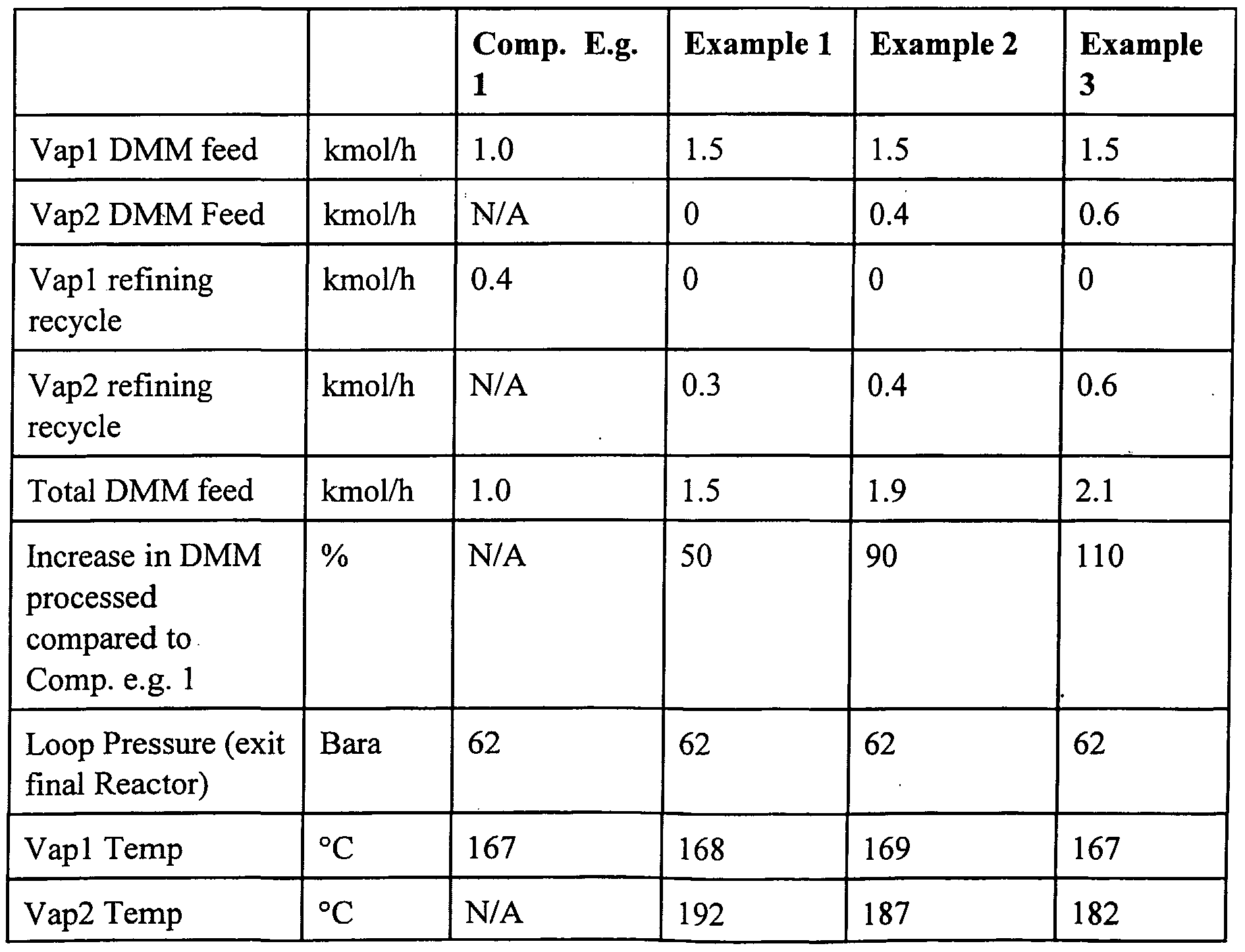
- the compressor cycle gas stream is maintained at the same absolute rate as that for Comparative Example 1.
- 1.5 kmol/h of dimethyl maleate is fed to the first vaporiser.
- No feed dimethyl maleate is fed to the second vaporiser.
- 0.3 kmol h of refining recycle is fed to the second vaporiser.
- 311 kmol/h of hydrogen cycle gas and 7.6 kmol/h of make up hydrogen are fed to the first vaporiser to vaporise the dimethyl maleate feed and the vaporised stream passes to the first reactor where conversion to crude product occurs.
- the reactor contains a sufficient quantity of suitable catalyst to convert approximately 50% of the dimethyl maleate to tetrahydrofuran.
- the stream from this reactor passes to the second vaporiser where it is used to vaporise refining recycle.
- the stream from the second vaporiser passes to the second reactor where conversion to crude product occurs.
- the products from the second reactor are refined and the refining recycles separated and recycled to the second vaporiser.
- the selectivity to tetrahydrofuran is measured.
- the reaction details and results are set out in Table 1. It can be seen that approximately 50% more dimethyl maleate is reacted than is possible with the procedure of the prior art.
- the compressor cycle gas stream is maintained at the same absolute rate as that for Comparative Example 1.
- a total dimethyl maleate feed of 1.9 kmol/h is fed to the system with 1.5 kmol/h being provided to the first vaporiser and 0.4 kmol/h to the second vaporiser.
- 311 kmol/h of hydrogen cycle gas and 9.4 kmol/h of make up hydrogen are fed to the first vaporiser to vaporise the dimethyl maleate feed before the vaporised stream is passed to the first reactor where conversion to crude product occurs.
- the reactor contains a sufficient quantity of suitable catalyst to convert approximately 50% of the dimethyl maleate to tetrahydrofuran.
- the stream from this reactor passes to the second vaporiser where it is used to vaporise refining recycle.
- the stream from the second vaporiser passes to the second reactor where conversion to crude product occurs.
- the products from the second reactor are refined and the refining recycles separated and recycled to the second vaporiser.
- the selectivity to tetrahydrofuran is measured.
- the reaction details and results are set out in Table 1. It can be seen that approximately 90% more dimethyl maleate is reacted than is possible with the procedure ofthe prior art.
- the compressor cycle gas stream is maintained at the same absolute rate as that for Comparative Example 1.
- 1.5 kmol/h of dimethyl maleate is fed to the first vaporiser.
- No feed dimethyl maleate is fed to the second vaporiser.
- 0.75 kmol/h of refining recycle is fed to the second vaporiser 27.
- 311 kmol/h of hydrogen cycle gas and 7.6 kmol/h of make up hydrogen are fed to the first vaporiser to vaporise the dimethyl maleate feed before the vaporised stream passes to the first reactor where conversion to crude product occurs.
- the reactor contains a sufficient quantity of suitable catalyst to convert approximately 50% of the dimethyl maleate to tetrahydrofuran.
- the stream from this reactor passes to the second vaporiser where it is used to vaporise refining recycle.
- the stream from the second vaporiser passes to the second reactor where conversion to crude product occurs.
- the products from the second reactor are refined and the refining recycles separated and recycled to the second vaporiser.
- the selectivity to tetrahydrofuran is measured.
- the reaction details and results are set out in Table 1. It can be seen that approximately 110% more dimethyl maleate is reacted than is possible with the procedure ofthe prior art.
- Vapl and Vap2 are the first and second vaporisers respectively.
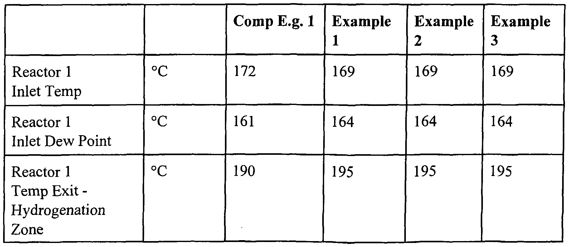
- the dew points at various points in the first reaction zone are determined and compared.
- the results are set out in Table 2. These results assume that the hydrogenation reaction is 100%) and is followed by dehydration. In reality it will be understood that some, i.e. less than 10 mol%> dehydration may occur in the hydrogenation zone and that there will be some hydrogenation of residual ester and/or lactone in the dehydration zone. It is also necessary to note that the system is non-ideal and that it is necessary to allow for vapour pressure errors and heat of reaction errors.
- Examples 1 to 3 have a significantly larger dew point margin exit for the first reactor than for the comparative example.
- This increase in dew point margin occurs primarily as a result of the dehydration of the butane- 1,4-diol to the tetrahydrofuran that has taken place within the first reactor. It will be noted that the wider the dew point margin exit from the first reactor, the more feed material can be vaporised in the downstream vaporiser with a corresponding increase in hydrogenation loop productivity and reduction in the cycle gas flow per unit of dimethylmaleate feed.
Abstract
Description


Claims
Priority Applications (13)
| Application Number | Priority Date | Filing Date | Title |
|---|---|---|---|
| DE60204464T DE60204464T2 (en) | 2001-07-12 | 2002-07-10 | PROCESS FOR THE PRODUCTION OF ETHERS, PREFERABLY THF |
| CA2451595A CA2451595C (en) | 2001-07-12 | 2002-07-10 | Process for the production of ethers, typically thf |
| AT02740957T ATE296816T1 (en) | 2001-07-12 | 2002-07-10 | METHOD FOR PRODUCING ETHERS, PREFERABLY THF |
| EA200400173A EA005339B1 (en) | 2001-07-12 | 2002-07-10 | Process for the production of ethers typically tetrahydrofuran |
| MXPA03010841 MX234385B (en) | 2001-07-12 | 2002-07-10 | Process for the production of ethers, typically thf. |
| EP02740957A EP1404660B1 (en) | 2001-07-12 | 2002-07-10 | Process for the production of ethers, typically thf |
| US10/483,524 US6936727B2 (en) | 2001-07-12 | 2002-07-10 | Process for the production of ethers, typically thf |
| JP2003512218A JP4391816B2 (en) | 2001-07-12 | 2002-07-10 | Method for producing ether, typically THF |
| AU2002314385A AU2002314385B2 (en) | 2001-07-12 | 2002-07-10 | Process for the production of ethers, typically THF |
| KR20037011701A KR100607120B1 (en) | 2001-07-12 | 2002-07-10 | Process for the production of ethers, typically THF |
| BRPI0211085-7A BR0211085B1 (en) | 2001-07-12 | 2002-07-10 | process for the production of ethers, typically thf. |
| ZA2003/09001A ZA200309001B (en) | 2001-07-12 | 2003-11-19 | Process for the production of ethers typically thf |
| NO20040081A NO328297B1 (en) | 2001-07-12 | 2004-01-08 | Process for the preparation of ethers, typically THF |
Applications Claiming Priority (2)
| Application Number | Priority Date | Filing Date | Title |
|---|---|---|---|
| GBGB0117090.1A GB0117090D0 (en) | 2001-07-12 | 2001-07-12 | Process |
| GB0117090.1 | 2001-07-12 |
Publications (2)
| Publication Number | Publication Date |
|---|---|
| WO2003006446A1 true WO2003006446A1 (en) | 2003-01-23 |
| WO2003006446A8 WO2003006446A8 (en) | 2003-08-14 |
Family
ID=9918421
Family Applications (1)
| Application Number | Title | Priority Date | Filing Date |
|---|---|---|---|
| PCT/GB2002/003195 WO2003006446A1 (en) | 2001-07-12 | 2002-07-10 | Process for the production of ethers, typically thf |
Country Status (20)
| Country | Link |
|---|---|
| US (1) | US6936727B2 (en) |
| EP (1) | EP1404660B1 (en) |
| JP (1) | JP4391816B2 (en) |
| KR (1) | KR100607120B1 (en) |
| CN (1) | CN1309714C (en) |
| AR (1) | AR036338A1 (en) |
| AT (1) | ATE296816T1 (en) |
| AU (1) | AU2002314385B2 (en) |
| BR (1) | BR0211085B1 (en) |
| CA (1) | CA2451595C (en) |
| DE (1) | DE60204464T2 (en) |
| EA (1) | EA005339B1 (en) |
| ES (1) | ES2240759T3 (en) |
| GB (1) | GB0117090D0 (en) |
| MX (1) | MX234385B (en) |
| MY (1) | MY129064A (en) |
| NO (1) | NO328297B1 (en) |
| TW (1) | TWI318975B (en) |
| WO (1) | WO2003006446A1 (en) |
| ZA (1) | ZA200309001B (en) |
Cited By (6)
| Publication number | Priority date | Publication date | Assignee | Title |
|---|---|---|---|---|
| JP2007516978A (en) * | 2003-12-16 | 2007-06-28 | デイビー プロセス テクノロジー リミテッド | Method for producing ethers |
| US8129548B2 (en) | 2004-10-01 | 2012-03-06 | Davy Process Technology Limited | Process for the purification of 1,4-butanediol |
| WO2012038242A1 (en) | 2010-09-24 | 2012-03-29 | Basf Se | Process for obtaining tetrahydrofuran |
| US9186599B2 (en) | 2010-09-24 | 2015-11-17 | Basf Se | Process for isolating tetrahydrofuran |
| US9776947B2 (en) | 2013-10-14 | 2017-10-03 | Johnson Matthey Davy Technologies Limited | Process for the production of dialkyl succinate from maleic anyhdride |
| US10308623B2 (en) | 2015-01-09 | 2019-06-04 | Basf Se | Method for producing tetrahydrofurane, 1,4-butanediol or gamma-butyrolactone |
Families Citing this family (6)
| Publication number | Priority date | Publication date | Assignee | Title |
|---|---|---|---|---|
| GB0614823D0 (en) * | 2006-07-26 | 2006-09-06 | Davy Process Techn Ltd | Process |
| WO2008062433A2 (en) * | 2006-08-22 | 2008-05-29 | Dorf Ketal Chemicals (I) Private Limited | Method of removal of calcium from hydrocarbon feedstock |
| MY160536A (en) | 2008-01-24 | 2017-03-15 | Dorf Ketal Chemicals (I) Private Ltd | Method of removing metals from hydrocarbon feedstock using esters of carboxylic acids |
| GB0803663D0 (en) * | 2008-02-28 | 2008-04-09 | Davy Process Techn Ltd | Process |
| IN2014MN01013A (en) | 2011-11-25 | 2015-07-03 | Conser Spa | |
| US20130296585A1 (en) | 2012-03-30 | 2013-11-07 | Basf Corporation | Catalyst For Tetrahydrofuran Synthesis |
Citations (8)
| Publication number | Priority date | Publication date | Assignee | Title |
|---|---|---|---|---|
| GB1226292A (en) * | 1968-01-25 | 1971-03-24 | ||
| WO1986003189A1 (en) * | 1984-11-21 | 1986-06-05 | Davy Mckee (London) Limited | Process for the production of butane-1,4-diol |
| WO1991001981A1 (en) * | 1989-08-04 | 1991-02-21 | Davy Mckee (London) Limited | Process for preparing tetrahydrofuran |
| WO1991001961A1 (en) * | 1989-08-04 | 1991-02-21 | Davy Mckee (London) Limited | Process |
| WO1997043242A1 (en) * | 1996-05-14 | 1997-11-20 | Kvaerner Process Technology Limited | Process for the production of 1,4-butanediol, gamma-butyrolactone and tetrahydrofuran |
| WO1999048852A1 (en) * | 1998-03-23 | 1999-09-30 | Basf Aktiengesellschaft | Process for the preparation of butanediol, butyrolactone and tetrahydrofuran |
| JP2001048819A (en) * | 1999-08-04 | 2001-02-20 | Tonen Chem Corp | Method for hydrogenating dicarboxylic acid compounds at two stages |
| EP1108702A1 (en) * | 1999-12-13 | 2001-06-20 | Kvaerner Process Technology Limited | Process for the co-production of aliphatic diols and cyclic ethers |
Family Cites Families (17)
| Publication number | Priority date | Publication date | Assignee | Title |
|---|---|---|---|---|
| US4451677A (en) | 1981-08-20 | 1984-05-29 | Davy Mckee (London) Limited | Multistage aldehyde hydrogenation |
| JPS60114017A (en) * | 1983-11-26 | 1985-06-20 | Victor Co Of Japan Ltd | Feedback type comb line filter |
| GB8331793D0 (en) | 1983-11-29 | 1984-01-04 | Davy Mckee Ltd | Process |
| US4584491A (en) * | 1984-01-12 | 1986-04-22 | Motorola, Inc. | TTL to CMOS input buffer circuit for minimizing power consumption |
| GB8514002D0 (en) | 1985-06-04 | 1985-07-10 | Davy Mckee Ltd | Process |
| US4626604A (en) | 1985-09-11 | 1986-12-02 | Davy Mckee (London) Limited | Hydrogenation process |
| GB8618890D0 (en) | 1986-08-01 | 1986-09-10 | Davy Mckee Ltd | Process |
| GB8618888D0 (en) | 1986-08-01 | 1986-09-10 | Davy Mckee Ltd | Process |
| WO1988000937A1 (en) | 1986-08-01 | 1988-02-11 | Davy Mckee (London) Limited | Process for the co-production of butane-1,4-diol and gamma-butyrolactone |
| GB8717993D0 (en) | 1987-07-29 | 1987-09-03 | Davy Mckee Ltd | Process |
| GB8717992D0 (en) | 1987-07-29 | 1987-09-03 | Davy Mckee Ltd | Process |
| GB8811009D0 (en) | 1988-05-10 | 1988-06-15 | Bp Chem Int Ltd | Chemical process |
| PH28387A (en) | 1989-01-17 | 1994-08-11 | Davy Process Techn Ltd | Process and apparatus |
| GB8917859D0 (en) | 1989-08-04 | 1989-09-20 | Davy Mckee London | Process |
| US5254318A (en) | 1992-07-20 | 1993-10-19 | Stone & Webster Engineering Corporation | Lined reformer tubes for high pressure reformer reactors |
| GB9324753D0 (en) * | 1993-12-02 | 1994-01-19 | Davy Mckee London | Process |
| ZA973971B (en) | 1996-05-15 | 1998-03-23 | Kvaerner Process Tech Ltd | A process for the production of at least one C4 compound selected from butane-1,4-diol, gamma-butyrolactone and tetrahydrofuran. |
-
2001
- 2001-07-12 GB GBGB0117090.1A patent/GB0117090D0/en not_active Ceased
-
2002
- 2002-07-10 DE DE60204464T patent/DE60204464T2/en not_active Expired - Lifetime
- 2002-07-10 MX MXPA03010841 patent/MX234385B/en active IP Right Grant
- 2002-07-10 EP EP02740957A patent/EP1404660B1/en not_active Expired - Lifetime
- 2002-07-10 AT AT02740957T patent/ATE296816T1/en not_active IP Right Cessation
- 2002-07-10 JP JP2003512218A patent/JP4391816B2/en not_active Expired - Fee Related
- 2002-07-10 ES ES02740957T patent/ES2240759T3/en not_active Expired - Lifetime
- 2002-07-10 CN CNB028111710A patent/CN1309714C/en not_active Expired - Lifetime
- 2002-07-10 KR KR20037011701A patent/KR100607120B1/en active IP Right Grant
- 2002-07-10 WO PCT/GB2002/003195 patent/WO2003006446A1/en active IP Right Grant
- 2002-07-10 AU AU2002314385A patent/AU2002314385B2/en not_active Ceased
- 2002-07-10 CA CA2451595A patent/CA2451595C/en not_active Expired - Fee Related
- 2002-07-10 BR BRPI0211085-7A patent/BR0211085B1/en not_active IP Right Cessation
- 2002-07-10 EA EA200400173A patent/EA005339B1/en not_active IP Right Cessation
- 2002-07-10 US US10/483,524 patent/US6936727B2/en not_active Expired - Lifetime
- 2002-07-11 TW TW091115407A patent/TWI318975B/en not_active IP Right Cessation
- 2002-07-11 MY MYPI20022637A patent/MY129064A/en unknown
- 2002-07-12 AR ARP020102602A patent/AR036338A1/en not_active Application Discontinuation
-
2003
- 2003-11-19 ZA ZA2003/09001A patent/ZA200309001B/en unknown
-
2004
- 2004-01-08 NO NO20040081A patent/NO328297B1/en not_active IP Right Cessation
Patent Citations (8)
| Publication number | Priority date | Publication date | Assignee | Title |
|---|---|---|---|---|
| GB1226292A (en) * | 1968-01-25 | 1971-03-24 | ||
| WO1986003189A1 (en) * | 1984-11-21 | 1986-06-05 | Davy Mckee (London) Limited | Process for the production of butane-1,4-diol |
| WO1991001981A1 (en) * | 1989-08-04 | 1991-02-21 | Davy Mckee (London) Limited | Process for preparing tetrahydrofuran |
| WO1991001961A1 (en) * | 1989-08-04 | 1991-02-21 | Davy Mckee (London) Limited | Process |
| WO1997043242A1 (en) * | 1996-05-14 | 1997-11-20 | Kvaerner Process Technology Limited | Process for the production of 1,4-butanediol, gamma-butyrolactone and tetrahydrofuran |
| WO1999048852A1 (en) * | 1998-03-23 | 1999-09-30 | Basf Aktiengesellschaft | Process for the preparation of butanediol, butyrolactone and tetrahydrofuran |
| JP2001048819A (en) * | 1999-08-04 | 2001-02-20 | Tonen Chem Corp | Method for hydrogenating dicarboxylic acid compounds at two stages |
| EP1108702A1 (en) * | 1999-12-13 | 2001-06-20 | Kvaerner Process Technology Limited | Process for the co-production of aliphatic diols and cyclic ethers |
Non-Patent Citations (1)
| Title |
|---|
| DATABASE WPI Week 200143, Derwent World Patents Index; AN 2001-401000, XP002188766 * |
Cited By (7)
| Publication number | Priority date | Publication date | Assignee | Title |
|---|---|---|---|---|
| JP2007516978A (en) * | 2003-12-16 | 2007-06-28 | デイビー プロセス テクノロジー リミテッド | Method for producing ethers |
| US7598404B2 (en) | 2003-12-16 | 2009-10-06 | Davy Process Technology Limited | Process for the production of ethers |
| US8129548B2 (en) | 2004-10-01 | 2012-03-06 | Davy Process Technology Limited | Process for the purification of 1,4-butanediol |
| WO2012038242A1 (en) | 2010-09-24 | 2012-03-29 | Basf Se | Process for obtaining tetrahydrofuran |
| US9186599B2 (en) | 2010-09-24 | 2015-11-17 | Basf Se | Process for isolating tetrahydrofuran |
| US9776947B2 (en) | 2013-10-14 | 2017-10-03 | Johnson Matthey Davy Technologies Limited | Process for the production of dialkyl succinate from maleic anyhdride |
| US10308623B2 (en) | 2015-01-09 | 2019-06-04 | Basf Se | Method for producing tetrahydrofurane, 1,4-butanediol or gamma-butyrolactone |
Also Published As
| Publication number | Publication date |
|---|---|
| CA2451595A1 (en) | 2003-01-23 |
| DE60204464T2 (en) | 2006-05-11 |
| NO20040081L (en) | 2004-01-08 |
| TWI318975B (en) | 2010-01-01 |
| KR100607120B1 (en) | 2006-08-01 |
| ZA200309001B (en) | 2005-01-26 |
| KR20040022413A (en) | 2004-03-12 |
| EA005339B1 (en) | 2005-02-24 |
| ES2240759T3 (en) | 2005-10-16 |
| CN1309714C (en) | 2007-04-11 |
| GB0117090D0 (en) | 2001-09-05 |
| AU2002314385B2 (en) | 2007-09-20 |
| MX234385B (en) | 2006-02-13 |
| EP1404660B1 (en) | 2005-06-01 |
| NO328297B1 (en) | 2010-01-25 |
| US6936727B2 (en) | 2005-08-30 |
| BR0211085B1 (en) | 2013-05-21 |
| EA200400173A1 (en) | 2004-06-24 |
| MY129064A (en) | 2007-03-30 |
| CN1512989A (en) | 2004-07-14 |
| ATE296816T1 (en) | 2005-06-15 |
| MXPA03010841A (en) | 2004-02-17 |
| CA2451595C (en) | 2011-01-18 |
| JP2005505516A (en) | 2005-02-24 |
| JP4391816B2 (en) | 2009-12-24 |
| AR036338A1 (en) | 2004-09-01 |
| DE60204464D1 (en) | 2005-07-07 |
| US20040199026A1 (en) | 2004-10-07 |
| BR0211085A (en) | 2004-06-15 |
| WO2003006446A8 (en) | 2003-08-14 |
| EP1404660A1 (en) | 2004-04-07 |
Similar Documents
| Publication | Publication Date | Title |
|---|---|---|
| US4751334A (en) | Process for the production of butane-1,4-diol | |
| WO1986003189A1 (en) | Process for the production of butane-1,4-diol | |
| EP1404660B1 (en) | Process for the production of ethers, typically thf | |
| WO2013076747A1 (en) | Process for producing 1,4- butanediol by hydrogenating dialkyl maleate in mixed liquid/vapor phase | |
| WO1986007358A1 (en) | Process for the production of gamma-butyrolactone | |
| AU2002314385A1 (en) | Process for the production of ethers, typically THF | |
| EP1694661B1 (en) | Process for the production of ethers | |
| WO1991001960A1 (en) | Process | |
| AU2009219875B2 (en) | Process |
Legal Events
| Date | Code | Title | Description |
|---|---|---|---|
| AK | Designated states |
Kind code of ref document: A1 Designated state(s): AE AG AL AM AT AU AZ BA BB BG BR BY BZ CA CH CN CO CR CU CZ DE DK DM DZ EC EE ES FI GB GD GE GH GM HR HU ID IL IN IS JP KE KG KP KR KZ LC LK LR LS LT LU LV MA MD MG MK MN MW MX MZ NO NZ OM PH PL PT RO RU SD SE SG SI SK SL TJ TM TN TR TT TZ UA UG US UZ VN YU ZA ZM ZW |
|
| AL | Designated countries for regional patents |
Kind code of ref document: A1 Designated state(s): GH GM KE LS MW MZ SD SL SZ TZ UG ZM ZW AM AZ BY KG KZ MD RU TJ TM AT BE BG CH CY CZ DE DK EE ES FI FR GB GR IE IT LU MC NL PT SE SK TR BF BJ CF CG CI CM GA GN GQ GW ML MR NE SN TD TG |
|
| 121 | Ep: the epo has been informed by wipo that ep was designated in this application | ||
| DFPE | Request for preliminary examination filed prior to expiration of 19th month from priority date (pct application filed before 20040101) | ||
| CFP | Corrected version of a pamphlet front page |
Free format text: UNDER (54) PUBLISHED TITLE REPLACED BY CORRECT TITLE |
|
| WWE | Wipo information: entry into national phase |
Ref document number: 2002314385 Country of ref document: AU |
|
| WWE | Wipo information: entry into national phase |
Ref document number: 2002740957 Country of ref document: EP |
|
| WWE | Wipo information: entry into national phase |
Ref document number: 1404/DELNP/2003 Country of ref document: IN |
|
| WWE | Wipo information: entry into national phase |
Ref document number: 1020037011701 Country of ref document: KR |
|
| WWE | Wipo information: entry into national phase |
Ref document number: 2003/09001 Country of ref document: ZA Ref document number: 200309001 Country of ref document: ZA |
|
| WWE | Wipo information: entry into national phase |
Ref document number: PA/a/2003/010841 Country of ref document: MX |
|
| WWE | Wipo information: entry into national phase |
Ref document number: 028111710 Country of ref document: CN |
|
| WWE | Wipo information: entry into national phase |
Ref document number: 2451595 Country of ref document: CA |
|
| WWE | Wipo information: entry into national phase |
Ref document number: 2003512218 Country of ref document: JP |
|
| WWE | Wipo information: entry into national phase |
Ref document number: 200400173 Country of ref document: EA |
|
| WWP | Wipo information: published in national office |
Ref document number: 1020037011701 Country of ref document: KR |
|
| WWP | Wipo information: published in national office |
Ref document number: 2002740957 Country of ref document: EP |
|
| WWE | Wipo information: entry into national phase |
Ref document number: 10483524 Country of ref document: US |
|
| REG | Reference to national code |
Ref country code: DE Ref legal event code: 8642 |
|
| WWG | Wipo information: grant in national office |
Ref document number: 2002740957 Country of ref document: EP |
|
| WWG | Wipo information: grant in national office |
Ref document number: 1020037011701 Country of ref document: KR |