WO2000016882A1 - Catalytic converter for removing ozone having anodized and washcoat layers - Google Patents
Catalytic converter for removing ozone having anodized and washcoat layers Download PDFInfo
- Publication number
- WO2000016882A1 WO2000016882A1 PCT/US1999/021635 US9921635W WO0016882A1 WO 2000016882 A1 WO2000016882 A1 WO 2000016882A1 US 9921635 W US9921635 W US 9921635W WO 0016882 A1 WO0016882 A1 WO 0016882A1
- Authority
- WO
- WIPO (PCT)
- Prior art keywords
- layer
- anodized
- catalytic converter
- catalyst
- washcoat
- Prior art date
Links
- 230000003197 catalytic effect Effects 0.000 title claims abstract description 63
- CBENFWSGALASAD-UHFFFAOYSA-N Ozone Chemical compound [O-][O+]=O CBENFWSGALASAD-UHFFFAOYSA-N 0.000 title abstract description 27
- 239000003054 catalyst Substances 0.000 claims abstract description 71
- 230000007613 environmental effect Effects 0.000 claims abstract description 9
- 239000010970 precious metal Substances 0.000 claims abstract description 7
- 150000003624 transition metals Chemical class 0.000 claims abstract description 6
- 229910052723 transition metal Inorganic materials 0.000 claims abstract description 5
- 239000010410 layer Substances 0.000 claims description 165
- PNEYBMLMFCGWSK-UHFFFAOYSA-N Alumina Chemical compound [O-2].[O-2].[O-2].[Al+3].[Al+3] PNEYBMLMFCGWSK-UHFFFAOYSA-N 0.000 claims description 13
- VYPSYNLAJGMNEJ-UHFFFAOYSA-N Silicium dioxide Chemical compound O=[Si]=O VYPSYNLAJGMNEJ-UHFFFAOYSA-N 0.000 claims description 12
- 239000011148 porous material Substances 0.000 claims description 7
- TWNQGVIAIRXVLR-UHFFFAOYSA-N oxo(oxoalumanyloxy)alumane Chemical compound O=[Al]O[Al]=O TWNQGVIAIRXVLR-UHFFFAOYSA-N 0.000 claims description 6
- 239000000377 silicon dioxide Substances 0.000 claims description 6
- 239000002344 surface layer Substances 0.000 claims description 6
- 238000011068 loading method Methods 0.000 claims description 4
- BPQQTUXANYXVAA-UHFFFAOYSA-N Orthosilicate Chemical compound [O-][Si]([O-])([O-])[O-] BPQQTUXANYXVAA-UHFFFAOYSA-N 0.000 claims description 3
- 229910052751 metal Inorganic materials 0.000 abstract description 29
- 239000002184 metal Substances 0.000 abstract description 29
- 229910044991 metal oxide Inorganic materials 0.000 abstract description 22
- 150000004706 metal oxides Chemical class 0.000 abstract description 22
- 150000002739 metals Chemical class 0.000 abstract description 11
- 239000002002 slurry Substances 0.000 description 26
- 238000000034 method Methods 0.000 description 19
- KDLHZDBZIXYQEI-UHFFFAOYSA-N Palladium Chemical compound [Pd] KDLHZDBZIXYQEI-UHFFFAOYSA-N 0.000 description 17
- MUBZPKHOEPUJKR-UHFFFAOYSA-N Oxalic acid Chemical compound OC(=O)C(O)=O MUBZPKHOEPUJKR-UHFFFAOYSA-N 0.000 description 15
- PXHVJJICTQNCMI-UHFFFAOYSA-N Nickel Chemical compound [Ni] PXHVJJICTQNCMI-UHFFFAOYSA-N 0.000 description 11
- 238000001354 calcination Methods 0.000 description 11
- 238000012360 testing method Methods 0.000 description 11
- 230000006378 damage Effects 0.000 description 10
- XLYOFNOQVPJJNP-UHFFFAOYSA-N water Substances O XLYOFNOQVPJJNP-UHFFFAOYSA-N 0.000 description 10
- YXFVVABEGXRONW-UHFFFAOYSA-N Toluene Chemical compound CC1=CC=CC=C1 YXFVVABEGXRONW-UHFFFAOYSA-N 0.000 description 9
- 229910052782 aluminium Inorganic materials 0.000 description 9
- XAGFODPZIPBFFR-UHFFFAOYSA-N aluminium Chemical compound [Al] XAGFODPZIPBFFR-UHFFFAOYSA-N 0.000 description 9
- KRKNYBCHXYNGOX-UHFFFAOYSA-N citric acid Chemical compound OC(=O)CC(O)(C(O)=O)CC(O)=O KRKNYBCHXYNGOX-UHFFFAOYSA-N 0.000 description 9
- 125000005375 organosiloxane group Chemical group 0.000 description 9
- 239000003870 refractory metal Substances 0.000 description 9
- 229920005989 resin Polymers 0.000 description 9
- 239000011347 resin Substances 0.000 description 9
- 229910052763 palladium Inorganic materials 0.000 description 8
- 230000008569 process Effects 0.000 description 8
- 239000000243 solution Substances 0.000 description 8
- 239000011230 binding agent Substances 0.000 description 7
- 229910001593 boehmite Inorganic materials 0.000 description 7
- 238000006243 chemical reaction Methods 0.000 description 7
- FAHBNUUHRFUEAI-UHFFFAOYSA-M hydroxidooxidoaluminium Chemical compound O[Al]=O FAHBNUUHRFUEAI-UHFFFAOYSA-M 0.000 description 7
- 238000005470 impregnation Methods 0.000 description 7
- 239000000203 mixture Substances 0.000 description 6
- 229910052759 nickel Inorganic materials 0.000 description 6
- 239000003153 chemical reaction reagent Substances 0.000 description 5
- 230000007797 corrosion Effects 0.000 description 5
- 238000005260 corrosion Methods 0.000 description 5
- 235000006408 oxalic acid Nutrition 0.000 description 5
- BASFCYQUMIYNBI-UHFFFAOYSA-N platinum Chemical compound [Pt] BASFCYQUMIYNBI-UHFFFAOYSA-N 0.000 description 5
- 230000015572 biosynthetic process Effects 0.000 description 4
- 230000000694 effects Effects 0.000 description 4
- 230000003993 interaction Effects 0.000 description 4
- 239000000463 material Substances 0.000 description 4
- 239000002574 poison Substances 0.000 description 4
- 231100000614 poison Toxicity 0.000 description 4
- 229920002050 silicone resin Polymers 0.000 description 4
- 230000004580 weight loss Effects 0.000 description 4
- QTBSBXVTEAMEQO-UHFFFAOYSA-N Acetic acid Chemical compound CC(O)=O QTBSBXVTEAMEQO-UHFFFAOYSA-N 0.000 description 3
- LFQSCWFLJHTTHZ-UHFFFAOYSA-N Ethanol Chemical compound CCO LFQSCWFLJHTTHZ-UHFFFAOYSA-N 0.000 description 3
- XEEYBQQBJWHFJM-UHFFFAOYSA-N Iron Chemical compound [Fe] XEEYBQQBJWHFJM-UHFFFAOYSA-N 0.000 description 3
- OKKJLVBELUTLKV-UHFFFAOYSA-N Methanol Chemical compound OC OKKJLVBELUTLKV-UHFFFAOYSA-N 0.000 description 3
- RTAQQCXQSZGOHL-UHFFFAOYSA-N Titanium Chemical compound [Ti] RTAQQCXQSZGOHL-UHFFFAOYSA-N 0.000 description 3
- 238000004998 X ray absorption near edge structure spectroscopy Methods 0.000 description 3
- 238000002048 anodisation reaction Methods 0.000 description 3
- 239000011248 coating agent Substances 0.000 description 3
- 238000000576 coating method Methods 0.000 description 3
- 238000010276 construction Methods 0.000 description 3
- 239000010949 copper Substances 0.000 description 3
- 238000004132 cross linking Methods 0.000 description 3
- 238000001723 curing Methods 0.000 description 3
- 238000007598 dipping method Methods 0.000 description 3
- 239000006185 dispersion Substances 0.000 description 3
- 238000009826 distribution Methods 0.000 description 3
- 238000001035 drying Methods 0.000 description 3
- 239000007789 gas Substances 0.000 description 3
- 239000010931 gold Substances 0.000 description 3
- 239000003960 organic solvent Substances 0.000 description 3
- 239000002243 precursor Substances 0.000 description 3
- 239000010948 rhodium Substances 0.000 description 3
- 238000001350 scanning transmission electron microscopy Methods 0.000 description 3
- 239000010935 stainless steel Substances 0.000 description 3
- 229910001220 stainless steel Inorganic materials 0.000 description 3
- 239000000126 substance Substances 0.000 description 3
- 239000000758 substrate Substances 0.000 description 3
- 239000010936 titanium Substances 0.000 description 3
- 238000012546 transfer Methods 0.000 description 3
- 229910000838 Al alloy Inorganic materials 0.000 description 2
- RYGMFSIKBFXOCR-UHFFFAOYSA-N Copper Chemical compound [Cu] RYGMFSIKBFXOCR-UHFFFAOYSA-N 0.000 description 2
- CPLXHLVBOLITMK-UHFFFAOYSA-N Magnesium oxide Chemical compound [Mg]=O CPLXHLVBOLITMK-UHFFFAOYSA-N 0.000 description 2
- OFOBLEOULBTSOW-UHFFFAOYSA-N Malonic acid Chemical compound OC(=O)CC(O)=O OFOBLEOULBTSOW-UHFFFAOYSA-N 0.000 description 2
- 229910002651 NO3 Inorganic materials 0.000 description 2
- NHNBFGGVMKEFGY-UHFFFAOYSA-N Nitrate Chemical compound [O-][N+]([O-])=O NHNBFGGVMKEFGY-UHFFFAOYSA-N 0.000 description 2
- NBIIXXVUZAFLBC-UHFFFAOYSA-N Phosphoric acid Chemical compound OP(O)(O)=O NBIIXXVUZAFLBC-UHFFFAOYSA-N 0.000 description 2
- BQCADISMDOOEFD-UHFFFAOYSA-N Silver Chemical compound [Ag] BQCADISMDOOEFD-UHFFFAOYSA-N 0.000 description 2
- QAOWNCQODCNURD-UHFFFAOYSA-N Sulfuric acid Chemical compound OS(O)(=O)=O QAOWNCQODCNURD-UHFFFAOYSA-N 0.000 description 2
- GWEVSGVZZGPLCZ-UHFFFAOYSA-N Titan oxide Chemical compound O=[Ti]=O GWEVSGVZZGPLCZ-UHFFFAOYSA-N 0.000 description 2
- MCMNRKCIXSYSNV-UHFFFAOYSA-N Zirconium dioxide Chemical compound O=[Zr]=O MCMNRKCIXSYSNV-UHFFFAOYSA-N 0.000 description 2
- 238000004378 air conditioning Methods 0.000 description 2
- AZDRQVAHHNSJOQ-UHFFFAOYSA-N alumane Chemical group [AlH3] AZDRQVAHHNSJOQ-UHFFFAOYSA-N 0.000 description 2
- 230000004888 barrier function Effects 0.000 description 2
- 230000008901 benefit Effects 0.000 description 2
- 238000003421 catalytic decomposition reaction Methods 0.000 description 2
- 238000010382 chemical cross-linking Methods 0.000 description 2
- 229910017052 cobalt Inorganic materials 0.000 description 2
- 239000010941 cobalt Substances 0.000 description 2
- GUTLYIVDDKVIGB-UHFFFAOYSA-N cobalt atom Chemical compound [Co] GUTLYIVDDKVIGB-UHFFFAOYSA-N 0.000 description 2
- 230000001143 conditioned effect Effects 0.000 description 2
- 238000001816 cooling Methods 0.000 description 2
- 229910052802 copper Inorganic materials 0.000 description 2
- PCHJSUWPFVWCPO-UHFFFAOYSA-N gold Chemical compound [Au] PCHJSUWPFVWCPO-UHFFFAOYSA-N 0.000 description 2
- 229910052737 gold Inorganic materials 0.000 description 2
- AMWRITDGCCNYAT-UHFFFAOYSA-L hydroxy(oxo)manganese;manganese Chemical compound [Mn].O[Mn]=O.O[Mn]=O AMWRITDGCCNYAT-UHFFFAOYSA-L 0.000 description 2
- 239000004615 ingredient Substances 0.000 description 2
- 229910052741 iridium Inorganic materials 0.000 description 2
- GKOZUEZYRPOHIO-UHFFFAOYSA-N iridium atom Chemical compound [Ir] GKOZUEZYRPOHIO-UHFFFAOYSA-N 0.000 description 2
- 238000012423 maintenance Methods 0.000 description 2
- 239000011572 manganese Substances 0.000 description 2
- -1 methylphenylsiloxane Chemical class 0.000 description 2
- 150000007524 organic acids Chemical class 0.000 description 2
- 230000003647 oxidation Effects 0.000 description 2
- 238000007254 oxidation reaction Methods 0.000 description 2
- 230000001590 oxidative effect Effects 0.000 description 2
- 239000002245 particle Substances 0.000 description 2
- 229910052697 platinum Inorganic materials 0.000 description 2
- 229910052703 rhodium Inorganic materials 0.000 description 2
- MHOVAHRLVXNVSD-UHFFFAOYSA-N rhodium atom Chemical compound [Rh] MHOVAHRLVXNVSD-UHFFFAOYSA-N 0.000 description 2
- RMAQACBXLXPBSY-UHFFFAOYSA-N silicic acid Chemical compound O[Si](O)(O)O RMAQACBXLXPBSY-UHFFFAOYSA-N 0.000 description 2
- 229910052709 silver Inorganic materials 0.000 description 2
- 239000004332 silver Substances 0.000 description 2
- 239000002904 solvent Substances 0.000 description 2
- 238000001179 sorption measurement Methods 0.000 description 2
- 150000003464 sulfur compounds Chemical class 0.000 description 2
- 230000008646 thermal stress Effects 0.000 description 2
- 229910052719 titanium Inorganic materials 0.000 description 2
- FEWJPZIEWOKRBE-JCYAYHJZSA-N Dextrotartaric acid Chemical compound OC(=O)[C@H](O)[C@@H](O)C(O)=O FEWJPZIEWOKRBE-JCYAYHJZSA-N 0.000 description 1
- 229910001200 Ferrotitanium Inorganic materials 0.000 description 1
- PWHULOQIROXLJO-UHFFFAOYSA-N Manganese Chemical compound [Mn] PWHULOQIROXLJO-UHFFFAOYSA-N 0.000 description 1
- 229910000990 Ni alloy Inorganic materials 0.000 description 1
- CTQNGGLPUBDAKN-UHFFFAOYSA-N O-Xylene Chemical compound CC1=CC=CC=C1C CTQNGGLPUBDAKN-UHFFFAOYSA-N 0.000 description 1
- 229910052581 Si3N4 Inorganic materials 0.000 description 1
- FEWJPZIEWOKRBE-UHFFFAOYSA-N Tartaric acid Natural products [H+].[H+].[O-]C(=O)C(O)C(O)C([O-])=O FEWJPZIEWOKRBE-UHFFFAOYSA-N 0.000 description 1
- 238000002441 X-ray diffraction Methods 0.000 description 1
- YKTSYUJCYHOUJP-UHFFFAOYSA-N [O--].[Al+3].[Al+3].[O-][Si]([O-])([O-])[O-] Chemical compound [O--].[Al+3].[Al+3].[O-][Si]([O-])([O-])[O-] YKTSYUJCYHOUJP-UHFFFAOYSA-N 0.000 description 1
- 210000001015 abdomen Anatomy 0.000 description 1
- 238000010521 absorption reaction Methods 0.000 description 1
- 239000002253 acid Substances 0.000 description 1
- 150000007513 acids Chemical class 0.000 description 1
- 229910045601 alloy Inorganic materials 0.000 description 1
- 239000000956 alloy Substances 0.000 description 1
- 229910000147 aluminium phosphate Inorganic materials 0.000 description 1
- 239000003849 aromatic solvent Substances 0.000 description 1
- 230000009286 beneficial effect Effects 0.000 description 1
- 239000012018 catalyst precursor Substances 0.000 description 1
- 239000000919 ceramic Substances 0.000 description 1
- CETPSERCERDGAM-UHFFFAOYSA-N ceric oxide Chemical compound O=[Ce]=O CETPSERCERDGAM-UHFFFAOYSA-N 0.000 description 1
- 229910000422 cerium(IV) oxide Inorganic materials 0.000 description 1
- KRVSOGSZCMJSLX-UHFFFAOYSA-L chromic acid Substances O[Cr](O)(=O)=O KRVSOGSZCMJSLX-UHFFFAOYSA-L 0.000 description 1
- 239000002131 composite material Substances 0.000 description 1
- 230000003750 conditioning effect Effects 0.000 description 1
- 239000000356 contaminant Substances 0.000 description 1
- 229910052878 cordierite Inorganic materials 0.000 description 1
- 239000008367 deionised water Substances 0.000 description 1
- 229910021641 deionized water Inorganic materials 0.000 description 1
- 238000013461 design Methods 0.000 description 1
- 239000003599 detergent Substances 0.000 description 1
- JSKIRARMQDRGJZ-UHFFFAOYSA-N dimagnesium dioxido-bis[(1-oxido-3-oxo-2,4,6,8,9-pentaoxa-1,3-disila-5,7-dialuminabicyclo[3.3.1]nonan-7-yl)oxy]silane Chemical compound [Mg++].[Mg++].[O-][Si]([O-])(O[Al]1O[Al]2O[Si](=O)O[Si]([O-])(O1)O2)O[Al]1O[Al]2O[Si](=O)O[Si]([O-])(O1)O2 JSKIRARMQDRGJZ-UHFFFAOYSA-N 0.000 description 1
- 239000000428 dust Substances 0.000 description 1
- 238000006056 electrooxidation reaction Methods 0.000 description 1
- AWJWCTOOIBYHON-UHFFFAOYSA-N furo[3,4-b]pyrazine-5,7-dione Chemical compound C1=CN=C2C(=O)OC(=O)C2=N1 AWJWCTOOIBYHON-UHFFFAOYSA-N 0.000 description 1
- 238000010438 heat treatment Methods 0.000 description 1
- 238000003384 imaging method Methods 0.000 description 1
- 229910001026 inconel Inorganic materials 0.000 description 1
- 229910052742 iron Inorganic materials 0.000 description 1
- 125000001449 isopropyl group Chemical group [H]C([H])([H])C([H])(*)C([H])([H])[H] 0.000 description 1
- 239000000314 lubricant Substances 0.000 description 1
- 239000000395 magnesium oxide Substances 0.000 description 1
- 239000002075 main ingredient Substances 0.000 description 1
- 229910052748 manganese Inorganic materials 0.000 description 1
- WPBNNNQJVZRUHP-UHFFFAOYSA-L manganese(2+);methyl n-[[2-(methoxycarbonylcarbamothioylamino)phenyl]carbamothioyl]carbamate;n-[2-(sulfidocarbothioylamino)ethyl]carbamodithioate Chemical compound [Mn+2].[S-]C(=S)NCCNC([S-])=S.COC(=O)NC(=S)NC1=CC=CC=C1NC(=S)NC(=O)OC WPBNNNQJVZRUHP-UHFFFAOYSA-L 0.000 description 1
- 238000004519 manufacturing process Methods 0.000 description 1
- 238000005259 measurement Methods 0.000 description 1
- 150000002823 nitrates Chemical class 0.000 description 1
- 239000003921 oil Substances 0.000 description 1
- 239000011368 organic material Substances 0.000 description 1
- 125000004430 oxygen atom Chemical group O* 0.000 description 1
- 230000003071 parasitic effect Effects 0.000 description 1
- 238000002360 preparation method Methods 0.000 description 1
- 230000001737 promoting effect Effects 0.000 description 1
- 238000005096 rolling process Methods 0.000 description 1
- 239000012266 salt solution Substances 0.000 description 1
- 230000035939 shock Effects 0.000 description 1
- HQVNEWCFYHHQES-UHFFFAOYSA-N silicon nitride Chemical compound N12[Si]34N5[Si]62N3[Si]51N64 HQVNEWCFYHHQES-UHFFFAOYSA-N 0.000 description 1
- 238000004611 spectroscopical analysis Methods 0.000 description 1
- 230000035882 stress Effects 0.000 description 1
- 230000002195 synergetic effect Effects 0.000 description 1
- 239000011975 tartaric acid Substances 0.000 description 1
- 235000002906 tartaric acid Nutrition 0.000 description 1
- 238000010998 test method Methods 0.000 description 1
- 238000005382 thermal cycling Methods 0.000 description 1
- 231100000331 toxic Toxicity 0.000 description 1
- 230000002588 toxic effect Effects 0.000 description 1
- 230000007704 transition Effects 0.000 description 1
- 238000011144 upstream manufacturing Methods 0.000 description 1
- 239000008096 xylene Substances 0.000 description 1
- 150000003752 zinc compounds Chemical class 0.000 description 1
- CHJMFFKHPHCQIJ-UHFFFAOYSA-L zinc;octanoate Chemical compound [Zn+2].CCCCCCCC([O-])=O.CCCCCCCC([O-])=O CHJMFFKHPHCQIJ-UHFFFAOYSA-L 0.000 description 1
Classifications
-
- B—PERFORMING OPERATIONS; TRANSPORTING
- B64—AIRCRAFT; AVIATION; COSMONAUTICS
- B64D—EQUIPMENT FOR FITTING IN OR TO AIRCRAFT; FLIGHT SUITS; PARACHUTES; ARRANGEMENTS OR MOUNTING OF POWER PLANTS OR PROPULSION TRANSMISSIONS IN AIRCRAFT
- B64D13/00—Arrangements or adaptations of air-treatment apparatus for aircraft crew or passengers, or freight space, or structural parts of the aircraft
- B64D13/06—Arrangements or adaptations of air-treatment apparatus for aircraft crew or passengers, or freight space, or structural parts of the aircraft the air being conditioned
-
- B—PERFORMING OPERATIONS; TRANSPORTING
- B01—PHYSICAL OR CHEMICAL PROCESSES OR APPARATUS IN GENERAL
- B01D—SEPARATION
- B01D53/00—Separation of gases or vapours; Recovering vapours of volatile solvents from gases; Chemical or biological purification of waste gases, e.g. engine exhaust gases, smoke, fumes, flue gases, aerosols
- B01D53/34—Chemical or biological purification of waste gases
- B01D53/74—General processes for purification of waste gases; Apparatus or devices specially adapted therefor
- B01D53/86—Catalytic processes
- B01D53/8671—Removing components of defined structure not provided for in B01D53/8603 - B01D53/8668
- B01D53/8675—Ozone
-
- B—PERFORMING OPERATIONS; TRANSPORTING
- B01—PHYSICAL OR CHEMICAL PROCESSES OR APPARATUS IN GENERAL
- B01J—CHEMICAL OR PHYSICAL PROCESSES, e.g. CATALYSIS OR COLLOID CHEMISTRY; THEIR RELEVANT APPARATUS
- B01J21/00—Catalysts comprising the elements, oxides, or hydroxides of magnesium, boron, aluminium, carbon, silicon, titanium, zirconium, or hafnium
-
- B—PERFORMING OPERATIONS; TRANSPORTING
- B01—PHYSICAL OR CHEMICAL PROCESSES OR APPARATUS IN GENERAL
- B01J—CHEMICAL OR PHYSICAL PROCESSES, e.g. CATALYSIS OR COLLOID CHEMISTRY; THEIR RELEVANT APPARATUS
- B01J23/00—Catalysts comprising metals or metal oxides or hydroxides, not provided for in group B01J21/00
- B01J23/70—Catalysts comprising metals or metal oxides or hydroxides, not provided for in group B01J21/00 of the iron group metals or copper
- B01J23/89—Catalysts comprising metals or metal oxides or hydroxides, not provided for in group B01J21/00 of the iron group metals or copper combined with noble metals
- B01J23/892—Nickel and noble metals
-
- B—PERFORMING OPERATIONS; TRANSPORTING
- B01—PHYSICAL OR CHEMICAL PROCESSES OR APPARATUS IN GENERAL
- B01J—CHEMICAL OR PHYSICAL PROCESSES, e.g. CATALYSIS OR COLLOID CHEMISTRY; THEIR RELEVANT APPARATUS
- B01J37/00—Processes, in general, for preparing catalysts; Processes, in general, for activation of catalysts
- B01J37/02—Impregnation, coating or precipitation
- B01J37/0215—Coating
- B01J37/0225—Coating of metal substrates
- B01J37/0226—Oxidation of the substrate, e.g. anodisation
-
- B—PERFORMING OPERATIONS; TRANSPORTING
- B01—PHYSICAL OR CHEMICAL PROCESSES OR APPARATUS IN GENERAL
- B01J—CHEMICAL OR PHYSICAL PROCESSES, e.g. CATALYSIS OR COLLOID CHEMISTRY; THEIR RELEVANT APPARATUS
- B01J37/00—Processes, in general, for preparing catalysts; Processes, in general, for activation of catalysts
- B01J37/02—Impregnation, coating or precipitation
- B01J37/024—Multiple impregnation or coating
- B01J37/0244—Coatings comprising several layers
-
- B—PERFORMING OPERATIONS; TRANSPORTING
- B01—PHYSICAL OR CHEMICAL PROCESSES OR APPARATUS IN GENERAL
- B01D—SEPARATION
- B01D2255/00—Catalysts
- B01D2255/10—Noble metals or compounds thereof
- B01D2255/102—Platinum group metals
- B01D2255/1021—Platinum
-
- B—PERFORMING OPERATIONS; TRANSPORTING
- B01—PHYSICAL OR CHEMICAL PROCESSES OR APPARATUS IN GENERAL
- B01D—SEPARATION
- B01D2255/00—Catalysts
- B01D2255/20—Metals or compounds thereof
- B01D2255/207—Transition metals
- B01D2255/20746—Cobalt
-
- B—PERFORMING OPERATIONS; TRANSPORTING
- B64—AIRCRAFT; AVIATION; COSMONAUTICS
- B64D—EQUIPMENT FOR FITTING IN OR TO AIRCRAFT; FLIGHT SUITS; PARACHUTES; ARRANGEMENTS OR MOUNTING OF POWER PLANTS OR PROPULSION TRANSMISSIONS IN AIRCRAFT
- B64D13/00—Arrangements or adaptations of air-treatment apparatus for aircraft crew or passengers, or freight space, or structural parts of the aircraft
- B64D13/06—Arrangements or adaptations of air-treatment apparatus for aircraft crew or passengers, or freight space, or structural parts of the aircraft the air being conditioned
- B64D2013/0603—Environmental Control Systems
- B64D2013/0685—Environmental Control Systems with ozone control
Definitions
- the present invention relates to environmental control systems. More specifically, the present invention relates to an environmental control system including an ozone-destroying catalytic converter.
- a commercial aircraft usually includes an environmental control system for providing a stream of cooled, conditioned air to an aircraft cabin.
- a typical environmental control system receives compressed air such as bleed air from a compressor stage of an aircraft gas turbine engine, expands the compressed air in a cooling turbine and removes moisture from the compressed air via a water extractor.
- Toxic ozone in the compressed air becomes an issue when an aircraft is cruising at altitudes that exceed 20,000 feet.
- the environmental system is provided with an ozone-destroying catalytic converter.
- ozone- destroying catalytic converter of an aircraft There are a number of desirable characteristics for an ozone- destroying catalytic converter of an aircraft. These characteristics include a) high efficiency of ozone conversion at bleed air operating temperature; b) good poison resistance from humidity, sulfur compounds, oil, dust, and the like, which may be present in the compressed air (for long life and minimum system overhaul and maintenance costs); c) light weight to minimize system parasitic load; d) high structural integrity of catalyst support under extreme heat and/or vibration shock, which may arise during normal flight conditions (also for long life and minimum system overhaul and maintenance costs); and e) high mass transport efficiency with low pressure drop.
- An ozone-destroying catalytic converter with a metal core may be washcoated with a slurry of a water-based silica sol and a refractory metal to form an undercoat layer followed by an overcoat layer of alumina oxide. Both layers may then be catalyzed directly by dipping the washcoated core in a catalyst solution having strong acidity. However, the strongly acidity can cause corrosion of the metal core, especially if the core is made of aluminum.
- the overcoat layer may be pre-catalyzed and then washcoated onto the core. Using a pre-catalyzed layer can prevent corrosion during the catalyzing process.
- Applying the pre-catalyzed overcoat layer can be problematic. For example, it is difficult to control the uniformity of washcoat layer thickness. Unevenness of the layer thickness can cause a pressure drop across the catalytic converter.
- Another problem with the pre-catalyzed overcoat layer is poor catalyst utilization efficiency. Washcoating the pre-catalyzed metal oxide can render certain fractions of the catalytic site inaccessible due to the shielding of the binder material. Furthermore, the surface area provided by the undercoat is not utilized to extend the catalyst lifetime. Since poisons in the compressed air can reduce the efficiency of conversion, lifetime and efficiency of the catalytic converter is further reduced because of the poor catalyst utilization efficiency.
- a catalytic converter for a commercial aircraft is subjected to high temperatures and large temperature swings (e.g., between 150 °F and 500°F) during normal flight operation.
- the catalytic converter is also subjected to high vibrations during normal flight operation. These harsh conditions can cause the washcoat layer to fiake off. Consequently, operating life of the catalytic converter is reduced.
- an ozone- destroying catalytic converter comprises a core; an anodized surface layer formed from a portion of the core; a washcoat layer on the anodized layer; and an ozone-destroying catalyst impregnated in the washcoat layer.
- the combination of the anodized and washcoat layers offers many advantages.
- the anodized layer provides a support for the catalyst and a corrosion barrier that prevents a catalyzing reagent from attacking the core during catalyst impregnation. Therefore, the catalyst can be impregnated after formation of the washcoat layer to provide maximum catalyst utilization and lifetime.
- the anodized layer significantly improves the binding strength between the core and the washcoat layer, which allows the washcoat layer to withstand high temperatures, large temperature swings and high vibrations such as those occurring during normal aircraft flight conditions.
- the anodized layer also provides additional surface area and, therefore, increases the efficiency of ozone conversion and mass transport.
- the washcoat layer may be formed by creating a slurry including a refractory metal oxide and an organosiloxane resin in monomeric or polymeric form.
- the refractory metal oxide may be partially hydrated.
- the core is dipped in the slurry and the resulting washcoat is dried.
- Such a slurry dries faster than slurries that include water-based binders.
- the faster drying allows the washcoat layer to be applied more uniformly than a washcoat layer formed from a slurry that includes a water-based binder.
- the dried washcoat is then cured and calcined.
- washcoat layer is applied to an anodized layer of the core, cross-linking of the chemical bonds between metal oxide particles, anodized surface and organosiloxane resin occurs during the curing and calcination.
- This cross- linking results in a washcoat layer having significant mechanical and thermal strength. Consequently, the washcoat layer is free from flaking.
- Figure 1 is an illustration of an environmental control system including an ozone-destroying catalytic converter according to the present invention
- Figure 2 is an illustration of a cross-section of a surface of a core of the ozone-destroying catalytic converter, an anodized surface layer formed from the core, a washcoat layer on the anodized layer, and an ozone-destroying catalyst impregnated in the anodized and washcoat layers;
- Figure 3 is a perspective view of a portion of a plate-fin element for an ozone-destroying catalytic converter
- Figure 4 is an illustration of a method of preparing a core of the catalytic converter.
- FIG. 1 shows an aircraft environmental control system (“ECS”) 10 for an aircraft.
- the ECS 10 receives compressed air such as bleed air from a compressor section of the aircraft's main engine.
- the ECS 10 includes at least one air-to-air heat exchanger (“HX”) 12 for cooling the compressed air to near-ambient temperature; and an air conditioning system (“ACS”) 14 for conditioning the air that was cooled in the air-to-air heat exchanger 12.
- the air conditioning system 14 may include an air cycle machine and a water extractor for expanding the air and reducing moisture in the air.
- the ECS 10 supplies cooled, conditioned air to a cabin 16 or other compartment of the aircraft.
- the ECS 10 also includes a catalytic converter 18, which may be located in the belly of the aircraft, between the source of the compressed air and the air-to-air heat exchanger 12.
- the catalytic converter 18 is mounted inside a shell 20 through which the compressed air flows. The compressed air passes through the catalytic converter 18, which destroys ozone in the compressed air.
- a precooler may be located upstream the catalytic converter 18.
- the pre-cooler lowers the temperature of the compressed air prior to ozone destruction.
- FIG. 2 illustrates a cross-section of a surface of a portion of the catalytic converter 18.
- the catalytic converter includes a core 22, an anodized surface layer 24 formed from a portion of the core 22, a washcoat layer 26 formed on the anodized layer 24, and an ozone- destroying catalyst 28 impregnated in both the washcoat layer 26 and the anodized layer 24 (the layers 24 and 26 and the catalyst 28 are not shown to scale).
- the anodized layer 24 has a thickness between about five to ten microns.
- the anodized layer 24 is dense at the interface with the core 22.
- the anodized layer 24 has a rough surface at the interface with the washcoat layer 26.
- the anodized layer 24 may have a preferred surface area ranging from 5 to 15 m 2 /gram, including the weight of the fins. Since the anodized layer 24 is integral with the core 22, it is difficult to accurately determine the surface area of the anodized layer 24 excluding the core 22.
- the washcoat layer 26 is highly porous, having a preferred pore volume ranging from 0.2 to 0.9 cm 3 /gram, and an average pore size ranging from 3 to 25 nm.
- the washcoat layer 26 has a large surface area.
- the washcoat layer 26 has a preferred surface area ranging from 50 to 70 m 2 /gram including the weight of the fins, and a surface area ranging from 200 to 350 m 2 /gram excluding the weight of the fins.
- the washcoat layer has adjustable thickness between about five to sixty microns.
- the catalyst 28 is impregnated into both the washcoat layer 26 and the anodized layer 24.
- Concentration of the catalyst 28 in the washcoat layer 26 may be higher than concentration of the catalyst 28 in the anodized layer 24.
- the catalyst concentration in the washcoat layer 26 may be two to four times the catalyst concentration in the anodized layer 24.
- the catalyst 28 may be monometallic, or it may be bimetallic in the form of oxide with different valence states or in zero valance metallic state.
- a precious metal such as palladium (Pd)
- Pd palladium
- a bimetallic catalyst one of the metals may be a precious metal such as palladium and the other one of the metals may be a transition metal such as nickel (Ni).
- Ni nickel
- a metal from the precious metal group including platinum (Pt), rhodium (Rh), gold (Au), iridium (Ir) or silver (Ag) may be chosen.
- a metal from the transition metal group including manganese (Mn), cobalt (Co), iron (Fe), or copper (Cu) may be used.
- the core 22 provides a support for the layers 24 and 26.
- a stream of air containing ozone is directed across the catalytic converter 18, the air interacts with the catalyst 28, resulting in the catalytic decomposition of a majority of the ozone through the reaction, 20 3 ⁇ 30 2 .
- An air stream, filtered of ozone flows past the converter 18 to the heat exchanger 12.
- the anodized layer 24 provides several functions. It provides a support for the catalyst. The anodized layer provides additional surface area for better distribution of the catalyst, which improves overall ozone destruction activity.
- the anodized layer 24 also provides a corrosion barrier, which prevents a catalyzing reagent from attacking the core 22 and causing the metal core to corrode during catalyst impregnation.
- the anodized layer 24 allows the washcoat layer 26 to be fully formed on the anodized layer 24 and then the catalyst 28 to be impregnated, for example, by dipping the washcoated core 22 into a bath containing the catalyzing reagent.
- the anodized layer 24 is formed through electro-chemical transformation of the surface of the core 22. Because the anodized layer 24 is an integral part of the core 22, the anodized layer 24 significantly improves the binding strength between the core 22 and the washcoat layer 26. The binding strength is further enhanced through chemical cross- linking between the metal oxide of the anodized surface and a resin (i.e., an organosiloxane resin) and metal oxide in the washcoat during washcoat formation. Therefore, the washcoat layer 26 has strong adhesion to the anodized layer 24 and is semi-flexible when the core 22 deforms. As a result, the anodized layer 24 lessens the likelihood that the washcoat layer 26 will flake off when the catalytic converter 18 is subjected to high temperatures, large temperature swings and high vibrations during normal flight conditions.
- a resin i.e., an organosiloxane resin
- the washcoat layer 26 also provides a high surface area support for the catalyst. Additionally, the washcoat layer 26 can be applied to a variety of materials. Therefore, the washcoat layer 26 allows the core 22 to be made of a lightweight metal such as aluminum or aluminum alloy. In the alternative, the core may be formed of titanium, stainless steel, inconel, nickel alloy, cordierite, silicon nitride, alpha aluminum oxide, or other ceramic or composite materials. If the core 22 is formed of titanium or stainless steel, a thin oxide layer should be formed on the core surface prior to washcoating.
- the slurry for the washcoat layer 26, which includes a refractory metal oxide and an organosiloxane resin, can be applied more uniformly than a conventional washcoat layer including a water-based binder. Applying the washcoat layer 26 uniformly reduces local buildups of the washcoat layer 26 on air flow paths within the catalytic converter 18. The local buildups can cause pressure drops within the catalytic converter 18 and redistribution of catalyst.
- the catalytic converter 18 can be designed to have a lower pressure drop than a conventional converter of similar size and configuration.
- the catalytic converter 18 may be designed to be longer yet provide the same pressure drop as a conventional converter.
- the length of a core 22 having a straight channel air flow path can be increased. Increasing the air flow path increases the exposure of the air to the catalyst and hence increases the amount of ozone that is destroyed. Consequently, the length of the catalytic converter 18 having a straight air flow path may be longer than a conventional converter having a straight air flow path and the same pressure drop.
- a uniform washcoat layer 26 may allow a design of a catalytic converter 18 with a core 22 having a tortuous air flow path.
- the tortuous path increases turbulence of the compressed air, which increases mass transfer between the compressed air and the catalyst 28 and hence increases ozone conversion efficiency. Consequently, the length of the catalytic converter 18 having the tortuous air flow path may be shorter than a conventional converter having a straight air flow path and the same or lower pressure drop.
- the better control of the coating uniformity and higher mass transfer property allows the catalytic converter 18 to have a wider diameter and a shorter length.
- the catalytic converter 18 may have the shape of a short disk as opposed to a conventional elongated tube.
- the shorter, wider construction imposes a minimum pressure drop to the air flow into the ECS 10 when the air flow rate is high and increases mass transfer rates that are beneficial for ozone destruction.
- FIG 3 shows a portion of an ozone-destroying catalytic converter 18 that provides a tortuous air flow path.
- the catalytic converter 18 includes a monolithic core 22 having a plurality of plate-fin elements 23.
- the fin elements 23 define a multitude of small direction-changing tortuous flow paths.
- the fin elements 23 may be arranged in a tightly packed cylindrical configuration, as a plurality of generally concentrically disposed rings.
- the fin elements 23 may be arranged in an axial succession of adjacent rows, with a corrugated configuration of generally rectangular profile.
- the outer surface of the fin elements 23 carries the catalyst-impregnated washcoat and anodized layers 24 and 26.
- Such a catalytic converter 18 may be constructed as follows. Offset fins are stamped into a plurality of aluminum sheets. A first sheet is rolled around a tube to form an inner layer of the core. Additional layers are added by rolling additional sheets, layer-by-layer, around the core 22. After the last layer has been added to the core, an uncorrugated aluminum cover is wrapped around the outer layer. Then the core 22 is anodized, washcoated, impregnated with the catalyst and placed in the shell 20. The inner tube is blocked off to prevent the flow-through of compressed air. Thus, compressed air will flow longitudinally through the catalytic converter 18, between the inner tube and the outer cover and through the tortuous path created by the offset fins 23.
- Figure 4 shows a method of forming the catalyst-impregnated anodized and washcoat layers 24 and 26 for the catalytic converter 18.
- the core 22 is electro-anodized in an oxalic acid solution to form the anodized layer 24, as indicated at step 100.
- acids such as sulfuric acid, phosphoric acid, chromic acid or malonic acid may be used.
- the anodized layer 24 is formed by electro-oxidation of the metal of the core 22, the anodized layer 24 is intrinsically bound with the core 22. Because the anodized layer 24 is in the form of a metal oxide, it also provides additional surface area for distributing the catalyst metals.
- the anodized layer 24 has a different morphology than that of washcoated refractory metal oxides such as gamma aluminum oxide, it provides different distribution of the catalyst 28.
- the catalyst 28 distributed over the anodized layer 24 are partially shielded by the forthcoming washcoat layer 26 from the gas phase contaminants (e.g., catalyst poisons) which deactivate the catalyst 28. This feature helps to increase the operating life of the catalytic converter 18.
- the anodization is performed at a temperature above ambient.
- the anodization can be performed at a temperature of about 40°C.
- a slurry is prepared, as indicated in step 102.
- the slurry is made preferably from a jarmilled mixture of a refractory metal oxide and a synthetic silicone resin.
- a refractory metal oxide such as alumina, silica, aluminum silicate, magnesia, manganese oxide, titania, zirconia or ceria may be used.
- a partially hydrated refractory metal oxide such as boehmite may be used instead.
- the synthetic silicone resin may be a methylphenylsiloxane, a methylsiloxane or other organosiloxane resin in monomeric or polymeric form.
- the resin may be in a concentrated form or it may already be diluted with an organic solvent.
- the slurry may be diluted (or further diluted) by adding an organic solvent such as an alcohol (e.g., methanol, ethanol, isopropyl) or an aromatic solvent(e.g., xylene, toluene). Slurry viscosity may be adjusted by adding additional solvent.
- the preferred slurry mixture contains boehmite, methylphenylpolysiloxane and toluene.
- the boehmite content in the slurry ranges from 1 to 30 wt% and the methylphenylpolysiloxane content ranges from 1 to 30 wt%.
- the remainder of the slurry is balanced by the solvent.
- a small amount (e.g., ⁇ 1 wt%) of a zinc compound such as zinc octoate may be added to the slurry.
- the viscosity of the slurry may range from 5 to 250 centipoise.
- the preferred viscosity of the slurry may range from 20 to 60 centipoise.
- the slurry is then applied to the core 22, as indicated by step 104.
- the core 22 may be dipped in the slurry. Following the dipping is an air knifing process to remove excess slurry.
- the highly adjustable viscosity of the washcoat slurry leads to a highly controllable coating thickness from five to over sixty microns.
- the core 22, coated with the slurry, is then dried and cured in a short period of time from 2 to 10 minutes, as indicated at step 106.
- the core 22 is rotated while the washcoat layer 26 is being shaped, dried and cured by a high flow air knife.
- the air knife is aligned in a radial direction with the air flowing longitudinally through the core 22 (i.e., in the same direction as that of the compressed air during operation of the catalytic converter 18).
- the core 22 is rotated at a rate between 1 and 5 rpm.
- the core 22 may be heated at about 80°C to 250°C for between 1/2 to 3 hours.
- This heat treatment both dries and cures the washcoat layer 26 and removes the organic solvent in the washcoat layer 26.
- the organosiloxane resin reacts and cross-links the metal oxide particles among themselves as well as with the oxide at the surface of the anodized layer 24. Resulting is a strongly bonded high surface area support that is formed via chemical cross-linking between the metal oxide of the anodized surface layer 24 and the organosiloxane resin and refractory metal oxide in the washcoat layer 26.
- the washcoat layer 26 generated from this process has very good thickness uniformity within each fin element 23 and throughout the core 22.
- the slurry just described dries faster than a slurry including a water-based binder. The faster drying allows the washcoat layer 26 to be applied more uniformly than a washcoat layer formed from a slurry including a water-based binder.
- the core 22 undergoes calcination.
- Calcination which is indicated at step 108, may be performed between two to ten hours at above 300°C.
- the preferred calcination temperature may range from 450°C to 550°C.
- the organic material in the washcoat layer 26 is burned off.
- the chemical bonds cross-linked during the curing stage are transformed into a three-dimensional network of M1 ⁇ [0--Si--0] n --M2-0 chemical bonds, where n>1 and M1 and M2 could be the same or different metals in the metal oxides in the anodized and washcoat layers 24 and 26.
- the metal oxide in the anodized layer 24 is bridged with the metal oxide in the washcoat layer 26 through this network of bonds.
- the calcination also converts the boehmite to gamma phase alumina, and the organosiloxane in the washcoat layer 26 is transformed into silica or reacts with alumina to form alumina silicate. Therefore, the resulting washcoat over the anodized fin elements 23 consists mainly of gamma alumina, silica and alumina silicate.
- the washcoat layer 26 retains its high surface area. Consequently, the high surface area provides high exposure and interaction between the air and the catalyst.
- the catalyst 28 is impregnated in the anodized and washcoat layers 24 and 26, as indicated at step 110.
- the layers 24 and 26 may be catalyzed through a co-impregnation procedure, wherein the washcoated core 22 is dipped in a metal precursor solution.
- the layers 24 and 26 are co-impregnated with a metal precursor solution of nitrate salts of palladium and nickel.
- a salt solution of a metal from the precious metal group including platinum, rhodium, gold, iridium or silver may be chosen as the metallic precursor for impregnation.
- a metal from the transition group including manganese, cobalt, iron, or copper may be chosen.
- the precious and transition metals set forth above are typical of the metals that have been found to provide satisfactory results. However, other metals may be used.
- the chosen metals are preferably combined in a solution containing an organic acid that maintains a suitable acidity and acts as a dispersion reagent.
- organic acid may include citric acid, acetic acid or tartaric acid.
- a catalyst calcination is performed, as indicated at step 1 12, to convert the catalyst precursors into the active catalytic ingredients.
- the calcination temperature may range from 200°C to 500°C over 1 to 4 hours.
- the dense portion of the anodized layer 24 prevents the catalyzing reagent from attacking the metal of the core 22. This allows the catalyst 28 to be impregnated after the washcoat layer 26 has been fully formed. Resulting is maximum catalyst utilization which leads to longer lifetime.
- a set of aluminum fins with a volume of 0.385 ml and thickness of 7 mils was anodized in oxalic acid to form an aluminum oxide layer approximately 10 microns thick.
- the set of fins was further washcoated with a jarmilled mixture of diluted synthetic silicone resin with boehmite.
- the fins were dried, cured and calcined.
- the final weight of the fins increased by 20% due to formation of a layer of gamma alumina/silica over the fin surface.
- the surface area of the washcoated fins was about 40 to 70 m 2 /g including the weight of the fins.
- This fins were subsequently catalyzed in a Pd and Ni nitrate solution containing citric acid through a co- impregnation process. This resulted in the final catalyst loading on the fins of 50 gPd/ft 3 and 300 gNi/ft 3 .
- the fins were tested in a reactor from 75°F to 400°F with a 1 ,000,000 gas hourly space velocity (GHSV). Excellent ozone destruction activity was observed.
- GHSV gas hourly space velocity
- An aluminum alloy monolith having an offset fin construction was anodized in oxalic acid to form an aluminum oxide layer approximately 10 microns thick.
- the monolith was washcoated with a jarmilled mixture of diluted synthetic silicone resin (with methylphenylpolysiloxane as the main ingredient), and boehmite. After drying, curing and calcination at approximately 538°C, the weight of the fins was increased by 20% due to formation of a coating of gamma alumina/silica over the fins.
- the monolith was subsequently catalyzed in a Pd and Ni nitrate solution containing citric acid by a co-impregnation process.
- the monolith was then tested in dry air containing 1.0 ppm ozone at 2,000,000 GHSV.
- the pressure of test flow input was 25 psig and the temperature was 365°F.
- the ozone catalytic destruction efficiency was found to be 80% and above.
- the catalyzed core also demonstrated excellent resistance to known catalyst poisons, such as sulfur compounds and aviation lubricant.
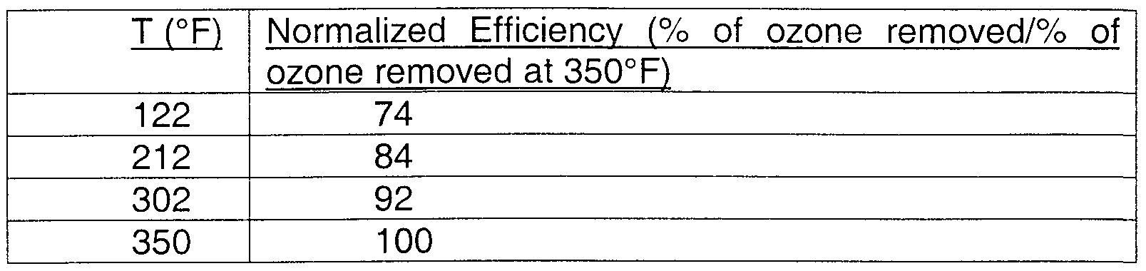
- An alumina alloy monolith having an offset fin construction was prepared per EXAMPLE II.
- the monolith was tested in a stream of 1 ppm ozone in air at 250,000 GHSV and 45 psig. The following excellent efficiency was observed:
- This example demonstrates the excellent low-temperature efficiency of ozone conversion.
- a set of fins was removed from the monolith following the test in EXAMPLE III and tested in a stream of 2.5 ppm ozone in air at 1 ,000,000 GHSV and 3 psig. The following efficiency was observed
- the SEM revealed that the washcoat layer was highly porous while the anodized layer had a rough surface texture at the interface with the washcoat layer and was dense at the interface with the aluminum core. These are preferred morphologies for promoting catalytic decomposition of ozone during the operation and for providing strong bonding between the washcoat and anodized layers with the metal substrate during the catalytic operation as well as catalyst preparation.
- a high degree of metal and metal oxide dispersion over the washcoat and anodized layers was verified by X-ray diffraction (XRD) and CO adsorption isotherm methods. For example, the CO adsorption isotherm measurement indicated that the Pd in the catalyst had the dispersion index greater than 50%.
- XANES X-ray absorption near edge structure
- XPS X-ray photoelectron spectroscopic
- EXAFS Extended X-ray absorption fine structure
- STEM scanning transmission electron microscopy
- anodized aluminum layer provides improved binding strength for the washcoat layer and better corrosion resistance during the catalyzing
- a pair of aluminum plates A and B having dimensions of 1 "x 2" x 1/16" was prepared.
- the first plate A was cleaned with an industrial detergent followed by rinsing with deionized water.
- the second plate B was subjected to the anodization in the oxalic acid to form an anodized layer, as described in EXAMPLE I. Both plates were washcoated and subsequently catalyzed following the procedure described in EXAMPLE I.
- a thermal cycling test was conducted for an ozone destruction catalytic monolith prepared according to the procedure in EXAMPLE II to evaluate the mechanical durability of the washcoat layer and the catalyst under repeated thermal stress condition.
- the monolith was subjected to continuous airflow with inlet air pressure of approximately 100 psig and a flow rate of 100 lb/minute.
- the temperature of the air was varied between 150 °F to 500 °F with a temperature ramp rate of 75 °F /minute.
- a total of 2000 thermal cycles was conducted during the test.
- the washcoat layer and catalyst weight loss was measured at the end of the test cycle. It was found that the washcoat layer and catalyst had excellent mechanical resistance to thermal stress and that the total weight loss was less than 2% after the test.
- a vibration test was conducted for an ozone destruction catalytic monolith prepared per EXAMPLE II to evaluate the mechanical durability of the washcoat layer and the catalyst under severe vibrations.
- the monolith was mounted on a vibration test stand and was subject to 15 hours of random vibrations in both longitudinal and transversal directions. Frequency was 10 Hz to 2000 Hz and 4.0 g rms in the longitudinal direction and 10 Hz to 2000 Hz at 9.54 g rms in the transveral direction.
- the mechanical integrity of the monolith was inspected, and the washcoat layer and catalyst weight loss were measured at the end of the vibration test. It was found that the monolith had no structural damage or variation. Furthermore, it was found that the washcoat layer and catalyst had excellent mechanical resistance to vibrational stress and that the total weight loss is less than 1 % after the test.
- the washcoat layer may be applied directly to an unanodized core.
- a core may be made of stainless steel or titanium that has been baked or otherwise oxidized at the surface. If the core is made of a material that already has a porous or oxidized surface, the washcoat layer may be applied directly to the surface of such a core.
- the invention is not limited to the washcoat layer 26 described above.
- a washcoat layer including a metal oxide mixed with a water- based binder e.g., alumina sol, silica sol
- a water- based binder e.g., alumina sol, silica sol
- washcoat layers may not display the superior characteristics of the washcoat layer 26 described above.
- the catalyst 28 is not limited to any particular type and composition.
- the catalyst 28 may be monometallic or bimetallic, or it may include more than two metals. Therefore, the catalyst may include at least two precious metals. It may also include at least one transition metal.
- the core 22 is not limited to a single washcoating. Several washcoats may be performed to control uniformity of the washcoat layer 26.
Abstract
Description

Claims
Priority Applications (3)
| Application Number | Priority Date | Filing Date | Title |
|---|---|---|---|
| EP99969351A EP1112117B1 (en) | 1998-09-18 | 1999-09-17 | Catalytic converter for removing ozone having anodized and washcoat layers |
| DE69916858T DE69916858T2 (en) | 1998-09-18 | 1999-09-17 | CATALYTIC CONVERTER FOR REMOVING OZONE WITH ANODIZED LAYER AND COATING |
| JP2000573837A JP2003526554A (en) | 1998-09-18 | 1999-09-17 | Catalytic converter for removing ozone with anodized and thin-coated layers |
Applications Claiming Priority (4)
| Application Number | Priority Date | Filing Date | Title |
|---|---|---|---|
| US10114098P | 1998-09-18 | 1998-09-18 | |
| US60/101,140 | 1998-09-18 | ||
| US09/379,036 | 1999-08-23 | ||
| US09/379,036 US6576199B1 (en) | 1998-09-18 | 1999-08-23 | Environmental control system including ozone-destroying catalytic converter having anodized and washcoat layers |
Publications (1)
| Publication Number | Publication Date |
|---|---|
| WO2000016882A1 true WO2000016882A1 (en) | 2000-03-30 |
Family
ID=26797938
Family Applications (1)
| Application Number | Title | Priority Date | Filing Date |
|---|---|---|---|
| PCT/US1999/021635 WO2000016882A1 (en) | 1998-09-18 | 1999-09-17 | Catalytic converter for removing ozone having anodized and washcoat layers |
Country Status (6)
| Country | Link |
|---|---|
| US (3) | US6576199B1 (en) |
| EP (1) | EP1112117B1 (en) |
| JP (1) | JP2003526554A (en) |
| DE (1) | DE69916858T2 (en) |
| ES (1) | ES2220144T3 (en) |
| WO (1) | WO2000016882A1 (en) |
Cited By (14)
| Publication number | Priority date | Publication date | Assignee | Title |
|---|---|---|---|---|
| WO2005000467A1 (en) | 2003-03-03 | 2005-01-06 | Honeywell International Inc. | Combined hydrocarbon/ozone converter for airplane bleed air system |
| WO2015061477A1 (en) * | 2013-10-22 | 2015-04-30 | SDCmaterials, Inc. | Catalyst design for heavy-duty diesel combustion engines |
| WO2015143225A1 (en) * | 2014-03-21 | 2015-09-24 | SDCmaterials, Inc. | Compositions for passive nox adsorption (pna) systems |
| US9180423B2 (en) | 2005-04-19 | 2015-11-10 | SDCmaterials, Inc. | Highly turbulent quench chamber |
| US9302260B2 (en) | 2007-10-15 | 2016-04-05 | SDCmaterials, Inc. | Method and system for forming plug and play metal catalysts |
| US9308524B2 (en) | 2009-12-15 | 2016-04-12 | SDCmaterials, Inc. | Advanced catalysts for automotive applications |
| US9332636B2 (en) | 2009-12-15 | 2016-05-03 | SDCmaterials, Inc. | Sandwich of impact resistant material |
| US9433938B2 (en) | 2011-02-23 | 2016-09-06 | SDCmaterials, Inc. | Wet chemical and plasma methods of forming stable PTPD catalysts |
| US9498751B2 (en) | 2011-08-19 | 2016-11-22 | SDCmaterials, Inc. | Coated substrates for use in catalysis and catalytic converters and methods of coating substrates with washcoat compositions |
| US9511352B2 (en) | 2012-11-21 | 2016-12-06 | SDCmaterials, Inc. | Three-way catalytic converter using nanoparticles |
| US9517448B2 (en) | 2013-10-22 | 2016-12-13 | SDCmaterials, Inc. | Compositions of lean NOx trap (LNT) systems and methods of making and using same |
| US9522388B2 (en) | 2009-12-15 | 2016-12-20 | SDCmaterials, Inc. | Pinning and affixing nano-active material |
| US9533299B2 (en) | 2012-11-21 | 2017-01-03 | SDCmaterials, Inc. | Three-way catalytic converter using nanoparticles |
| US9586179B2 (en) | 2013-07-25 | 2017-03-07 | SDCmaterials, Inc. | Washcoats and coated substrates for catalytic converters and methods of making and using same |
Families Citing this family (40)
| Publication number | Priority date | Publication date | Assignee | Title |
|---|---|---|---|---|
| US6576199B1 (en) * | 1998-09-18 | 2003-06-10 | Alliedsignal Inc. | Environmental control system including ozone-destroying catalytic converter having anodized and washcoat layers |
| DE10038525C2 (en) * | 2000-08-08 | 2002-11-21 | Ballard Power Systems | Catalyst connection disk for a stacked reactor and method for producing the catalyst connection disk |
| US7635461B2 (en) * | 2003-06-06 | 2009-12-22 | University Of Utah Research Foundation | Composite combustion catalyst and associated methods |
| JP2005021880A (en) * | 2003-06-13 | 2005-01-27 | Nissan Motor Co Ltd | Exhaust gas cleaning catalyst and exhaust gas cleaning catalyst system |
| US7271125B2 (en) * | 2004-01-14 | 2007-09-18 | Engelhard Corporation | Coated metal substrate |
| US7732084B2 (en) * | 2004-02-04 | 2010-06-08 | General Electric Company | Solid oxide fuel cell with internal reforming, catalyzed interconnect for use therewith, and methods |
| US7250141B2 (en) * | 2004-02-27 | 2007-07-31 | Honeywell International, Inc. | Augmented catalytic heat exchanger system |
| US7473402B2 (en) * | 2004-03-26 | 2009-01-06 | Honeywell International, Inc. | Ozone removal system and method for low and high temperature operation |
| US7541012B2 (en) * | 2004-07-07 | 2009-06-02 | The Hong Kong University Of Science And Technology | Catalytic material and method of production thereof |
| US20060078479A1 (en) * | 2004-10-07 | 2006-04-13 | Caterpillar Inc. | Filter assembly for an exhaust treatment device |
| DE102004051945B4 (en) * | 2004-10-25 | 2013-04-11 | Anseros Klaus Nonnenmacher Gmbh | Apparatus and method for the destruction of ozone from gases with integrated heat exchanger |
| US20060231908A1 (en) * | 2005-04-13 | 2006-10-19 | Xerox Corporation | Multilayer gate dielectric |
| ITMI20051410A1 (en) * | 2005-07-22 | 2007-01-23 | Eni Spa | PROCEDURE FOR THE PREPARATION OF FISCHER-TROPSCH CATALYSTS WITH HIGH MECHANICAL, THERMAL AND CHEMICAL STABILITY |
| JP5081830B2 (en) * | 2005-10-13 | 2012-11-28 | ヴェロシス インコーポレイテッド | Electroless plating in microchannels |
| US7462339B2 (en) * | 2005-12-29 | 2008-12-09 | Basf Catalysts Llc | Metallic foam trap for poisons: aircraft ozone |
| US20070245928A1 (en) * | 2006-03-10 | 2007-10-25 | Bennert Jeff E | Hydrated catalytic coating |
| US7678169B1 (en) | 2006-07-12 | 2010-03-16 | Cummins Filtration Ip Inc. | Oil fill cap with air/oil separator |
| EP2243541B1 (en) * | 2006-09-08 | 2012-12-05 | Parker Hannifin Manufacturing Netherlands (Filtration and Separation) B.V. | Sytem for aircraft air treatment comprising an ozone conversion means |
| US8389432B2 (en) * | 2006-09-25 | 2013-03-05 | Umicore Ag & Co. Kg | Structured automotive catalyst with improved thermal ageing stability |
| US7887764B2 (en) * | 2007-09-18 | 2011-02-15 | Jernberg Gary R | Mixer with a catalytic surface |
| US20090227195A1 (en) * | 2008-03-07 | 2009-09-10 | Basf Catalysts Llc | Systems and Methods for Treating Aircraft Cabin Air |
| US8716165B2 (en) | 2008-04-30 | 2014-05-06 | Corning Incorporated | Catalysts on substrates and methods for providing the same |
| US20100086457A1 (en) * | 2008-10-08 | 2010-04-08 | General Electric Company | Catalyst and method of manufacture |
| US20100152032A1 (en) * | 2008-12-16 | 2010-06-17 | Basf Catalysts Llc | Aircraft Air Treatment Catalysts, Systems and Methods |
| US20100158775A1 (en) * | 2008-12-18 | 2010-06-24 | Basf Catalysts Llc | Catalyst Systems and Methods for Treating Aircraft Cabin Air |
| KR101626541B1 (en) * | 2009-11-19 | 2016-06-01 | 에스케이이노베이션 주식회사 | The Catalysts for Selective Oxidation of NH3 to N2 and Their Preparation Methods |
| US8765625B2 (en) * | 2009-12-10 | 2014-07-01 | Shubin, Inc. | Engine exhaust catalysts containing copper-ceria |
| US20110152068A1 (en) * | 2009-12-17 | 2011-06-23 | General Electric Company | Processing of high surface area oxides |
| US20110152064A1 (en) * | 2009-12-17 | 2011-06-23 | General Electric Company | Processing of high surface area oxides |
| US8323747B2 (en) | 2010-06-25 | 2012-12-04 | Uop Llc | Zeolite containing wash coats for adsorber heat exchangers and temperature controlled adsorbers |
| US8394331B2 (en) | 2011-07-22 | 2013-03-12 | Honeywell International Inc. | Next generation combined hydrocarbon/ozone converter |
| US9279626B2 (en) * | 2012-01-23 | 2016-03-08 | Honeywell International Inc. | Plate-fin heat exchanger with a porous blocker bar |
| US9266092B2 (en) | 2013-01-24 | 2016-02-23 | Basf Corporation | Automotive catalyst composites having a two-metal layer |
| US8960123B2 (en) * | 2013-02-08 | 2015-02-24 | Enki Technology, Inc. | Coating and curing apparatus and methods |
| US20140255261A1 (en) * | 2013-03-07 | 2014-09-11 | Ford Global Technologies, Llc | Cellular substrate for a catalytic convertor |
| CN114768793A (en) | 2013-10-30 | 2022-07-22 | 巴斯夫公司 | Catalyst coating for pollution control |
| US9314811B1 (en) | 2015-05-11 | 2016-04-19 | Enki Technology, Inc. | Coating and curing apparatus and methods |
| US10266272B2 (en) * | 2016-08-16 | 2019-04-23 | Hamilton Sundstrand Corporation | Catalytic ozone removal |
| US10851461B2 (en) * | 2017-03-31 | 2020-12-01 | Hamilton Sunstrand Corporation | Treated anodized metal article and method of making |
| US11883796B2 (en) | 2021-02-09 | 2024-01-30 | Honeywell International Inc. | High efficiency combined hydrocarbon and ozone converter |
Citations (4)
| Publication number | Priority date | Publication date | Assignee | Title |
|---|---|---|---|---|
| EP0388094A1 (en) * | 1989-03-10 | 1990-09-19 | Sakai Chemical Industry Co., Ltd., | Methods of ozone decomposition and catalyst structures used therein |
| WO1994009903A1 (en) * | 1992-10-28 | 1994-05-11 | Allied-Signal Inc. | Catalytic converter with metal monolith having an integral catalyst |
| WO1995032053A1 (en) * | 1994-05-23 | 1995-11-30 | W.R. Grace & Co.-Conn. | Metal foil catalyst members by aqueous electrophoretic deposition |
| EP0853142A1 (en) * | 1997-01-14 | 1998-07-15 | Takenaka Corporation | Metal material having photocatalytic activity and method of manufacturing the same |
Family Cites Families (16)
| Publication number | Priority date | Publication date | Assignee | Title |
|---|---|---|---|---|
| US3262830A (en) * | 1961-04-19 | 1966-07-26 | Dow Corning | Organosilicon molding compositions containing orthotitanate catalysts |
| US3441381A (en) * | 1965-06-22 | 1969-04-29 | Engelhard Ind Inc | Apparatus for purifying exhaust gases of an internal combustion engine |
| US3472668A (en) * | 1968-05-31 | 1969-10-14 | Owens Corning Fiberglass Corp | Reinforcement of lower density inorganic structures |
| US4013573A (en) * | 1975-04-22 | 1977-03-22 | The Procter & Gamble Company | Carrier granule for an organosilane |
| FR2431324B1 (en) | 1978-07-17 | 1986-05-23 | Sharp Kk | SELF-CLEANING COATING COMPOSITIONS CONTAINING AN OXIDATION CATALYST AND COOKING APPARATUS COATED WITH SUCH COMPOSITIONS |
| JPS6138659Y2 (en) | 1979-10-04 | 1986-11-07 | ||
| US4279782A (en) * | 1980-03-31 | 1981-07-21 | General Motors Corporation | Application of an alumina coating to oxide whisker-covered surface on Al-containing stainless steel foil |
| DE3044948A1 (en) * | 1980-11-28 | 1982-07-01 | Wacker-Chemie GmbH, 8000 München | METHOD FOR PRODUCING BLOCKS OR COMPONENTS |
| US4405507A (en) | 1980-12-22 | 1983-09-20 | Engelhard Corporation | Ozone abatement catalyst having improved durability and low temperature performance |
| EP0161692B1 (en) | 1981-11-05 | 1988-02-03 | Mitsubishi Denki Kabushiki Kaisha | Sound-absorbing device for use as muffler for exhaust gas from an internal combustion engine |
| JP3309971B2 (en) * | 1990-03-30 | 2002-07-29 | 東京濾器株式会社 | Manufacturing method of exhaust gas purifying catalyst |
| US5227093A (en) * | 1991-11-29 | 1993-07-13 | Dow Corning Corporation | Curable organosiloxane compositions yielding electrically conductive materials |
| US5422311A (en) | 1993-05-03 | 1995-06-06 | Hyundai Electronics Industries Co., Ltd. | Method for manufacturing a conductor layer in a semiconductor device |
| US5422331A (en) | 1994-02-25 | 1995-06-06 | Engelhard Corporation | Layered catalyst composition |
| CA2206435A1 (en) * | 1995-01-20 | 1996-07-25 | Michael Spencer | Pollutant treating device located in vehicle compartment for cleaning ambient air |
| US6576199B1 (en) * | 1998-09-18 | 2003-06-10 | Alliedsignal Inc. | Environmental control system including ozone-destroying catalytic converter having anodized and washcoat layers |
-
1999
- 1999-08-23 US US09/379,036 patent/US6576199B1/en not_active Expired - Lifetime
- 1999-09-17 DE DE69916858T patent/DE69916858T2/en not_active Expired - Fee Related
- 1999-09-17 EP EP99969351A patent/EP1112117B1/en not_active Expired - Lifetime
- 1999-09-17 WO PCT/US1999/021635 patent/WO2000016882A1/en active IP Right Grant
- 1999-09-17 ES ES99969351T patent/ES2220144T3/en not_active Expired - Lifetime
- 1999-09-17 JP JP2000573837A patent/JP2003526554A/en not_active Withdrawn
-
2003
- 2003-05-07 US US10/431,477 patent/US7037878B2/en not_active Expired - Lifetime
-
2005
- 2005-09-16 US US11/228,949 patent/US7604779B2/en not_active Expired - Fee Related
Patent Citations (4)
| Publication number | Priority date | Publication date | Assignee | Title |
|---|---|---|---|---|
| EP0388094A1 (en) * | 1989-03-10 | 1990-09-19 | Sakai Chemical Industry Co., Ltd., | Methods of ozone decomposition and catalyst structures used therein |
| WO1994009903A1 (en) * | 1992-10-28 | 1994-05-11 | Allied-Signal Inc. | Catalytic converter with metal monolith having an integral catalyst |
| WO1995032053A1 (en) * | 1994-05-23 | 1995-11-30 | W.R. Grace & Co.-Conn. | Metal foil catalyst members by aqueous electrophoretic deposition |
| EP0853142A1 (en) * | 1997-01-14 | 1998-07-15 | Takenaka Corporation | Metal material having photocatalytic activity and method of manufacturing the same |
Cited By (26)
| Publication number | Priority date | Publication date | Assignee | Title |
|---|---|---|---|---|
| WO2005000467A1 (en) | 2003-03-03 | 2005-01-06 | Honeywell International Inc. | Combined hydrocarbon/ozone converter for airplane bleed air system |
| US7629290B2 (en) | 2003-03-03 | 2009-12-08 | Honeywell International Inc. | Low-temperature ozone catalyst |
| US9180423B2 (en) | 2005-04-19 | 2015-11-10 | SDCmaterials, Inc. | Highly turbulent quench chamber |
| US9719727B2 (en) | 2005-04-19 | 2017-08-01 | SDCmaterials, Inc. | Fluid recirculation system for use in vapor phase particle production system |
| US9599405B2 (en) | 2005-04-19 | 2017-03-21 | SDCmaterials, Inc. | Highly turbulent quench chamber |
| US9216398B2 (en) | 2005-04-19 | 2015-12-22 | SDCmaterials, Inc. | Method and apparatus for making uniform and ultrasmall nanoparticles |
| US9302260B2 (en) | 2007-10-15 | 2016-04-05 | SDCmaterials, Inc. | Method and system for forming plug and play metal catalysts |
| US9737878B2 (en) | 2007-10-15 | 2017-08-22 | SDCmaterials, Inc. | Method and system for forming plug and play metal catalysts |
| US9597662B2 (en) | 2007-10-15 | 2017-03-21 | SDCmaterials, Inc. | Method and system for forming plug and play metal compound catalysts |
| US9592492B2 (en) | 2007-10-15 | 2017-03-14 | SDCmaterials, Inc. | Method and system for forming plug and play oxide catalysts |
| US9308524B2 (en) | 2009-12-15 | 2016-04-12 | SDCmaterials, Inc. | Advanced catalysts for automotive applications |
| US9332636B2 (en) | 2009-12-15 | 2016-05-03 | SDCmaterials, Inc. | Sandwich of impact resistant material |
| US9533289B2 (en) | 2009-12-15 | 2017-01-03 | SDCmaterials, Inc. | Advanced catalysts for automotive applications |
| US9522388B2 (en) | 2009-12-15 | 2016-12-20 | SDCmaterials, Inc. | Pinning and affixing nano-active material |
| US9433938B2 (en) | 2011-02-23 | 2016-09-06 | SDCmaterials, Inc. | Wet chemical and plasma methods of forming stable PTPD catalysts |
| US9498751B2 (en) | 2011-08-19 | 2016-11-22 | SDCmaterials, Inc. | Coated substrates for use in catalysis and catalytic converters and methods of coating substrates with washcoat compositions |
| US9511352B2 (en) | 2012-11-21 | 2016-12-06 | SDCmaterials, Inc. | Three-way catalytic converter using nanoparticles |
| US9533299B2 (en) | 2012-11-21 | 2017-01-03 | SDCmaterials, Inc. | Three-way catalytic converter using nanoparticles |
| US9586179B2 (en) | 2013-07-25 | 2017-03-07 | SDCmaterials, Inc. | Washcoats and coated substrates for catalytic converters and methods of making and using same |
| US9566568B2 (en) | 2013-10-22 | 2017-02-14 | SDCmaterials, Inc. | Catalyst design for heavy-duty diesel combustion engines |
| US9517448B2 (en) | 2013-10-22 | 2016-12-13 | SDCmaterials, Inc. | Compositions of lean NOx trap (LNT) systems and methods of making and using same |
| US9427732B2 (en) | 2013-10-22 | 2016-08-30 | SDCmaterials, Inc. | Catalyst design for heavy-duty diesel combustion engines |
| WO2015061477A1 (en) * | 2013-10-22 | 2015-04-30 | SDCmaterials, Inc. | Catalyst design for heavy-duty diesel combustion engines |
| US9950316B2 (en) | 2013-10-22 | 2018-04-24 | Umicore Ag & Co. Kg | Catalyst design for heavy-duty diesel combustion engines |
| US9687811B2 (en) | 2014-03-21 | 2017-06-27 | SDCmaterials, Inc. | Compositions for passive NOx adsorption (PNA) systems and methods of making and using same |
| WO2015143225A1 (en) * | 2014-03-21 | 2015-09-24 | SDCmaterials, Inc. | Compositions for passive nox adsorption (pna) systems |
Also Published As
| Publication number | Publication date |
|---|---|
| DE69916858D1 (en) | 2004-06-03 |
| EP1112117A1 (en) | 2001-07-04 |
| US6576199B1 (en) | 2003-06-10 |
| US7037878B2 (en) | 2006-05-02 |
| US20030202916A1 (en) | 2003-10-30 |
| ES2220144T3 (en) | 2004-12-01 |
| DE69916858T2 (en) | 2005-05-12 |
| EP1112117B1 (en) | 2004-04-28 |
| JP2003526554A (en) | 2003-09-09 |
| US20060062704A1 (en) | 2006-03-23 |
| US7604779B2 (en) | 2009-10-20 |
Similar Documents
| Publication | Publication Date | Title |
|---|---|---|
| EP1112117B1 (en) | Catalytic converter for removing ozone having anodized and washcoat layers | |
| US7629290B2 (en) | Low-temperature ozone catalyst | |
| CN109641196B (en) | Palladium diesel oxidation catalyst | |
| US5422331A (en) | Layered catalyst composition | |
| Nijhuis et al. | Preparation of monolithic catalysts | |
| US20070099796A1 (en) | Exhaust gas purifying catalyst and method of manufacturing the same | |
| JP6797114B2 (en) | Base metal catalyst for treating ozone and volatile organic compounds present in the air source | |
| EP1499422B1 (en) | Tubular catalytic pollutants removal and precooler device | |
| EP0666776B1 (en) | Catalytic converter with metal monolith having an integral catalyst | |
| US20100152032A1 (en) | Aircraft Air Treatment Catalysts, Systems and Methods | |
| GB1590606A (en) | Catalyst manufacture | |
| JP2022526899A (en) | Layered three-metal catalyst article and method for manufacturing catalyst article | |
| US20190388838A1 (en) | Catalyst composition comprising colloidal platinum group metal nanoparticles | |
| CN113260454A (en) | Layered three-way conversion (TWC) catalysts and methods of making the same | |
| KR20210102417A (en) | Catalyst articles and methods of making and using the same | |
| JP5126762B2 (en) | Honeycomb catalyst for carbon monoxide methanation, method for producing the catalyst, and method for methanation of carbon monoxide using the catalyst | |
| EP1366801A2 (en) | Catalytic converter for removing ozone having un-anodized and washcoat layers | |
| CN114728235A (en) | Emission control catalyst article with PGM rich zone | |
| JP4507717B2 (en) | Exhaust gas purification catalyst | |
| KR100536966B1 (en) | Catalyst using metal carrier and manufacturing method thereof | |
| WO1998006479A9 (en) | Environmental control system incorporating a dual bed reactor | |
| CN116367919A (en) | Ternary conversion catalyst composition comprising platinum-rhodium bimetallic component | |
| CN115916397A (en) | Emission control catalyst article with PGM gradient structure | |
| CN114786811A (en) | Emission control catalyst article with PGM-rich zone, method and apparatus for producing the same |
Legal Events
| Date | Code | Title | Description |
|---|---|---|---|
| AK | Designated states |
Kind code of ref document: A1 Designated state(s): JP |
|
| AL | Designated countries for regional patents |
Kind code of ref document: A1 Designated state(s): AT BE CH CY DE DK ES FI FR GB GR IE IT LU MC NL PT SE |
|
| 121 | Ep: the epo has been informed by wipo that ep was designated in this application | ||
| DFPE | Request for preliminary examination filed prior to expiration of 19th month from priority date (pct application filed before 20040101) | ||
| ENP | Entry into the national phase |
Ref country code: JP Ref document number: 2000 573837 Kind code of ref document: A Format of ref document f/p: F |
|
| WWE | Wipo information: entry into national phase |
Ref document number: 1999969351 Country of ref document: EP |
|
| WWP | Wipo information: published in national office |
Ref document number: 1999969351 Country of ref document: EP |
|
| WWG | Wipo information: grant in national office |
Ref document number: 1999969351 Country of ref document: EP |