WO1997013484A1 - Liquid-absorbent article and method and apparatus for manufacturing the absorbent article - Google Patents

Liquid-absorbent article and method and apparatus for manufacturing the absorbent article Download PDF

Info

Publication number
WO1997013484A1
WO1997013484A1 PCT/CA1996/000626 CA9600626W WO9713484A1 WO 1997013484 A1 WO1997013484 A1 WO 1997013484A1 CA 9600626 W CA9600626 W CA 9600626W WO 9713484 A1 WO9713484 A1 WO 9713484A1
Authority
WO
WIPO (PCT)
Prior art keywords
liquid
absorbent
absorbent article
zone
layer
Prior art date
Application number
PCT/CA1996/000626
Other languages
French (fr)
Inventor
Martin Roy
Louis Canuel
Original Assignee
Johnson & Johnson Inc.
Priority date (The priority date is an assumption and is not a legal conclusion. Google has not performed a legal analysis and makes no representation as to the accuracy of the date listed.)
Filing date
Publication date
Application filed by Johnson & Johnson Inc. filed Critical Johnson & Johnson Inc.
Priority to EP96930001A priority Critical patent/EP0927015A1/en
Priority to AU69220/96A priority patent/AU6922096A/en
Publication of WO1997013484A1 publication Critical patent/WO1997013484A1/en

Links

Classifications

    • AHUMAN NECESSITIES
    • A61MEDICAL OR VETERINARY SCIENCE; HYGIENE
    • A61FFILTERS IMPLANTABLE INTO BLOOD VESSELS; PROSTHESES; DEVICES PROVIDING PATENCY TO, OR PREVENTING COLLAPSING OF, TUBULAR STRUCTURES OF THE BODY, e.g. STENTS; ORTHOPAEDIC, NURSING OR CONTRACEPTIVE DEVICES; FOMENTATION; TREATMENT OR PROTECTION OF EYES OR EARS; BANDAGES, DRESSINGS OR ABSORBENT PADS; FIRST-AID KITS
    • A61F13/00Bandages or dressings; Absorbent pads
    • A61F13/15Absorbent pads, e.g. sanitary towels, swabs or tampons for external or internal application to the body; Supporting or fastening means therefor; Tampon applicators
    • A61F13/53Absorbent pads, e.g. sanitary towels, swabs or tampons for external or internal application to the body; Supporting or fastening means therefor; Tampon applicators characterised by the absorbing medium
    • A61F13/534Absorbent pads, e.g. sanitary towels, swabs or tampons for external or internal application to the body; Supporting or fastening means therefor; Tampon applicators characterised by the absorbing medium having an inhomogeneous composition through the thickness of the pad
    • AHUMAN NECESSITIES
    • A61MEDICAL OR VETERINARY SCIENCE; HYGIENE
    • A61FFILTERS IMPLANTABLE INTO BLOOD VESSELS; PROSTHESES; DEVICES PROVIDING PATENCY TO, OR PREVENTING COLLAPSING OF, TUBULAR STRUCTURES OF THE BODY, e.g. STENTS; ORTHOPAEDIC, NURSING OR CONTRACEPTIVE DEVICES; FOMENTATION; TREATMENT OR PROTECTION OF EYES OR EARS; BANDAGES, DRESSINGS OR ABSORBENT PADS; FIRST-AID KITS
    • A61F13/00Bandages or dressings; Absorbent pads
    • A61F13/15Absorbent pads, e.g. sanitary towels, swabs or tampons for external or internal application to the body; Supporting or fastening means therefor; Tampon applicators
    • A61F13/53Absorbent pads, e.g. sanitary towels, swabs or tampons for external or internal application to the body; Supporting or fastening means therefor; Tampon applicators characterised by the absorbing medium
    • A61F2013/530131Absorbent pads, e.g. sanitary towels, swabs or tampons for external or internal application to the body; Supporting or fastening means therefor; Tampon applicators characterised by the absorbing medium being made in fibre but being not pulp
    • A61F2013/530335Absorbent pads, e.g. sanitary towels, swabs or tampons for external or internal application to the body; Supporting or fastening means therefor; Tampon applicators characterised by the absorbing medium being made in fibre but being not pulp being in peat moss
    • AHUMAN NECESSITIES
    • A61MEDICAL OR VETERINARY SCIENCE; HYGIENE
    • A61FFILTERS IMPLANTABLE INTO BLOOD VESSELS; PROSTHESES; DEVICES PROVIDING PATENCY TO, OR PREVENTING COLLAPSING OF, TUBULAR STRUCTURES OF THE BODY, e.g. STENTS; ORTHOPAEDIC, NURSING OR CONTRACEPTIVE DEVICES; FOMENTATION; TREATMENT OR PROTECTION OF EYES OR EARS; BANDAGES, DRESSINGS OR ABSORBENT PADS; FIRST-AID KITS
    • A61F13/00Bandages or dressings; Absorbent pads
    • A61F13/15Absorbent pads, e.g. sanitary towels, swabs or tampons for external or internal application to the body; Supporting or fastening means therefor; Tampon applicators
    • A61F13/53Absorbent pads, e.g. sanitary towels, swabs or tampons for external or internal application to the body; Supporting or fastening means therefor; Tampon applicators characterised by the absorbing medium
    • A61F2013/530481Absorbent pads, e.g. sanitary towels, swabs or tampons for external or internal application to the body; Supporting or fastening means therefor; Tampon applicators characterised by the absorbing medium having superabsorbent materials, i.e. highly absorbent polymer gel materials
    • A61F2013/530583Absorbent pads, e.g. sanitary towels, swabs or tampons for external or internal application to the body; Supporting or fastening means therefor; Tampon applicators characterised by the absorbing medium having superabsorbent materials, i.e. highly absorbent polymer gel materials characterized by the form
    • AHUMAN NECESSITIES
    • A61MEDICAL OR VETERINARY SCIENCE; HYGIENE
    • A61FFILTERS IMPLANTABLE INTO BLOOD VESSELS; PROSTHESES; DEVICES PROVIDING PATENCY TO, OR PREVENTING COLLAPSING OF, TUBULAR STRUCTURES OF THE BODY, e.g. STENTS; ORTHOPAEDIC, NURSING OR CONTRACEPTIVE DEVICES; FOMENTATION; TREATMENT OR PROTECTION OF EYES OR EARS; BANDAGES, DRESSINGS OR ABSORBENT PADS; FIRST-AID KITS
    • A61F13/00Bandages or dressings; Absorbent pads
    • A61F13/15Absorbent pads, e.g. sanitary towels, swabs or tampons for external or internal application to the body; Supporting or fastening means therefor; Tampon applicators
    • A61F13/53Absorbent pads, e.g. sanitary towels, swabs or tampons for external or internal application to the body; Supporting or fastening means therefor; Tampon applicators characterised by the absorbing medium
    • A61F2013/530868Absorbent pads, e.g. sanitary towels, swabs or tampons for external or internal application to the body; Supporting or fastening means therefor; Tampon applicators characterised by the absorbing medium characterized by the liquid distribution or transport means other than wicking layer
    • A61F2013/530897Absorbent pads, e.g. sanitary towels, swabs or tampons for external or internal application to the body; Supporting or fastening means therefor; Tampon applicators characterised by the absorbing medium characterized by the liquid distribution or transport means other than wicking layer having capillary means, e.g. pore or fibre size gradient

Definitions

  • the invention relates to the art of manufacturing
  • the invention relates to a highly absorbent article that has a porosity gradient along the direction of fluid migration there through.
  • the invention also extends to a method and apparatus for manufacturing the absorbent article.
  • absorbent cores made primarily of cellulosic pulp fluff material. Such cores are generally soft, flexible and absorbent but tend to be bulky and thick and have poor wicking properties. In addition, cellulosic pulp fluff material has poor structural stability which may cause the absorbent core to collapse when saturated with liquid.
  • An absorbent structure that has poor wicking properties usually increases the likelihood of failure of the absorbent product to hold and contain body liquids.
  • Body exudate will be localized to a certain area of the poorly wicking absorbent medium, causing localized saturation whereby excess liquid may overflow through an external surface of the absorbent product. This overflow may contact the user's garment and cause stains or contact the user's body and cause wet discomfort or rash.
  • the improved wicking properties of such an absorbent core provide the capacity for liquids to travel by capillary pressure throughout the entire absorbent volume.
  • an absorbent structure comprising sphagnum moss as a primary absorbent component is formed as a sheet by air or wet laying of particles.
  • the sheet is calendered to obtain a relatively thin, i.e. from about 0.025 to about 0.25 centimeters (cm) thick and relatively dense, i.e. from about 0.1 to about 1.0 grams per cubic centimeter (g/cc) structure.
  • Such absorbent sphagnum moss sheet may be processed to increase its flexibility for enhancing its comfort potential by subjecting the sheet to mechanical tenderizing such as a perf-embossing or a micro-corrugating process.
  • the sphagnum moss sheet thus formed has a large proportion of extremely tiny pores and capillaries allowing the sheet to absorb and retain a very high amount of liquid.
  • the sphagnum moss pores swell as they absorb liquid, however, this swelling does not cause a loss of capacity for further admitting liquid. Rather, the swelling contributes to the ability of the absorbent medium to retain the liquid while generally maintaining the structural integrity of the absorbent structure in use.
  • the wicking properties of the above-described sphagnum moss sheet provide the ability for the sheet to be highly absorbent while remaining relatively thin.
  • sphagnum moss Although sphagnum moss has certain highly desirable liquid-absorption properties, It manifests less than ideal fluid-acquisition rates. To overcome this difficulty it is common practice to provide a highly permeable, fibrous, liquid transfer layer on the sphagnum moss layer, whose function is to quickly collect the body exudate and then meter the liquid to the sphagnum moss material. Liquid discharged on such composite absorbent structure will rapidly ingress the transfer layer due to its highly porous network. From the transfer layer, liquid migrates toward the sphagnum moss layer by capillary pressure as a result of the substantial difference in wicking power between the different materials. The liquid migrat ion is well-controlled, occurring at the rate of acceptance of the sphagnum moss.
  • Another object of this invention is to provide a disposable absorbent product, such as a sanitary napkin, a diaper, an incontinence pad, an adult brief, a wound dressing, a nursing pad, a tampon pledget, or a desiccant for packaging materials, which utilizes a sphagnum moss absorbent core having a significantly improved liquid acgulsition rate.
  • a disposable absorbent product such as a sanitary napkin, a diaper, an incontinence pad, an adult brief, a wound dressing, a nursing pad, a tampon pledget, or a desiccant for packaging materials, which utilizes a sphagnum moss absorbent core having a significantly improved liquid acgulsition rate.
  • Another object of this invention is to provide a novel method and apparatus for manufacturing a liquid-absorbent article which utilizes a sphagnum moss absorbent core having a significantly improved liquid acquisition rate.
  • the present invention provides a liquid-absorbent article comprising absorbent particulate material and further comprising first and second zones in intimate fluid communicative relationship, each zone having a multiplicity of inter-particle and intra-particle interstices admitting passage of liquid, said first zone having a larger average interstice size than said second zone, whereby said second zone manifests a higher capillary attraction than said first zone.
  • the terminology "particle” shall mean fibrous as well as non-fibrous materials, i.e., any small unit of material without limitations of shape.
  • a fiber that is characterized as having a geometrical extension along a preferential direction will be considered a particle.
  • "particulate material” includes materials made of fibers, particles having non-fibrous identity, or a combination of both.
  • inter-particle interstices refers solely to the interstices defined between the particles, while “intra-particle interstices” refers to an open cellular structure inside the particles, such as the lumen in sphagnum moss leaves.
  • average interstice size refers to both the intra-particle interstices and the inter-particle interstices.
  • Suitable materials include, for example, sphagnum, perlite, vermiculite, expanded clay, expanded rice, crushed foam, zeolite, and combinations thereof are suitable for use in the present invention.
  • Sphagnum is the preferred material for use in the present invention due to its highly absorbent nature.
  • intimate fluid-communicative relationship refers to a condition in which liquid in one of the zones can easily migrate toward the other zone. This condition is achieved when the zones are co-formed or when they have been formed as discrete elements and then joined to one another by means to create an interface providing a path of comparatively low resistance to the migration of liquid. Suitable means for joining the zones include, but are not limited to, adhesive, thermobonding, needle punching, and the like, and combinations thereof.
  • absorbent structures having a porosity gradient of the type broadly defined above provide a significant advantage to absorbent products.
  • the first zone has an open network that rapidly admits the discharge of body exudate into the absorbent structure.
  • the second zone has a less open network which provides a strong capillary attraction differential between the two zones, whereby the liquid is preferentially drawn toward the second zone where it is permanently entrapped.
  • the increase in the fluid take-up rate of the provided by the absorbent structure of the present invention permits a disposable absorbent product to utilize a thinner transfer layer without increasing the risk of failure by overflow leakage. For some applications, the transfer layer may even be dispensed with.
  • the average interstice size of a given zone of the liquid-absorbent article may be controlled by one or more of the following expedients:
  • A) adjusting the proportion between inter-particle interstices and intra-particle interstices in the liquid-absorbent material For example, an increase in the relative amount of particles having intra-particle interstices in the liquid-absorbent material, wherein the intra-particle interstices are smaller than the inter-particle interstices, will cause the average interstice size of the liquid-absorbent material to diminish.
  • sphagnum moss has lumen (i.e. intra-particle interstice) whose average size is typically below 66 microns. Accordingly, a relative increase in the amount of sphagnum moss in the liquid-absorbent material will result in a reduction in the average interstice size. Conversely, a relative decrease in the ratio intra-particle interstices/inter-particle interstices, results in an increase in the average interstice size.
  • the size of inter-particle interstices of the material is proportional to the size of the particles.
  • the incorporation of coarse particles into a liquid- absorbent material will result in a liquid-absorbent article having larger interstices than would be obtained by the use of fine particles.
  • This allows one to regulate the average interstice size by varying the average particle size of the material.
  • the average interstice size of a material may be increased by introducing in the absorbent material non-porous particles that are relatively large. The non-porous character of the particles increases the ratio inter-particle interstices/intra-particles interstices while the coarseness of the particles augments the average inter- particle size.
  • the compression may affect both the inter-particle interstice and the intra-particle interstice sizes.
  • any of the steps A to D applied alone or in combination can be used to control the average interstice size of individual zones of the liquid-absorbent to optimize the porosity gradient in the liquid-absorbent product.
  • the liquid-absorbent product includes a lower layer made of sphagnum moss material on top of which is integrally formed an upper layer that combines sphagnum moss and debonding component.
  • the purpose of the debonding component is to increase the average interstice size in the sphagnum moss network and provide therein interstices that are significantly larger than the interstices of the lower layer.
  • debonding component shall mean any material which is capable of reducing the cohesiveness of a given particulate liquid- absorbent material, such as an agent acting chemically to reduce the bonds uniting the particles of the material to one another, or a physical separator that forcibly maintains the particles in a spaced apart relationship, hence increasing the average interstice size of the network.
  • a suitable debonding component manifesting a physical separator activity is cross-linked cellulosic fibers.
  • Suitable cross-linked cellulosic fibers for use in this invention are disclosed in US patent 4,853,086, assigned to Weyerhaeuser Company, dated August 1, 1989, which describes a method for manufacturing cross- linked cellulosic fibers which consists of spraying a wet or partially dry web of cellulosic fibers with an aqueous solution of glycol and dialdehyde.
  • US patent 4,853,086, assigned to Weyerhaeuser Company dated August 1, 1989
  • a method for manufacturing cross- linked cellulosic fibers which consists of spraying a wet or partially dry web of cellulosic fibers with an aqueous solution of glycol and dialdehyde.
  • the disclosure of this patent is incorporated herein by reference in its entirety.
  • the porosity gradient is obtained by forming the various layers of the liquid-absorbent sheet from sphagnum moss particles having different dimensions. More particularly, the upper layer is formed of sphagnum moss particles that are relatively coarse i.e. larger than the particles in the lower layer. When those particles are amalgamated together during the formation process of the absorbent sheet, large inter-particle interstices remain between them. In contrast, the lower layer is formed primarily of fine sphagnum moss particles that, due to their smaller size, fit closer to one another to provide inter-particle interstices of lesser dimensions.
  • a hybrid structure combining the features of the two previously described embodiments is the most preferred.
  • the characterizing feature of this variant is the inclusion of debonding component into the upper laver of coarse sphagnum moss particles.
  • the debonding component may be a chemical agent or a physical separator such as cross-linked fibers.
  • the layer of coarse sphagnum moss particles has a particle size median value in the range from about 2000 microns to about 500 microns.
  • the fine layer of sphagnum moss particles has a particle size median value in the range from about 500 microns to about 150 microns.
  • the layer of coarse sphagnum moss particles having a median particle of about 2000 microns has significantly more inter-particle interstices in the size range from about 600 microns to about 120 microns, by comparison to a fine layer of sphagnum moss where no separation has been made between coarse and fine sphagnum moss particles, and thus has a lesser amount of inter-particle interstices in the size range from about 600 microns to about 120 microns than the coarse sphagnum layer.
  • the coarse layer of sphagnum moss has at least about 55% of inter-particle interstices (in term of interstice count rather than interstice volume) having a size in the range from about 600 microns to about 120 microns, more preferably at least about 60% of inter-particle interstices in that range and most preferably at least about 63% of inter-particle interstices in that range.
  • any interstice in sphagnum moss material having a size in excess of 66 microns is considered to be an inter-particle interstice rather than an intra-particle interstice, since the intra-particle interstices (lumen) on the sphagnum leaves are substantially smaller than 66 microns.
  • the invention also provides a liquid-absorbent article including first and second zones in fluid-communicative relationship, said first zone and said second zone including sphagnum moss particles, said first zone having a larger proportion of inter-particle interstices (in terms of interstice count rather than interstice volume) in a size range from about 600 microns to about 120 microns than said second zone.
  • the absorbent article is not necessarily an integrally formed structure.
  • the various zones which preferably form individual layers of the article may be discrete elements that are united with adhesive or by another suitable means.
  • the invention also provides a liquid-absorbent article including first and second zones in fluid-communicative relationship, said first zone including sphagnum moss particles having a first particle size median value, said second zone having a second particle size median value.
  • the invention also provides a disposable absorbent product, comprising!
  • an absorbent component of particulate material said absorbent component including upper and lower layers in intimate fluid communicative relationship, each zone having a multiplicity of inter-particle and intra-particle interstices admitting passage of liquid, said first zone having a larger average interstice size than said second zone, whereby said lower zone manifests a higher capillary attraction than said upper laver in order to induce liquid absorbed in said upper laver to migrate toward said lower layer;
  • the invention further provides a method for manufacturing a liquid absorbent component, said method comprising the steps of:
  • the first and the second zones include sphagnum moss and are manufactured by a co-forming process which includes the following steps:
  • the co-forming process broadly described above greatly simplifies the manufacture of the liquid-absorbent article in accordance with the invention because the formation and bonding of the layers is accomplished in a single operation.
  • a further advantage of this method resides in the strength of the bond between the layers which is highly resistant to delamination. As a result, the liquid-absorbent article can withstand vigorous mechanical working without loosing its structural integrity. Further, the bond is such as to establish the desirable intimate fluid-communicative relationship allowing fluid to easily migrate from the upper layer towards the lower layer.
  • the slurries forming the respective layers of the liquid-absorbent article are laid in a superposed relationship on a continuously advancing Fourdrinier wire to form the laminated composite slurry layer.
  • the Fourdrinier wire is passed over a vacuum slot establishing a pressure differential across the laminated composite slurry layer to extract water therefrom.
  • the resulting web is dried, calendered and cut into discrete absorbent components. If desired, the web may be subjected to mechanical working, such as perf-embossing or micro-corrugating, in order to increase its flexibility for a better comfort potential.
  • composition of the individual slurry layers determines the final structure of the liquid-absorbent sheet.
  • porosity gradient is achieved solely by the inclusion of debonding component in the upper layer, the selected debonding component is added to the slurry before laying the slurry on the Fourdrinier wire.
  • the manufacturing process begins by preparing a mother slurry containing sphagnum moss particles of varying sizes. The slurry is then subjected to a classification step to separate the mother slurry in at least two slurry fractions according to the size of the sphagnum moss particles. The slurry fractions are then laid in a superposed relationship on a Fourdrinier wire as described above.
  • the sphagnum moss particle separation is followed by the addition of debonding component in the slurry fraction containing the coarse sphagnum moss particles.
  • the layers of the absorbent article are formed as discrete elements that are ultimately united by adhesive bonding or by any other suitable agency to form a laminated structure having strata of different average interstice sizes.
  • the layers are manufactured by separating a mother slurry of sphagnum moss into coarse and fine fractions, and then laying the fractions separately to form the individual layers. After the usual post-format ion treatments, such as drying, pressing, calendering, etc., the layers are united to one another in a superposed relationship.
  • the manufacture of the liquid absorbent article conducted by assembling together discrete absorbent layers is perhaps less desirable than the integral formation approach, primarily because additional manipulations are required to complete the manufacture of the absorbent article.
  • the interface between the discrete layers provides a liquid path of somewhat higher resistance than when the layers are integrally formed. Still, this embodiment exhibits significantly improved liquid-absorbent properties by comparison to prior art structures and it thus suitable for many applications.
  • the invention further provides a method for manufacturing a laminated liquid-absorbent article, comprising the steps of:
  • the liquid communicative relationship between the absorbent layers is created by co-formation, such as wet laying the slurry fractions in a superposed relationship, as described earlier.
  • This approach produces an integrally formed liquid-absorbent article.
  • the absorbent layers may be formed separately from one another and then assembled by adhesive bonding or the like to establish the liquid-communicative relationship between them.
  • the invention also provides an apparatus for manufacturing a highly absorbent structurally integral article having superposed liquid-absorbent layers united in an intimate fluid-communicative relationship, said apparatus comprising: a classifier for separating particles suspended in fluidizing medium into at least two slurry fractions in accordance to size of said particles, a first slurry fraction having a larger particle size median than a second slurry fraction, said classifier having first and second outlets for discharging said first and second slurry fractions, respectively;
  • the fluid absorbent article in accordance with the present invention is suitable for use in disposable absorbent products including, but not limited to sanitary napkins, diapers, urinary pads, adult briefs, wound dressing, nursing pads, tampon pledgets, or as desiccants for packaging materials to keep goods dry during shipping or storage.
  • FIG. 1 is a fragmentary, perspective view of a sanitary napkin incorporating the liquid-absorbent article according to the invention:
  • FIG. 2 is a fragmentary perspective view of the liquid-absorbent article according to the present invention that is characterized by a non-uniform porosity distribution;
  • FIG. 3 is a schematic representation of an apparatus for manufacturing the compound, structurally integral, liquid-absorbent article in accordance with the invention
  • FIG. 4 is a flowchart of the process for manufacturing the liquid-absorbent article in accordance with the invention.
  • FIG. 5 is a flowchart of the process for manufacturing the liquid-absorbent article in accordance with a variant
  • FIG. 6 is a flowchart of the process for manufacturing the liquid-absorbent article in accordance with a further variant
  • - Figure 7 is a perspective view of a liquid-absorbent article manufactured by assembling in a superposed relationship separately formed discrete absorbent layers; and - Figure 8 is a porosity distribution graph of the liquid-absorbent article and some of its component layers.
  • the sanitary napkin 10 designates comprehensively a sanitary napkin constructed in accordance with the principles of the present invention.
  • the sanitary napkin 10 comprises an envelope 12 defining an internal space receiving an absorbent component 56 that includes sphagnum moss.
  • the envelope 12 includes a liquid permeable cover layer 16 made of a non-woven fabric or any other suitable porous web or apertured film, and a liquid impervious backing layer 18, made of polyethylene film for example.
  • the cover and backing layers 16 and 18 are heat-sealed to one another along their marginal portions.
  • the liquid impervious backing layer 18 may be provided with adhesive zones covered with a peelable backing (not shown in the drawings).
  • the absorbent component 56 is a dual-layer structure featuring a porosity gradient along the Z direction.
  • a transfer layer (not shown in the drawings) of known construction is provided over the absorbent component with a view of further enhancing the liquid acquisition rate of the sanitary napkin.
  • the structure of the absorbent component 56 is shown in Figure 2. It comprises a central core 58 containing primarily sphagnum moss and having a porosity gradient along the Z direction (the thickness).
  • the central core 58 is constituted by an upper layer 60a and a lower layer 60b intermixed at the interface to provide an intimate liquid-communicative relationship between them.
  • Layer 60a has a larger average interstice size than layer 60b.
  • the central core 58 is confined between reinforcing layers 62 and 64 of fibrous material.
  • the purpose of the reinforcing layers is twofold. First, they strengthen the core 58, thereby providing a unitized absorbent structure capable of maintaining its integrity even when saturated with liquid. Second, the layers 62 and 64 reduce dusting by preventing free sphagnum moss particles within the absorbent structure from being released outside. Kraft wood pulp material has been found highly satisfactory for manufacturing the reinforcing layers 62 and 64. It is also possible to use other materials, such cotton linters or ground wood among others, in admixture with or in substitution to the Kraft wood pulp material.
  • the apparatus designated comprehensively by the reference numeral 18 comprises an endless, fluid-pervious Fourdrinier wire 26 which is mounted on rollers 28 to provide a horizontally extending run 30 that is continuously advanced forward to support and convey a slurry of sphagnum moss and cellulosic fibers through various processing stations.
  • Headboxes 32, 34, 66 and 36 arranged in a spaced apart relationship along the path of travel of the wire 26 are provided to lay on the wire 26 slurry in sheeted form.
  • the headbox bank deposits on the wire 26 four (4) layers of slurry in a superposed relationship to form a laminated slurry web. More specifically, the headboxes 34 and 66 lay slurries containing sphagnum moss while the headboxes 32 and 36 deliver slurries of fibrous material such as Kraft wood pulp or any other suitable substance.
  • the preparation of the sphagnum moss slurry layers supplied to headboxes 34 and 66 is illustrated by the flowchart of Figure 4.
  • the mother slurry prepared by dispersing raw sphagnum moss material in water is wet classified at steps 68 and 70 to retain only the particles having a size in the range from about 74 microns to about 2000 microns.
  • the screened fraction is diluted with water to render the slurry more manageable and supplied to a dual-stage classifier station 72 in order to separate the sphagnum moss particles in a fine fraction and a coarse fraction.
  • the classifier station 72 comprises a primary centrifugal classifier 74 to perform an initial separation of the sphagnum moss particles on the basis of size.
  • a centrifugal classifier available from Hymac Limited under any one of commercial designations RB 200, RB 150XC or RB 80X has been found satisfactory.
  • the centrifugal classifier 74 is calibrated to produce a reject stream having a particle size median in the range from about 2000 microns (10 mesh) to about 500 microns (35 mesh) that is directed at headbox 66.
  • the particle size median value is defined as the size of the particles having the highest frequency when the sphagnum moss particles are classified according to size.
  • a fibrous component such as polyester fibers and/or Kraft wood pulp at step 76 prior to supplying the slurry to headbox 66 that forms the layer 60a of the central core 58.
  • Suitable fibrous components may include such materials as Kraft wood pulp, cross-linked cellulosic fibers, mechanical wood pulp, natural or synthetic textile fibers such as rayon, polyester, nylon, acrylic and the like, and mixtures thereof.
  • the fibrous components are generally added to the headbox in an amount from 2 to 20% by weight of the absorbent sheet 10, preferably from 2% to 6%.
  • mechanical wood pulp is meant to include ground wood pulp, thermo-mechanical pulp and refiner wood pulp.
  • Ground wood pulp is essentially trees and branches which have been debarked, cleaned and ground into particulate matter.
  • Refiner wood pulp differs from ground wood pulp only in that the grinding step utilizes a refiner, i.e. a disc-like device well-known in the art and having metallic ribs at the peripheral sections thereof which last contact the wood particles and help separate the wood fibers without excessively damaging them.
  • Thermo-mechanical wood pulp is similar to refiner pulp with the exception that the wood particles are heated in the refiner, usually with steam, to aid in separating the wood fibers.
  • the common characteristic of these mechanical pulps is that no attempt has been made to separate the fibers by chemical means although they may later, after being reduced to fine particulate matter, be subjected to a desired chemical treatment, such as bleaching.
  • such mechanical pulp when used in a sphagnum moss slurry, such mechanical pulp has a Canadian Standard Freeness (TAPPI test method T-227), in a range of from about 60 to 750 and preferably from about 400 to 600.
  • TAPPI test method T-227 Canadian Standard Freeness
  • the Kraft wood pulp also usable in combination with sphagnum moss, is essentially chemically treated, long fibred wood pulp such as sulphite and sulphate wood pulps.
  • a debonding component is added to the slurry supplied to headbox 66 in an amount which is effective to increase the inter-particle interstices in the liquid-absorbent product.
  • Suitable debonding agents include, but are not limited to fibrous materials which are effective for reducing the cohesiveness of the particles in the liquid-absorbent product. These fibrous materials preferably have a length of from about 0.6 cm to about 1.9 cm, preferably about 1.3 cm and a denier of from about 1.0 to 5.0.
  • Preferred debonding components which have been found to be particularly effective in opening-up a sphagnum moss network in order to allow a faster liquid acquisition are cross-linked cellulosic fibers.
  • cross-linked cellulosic fibers are incorporated into the slurry in an amount effective to reduce the cohesiveness of the sphagnum moss particles in the liquid-absorbent product, i.e., open-up the sphagnum moss network.
  • the exact amount of cross-linked fibers can vary widely, depending on the nature and particle size of the sphagnum moss particles, and is preferably in the range from about 5% to about 75% based on the weight of solids in the slurry.
  • the slurry of coarse sphagnum moss particles may also contain an effective amount of a chemical debonding agent, of a type known in the art, which can be used either in combination or in substitution to the cross-linked cellulosic fibers.
  • the accepts stream of the centrifugal classifier 74 that contains sphagnum moss particles of smaller size is supplied to a 60 mesh stationary screen 78 of the type described in Canadian patent application 2,057,654 assigned to Johnson & Johnson Inc. laid open on June 14, 1993 which is incorporated herein by reference in its entirety.
  • the screen 78 features a system of jets directed at the screen plate to prevent the screen apertures from clogging.
  • the rejects stream that contains particles larger than about 150 microns (100 mesh) are discarded.
  • the accepts having an average particle size in the range from about 500 microns (35 mesh) to about 150 microns (100 mesh) are directed to headbox 34 to form layer 60b of the central core 58.
  • a stationary screen operating on the principle of a sieve be used in the second stage 78 than a centrifugal classifier because it allows a better process control.
  • a stationary screen may be substituted to the centrifugal classifier 74.
  • Such stationary screen is identical to screen 78 described above with the exception that screening apertures of 6.35 mm could be used rather than 60 mesh perforations.
  • a fibrous component may be added to the slurry, as shown as step 80.
  • the slurry fractions supplied to the headboxes 34 and 66 are prepared on the production line illustrated in Figure 5.
  • the difference with the set-up of Figure 4 resides in that no cross-linked cellulosic fibers are added to the flow of coarse sphagnum moss particles.
  • no separation of the sphagnum moss particles is made.
  • the slurry from the screening system 68 and 70 is split in two parts having approximately the same sphagnum moss particle size distribution.
  • cross- linked fibers or another debonding component is added to one of the slurry fractions from which the layer 60a is made.
  • a slurry of Kraft wood pulp layer having a consistency of about 0.2% by weight of solids is first laid down on the wire 26 from the headbox 32 in order to form the bottom Kraft reinforcing layer 64.
  • the slurry flow rate is selected to deliver on the wire 26, 15 grams of solids per square meter.
  • the Kraft slurry passes under the headbox 34 which delivers on top of the Kraft layer a slurry of fine sphagnum moss particles prepared with the installation of Figure 4.
  • the slurry has a sphagnum moss content in the range from about 80% to 100% by weight of solids in the slurry and contains polyester fibers up to 20% by weight.
  • the consistency of the sphagnum moss slurry fraction is set at 0.5% by weight of solids.
  • the flow rate of the slurry fraction is selected to deliver 178 grams of solids per square meter on the wire 26.
  • the headbox 66 delivers the slurry fraction of coarse sphagnum moss particles intermixed with cellulosic cross-linked fibers.
  • This slurry fraction has a consistency of 0.5% by weight of solids, a flow rate to deliver 182 grams of solids per square meter on the wire 20.
  • the coarse particles slurry contains sphagnum moss in the range from about 20% to 60% by weight of solids in the slurry, cross-linked cellulosic fibers in the range from about 5% to about 75% by weight and polyester fibers up to 20% by weight.
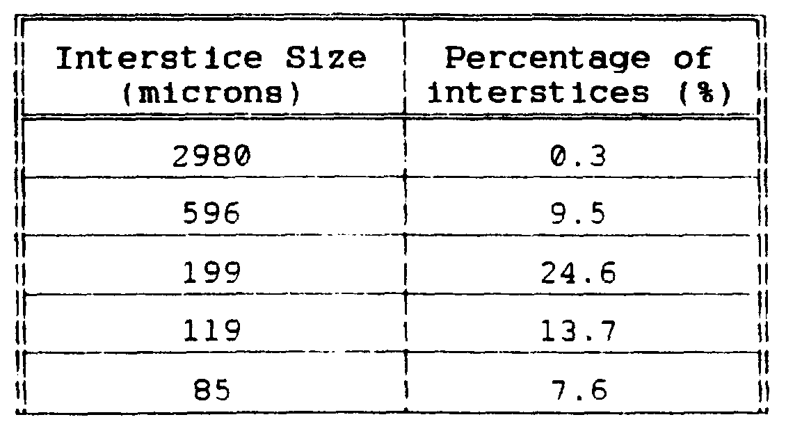
  • a liquid absorbent article was manufactured having the following formulation and porosity distribution profile as described below:
  • interstice size the interstice size and percentage of interstices are as follows:
  • the layer 60a (coarse sphagnum particles) had a significant amount of interstices in the size range from about 600 microns to about 120 microns.
  • layer 60a should have at least about 50% of interstices in the range 600 - 120 microns, more preferably at least about 60% and most preferably (in the embodiment shown) at least about 63%.
  • the layer 60b had less interstices in this size range (41% in the embodiment shown).
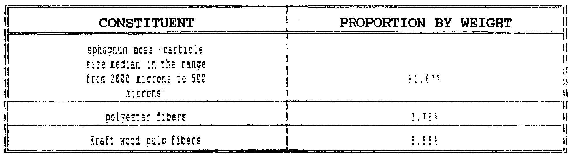
  • a second example of a formulation for the sphagnum moss slurry layers delivered from the headboxes 34 and 66 is as follows.
  • This formulation was prepared in accordance with the manufacturing process shown in Figure 5 and contained sphagnum moss in the range from about 68% to 100% by weight of solids in the slurry, polyester fibers up to 20% by weight and Kraft wood pulp fibers up to 30% by weight.
  • the slurry fractions coarse/fine differed primarily by the particle size of the sphagnum moss material.
  • the slurry fraction of primarily fine sphagnum moss particles was as follows:
  • the slurry fraction of primarily coarse sphagnum moss particles was as follows :
  • a third example of a formulation for the sphagnum moss slurry layers delivered from the headboxes 34 and 66 is as follows. This formulation was prepared in accordance with the manufacturing process shown in Figure 6. In this example, both slurry fractions have approximately the same sphagnum moss particle size distribution.
  • the lower slurry layer delivered from the headbox 34 had a sphagnum moss content in the range from about 80% to 100% by weight of solids in the slurry and contained polyester fibers up to 20% by weight.
  • the specific formulation is as follows:
  • the upper slurry fraction delivered from the headbox 66 contains sphagnum moss in the range from about 20% to about 60% by weight of solids in the slurry, cross-linked cellulosic fibers in the range from about 5% to about 75% by weight and polyester fibers up to 20% by weight.
  • sphagnum moss in the range from about 20% to about 60% by weight of solids in the slurry, cross-linked cellulosic fibers in the range from about 5% to about 75% by weight and polyester fibers up to 20% by weight.
  • a final Kraft wood pulp slurry layer was laid from the headbox 36 on the sphagnum moss slurry in order to form the reinforcing top layer 62.
  • This final layer was identical in terms of consistency and composition to the bottom Kraft wood pulp layer 64 previously deposited except that the flow rate was such as to deposit on a square meter of the wire 26 five grams of solids.
  • the resulting laminated slurry layer Kraft/Sphagnum/ Sphagnum/Kraft was then passed over a vacuum slot 50 to extract water under the influence of a pressure differential established across the slurry layer. It was necessary to regulate the residence time of the slurry layer over the vacuum slot 50 and the vacuum intensity in order to control the density of the final product. Generally, decreased vacuum and increased speed will result in a less dense product.
  • the web leaving the dewatering station 50 passed through a drier 52 whose purpose was to elevate the temperature of the web to evaporate residual water.
  • the drier 52 is of a
  • a press section (not shown in the drawings) to mechanically express water from the web, as it is well-known to those skilled in the art, in order to reduce the water contents in the web as much as possible before it is processed in the drier 52.
  • a calendering station 54 Downstream of the drier 52 a calendering station 54 is provided which mechanically compresses the dried product in order to densify the sphagnum moss material for enhancing Its drying power. If desired, the calendering station 54 may be followed by a perf-embossing station (not shown in the
  • micro-corrugating operation which is similar to the
  • liquid-absorbent structure is solely subjected to an embossing operation to create closely spaced hinge lines.
  • the absorbent article under the second embodiment may be treated with re-wetting agent.
  • re-wetting agent Preferably, an RL Thorowet re-wetting agent (available from Clough
  • a G-60 Thorowet re-wetting agent available from Clough Chemicals
  • Clough Chemicals is delivered on the Kraft /Sphagnum/ Sphagnum/Kraft laminated slurry layers, prior the dewatering stage in an amount of 0.8% by weight of solids in the absorbent article.
  • the G-60 Thorowet re-wetting agent is delivered on the top Kraft layer in a foamed condition, as described in the Canadian Patent
  • FIG 7. A variant of the liquid-absorbent article is illustrated in Figure 7.
  • This variant is characterized in that the layers 60a and 60b are formed as discrete entities and then united to form a compound liquid-absorbent structure, rather than being integrally formed.
  • the layers are manufactured by following the process steps illustrated in Figure 4 with the exception that headboxes 34 and 66 deposit the fine and the coarse slurry fractions on separate Fourdrinier wires (not shown in the drawings). Each slurry fraction is then subjected to independent post-format ion treatments, such as pressing, drying, calendering, etc.
  • the resulting absorbent layers are then united to one another in a superposed relationship by adhesive or any other suitable agency.
  • Sanitary napkins constructed with the liquid-absorbent article 56 as the absorbent core are found to possess a very high liquid-absorption capacity and a comparatively high liquid-penetration rate which reduces the risk of failure when a large quantity of body exudate is suddenly released on the sanitary napkin.
  • the control is an integrally formed sheet containing a central core of sphagnum moss having a uniform porosity distribution and united to two outer layers of Kraft wood pulp.
  • the central core contains 76.92% by weight of solids in the control sheet of sphagnum moss, 3.69% of polyester fibers and 7.38% of Kraft wood pulp.
  • Each of the top and bottom Kraft layers represent 4.61% of the control by weight of solids.
  • the control sheet also contains 0.92% by weight of solids of G-60 Thorowet re-wetting agent and 0.4% by weight of solids of RL Thorowet re-wetting agent that are applied as discussed earlier.
  • the basis weight of the control sheet is of 325 grams per meter squared.
  • the sanitary napkin control is manufactured by placing on the absorbent article as described above cut in the form of a 10 centimeter (cm) by 10 cm square, a transfer layer of identical dimensions.
  • the specific transfer layer used has a basis weight of 120 grams per meter squared and it is
  • Airtex 397 a 10 cm by 10 cm embossed hydrophillic apertured film is placed over the transfer layer.
  • the apertured film is known in the trade as wettable Reticulon and it is used to manufacture the cover layer of a sanitary napkin commercialized by Johnson & Johnson in Germany under the trademark Silhouette Ultra.
  • liquid absorbent article prepared by the process of Figure 4 is incorporated in a sanitary napkin construction as the absorbent core. This consists of placing on the liquid absorbent article the transfer layer and the cover layer used in the sanitary napkin control. The resulting product is then tested against the sanitary napkin control to assess the following
  • Purpose to determine the absorption capacity of an absorbent material.
  • Test procedure a disk of 90 mm diameter is cut from a sheet of the material to be tested. The dry weight of the disk is measured and recorded. The disk is deposited on the porous plate of a GATS (Gravimetric Absorbency Test System)
  • test fluid is allowed to ingress the sample through the porous plate for a period of 15 minutes.
  • the wetted sample is removed from the porous plate and weighted to determine the amount of test fluid uptake.
  • the absorption capacity is expressed in terms of volume of fluid absorbed (cubic centimeters (cc) or mllliliters (ml)) per gram of absorbent material. For ease of reference, however, the absorption capacity is reported in the above test results in mllliliters per pad of absorbent material in the form of a sheet of 20 cm X 5 cm having a weight of 4 grams (g).
  • Test fluid 1% NaCl solution
  • Test procedure the instrument disclosed in the US patent 5,361,627 assigned to Johnson & Johnson Inc that was issued on November 8, 1994 is used for this purpose.
  • a sample of the material to be tested in the form of a rectangle 5 cm by 20 cm is laid on a horizontal support surface.
  • 3 cc of test fluid is deposited on the virgin sample and the sensor of the instrument is placed in contact with the absorbing surface of the sample. After 30 minutes from the fluid discharge the pressure reading in millimeters of mercury (mmHg) is recorded.
  • mmHg millimeters of mercury
  • the sensor is removed, an additional load of 3 cc of test fluid is
  • Test fluid synthetic menstrual liquid with protein having a viscosity of 25 cps.
  • Purpose to determine fluid migration profile of test fluid in a sample material.
  • Test procedure a sample of the absorbent material in the form of a rectangle 10 cm X 10 cm is laid on a flat surface and 1 cc of test fluid is discharged in the center of the absorbent surface. After the liquid has disappeared the surface area of the stain is measured and recorded. A comparatively small surface area indicates that the absorbent material has a good wicking power in the Z direction (vertical).
  • Test fluid synthetic menstrual fluid with protein having a viscosity of 25 cps.
  • Test procedure the time required for a 5 cm X 20 cm sample to absorb 5 cc of test fluid fed to the sample from an
  • Test fluid synthetic menstrual fluid with protein having a viscosity of either 25 cps or 100 cps.
  • Purpose the purpose of this test is to assess the propensity of a fluid present in an absorbent material under pressure to wet back an adjacent surface in contact therewith.
  • Test Procedure the sample material to which has been
  • test fluid 10 cubic centimeters of test fluid is allowed to rest 15 minutes and it is covered with a NuGauze brand pad. A pressure of 10.48 kPa is applied over the NuGauze pad. After 3 minutes, the amount of fluid (mass) captured by the pad is measured and reported in percentage on the basis of the dry weight of the pad.
  • Test Fluid synthetic menstrual fluid with protein having a viscosity of 100 cps.
  • Test procedure the dry weight of each layer of the absorbent structure is recorded. The absorbent structure is then
  • test fluid is deposited on the absorbent surface of the structure. After 20 minutes following the test fluid discharge each layer of the absorbent structure is weighted to determine the individual amount of fluid take-up.
  • Test fluid synthetic menstrual fluid with protein having viscosity of 100 cps.
  • Purpose to determine the porosity distribution profile in an absorbent structure.
  • Test procedure A GATS (Gravimetric Absorbency Test System) is used to determine the amount of liquid retained in the sample at different hydrostatic negative pressures.
  • the results are then converted to interstice size values using a known formula.
  • the GATS apparatus uses a "medium" fritted disc (CANADAWIDE) having a 90 mm diameter.
  • the fritted disc is in liquid communication with a vertical burette containing test liquid.
  • the vertical distance between the meniscus in the burette and the top surface of the fritted disc on which the sample is deposited defines the hydrostatic pressure exerted on the sample.
  • the burette is continuously replenished with liquid at the same rate at which the liquid is being absorbed by the sample.
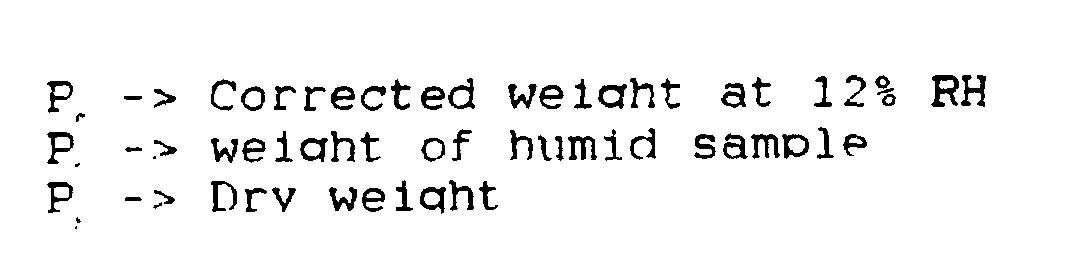
  • the corrected weight at 12% RH is:
  • the amount of liquid absorbed by the sample is then measured for the following neqat ive hydrostatic
  • interstice sizes is meant the equivalent interstice diameter.
  • test results clearly demonstrate the advantages of the liquid absorbent article in accordance with the invention. Note particularly the dramatic improvement in penetration time and capillary pressure over the control. The ability of such liquid absorbent article to manifest a powerful capillary attraction is particularly useful in sanitary napkin
  • the results of test I show that the liquid absorbent article in accordance with the invention collects virtually all the liquid discharged on the sanitary napkin, totally desorbing the cover layer and leaving only a small amount of liquid in the transfer layer.
  • the control has a less favorable fluid distribution pattern, with only 48 % of the total liquid discharge being contained in the absorbent core.

Abstract

A liquid-absorbent article having a high absorption capacity and a short fluid penetration time. The liquid-absorbent article has a porosity gradient along the Z direction (the thickness) established by superposing layers of absorbent material having different average pore sizes. In one embodiment the porous network of each absorbent layer is a combination of inter-particle and intra-particle interstices. In another embodiment the absorbent layers have different average particle sizes. The liquid-absorbent article is well-suited for use as an absorbent component of a disposable absorbent product, such as a sanitary napkin, a diaper, an incontinence pad, an adult brief, a wound dressing, a nursing pad, a tampon pledget, or as desiccant for packaging materials to keep goods dry during shipping or storage. The invention also extends to a novel method and apparatus for manufacturing the liquid-absorbent article.

Description

TITLE: LIQUID ABSORBENT ARTICLE AND METHOD AND APPARATUS FOR MANUFACTURING THE ABSORBENT ARTICLE
FIELD OF THE INVENTION
The invention relates to the art of manufacturing
structures for absorbing body exudate. More specifically, the invention relates to a highly absorbent article that has a porosity gradient along the direction of fluid migration there through. The invention also extends to a method and apparatus for manufacturing the absorbent article.
BACKGROUND OF THE INVENTION
Many disposable absorbent products use absorbent cores made primarily of cellulosic pulp fluff material. Such cores are generally soft, flexible and absorbent but tend to be bulky and thick and have poor wicking properties. In addition, cellulosic pulp fluff material has poor structural stability which may cause the absorbent core to collapse when saturated with liquid.
An absorbent structure that has poor wicking properties usually increases the likelihood of failure of the absorbent product to hold and contain body liquids. Body exudate will be localized to a certain area of the poorly wicking absorbent medium, causing localized saturation whereby excess liquid may overflow through an external surface of the absorbent product. This overflow may contact the user's garment and cause stains or contact the user's body and cause wet discomfort or rash. It is therefore desirable to provide an absorbent core for disposable absorbent products which can wick away body liquids from the point of contact with the absorbent core and spread it through the absorbent core. The improved wicking properties of such an absorbent core provide the capacity for liquids to travel by capillary pressure throughout the entire absorbent volume. This permits the use of thinner cores, since more absorbent volume can be made available for absorbing body liquids by such wicking action. Thinner absorbent cores may also prove to be more comfortable for the user and less unsightly or obvious when worn under clothes. Absorbent cores comprising sphagnum moss are described, for example, in the following US patents, the subject matter of which is incorporated herein by reference, in their entirety:
Figure imgf000004_0001
In accordance with the teaching of these patents, an absorbent structure comprising sphagnum moss as a primary absorbent component is formed as a sheet by air or wet laying of particles. The sheet is calendered to obtain a relatively thin, i.e. from about 0.025 to about 0.25 centimeters (cm) thick and relatively dense, i.e. from about 0.1 to about 1.0 grams per cubic centimeter (g/cc) structure. Such absorbent sphagnum moss sheet may be processed to increase its flexibility for enhancing its comfort potential by subjecting the sheet to mechanical tenderizing such as a perf-embossing or a micro-corrugating process.
The sphagnum moss sheet thus formed has a large proportion of extremely tiny pores and capillaries allowing the sheet to absorb and retain a very high amount of liquid. The sphagnum moss pores swell as they absorb liquid, however, this swelling does not cause a loss of capacity for further admitting liquid. Rather, the swelling contributes to the ability of the absorbent medium to retain the liquid while generally maintaining the structural integrity of the absorbent structure in use.
The wicking properties of the above-described sphagnum moss sheet provide the ability for the sheet to be highly absorbent while remaining relatively thin.
Although sphagnum moss has certain highly desirable liquid-absorption properties, It manifests less than ideal fluid-acquisition rates. To overcome this difficulty it is common practice to provide a highly permeable, fibrous, liquid transfer layer on the sphagnum moss layer, whose function is to quickly collect the body exudate and then meter the liquid to the sphagnum moss material. Liquid discharged on such composite absorbent structure will rapidly ingress the transfer layer due to its highly porous network. From the transfer layer, liquid migrates toward the sphagnum moss layer by capillary pressure as a result of the substantial difference in wicking power between the different materials. The liquid migrat ion is well-controlled, occurring at the rate of acceptance of the sphagnum moss.
Compound absorbent structures including transfer and reservoir layers are costly to produce because the raw material for manufacturing the transfer layer is expensive. Another drawback is the undesirable bulk increase of the disposable absorbent article resulting from the use of a thick transfer layer.
Hence, there is a need in the industry to provide a sphagnum moss absorbent core having a significantly improved liquid acquisition rate, thus allowing to employ a thinner transfer layer and possibly eliminate the transfer layer altogether.
SUMMARY OF THE INVENTION
It is an object of this invention to provide an absorbent article having a high liquid-acquisition rate and a high absorption capacity.
Another object of this invention is to provide a disposable absorbent product, such as a sanitary napkin, a diaper, an incontinence pad, an adult brief, a wound dressing, a nursing pad, a tampon pledget, or a desiccant for packaging materials, which utilizes a sphagnum moss absorbent core having a significantly improved liquid acgulsition rate.
Another object of this invention is to provide a novel method and apparatus for manufacturing a liquid-absorbent article which utilizes a sphagnum moss absorbent core having a significantly improved liquid acquisition rate.
As embodied and broadly described herein, the present invention provides a liquid-absorbent article comprising absorbent particulate material and further comprising first and second zones in intimate fluid communicative relationship, each zone having a multiplicity of inter-particle and intra-particle interstices admitting passage of liquid, said first zone having a larger average interstice size than said second zone, whereby said second zone manifests a higher capillary attraction than said first zone. For purposes of the present invention, the terminology "particle" shall mean fibrous as well as non-fibrous materials, i.e., any small unit of material without limitations of shape. Thus, a fiber that is characterized as having a geometrical extension along a preferential direction will be considered a particle. Hence, "particulate material" includes materials made of fibers, particles having non-fibrous identity, or a combination of both.
As used herein the terminology "inter-particle interstices" refers solely to the interstices defined between the particles, while "intra-particle interstices" refers to an open cellular structure inside the particles, such as the lumen in sphagnum moss leaves. The terminology "average interstice size" as used herein refers to both the intra-particle interstices and the inter-particle interstices. There exist many different porous materials which are capable of providing intra-particle interstices and thus are considered suitable for use in the manufacture of the liquid-absorbent article of the present invention. Suitable materials include, for example, sphagnum, perlite, vermiculite, expanded clay, expanded rice, crushed foam, zeolite, and combinations thereof are suitable for use in the present invention. Sphagnum, however, is the preferred material for use in the present invention due to its highly absorbent nature.
As used herein the terminology "intimate fluid-communicative relationship" refers to a condition in which liquid in one of the zones can easily migrate toward the other zone. This condition is achieved when the zones are co-formed or when they have been formed as discrete elements and then joined to one another by means to create an interface providing a path of comparatively low resistance to the migration of liquid. Suitable means for joining the zones include, but are not limited to, adhesive, thermobonding, needle punching, and the like, and combinations thereof.
It has now been discovered that absorbent structures having a porosity gradient of the type broadly defined above, provide a significant advantage to absorbent products. The first zone has an open network that rapidly admits the discharge of body exudate into the absorbent structure. The second zone has a less open network which provides a strong capillary attraction differential between the two zones, whereby the liquid is preferentially drawn toward the second zone where it is permanently entrapped. The increase in the fluid take-up rate of the provided by the absorbent structure of the present invention permits a disposable absorbent product to utilize a thinner transfer layer without increasing the risk of failure by overflow leakage. For some applications, the transfer layer may even be dispensed with. The average interstice size of a given zone of the liquid-absorbent article may be controlled by one or more of the following expedients:
A) adjusting the proportion between inter-particle interstices and intra-particle interstices in the liquid-absorbent material. For example, an increase in the relative amount of particles having intra-particle interstices in the liquid-absorbent material, wherein the intra-particle interstices are smaller than the inter-particle interstices, will cause the average interstice size of the liquid-absorbent material to diminish. For example, sphagnum moss has lumen (i.e. intra-particle interstice) whose average size is typically below 66 microns. Accordingly, a relative increase in the amount of sphagnum moss in the liquid-absorbent material will result in a reduction in the average interstice size. Conversely, a relative decrease in the ratio intra-particle interstices/inter-particle interstices, results in an increase in the average interstice size.
B) adjusting the size of the inter-particle interstices of the material. In general, the size of inter-particle interstices is proportional to the size of the particles. Hence, the incorporation of coarse particles into a liquid- absorbent material will result in a liquid-absorbent article having larger interstices than would be obtained by the use of fine particles. This allows one to regulate the average interstice size by varying the average particle size of the material. C) combining steps A and B. For example, the average interstice size of a material may be increased by introducing in the absorbent material non-porous particles that are relatively large. The non-porous character of the particles increases the ratio inter-particle interstices/intra-particles interstices while the coarseness of the particles augments the average inter- particle size.
D) applying mechanical compression to bring the particles closer to one another, thus decreasing the average interstice size. The compression may affect both the inter-particle interstice and the intra-particle interstice sizes.
Thus, anyone of the steps A to D applied alone or in combination can be used to control the average interstice size of individual zones of the liquid-absorbent to optimize the porosity gradient in the liquid-absorbent product.
Under one exemplary embodiment, the liquid-absorbent product includes a lower layer made of sphagnum moss material on top of which is integrally formed an upper layer that combines sphagnum moss and debonding component. The purpose of the debonding component is to increase the average interstice size in the sphagnum moss network and provide therein interstices that are significantly larger than the interstices of the lower layer. For the purpose of this specification "debonding component" shall mean any material which is capable of reducing the cohesiveness of a given particulate liquid- absorbent material, such as an agent acting chemically to reduce the bonds uniting the particles of the material to one another, or a physical separator that forcibly maintains the particles in a spaced apart relationship, hence increasing the average interstice size of the network. One example of a suitable debonding component manifesting a physical separator activity is cross-linked cellulosic fibers.
Suitable cross-linked cellulosic fibers for use in this invention are disclosed in US patent 4,853,086, assigned to Weyerhaeuser Company, dated August 1, 1989, which describes a method for manufacturing cross- linked cellulosic fibers which consists of spraying a wet or partially dry web of cellulosic fibers with an aqueous solution of glycol and dialdehyde. The disclosure of this patent is incorporated herein by reference in its entirety.
Under another exemplary embodiment, the porosity gradient is obtained by forming the various layers of the liquid-absorbent sheet from sphagnum moss particles having different dimensions. More particularly, the upper layer is formed of sphagnum moss particles that are relatively coarse i.e. larger than the particles in the lower layer. When those particles are amalgamated together during the formation process of the absorbent sheet, large inter-particle interstices remain between them. In contrast, the lower layer is formed primarily of fine sphagnum moss particles that, due to their smaller size, fit closer to one another to provide inter-particle interstices of lesser dimensions.
A hybrid structure combining the features of the two previously described embodiments is the most preferred. The characterizing feature of this variant is the inclusion of debonding component into the upper laver of coarse sphagnum moss particles. Again, the debonding component may be a chemical agent or a physical separator such as cross-linked fibers. Preferably, the layer of coarse sphagnum moss particles has a particle size median value in the range from about 2000 microns to about 500 microns. Preferably, the fine layer of sphagnum moss particles has a particle size median value in the range from about 500 microns to about 150 microns.
The layer of coarse sphagnum moss particles having a median particle of about 2000 microns has significantly more inter-particle interstices in the size range from about 600 microns to about 120 microns, by comparison to a fine layer of sphagnum moss where no separation has been made between coarse and fine sphagnum moss particles, and thus has a lesser amount of inter-particle interstices in the size range from about 600 microns to about 120 microns than the coarse sphagnum layer. In a preferred embodiment, the coarse layer of sphagnum moss has at least about 55% of inter-particle interstices (in term of interstice count rather than interstice volume) having a size in the range from about 600 microns to about 120 microns, more preferably at least about 60% of inter-particle interstices in that range and most preferably at least about 63% of inter-particle interstices in that range. For purposes of this specification, any interstice in sphagnum moss material having a size in excess of 66 microns is considered to be an inter-particle interstice rather than an intra-particle interstice, since the intra-particle interstices (lumen) on the sphagnum leaves are substantially smaller than 66 microns.
As embodied and broadly described herein, the invention also provides a liquid-absorbent article including first and second zones in fluid-communicative relationship, said first zone and said second zone including sphagnum moss particles, said first zone having a larger proportion of inter-particle interstices (in terms of interstice count rather than interstice volume) in a size range from about 600 microns to about 120 microns than said second zone.
Under this embodiment, the absorbent article is not necessarily an integrally formed structure. The various zones which preferably form individual layers of the article may be discrete elements that are united with adhesive or by another suitable means.
As embodied and broadly described herein, the invention also provides a liquid-absorbent article including first and second zones in fluid-communicative relationship, said first zone including sphagnum moss particles having a first particle size median value, said second zone having a second particle size median value.
As embodied and broadly described herein, the invention also provides a disposable absorbent product, comprising!
- an absorbent component of particulate material, said absorbent component including upper and lower layers in intimate fluid communicative relationship, each zone having a multiplicity of inter-particle and intra-particle interstices admitting passage of liquid, said first zone having a larger average interstice size than said second zone, whereby said lower zone manifests a higher capillary attraction than said upper laver in order to induce liquid absorbed in said upper laver to migrate toward said lower layer; and
- a body contacting, liquid-pervious cover layer superposed to said absorbent component.
As embodied and broadly described herein, the invention further provides a method for manufacturing a liquid absorbent component, said method comprising the steps of:
- providing a first zone of particulate material having a multiplicity of inter-particle and intra-particle interstices, said first zone having a first average interstice size;
- providing a second zone of particulate material having a multiplicity of inter-particle and intra-particle interstices, said second zone having a second average interstice size, said first interstice size being larger than said second interstice size; and
- establishing an intimate fluid communicative relationship between said zones to allow liquid in said first zone to migrate toward said second zone.
In a most preferred exemplary embodiment, the first and the second zones include sphagnum moss and are manufactured by a co-forming process which includes the following steps:
A) laying in a superposed relationship and in physical contact a first slurry layer of particulate material and a second slurry layer of particulate material to form a laminated composite slurry laver, the first and the second slurry layers including [effective amounts of] sphagnum moss particles, i) the first slurry layer constituting a precursor phase of a the first zone; ii) the second slurry layer constituting a precursor phase of the second zone;
B) extracting fluidizing medium from the laminated composite slurry layer to form a laminated composite web including the first zone and the second zone in a superposed condition and intimately united to one another.
The co-forming process broadly described above greatly simplifies the manufacture of the liquid-absorbent article in accordance with the invention because the formation and bonding of the layers is accomplished in a single operation. A further advantage of this method resides in the strength of the bond between the layers which is highly resistant to delamination. As a result, the liquid-absorbent article can withstand vigorous mechanical working without loosing its structural integrity. Further, the bond is such as to establish the desirable intimate fluid-communicative relationship allowing fluid to easily migrate from the upper layer towards the lower layer.
In a most preferred embodiment, the slurries forming the respective layers of the liquid-absorbent article are laid in a superposed relationship on a continuously advancing Fourdrinier wire to form the laminated composite slurry layer. The Fourdrinier wire is passed over a vacuum slot establishing a pressure differential across the laminated composite slurry layer to extract water therefrom. The resulting web is dried, calendered and cut into discrete absorbent components. If desired, the web may be subjected to mechanical working, such as perf-embossing or micro-corrugating, in order to increase its flexibility for a better comfort potential.
The composition of the individual slurry layers determines the final structure of the liquid-absorbent sheet. When the porosity gradient is achieved solely by the inclusion of debonding component in the upper layer, the selected debonding component is added to the slurry before laying the slurry on the Fourdrinier wire.
Under the embodiment that requires separation of the sphagnum moss in coarse particles and fine particles, the manufacturing process begins by preparing a mother slurry containing sphagnum moss particles of varying sizes. The slurry is then subjected to a classification step to separate the mother slurry in at least two slurry fractions according to the size of the sphagnum moss particles. The slurry fractions are then laid in a superposed relationship on a Fourdrinier wire as described above.
Under the hybrid embodiment the sphagnum moss particle separation is followed by the addition of debonding component in the slurry fraction containing the coarse sphagnum moss particles.
In a possible variant, the layers of the absorbent article are formed as discrete elements that are ultimately united by adhesive bonding or by any other suitable agency to form a laminated structure having strata of different average interstice sizes. In an exemplary embodiment the layers are manufactured by separating a mother slurry of sphagnum moss into coarse and fine fractions, and then laying the fractions separately to form the individual layers. After the usual post-format ion treatments, such as drying, pressing, calendering, etc., the layers are united to one another in a superposed relationship.
Objectively, the manufacture of the liquid absorbent article conducted by assembling together discrete absorbent layers is perhaps less desirable than the integral formation approach, primarily because additional manipulations are required to complete the manufacture of the absorbent article. In addition, the interface between the discrete layers provides a liquid path of somewhat higher resistance than when the layers are integrally formed. Still, this embodiment exhibits significantly improved liquid-absorbent properties by comparison to prior art structures and it thus suitable for many applications.
As embodied and broadly described herein, the invention further provides a method for manufacturing a laminated liquid-absorbent article, comprising the steps of:
- providing a body of particles suspended in fluid, such as liquid or gas, said particles having varying dimensions; separating said body of particles in at least two fractions, referenced as a first fraction and a second fraction, said first fraction having a higher particle size median value than said second fraction:
- extracting fluidizing medium from said fractions to form a first absorbent layer and a second absorbent layer respectively, said first absorbent layer having a higher average inter-particle interstice size than said second absorbent layer, whereby said second absorbent layer manifests a higher capillary attraction than said first absorbent layer;
- establishing a liquid-communicative relationship between said layers, whereby liquid introduced in said first layer is induced to migrate toward said second layer under the effect of capillary attraction.
In the most preferred embodiment, the liquid communicative relationship between the absorbent layers is created by co-formation, such as wet laying the slurry fractions in a superposed relationship, as described earlier. This approach produces an integrally formed liquid-absorbent article. In a variant, the absorbent layers may be formed separately from one another and then assembled by adhesive bonding or the like to establish the liquid-communicative relationship between them.
As embodied and broadly described herein, the invention also provides an apparatus for manufacturing a highly absorbent structurally integral article having superposed liquid-absorbent layers united in an intimate fluid-communicative relationship, said apparatus comprising: a classifier for separating particles suspended in fluidizing medium into at least two slurry fractions in accordance to size of said particles, a first slurry fraction having a larger particle size median than a second slurry fraction, said classifier having first and second outlets for discharging said first and second slurry fractions, respectively;
- a foraminous member;
- first and second headboxes in a fluid communicative relationship with said firs and second outlets respectively for discharging said first and second slurry fractions in a superposed relationship on said foraminous member to form a laminated composite slurry layer; and
- means for establishing a pressure differential across said laminated composite slurry layer to extract fluidizing medium from said first and second slurry fractions in order to form respective first and second porous networks intimately united to one another, said second porous network manifesting a higher capillary attraction than said first porous network to induce liquid absorbed in said first porous network to migrate toward said second porous network.
The fluid absorbent article in accordance with the present invention is suitable for use in disposable absorbent products including, but not limited to sanitary napkins, diapers, urinary pads, adult briefs, wound dressing, nursing pads, tampon pledgets, or as desiccants for packaging materials to keep goods dry during shipping or storage.
BRIEF DESCRIPTION OF THE DRAWINGS
- Figure 1 is a fragmentary, perspective view of a sanitary napkin incorporating the liquid-absorbent article according to the invention:
- Figure 2 is a fragmentary perspective view of the liquid-absorbent article according to the present invention that is characterized by a non-uniform porosity distribution;
- Figure 3 is a schematic representation of an apparatus for manufacturing the compound, structurally integral, liquid-absorbent article in accordance with the invention;
- Figure 4 is a flowchart of the process for manufacturing the liquid-absorbent article in accordance with the invention;
- Figure 5 is a flowchart of the process for manufacturing the liquid-absorbent article in accordance with a variant;
- Figure 6 is a flowchart of the process for manufacturing the liquid-absorbent article in accordance with a further variant;
- Figure 7 is a perspective view of a liquid-absorbent article manufactured by assembling in a superposed relationship separately formed discrete absorbent layers; and - Figure 8 is a porosity distribution graph of the liquid-absorbent article and some of its component layers.
DETAILED DESCRIPTION OF PREFERRED EMBODIMENTS
Referring now to Figure 1 of the annexed drawings, the reference numeral 10 designates comprehensively a sanitary napkin constructed in accordance with the principles of the present invention. The sanitary napkin 10 comprises an envelope 12 defining an internal space receiving an absorbent component 56 that includes sphagnum moss. The envelope 12 includes a liquid permeable cover layer 16 made of a non-woven fabric or any other suitable porous web or apertured film, and a liquid impervious backing layer 18, made of polyethylene film for example. The cover and backing layers 16 and 18 are heat-sealed to one another along their marginal portions. To attach the sanitary napkin 10 to the wearer's underpants, the liquid impervious backing layer 18 may be provided with adhesive zones covered with a peelable backing (not shown in the drawings).
The absorbent component 56 is a dual-layer structure featuring a porosity gradient along the Z direction. Preferably, a transfer layer (not shown in the drawings) of known construction is provided over the absorbent component with a view of further enhancing the liquid acquisition rate of the sanitary napkin.
The structure of the absorbent component 56 is shown in Figure 2. It comprises a central core 58 containing primarily sphagnum moss and having a porosity gradient along the Z direction (the thickness). The central core 58 is constituted by an upper layer 60a and a lower layer 60b intermixed at the interface to provide an intimate liquid-communicative relationship between them. Layer 60a has a larger average interstice size than layer 60b.
The central core 58 is confined between reinforcing layers 62 and 64 of fibrous material. The purpose of the reinforcing layers is twofold. First, they strengthen the core 58, thereby providing a unitized absorbent structure capable of maintaining its integrity even when saturated with liquid. Second, the layers 62 and 64 reduce dusting by preventing free sphagnum moss particles within the absorbent structure from being released outside. Kraft wood pulp material has been found highly satisfactory for manufacturing the reinforcing layers 62 and 64. It is also possible to use other materials, such cotton linters or ground wood among others, in admixture with or in substitution to the Kraft wood pulp material.
The detailed composition of the liquid-absorbent component 56 will be best understood from the following description of the apparatus and the process for manufacturing such absorbent component. Referring to Figure 3, the apparatus designated comprehensively by the reference numeral 18, comprises an endless, fluid-pervious Fourdrinier wire 26 which is mounted on rollers 28 to provide a horizontally extending run 30 that is continuously advanced forward to support and convey a slurry of sphagnum moss and cellulosic fibers through various processing stations.
Headboxes 32, 34, 66 and 36 arranged in a spaced apart relationship along the path of travel of the wire 26 are provided to lay on the wire 26 slurry in sheeted form. The headbox bank deposits on the wire 26 four (4) layers of slurry in a superposed relationship to form a laminated slurry web. More specifically, the headboxes 34 and 66 lay slurries containing sphagnum moss while the headboxes 32 and 36 deliver slurries of fibrous material such as Kraft wood pulp or any other suitable substance. The preparation of the sphagnum moss slurry layers supplied to headboxes 34 and 66 is illustrated by the flowchart of Figure 4. The mother slurry prepared by dispersing raw sphagnum moss material in water is wet classified at steps 68 and 70 to retain only the particles having a size in the range from about 74 microns to about 2000 microns. The screened fraction is diluted with water to render the slurry more manageable and supplied to a dual-stage classifier station 72 in order to separate the sphagnum moss particles in a fine fraction and a coarse fraction. The classifier station 72 comprises a primary centrifugal classifier 74 to perform an initial separation of the sphagnum moss particles on the basis of size. A centrifugal classifier available from Hymac Limited under any one of commercial designations RB 200, RB 150XC or RB 80X has been found satisfactory.
The centrifugal classifier 74 is calibrated to produce a reject stream having a particle size median in the range from about 2000 microns (10 mesh) to about 500 microns (35 mesh) that is directed at headbox 66. The particle size median value is defined as the size of the particles having the highest frequency when the sphagnum moss particles are classified according to size.
It is preferred to add a fibrous component, such as polyester fibers and/or Kraft wood pulp at step 76 prior to supplying the slurry to headbox 66 that forms the layer 60a of the central core 58. Suitable fibrous components may include such materials as Kraft wood pulp, cross-linked cellulosic fibers, mechanical wood pulp, natural or synthetic textile fibers such as rayon, polyester, nylon, acrylic and the like, and mixtures thereof. The fibrous components are generally added to the headbox in an amount from 2 to 20% by weight of the absorbent sheet 10, preferably from 2% to 6%. As used herein, the term mechanical wood pulp is meant to include ground wood pulp, thermo-mechanical pulp and refiner wood pulp. Ground wood pulp is essentially trees and branches which have been debarked, cleaned and ground into particulate matter. Refiner wood pulp differs from ground wood pulp only in that the grinding step utilizes a refiner, i.e. a disc-like device well-known in the art and having metallic ribs at the peripheral sections thereof which last contact the wood particles and help separate the wood fibers without excessively damaging them. Thermo-mechanical wood pulp is similar to refiner pulp with the exception that the wood particles are heated in the refiner, usually with steam, to aid in separating the wood fibers. The common characteristic of these mechanical pulps is that no attempt has been made to separate the fibers by chemical means although they may later, after being reduced to fine particulate matter, be subjected to a desired chemical treatment, such as bleaching. Preferably, when mechanical wood pulp is used in a sphagnum moss slurry, such mechanical pulp has a Canadian Standard Freeness (TAPPI test method T-227), in a range of from about 60 to 750 and preferably from about 400 to 600.
The Kraft wood pulp, also usable in combination with sphagnum moss, is essentially chemically treated, long fibred wood pulp such as sulphite and sulphate wood pulps.
Preferably, a debonding component is added to the slurry supplied to headbox 66 in an amount which is effective to increase the inter-particle interstices in the liquid-absorbent product. Suitable debonding agents include, but are not limited to fibrous materials which are effective for reducing the cohesiveness of the particles in the liquid-absorbent product. These fibrous materials preferably have a length of from about 0.6 cm to about 1.9 cm, preferably about 1.3 cm and a denier of from about 1.0 to 5.0. Preferred debonding components which have been found to be particularly effective in opening-up a sphagnum moss network in order to allow a faster liquid acquisition are cross-linked cellulosic fibers. In a preferred embodiment, cross-linked cellulosic fibers are incorporated into the slurry in an amount effective to reduce the cohesiveness of the sphagnum moss particles in the liquid-absorbent product, i.e., open-up the sphagnum moss network. The exact amount of cross-linked fibers can vary widely, depending on the nature and particle size of the sphagnum moss particles, and is preferably in the range from about 5% to about 75% based on the weight of solids in the slurry. The slurry of coarse sphagnum moss particles may also contain an effective amount of a chemical debonding agent, of a type known in the art, which can be used either in combination or in substitution to the cross-linked cellulosic fibers.
The accepts stream of the centrifugal classifier 74 that contains sphagnum moss particles of smaller size is supplied to a 60 mesh stationary screen 78 of the type described in Canadian patent application 2,057,654 assigned to Johnson & Johnson Inc. laid open on June 14, 1993 which is incorporated herein by reference in its entirety. The screen 78 features a system of jets directed at the screen plate to prevent the screen apertures from clogging. The rejects stream that contains particles larger than about 150 microns (100 mesh) are discarded. The accepts having an average particle size in the range from about 500 microns (35 mesh) to about 150 microns (100 mesh) are directed to headbox 34 to form layer 60b of the central core 58.
It is preferred that a stationary screen operating on the principle of a sieve be used in the second stage 78 than a centrifugal classifier because it allows a better process control. Similarly, a stationary screen, may be substituted to the centrifugal classifier 74. Such stationary screen is identical to screen 78 described above with the exception that screening apertures of 6.35 mm could be used rather than 60 mesh perforations.
At the completion of the classification stage, a fibrous component may be added to the slurry, as shown as step 80.
In a variant, the slurry fractions supplied to the headboxes 34 and 66 are prepared on the production line illustrated in Figure 5. The difference with the set-up of Figure 4 resides in that no cross-linked cellulosic fibers are added to the flow of coarse sphagnum moss particles. In a further variant shown in Figure 6, no separation of the sphagnum moss particles is made. The slurry from the screening system 68 and 70 is split in two parts having approximately the same sphagnum moss particle size distribution. To create the porosity gradient in the final product, cross- linked fibers or another debonding component is added to one of the slurry fractions from which the layer 60a is made.
In a first embodiment of the present invention, as illustrated in Figure 3, a slurry of Kraft wood pulp layer having a consistency of about 0.2% by weight of solids is first laid down on the wire 26 from the headbox 32 in order to form the bottom Kraft reinforcing layer 64. The slurry flow rate is selected to deliver on the wire 26, 15 grams of solids per square meter. The Kraft slurry passes under the headbox 34 which delivers on top of the Kraft layer a slurry of fine sphagnum moss particles prepared with the installation of Figure 4. The slurry has a sphagnum moss content in the range from about 80% to 100% by weight of solids in the slurry and contains polyester fibers up to 20% by weight.
A specific formulation that has been found satisfactory is reproduced below:
Figure imgf000027_0001
The consistency of the sphagnum moss slurry fraction is set at 0.5% by weight of solids. The flow rate of the slurry fraction is selected to deliver 178 grams of solids per square meter on the wire 26.
The headbox 66 delivers the slurry fraction of coarse sphagnum moss particles intermixed with cellulosic cross-linked fibers. This slurry fraction has a consistency of 0.5% by weight of solids, a flow rate to deliver 182 grams of solids per square meter on the wire 20. The coarse particles slurry contains sphagnum moss in the range from about 20% to 60% by weight of solids in the slurry, cross-linked cellulosic fibers in the range from about 5% to about 75% by weight and polyester fibers up to 20% by weight.
Example 1.
A liquid absorbent article was manufactured having the following formulation and porosity distribution profile as described below:
Figure imgf000028_0001
Figure imgf000028_0002
Figure imgf000029_0002
For comparison purposes, the porosity distribution of the individual layers of the liquid-absorbent article of this example was determined and provided in the following tables. The method for measuring the porosity distribution profiles is discussed hereinafter in the section entitled "Test
procedures". For layer 60a (containing the coarse sphagnum moss particles, the interstice size and percentage of
interstices are as follows:
Figure imgf000029_0001
For layer 60b (containing the fine sphagnum moss
particles), the interstice size and percentage of interstices are as follows:
Figure imgf000030_0001
The porosity distribution profiles for the entire
liquid-absorbent article and its individual layers are also reported in a chart shown in Figure 8. It is particularly interesting to note that the layer 60a (coarse sphagnum particles) had a significant amount of interstices in the size range from about 600 microns to about 120 microns. In a preferred embodiment, layer 60a should have at least about 50% of interstices in the range 600 - 120 microns, more preferably at least about 60% and most preferably (in the embodiment shown) at least about 63%. In contrast, the layer 60b had less interstices in this size range (41% in the embodiment shown).
Example 2.
A second example of a formulation for the sphagnum moss slurry layers delivered from the headboxes 34 and 66 is as follows. This formulation was prepared in accordance with the manufacturing process shown in Figure 5 and contained sphagnum moss in the range from about 68% to 100% by weight of solids in the slurry, polyester fibers up to 20% by weight and Kraft wood pulp fibers up to 30% by weight. The slurry fractions coarse/fine differed primarily by the particle size of the sphagnum moss material. In this example, the slurry fraction of primarily fine sphagnum moss particles was as follows:
Figure imgf000031_0001
The slurry fraction of primarily coarse sphagnum moss particles was as follows :
Figure imgf000031_0002
Example 3.
A third example of a formulation for the sphagnum moss slurry layers delivered from the headboxes 34 and 66 is as follows. This formulation was prepared in accordance with the manufacturing process shown in Figure 6. In this example, both slurry fractions have approximately the same sphagnum moss particle size distribution.
The lower slurry layer delivered from the headbox 34 had a sphagnum moss content in the range from about 80% to 100% by weight of solids in the slurry and contained polyester fibers up to 20% by weight. The specific formulation is as follows:
Figure imgf000032_0001
The upper slurry fraction delivered from the headbox 66 contains sphagnum moss in the range from about 20% to about 60% by weight of solids in the slurry, cross-linked cellulosic fibers in the range from about 5% to about 75% by weight and polyester fibers up to 20% by weight. A specific formulation is reproduced below:
Figure imgf000032_0002
A final Kraft wood pulp slurry layer was laid from the headbox 36 on the sphagnum moss slurry in order to form the reinforcing top layer 62. This final layer was identical in terms of consistency and composition to the bottom Kraft wood pulp layer 64 previously deposited except that the flow rate was such as to deposit on a square meter of the wire 26 five grams of solids.
The resulting laminated slurry layer Kraft/Sphagnum/ Sphagnum/Kraft was then passed over a vacuum slot 50 to extract water under the influence of a pressure differential established across the slurry layer. It was necessary to regulate the residence time of the slurry layer over the vacuum slot 50 and the vacuum intensity in order to control the density of the final product. Generally, decreased vacuum and increased speed will result in a less dense product.
Conversely, increased vacuum and decreased speed will produce a denser product.
The web leaving the dewatering station 50 passed through a drier 52 whose purpose was to elevate the temperature of the web to evaporate residual water. The drier 52 is of a
well-known construction and does not require a detailed description herein.
It may be envisaged to add between the drier 52 and the vacuum slot 50 a press section (not shown in the drawings) to mechanically express water from the web, as it is well-known to those skilled in the art, in order to reduce the water contents in the web as much as possible before it is processed in the drier 52.
Downstream of the drier 52 a calendering station 54 is provided which mechanically compresses the dried product in order to densify the sphagnum moss material for enhancing Its drying power. If desired, the calendering station 54 may be followed by a perf-embossing station (not shown in the
drawings) provided to tenderize the web by mechanical working. This treatment softens the sphagnum moss structure for
enhancing its comfort potential. The calendering operation is described in detail in the international application
PCT/CA92/00308 filed on July 20, 1992 in the name of Johnson & Johnson Inc. The contents of this application is incorporated herein by reference.
An alternative to the perf-embossing technique is the micro-corrugating operation which is similar to the
perf-embossing except that no perforations are performed. The liquid-absorbent structure is solely subjected to an embossing operation to create closely spaced hinge lines. The
micro-corrugating operation is described in US patents
granted to Personal Products Company 4,596,567 and 4,559,050 issued on June 24, 1986 and December 17, 1988 respectively. The contents of these patents is incorporated herein by reference.
If desired, the absorbent article under the second embodiment may be treated with re-wetting agent. Preferably, an RL Thorowet re-wetting agent (available from Clough
Chemicals) is added to the mother slurry prior to the
screening step in an amount of 0.3% by weight of solids in the absorbent article. Subsequently, a G-60 Thorowet re-wetting agent (available from Clough Chemicals) is delivered on the Kraft /Sphagnum/ Sphagnum/Kraft laminated slurry layers, prior the dewatering stage in an amount of 0.8% by weight of solids in the absorbent article. Most preferably, the G-60 Thorowet re-wetting agent is delivered on the top Kraft layer in a foamed condition, as described in the Canadian Patent
application 2,057,693 in the name of Johnson & Johnson Inc. and laid open on June 14, 1993. The disclosure of this patent application is incorporated herein by reference.
A variant of the liquid-absorbent article is illustrated in Figure 7. This variant is characterized in that the layers 60a and 60b are formed as discrete entities and then united to form a compound liquid-absorbent structure, rather than being integrally formed. The layers are manufactured by following the process steps illustrated in Figure 4 with the exception that headboxes 34 and 66 deposit the fine and the coarse slurry fractions on separate Fourdrinier wires (not shown in the drawings). Each slurry fraction is then subjected to independent post-format ion treatments, such as pressing, drying, calendering, etc. The resulting absorbent layers are then united to one another in a superposed relationship by adhesive or any other suitable agency.
Sanitary napkins constructed with the liquid-absorbent article 56 as the absorbent core are found to possess a very high liquid-absorption capacity and a comparatively high liquid-penetration rate which reduces the risk of failure when a large quantity of body exudate is suddenly released on the sanitary napkin.
The properties of the liquid-absorbent article 56 and of the sanitary napkin manufactured with such absorbent article are compared to control samples in a series of tests. LIQUID-ABSORBENT ARTICLE CONTROL
The control is an integrally formed sheet containing a central core of sphagnum moss having a uniform porosity distribution and united to two outer layers of Kraft wood pulp. The central core contains 76.92% by weight of solids in the control sheet of sphagnum moss, 3.69% of polyester fibers and 7.38% of Kraft wood pulp. Each of the top and bottom Kraft layers represent 4.61% of the control by weight of solids. The control sheet also contains 0.92% by weight of solids of G-60 Thorowet re-wetting agent and 0.4% by weight of solids of RL Thorowet re-wetting agent that are applied as discussed earlier. The basis weight of the control sheet is of 325 grams per meter squared.
SANITARY NAPKIN CONTROL
The sanitary napkin control is manufactured by placing on the absorbent article as described above cut in the form of a 10 centimeter (cm) by 10 cm square, a transfer layer of identical dimensions. The specific transfer layer used has a basis weight of 120 grams per meter squared and it is
available from James River Corporation under the brand
designation Airtex 397. Finally, a 10 cm by 10 cm embossed hydrophillic apertured film is placed over the transfer layer. The apertured film is known in the trade as wettable Reticulon and it is used to manufacture the cover layer of a sanitary napkin commercialized by Johnson & Johnson in Germany under the trademark Silhouette Ultra.
In a first set of tests the liquid-absorbent article prepared by the process of Figure 4 is tested against the liquid absorbent article control to assess the following characteristics (test procedures are described in detail later): a) Capacity;
b) Capillary pressure (1st load);
c) Capillary pressure (2nd load);
d) Penetration time (synthetic menstrual test liquid with protein having a viscosity of 25 centipoise (cps);
e) Penetration time (synthetic menstrual test liquid with protein having a viscosity of 100 cps); and f) Stain area
In a second set of tests the liquid absorbent article prepared by the process of Figure 4 is incorporated in a sanitary napkin construction as the absorbent core. This consists of placing on the liquid absorbent article the transfer layer and the cover layer used in the sanitary napkin control. The resulting product is then tested against the sanitary napkin control to assess the following
characteristics (test procedures are described in detail later):
g) Penetration time (menstrual test liquid with
protein having a viscosity of 100 cps);
h) Re-wet /wet back; and
i) Liquid distribution;
EXPERIMENTAL DATA FROM TESTS A TO F
Figure imgf000038_0003
Figure imgf000038_0002
Figure imgf000038_0001
TEST PROCEDURES
CAPACITY
Purpose: to determine the absorption capacity of an absorbent material.
Test procedure: a disk of 90 mm diameter is cut from a sheet of the material to be tested. The dry weight of the disk is measured and recorded. The disk is deposited on the porous plate of a GATS (Gravimetric Absorbency Test System)
instrument (a "coarse" or "medium" fritted disk having 90 mm diameter available from CanadaWide Inc., has been found satisfactory). Test fluid is allowed to ingress the sample through the porous plate for a period of 15 minutes. The wetted sample is removed from the porous plate and weighted to determine the amount of test fluid uptake. The absorption capacity is expressed in terms of volume of fluid absorbed (cubic centimeters (cc) or mllliliters (ml)) per gram of absorbent material. For ease of reference, however, the absorption capacity is reported in the above test results in mllliliters per pad of absorbent material in the form of a sheet of 20 cm X 5 cm having a weight of 4 grams (g).
Test fluid: 1% NaCl solution
CAPILLARY PRESSURE
Purpose: to determine the capillary attraction developed by an absorbent material on a fluid.
Test procedure: the instrument disclosed in the US patent 5,361,627 assigned to Johnson & Johnson Inc that was issued on November 8, 1994 is used for this purpose. A sample of the material to be tested in the form of a rectangle 5 cm by 20 cm is laid on a horizontal support surface. For a first load test, 3 cc of test fluid is deposited on the virgin sample and the sensor of the instrument is placed in contact with the absorbing surface of the sample. After 30 minutes from the fluid discharge the pressure reading in millimeters of mercury (mmHg) is recorded. For a second test load, the sensor is removed, an additional load of 3 cc of test fluid is
discharged and the sensor is placed again in contact with the absorbing surface of the sample. The pressure reading is taken 30 minutes after the second 3 cc fluid discharge.
Test fluid; synthetic menstrual liquid with protein having a viscosity of 25 cps.
STAIN AREA
Purpose: to determine fluid migration profile of test fluid in a sample material.
Test procedure: a sample of the absorbent material in the form of a rectangle 10 cm X 10 cm is laid on a flat surface and 1 cc of test fluid is discharged in the center of the absorbent surface. After the liquid has disappeared the surface area of the stain is measured and recorded. A comparatively small surface area indicates that the absorbent material has a good wicking power in the Z direction (vertical).
Test fluid: synthetic menstrual fluid with protein having a viscosity of 25 cps.
PENETRATION TIME
Purpose; to determine the penetration time of an absorbent material by measuring the time required to completely absorb a finite amount of fluid. Test procedure: the time required for a 5 cm X 20 cm sample to absorb 5 cc of test fluid fed to the sample from an
overhanging burette at 1.5 cm from the absorbing surface of the sample. The penetration time is recorded when all free liquid has disappeared from the surface of the sample.
Test fluid: synthetic menstrual fluid with protein having a viscosity of either 25 cps or 100 cps.
RE-WET/WETBACK
Purpose: the purpose of this test is to assess the propensity of a fluid present in an absorbent material under pressure to wet back an adjacent surface in contact therewith.
Test Procedure: the sample material to which has been
delivered 10 cubic centimeters of test fluid is allowed to rest 15 minutes and it is covered with a NuGauze brand pad. A pressure of 10.48 kPa is applied over the NuGauze pad. After 3 minutes, the amount of fluid (mass) captured by the pad is measured and reported in percentage on the basis of the dry weight of the pad.
Test Fluid: synthetic menstrual fluid with protein having a viscosity of 100 cps.
LIQUID DISTRIBUTION
Purpose: to determine the fluid distribution profile in a multi-layered absorbent structure.
Test procedure: the dry weight of each layer of the absorbent structure is recorded. The absorbent structure is then
assembled and laid on a flat surface. 5 cc of test fluid is deposited on the absorbent surface of the structure. After 20 minutes following the test fluid discharge each layer of the absorbent structure is weighted to determine the individual amount of fluid take-up.
Test fluid; synthetic menstrual fluid with protein having viscosity of 100 cps.
POROSITY DISTRIBUTION
Purpose: to determine the porosity distribution profile in an absorbent structure.
Test procedure: A GATS (Gravimetric Absorbency Test System) is used to determine the amount of liquid retained in the sample at different hydrostatic negative pressures.
The results are then converted to interstice size values using a known formula. The GATS apparatus uses a "medium" fritted disc (CANADAWIDE) having a 90 mm diameter. The fritted disc is in liquid communication with a vertical burette containing test liquid. The vertical distance between the meniscus in the burette and the top surface of the fritted disc on which the sample is deposited defines the hydrostatic pressure exerted on the sample. To maintain the hydrostatic pressure constant during the entire test procedure the burette is continuously replenished with liquid at the same rate at which the liquid is being absorbed by the sample.
Prior to initiating the test procedure the weight of the sample which is in the form of a 90 mm disc is corrected at 12% relative humidity (RH). This is effected by first
measuring the dry weight of the sample (after drying the sample at 150 degrees Celsius for 15 minutes) and then its weight when humid (after allowing the sample to reach
equilibrium) to determine its level of humidity .
Figure imgf000043_0003
Figure imgf000043_0002
The corrected weight at 12% RH is:
Figure imgf000043_0001
The amount of liquid absorbed by the sample is then measured for the following neqat ive hydrostatic
pressures: -45 cm, -40 cm, -35 cm, -25 cm, -15 cm, -5 cm and -1 cm. For the -45 cm measurement the sample is placed on the fritted disc under a 50 g compressive weight. The sample remains on the fritted disc for 15 minutes. The amount of test liquid pick-up is measured by subtracting P. from the weioht. of the wet sample (P-"" ) . The height of the liquid in the burette is raised to -40 cm and the sample placed back on the fritted disc for another 15 min. The amount of additional liquid pick-up is calculated by subtract ing from P ., " the weiqht of the sample at -40 cm. The same procedure is followed for the remaining hydrostatic pressures. The proportion of liquid pick-up at each hydrostatic pressure is translated in percentage of interstices by using the following table which establishes a correspondence between the hydrostatic pressure and interstice size:
-1 cm -> 2980 microns
-5 cm -> 596 microns
-15 cm -> 199 microns
-25 cm -> 119 microns
-35 cm -> 85 microns
-40 cm -> 74 microns
-45 cm -> 66 microns
By "interstice sizes" is meant the equivalent interstice diameter.
The above table establishing the relationship between the hydrostatic pressure and the interstice size is obtained from the following formula;
Figure imgf000044_0001
Where: h -> hydrostatic pressure height (cm)
a -> 73 dynes/cm
cosA -> assumed to be 1
r -> interstice radius (micron)
d -> density of test liquid (1.00g/cc)
g -> gravity (980cm/msl) and
The test results clearly demonstrate the advantages of the liquid absorbent article in accordance with the invention. Note particularly the dramatic improvement in penetration time and capillary pressure over the control. The ability of such liquid absorbent article to manifest a powerful capillary attraction is particularly useful in sanitary napkin
constructions for the purpose of desorbing the adjacent liquid absorbing layers. For instance, the results of test I (liquid distribution) show that the liquid absorbent article in accordance with the invention collects virtually all the liquid discharged on the sanitary napkin, totally desorbing the cover layer and leaving only a small amount of liquid in the transfer layer. In contrast, the control has a less favorable fluid distribution pattern, with only 48 % of the total liquid discharge being contained in the absorbent core.
Another interesting point is the significant reduction of wet-back in light of the penetration time improvement. These two parameters are usually considered by the prior art as incompatible objectives in that an improvement of one entails a negative effect on the other. Much to the contrary, the present invention demonstrates the possibility of improving both parameters without creating any significant drawbacks.
Applications of the product and methods of the present invention for sanitary and other health-care uses can be accomplished by any sanitary protection, incontinence, medical and absorbent methods and techniques as are presently or prospectively known to those skilled in the art. Thus, it is intended that the present application covers the modifications and variations of this invention provided that they come within the scope of the appended claims and their equivalents.

Claims

WE CLAIM :
1. A liquid-absorbent article of particulate material including first and second zones in intimate fluid
communicative relationship, each zone having a multiplicity of inter-particle and intra-particle interstices admitting passage of liquid, said first zone having a larger average interstice size than said second zone, whereby said second zone manifests a higher capillary attraction than said first zone.
2. A liquid-absorbent article as defined in claim 1, wherein said second zone incudes sphagnum moss.
3. A liquid-absorbent article as defined in claim 2, wherein said first zone includes sphagnum moss.
4. A liquid-absorbent article as defined in claim 3, wherein said first zone has a larger sphagnum moss particle size median than said second zone.
5. A liquid-absorbent article as defined in claim 4, wherein said first zone has a sphagnum moss particle size median in the range from about 2000 microns to about 500 microns.
6. A liquid-absorbent article as defined in claim 5, wherein said second zone has a sphagnum moss particle size median in the range from about 500 microns to about 150 microns.
7. A liquid-absorbent article as defined in claim 1, wherein said article is in the form of a sheet.
8. A liquid-absorbent article as defined in claim 7, wherein said zones constitute superposed layers of said sheet.
9. A liquid-absorbent article as defined in claim 3, wherein said first zone includes debonding component.
10. A liquid-absorbent article as defined in claim 9, wherein said debonding component constitutes a physical separator for maintaining sphagnum moss particles in a spaced apart
relationshlp.
11. A liquid-absorbent article as defined in claim 10, wherein said debonding component has a fibrous identity.
12. A liquid-absorbent article as defined in claim 9, wherein said first zone includes cross-linked cellulosic fibers in the range from about 5% to about 75% by weight of solids in said first zone.
13. A liquid-absorbent article as defined in claim 1, further comprising a fibrous component selected from the group
consisting of rayon, polyester, nylon, acrylic, Kraft wood pulp, mechanical wood pulp, cotton liners and mixtures
thereof.
14. A liquid-absorbent article as defined in claim 1, wherein said article is mechanically tenderized for increasing a softness and flexibility of said article.
15. A liquid-absorbent article as defined in claim 1, wherein said article is mechanically tenderized by a method selected from the group consisting of perf-embossing and
micro-corrugating.
16. A liquid-absorbent article as defined in claim 7, comprising a reinforcing layer.
17. A liquid-absorbent article as defined in claim 16, wherein said reinforcing layer provides an outer surface of said article.
18. A liquid-absorbent article as defined in claim 17, wherein said article includes a pair of reinforcing layers in a spaced apart relationship providing respective main outer surfaces of said article, said first and second zones being located between said reinforcing layers.
19. A liquid-absorbent article as defined in claim 16, wherein said reinforcing layer includes Kraft wood pulp fibers.
20. A liquid-absorbent article as defined in claim 3, wherein said first zone has a higher proportion of inter-particle interstices in a size range from about 600 microns to about 120 microns than said second zone.
21. A liquid-absorbent article as defined in claim 3, wherein said first layer has at least about 55% inter-particle
interstices having a size in the range from about 600 microns to about 120 microns.
22. A liquid-absorbent article as defined in claim 3, wherein said first layer has at least about 60% inter-particle
interstices having a size in the range from about 600 microns to about 120 microns.
23. A liquid-absorbent article as defined in claim 3, wherein said first layer has at least about 63% inter-particle
interstices having a size in the range from about 600 microns to about 120 microns.
24. A liquid-absorbent article as defined in claim 1, wherein said article is integrally formed.
25. A liquid-absorbent article as defined in claim 1, wherein said zones are discrete entities united in a face-to-face relationship.
26. A liquid-absorbent article including first and second zones in fluid-communicative relationship, said first zone and said second zone including sphagnum moss particles, said first zone having a larger proportion of inter-particle interstices in a size range from about 600 microns to about 120 microns than said second zone.
27. A liquid-absorbent article as defined in claim 26, wherein said zones are integrally formed.
28. A liquid-absorbent article as defined in claim 27, wherein said zones constitute superposed layers of said article.
29. A liquid-absorbent article including first and second zones in fluid-communicative relationship, said first zone including sphagnum moss particles having a first particle size median value, said second zone including sphagnum moss particles having a second particle size median value, said first particle size median value being larger than said second particle size median value.
30. A liquid-absorbent article as defined in claim 29, wherein said first zone has a sphagnum moss particle size median in the range from about 2000 microns to about 500 microns.
31. A liquid-absorbent article as defined in claim 30, wherein said second zone has a sphagnum moss particle size median in the range from about 500 microns to about 150 microns.
32. A liquid-absorbent article as defined in claim 29, wherein said article is in a configuration of a sheet, said zones constituting superposed layers of said sheet.
33. A disposable absorbent product, comprising:
- an absorbent component of particulate material, said absorbent component including upper and lower layers in intimate fluid communicative relationship, each zone having a multiplicity of inter-particle and intra-particle interstices admitting passage of liquid, said first zone having a larger average interstice size than said second zone, whereby said lower zone manifests a higher capillary attraction than said upper layer in order to induce liquid absorbed in said upper layer to migrate toward said lower layer; and
- a body contacting, liquid-pervious cover layer
superposed to said absorbent component.
34. A disposable absorbent product as defined in claim 33. further comprising a liquid-impervious layer underneath said absorbent component for preventing liquid captured by said absorbent component to egress said disposable absorbent product.
35. A disposable absorbent product as defined in claim 33, wherein said product is selected from the group consisting of sanitary napkin, diaper, adult incontinence brief, urinary pad, wound dressing, nursing pad and desiccant for packaging materials.
36. A method for manufacturing a liquid absorbent component, said method comprising the steps of:
- providing a first zone of particulate material having a multiplicity of inter-particle and intra-particle interstices, said first zone having a first average interstice size;
- providing a second zone of particulate material having a multiplicity of inter-particle and intra-particle
interstices, said second zone having a second average
interstice size, said first interstice size being larger than said second interstice size; and
- establishing an intimate fluid communicative
relationship between said zones to allow liquid in said first zone to migrate toward said second zone.
37. A method for manufacturing a highly absorbent structurally integral sheet having superposed liquid-absorbent layers united in an intimate fluid-communicative relationship, said method comprising the steps of:
- laying in a superposed relationship and in physical contact a first slurry layer of particulate material and a second slurry layer of particulate material to form a
laminated composite slurry layer, said first and second slurry layers including effective amounts of sphagnum moss particles, i) said first slurry layer constituting a precursor phase of a first porous network having a multiplicity of inter-particle interstices and intra-particle interstices admitting passage of liquid, said first porous network having a first average interstice size,
ii ) said second slurry layer constituting a precursor phase of a second porous network having a multiplicity of inter-particle interstices and intra-particle interstices admitting passage of liquid, said second porous network having a second average interstice size, said first average interstice size being larger than said second average interstice size;
- extracting fluidizing medium from said laminated composite slurry layer to form a laminated composite web including superposed layers of said first porous network and said second porous network which are intimately united to one another, said second porous network
manifesting a higher capillary attraction than said first porous network to induce liquid absorbed in said first porous network to migrate toward said second porous network.
38. A method as defined in claim 37, wherein said first slurry layer has a larger sphagnum moss particle size median than said second slurry layer.
39. A method as defined in claim 38, wherein said first slurry layer has a sphagnum moss particle size median in the range from about 2000 microns to about 500 microns.
40. A method as defined in claim 38, wherein said second slurry layer has a sphagnum moss particle size median in the range from about 500 microns to about 150 microns.
41. A method as defined in claim 37, comprising the step of incorporating in said first porous network an effective amount of debonding component.
42. A method as defined in claim 41, comprising the step of incorporating said debonding component in said first slurry layer.
43. A method as defined in claim 42, wherein said debonding component has a fibrous identity.
44. A method as defined in claim 43, comprising the step of incorporating in said first slurry layer cross- linked
cellulosic fibers in the range from about 5% to about 75% by weight of solids in said first slurry layer.
45. A method as defined in claim 37, further comprising the step of incorporating in said laminated composite slurry layer a fibrous component selected from the group consisting of rayon, polyester, nylon acrylic, Kraft wood pulp, mechanical wood pulp, cotton linters and mixtures thereof.
46. A method as defined in claim 37, comprising the steps of:
- laying one of said slurries on a foraminous member;
- laying the other of said slurries on said one slurry to form said laminated composite slurry layer; and
- establishing a pressure differential across said laminated composite slurry layer to extract fluidizing medium therefrom.
47. A method as defined in claim 37, comprising the steps of:
- providing a mother slurry of sphagnum moss particles; and
- classifying the sphagnum moss particles in said mother slurry in fractions according to size to provide said first and second slurry layers.
48. A method for manufacturing a laminated liquid-absorbent article, comprising the steps of:
- providing a body of particles suspended in fluid, such as liquid or gas, said particles having varying dimensions;
- separating said body of particles in at least two fractions, referenced as a first fraction and a second
fraction, said first fraction having a higher particle size median value than said second fraction;
- extracting fluidizing medium from said fractions to form a first absorbent layer and a second absorbent layer respectively, said first absorbent layer having a higher average inter-particle interstice size than said second absorbent layer, whereby said second absorbent layer manifests a higher capillary attraction than said first absorbent layer;
- establishing a liquid-communicative relationship between said layers, whereby liquid introduced in said first layer is induced to migrate toward said second layer under the effect of capillary attraction.
49. An apparatus for manufacturing a highly absorbent
structurally integral article having superposed
liquid-absorbent layers united in an intimate
fluid-communicative relationship, said apparatus comprising:
- a classifier for separating particles suspended in fluidizing medium into at least two slurry fractions in accordance to size of said particles, a first slurry fraction having a larger particle size median than a second slurry fraction, said classifier having first and second outlets for discharging said first and second slurry fractions,
respectively;
- a foraminous member;
- first and second headboxes in a fluid communicative relationship with said first and second outlets respectively for discharging said first and second slurry fractions in a superposed relationship on said foraminous member to form a laminated composite slurry layer; and
- means for establishing a pressure differential across said laminated composite slurry layer to extract fluidizing medium from said first and second slurry fractions in order to form respective first and second porous networks intimately united to one another, said second porous network manifesting a higher capillary attraction than said first porous network to induce liquid absorbed in said first porous network to migrate toward said second porous network.
50. An apparatus as defined in claim 49, wherein said particles include sphagnum moss, said classifier station producing the first slurry fraction with sphagnum moss particle size median in the range from about 2000 microns from about 500 microns.
51. An apparatus as defined in claim 49, wherein said
particles include sphagnum moss, said classifier station producing the second slurry fraction with a sphagnum moss particle size median in the range from about 500 microns to about 150 microns.
52. A liquid-absorbent article as defined in claim 1, wherein said zones include material selected from the group consisting of perlite, vermiculite, expanded clay, expanded rice, crushed foam, zeolite and sphagnum moss.
PCT/CA1996/000626 1995-10-12 1996-09-20 Liquid-absorbent article and method and apparatus for manufacturing the absorbent article WO1997013484A1 (en)

Priority Applications (2)

Application Number Priority Date Filing Date Title
EP96930001A EP0927015A1 (en) 1995-10-12 1996-09-20 Liquid-absorbent article and method and apparatus for manufacturing the absorbent article
AU69220/96A AU6922096A (en) 1995-10-12 1996-09-20 Liquid-absorbent article and method and apparatus for manufacturing the absorbent article

Applications Claiming Priority (2)

Application Number Priority Date Filing Date Title
US54505295A 1995-10-12 1995-10-12
US08/545,052 1995-10-12

Publications (1)

Publication Number Publication Date
WO1997013484A1 true WO1997013484A1 (en) 1997-04-17

Family

ID=24174708

Family Applications (1)

Application Number Title Priority Date Filing Date
PCT/CA1996/000626 WO1997013484A1 (en) 1995-10-12 1996-09-20 Liquid-absorbent article and method and apparatus for manufacturing the absorbent article

Country Status (11)

Country Link
EP (1) EP0927015A1 (en)
AR (1) AR003870A1 (en)
AU (1) AU6922096A (en)
CA (1) CA2237154A1 (en)
CO (1) CO4750792A1 (en)
GT (1) GT199600084A (en)
HN (1) HN1996000063A (en)
TW (1) TW345495B (en)
UY (1) UY24333A1 (en)
WO (1) WO1997013484A1 (en)
ZA (1) ZA968624B (en)

Cited By (5)

* Cited by examiner, † Cited by third party
Publication number Priority date Publication date Assignee Title
WO1998056232A1 (en) 1997-06-09 1998-12-17 Johnson & Johnson Inc. Plant seed germination mat
WO2003022194A1 (en) * 2001-09-08 2003-03-20 Paul Hartmann Ag Absorbent body for hygiene articles
US6586512B1 (en) 1999-09-30 2003-07-01 The Dow Chemical Company Binding superabsorbent polymers to substrates
WO2003080136A1 (en) 2002-03-27 2003-10-02 Sca Hygiene Products Ab Absorbent product
EP1674064A1 (en) * 2004-12-27 2006-06-28 David Horowitz Absorbent bed pad

Families Citing this family (1)

* Cited by examiner, † Cited by third party
Publication number Priority date Publication date Assignee Title
GB201918310D0 (en) 2019-12-12 2020-01-29 Mas Innovation Private Ltd Absorbent component

Citations (8)

* Cited by examiner, † Cited by third party
Publication number Priority date Publication date Assignee Title
EP0394812A1 (en) * 1989-04-17 1990-10-31 Weyerhaeuser Company A unitary absorbent structure
EP0439012A2 (en) * 1990-01-09 1991-07-31 Kimberly-Clark Corporation Method and apparatus for intermittently depositing particulate material in a substrate and article made therewith
WO1992014430A1 (en) * 1991-02-26 1992-09-03 Weyerhaeuser Company Absorbent product
GB2254255A (en) * 1991-03-28 1992-10-07 Kao Corp Absorbent sanitary article
EP0518291A1 (en) * 1991-06-11 1992-12-16 McNEIL-PPC, INC. Method of forming a unitized absorbent product with a density gradient
WO1994002093A1 (en) * 1992-07-27 1994-02-03 The Procter & Gamble Company An absorbent core having a density gradient
EP0600454A1 (en) * 1992-11-30 1994-06-08 Kimberly-Clark Corporation Absorbent structure and article comprising same
EP0643955A1 (en) * 1993-09-21 1995-03-22 JOHNSON & JOHNSON INC. Sphagnum moss composition for the production of sheeted absorbent and method for evaluating the potential of sphagnum moss material for absorbing liquid

Patent Citations (9)

* Cited by examiner, † Cited by third party
Publication number Priority date Publication date Assignee Title
EP0394812A1 (en) * 1989-04-17 1990-10-31 Weyerhaeuser Company A unitary absorbent structure
EP0439012A2 (en) * 1990-01-09 1991-07-31 Kimberly-Clark Corporation Method and apparatus for intermittently depositing particulate material in a substrate and article made therewith
EP0642778A1 (en) * 1990-01-09 1995-03-15 Kimberly-Clark Corporation Absorbent article
WO1992014430A1 (en) * 1991-02-26 1992-09-03 Weyerhaeuser Company Absorbent product
GB2254255A (en) * 1991-03-28 1992-10-07 Kao Corp Absorbent sanitary article
EP0518291A1 (en) * 1991-06-11 1992-12-16 McNEIL-PPC, INC. Method of forming a unitized absorbent product with a density gradient
WO1994002093A1 (en) * 1992-07-27 1994-02-03 The Procter & Gamble Company An absorbent core having a density gradient
EP0600454A1 (en) * 1992-11-30 1994-06-08 Kimberly-Clark Corporation Absorbent structure and article comprising same
EP0643955A1 (en) * 1993-09-21 1995-03-22 JOHNSON & JOHNSON INC. Sphagnum moss composition for the production of sheeted absorbent and method for evaluating the potential of sphagnum moss material for absorbing liquid

Cited By (5)

* Cited by examiner, † Cited by third party
Publication number Priority date Publication date Assignee Title
WO1998056232A1 (en) 1997-06-09 1998-12-17 Johnson & Johnson Inc. Plant seed germination mat
US6586512B1 (en) 1999-09-30 2003-07-01 The Dow Chemical Company Binding superabsorbent polymers to substrates
WO2003022194A1 (en) * 2001-09-08 2003-03-20 Paul Hartmann Ag Absorbent body for hygiene articles
WO2003080136A1 (en) 2002-03-27 2003-10-02 Sca Hygiene Products Ab Absorbent product
EP1674064A1 (en) * 2004-12-27 2006-06-28 David Horowitz Absorbent bed pad

Also Published As

Publication number Publication date
CO4750792A1 (en) 1999-03-31
EP0927015A1 (en) 1999-07-07
ZA968624B (en) 1998-04-14
HN1996000063A (en) 1997-06-26
TW345495B (en) 1998-11-21
AU6922096A (en) 1997-04-30
GT199600084A (en) 1998-04-03
CA2237154A1 (en) 1997-04-17
UY24333A1 (en) 1996-12-05
AR003870A1 (en) 1998-09-09

Similar Documents

Publication Publication Date Title
RU2291714C2 (en) Absorbing structure and absorbing articles containing absorbing structure
US5589117A (en) Integrated absorbent structures with density and liquid affinity gradients and methods for making the same
JP3315115B2 (en) Flexible absorbent sheet
EP0528248A1 (en) Wet-formed composite and method of manufacturing same
RU2203012C2 (en) Absorbing structure and method for manufacturing absorbing structure by forming mat on highly mellowed material
CZ122395A3 (en) Absorption article and process for producing thereof
PL179001B1 (en) Personal care absorbent article
EP0439961A1 (en) Disposable absorbent product
US5718697A (en) Liquid absorbent sphagnum moss article and method for manufacturing the absorbent article
GB2081320A (en) Low density peat moss board
RU2203011C2 (en) Absorbing structure and method for obtaining absorbing structure by forming mat of absorbing material together with pneumatically laid adhesion-bound layer
AU659201B2 (en) Method for co-forming an absorbent structure having a transfer layer and a reservoir layer and the resulting product thereof
EP0927015A1 (en) Liquid-absorbent article and method and apparatus for manufacturing the absorbent article
KR20010052650A (en) Unitary absorbent structure containing superabsorbent polymer
JPH08291495A (en) Absorbent paper, its production and absorbing material using the same
CA2268344A1 (en) Three dimensional needled non-woven absorbent composites
JPH08232189A (en) Absorbent paper and its production
JPH08229071A (en) Absorbent article
CA2159784C (en) Method and apparatus for manufacturing a liquid-absorbent article and the resulting product thereof
KR100510218B1 (en) An absorbent structures
MXPA96006445A (en) Article of absorbent esfagninea fluid of liquid and method to manufacture the article absorb

Legal Events

Date Code Title Description
AK Designated states

Kind code of ref document: A1

Designated state(s): AL AM AT AU AZ BA BB BG BR BY CA CH CN CU CZ DE DK EE ES FI GB GE HU IL IS JP KE KG KP KR KZ LC LK LR LS LT LU LV MD MG MK MN MW MX NO NZ PL PT RO RU SD SE SG SI SK TJ TM TR TT UA UG UZ VN AM AZ BY KG KZ MD RU TJ TM

AL Designated countries for regional patents

Kind code of ref document: A1

Designated state(s): KE LS MW SD SZ UG AT BE CH DE DK ES FI FR GB GR IE IT LU MC NL PT SE BF BJ CF CG CI

DFPE Request for preliminary examination filed prior to expiration of 19th month from priority date (pct application filed before 20040101)
121 Ep: the epo has been informed by wipo that ep was designated in this application
ENP Entry into the national phase

Ref document number: 2237154

Country of ref document: CA

Kind code of ref document: A

Ref document number: 2237154

Country of ref document: CA

WWE Wipo information: entry into national phase

Ref document number: 1996930001

Country of ref document: EP

REG Reference to national code

Ref country code: DE

Ref legal event code: 8642

NENP Non-entry into the national phase

Ref document number: 97514583

Country of ref document: JP

WWP Wipo information: published in national office

Ref document number: 1996930001

Country of ref document: EP

WWW Wipo information: withdrawn in national office

Ref document number: 1996930001

Country of ref document: EP