WO1995031795A2 - Process for producing spatial-effect images - Google Patents

Process for producing spatial-effect images Download PDF

Info

Publication number
WO1995031795A2
WO1995031795A2 PCT/EP1995/001774 EP9501774W WO9531795A2 WO 1995031795 A2 WO1995031795 A2 WO 1995031795A2 EP 9501774 W EP9501774 W EP 9501774W WO 9531795 A2 WO9531795 A2 WO 9531795A2
Authority
WO
WIPO (PCT)
Prior art keywords
dimensional
image
lens array
parallax
calculated
Prior art date
Application number
PCT/EP1995/001774
Other languages
German (de)
French (fr)
Other versions
WO1995031795A3 (en
Inventor
Rolf Terlutter
Original Assignee
Rolf Terlutter
Priority date (The priority date is an assumption and is not a legal conclusion. Google has not performed a legal analysis and makes no representation as to the accuracy of the date listed.)
Filing date
Publication date
Application filed by Rolf Terlutter filed Critical Rolf Terlutter
Priority to JP7529341A priority Critical patent/JPH10500498A/en
Priority to US08/737,456 priority patent/US5949420A/en
Priority to DE59503275T priority patent/DE59503275D1/en
Priority to EP95921742A priority patent/EP0760145B1/en
Publication of WO1995031795A2 publication Critical patent/WO1995031795A2/en
Publication of WO1995031795A3 publication Critical patent/WO1995031795A3/en

Links

Classifications

    • GPHYSICS
    • G06COMPUTING; CALCULATING OR COUNTING
    • G06FELECTRIC DIGITAL DATA PROCESSING
    • G06F15/00Digital computers in general; Data processing equipment in general
    • GPHYSICS
    • G06COMPUTING; CALCULATING OR COUNTING
    • G06TIMAGE DATA PROCESSING OR GENERATION, IN GENERAL
    • G06T17/00Three dimensional [3D] modelling, e.g. data description of 3D objects
    • HELECTRICITY
    • H04ELECTRIC COMMUNICATION TECHNIQUE
    • H04NPICTORIAL COMMUNICATION, e.g. TELEVISION
    • H04N13/00Stereoscopic video systems; Multi-view video systems; Details thereof
    • H04N13/20Image signal generators
    • H04N13/275Image signal generators from 3D object models, e.g. computer-generated stereoscopic image signals
    • HELECTRICITY
    • H04ELECTRIC COMMUNICATION TECHNIQUE
    • H04NPICTORIAL COMMUNICATION, e.g. TELEVISION
    • H04N13/00Stereoscopic video systems; Multi-view video systems; Details thereof
    • H04N13/30Image reproducers
    • H04N13/302Image reproducers for viewing without the aid of special glasses, i.e. using autostereoscopic displays
    • H04N13/305Image reproducers for viewing without the aid of special glasses, i.e. using autostereoscopic displays using lenticular lenses, e.g. arrangements of cylindrical lenses
    • HELECTRICITY
    • H04ELECTRIC COMMUNICATION TECHNIQUE
    • H04NPICTORIAL COMMUNICATION, e.g. TELEVISION
    • H04N13/00Stereoscopic video systems; Multi-view video systems; Details thereof
    • H04N13/20Image signal generators
    • H04N13/286Image signal generators having separate monoscopic and stereoscopic modes
    • HELECTRICITY
    • H04ELECTRIC COMMUNICATION TECHNIQUE
    • H04NPICTORIAL COMMUNICATION, e.g. TELEVISION
    • H04N13/00Stereoscopic video systems; Multi-view video systems; Details thereof
    • H04N13/30Image reproducers
    • H04N13/302Image reproducers for viewing without the aid of special glasses, i.e. using autostereoscopic displays
    • H04N13/31Image reproducers for viewing without the aid of special glasses, i.e. using autostereoscopic displays using parallax barriers

Definitions

  • the invention relates to a method for generating three-dimensional images of three-dimensional objects.
  • the impression of spatial depth can also be produced on a two-dimensional image reproduction medium, for example a printed sheet of paper or a screen, by displaying a so-called parallax panorama diagram on the image reproduction medium, which is then arranged by a immediately in front of the image plane Lens array is considered.
  • the parallax panoramagram is a flat representation of the three-dimensional object, which consists of several partial images nested in one another in accordance with the lenticular grid. Each drawing shows the object from a slightly different viewing direction, so that the totality of the drawing shows the parallactic displacement of the parts of the object when viewed from different viewing directions.
  • the lens array is used to optically separate the partial images from one another, so that when viewed from a particular viewing direction, only the partial image belonging to this viewing direction can be seen.
  • the lens array is arranged in front of the panoramagram in such a way that the focal plane of the lenses essentially coincides with the image plane.
  • the light emanating from a single point in the image plane is then refracted by the lenses into an essentially parallel beam which forms a certain angle with the image normal. A virtual image of this point can therefore only be seen if the panoramagram is viewed from this angle.
  • the angle between the view direction and the image normal is determined according to the laws of geometric optics by the distance between the point under consideration and the optical axis of the associated lens.
  • the desired assignment between the partial images and the viewing directions can thus be achieved in that the partial image elements are arranged in suitable positions with respect to the lenticular grid.
  • a lens array made of vertically extending cylindrical lenses is usually used, and the viewing angle is in the horizonta len varies, so that in particular the different parallaxes for the left and right eye of the viewer are reproduced and thus the impression of spatial depth is created.
  • the conventional method for producing such parallax panoramagrams is that the object to be displayed is photographed from the different viewing directions, the lens array being arranged directly in front of the photographic film. The image of the object is thus focused by the cylindrical lenses into a family of parallel strips each time, which represent the relevant partial image. In the spaces between these strips, the partial images for the other viewing directions are then generated during the subsequent shots. If the developed film is later viewed through the same or an identical lens array, one sees a spatial image of the object.
  • the object of the invention is to provide a method for generating spatial images, by means of which the technician or designer is easier to interpret construction drawings which have been created, for example, with the aid of CAD systems.
  • the basic idea of the invention is that a synthetic parallax panorama diagram is calculated on the basis of the data generated, for example with the aid of a computer, and which defines the three-dimensional structure of the object, which is then displayed on a high displayed screen or printed out with the help of a high-resolution printer, and can be viewed through a corresponding lens array.
  • a major advantage of this method is that the electronically stored data can be converted directly into a spatial image without the need for a real three-dimensional model. As a result, there is in particular the advantageous possibility of displaying hidden structures in the interior of the object in three dimensions.
  • the resolution of the three-dimensional image is determined by the grid of the lens array.
  • the resolution of the image display medium used should be several times this resolution so that a corresponding number of sub-images can be displayed. With today's laser printers or inkjet printers, however, a resolution can be achieved which is sufficient for displaying three-dimensional images with a sufficiently fine lenticular grid. Certain losses in image resolution are more than made up for by the fact that the viewer can get an immediate impression of the spatial structure of the object at a glance. This considerably simplifies the interpretation of additionally provided two-dimensional representations. This applies in particular to the perspective representation of objects with great detail, since the spatial impression makes it easier for the viewer to structure the confusing variety of lines by differentiating the foreground and the background.
  • the method can also be used without problems with multicolored representations, which further increases the clarity.
  • the number of synthetically generated partial images is at least two, corresponding to the parallax between the left and right eyes of the viewer, but can also be significantly larger so that the viewer perceives a quasi-continuous parallax shift when the head is moved.
  • this only applies to lateral movements of the head, but an array of spherical lenses arranged in a lattice or honeycomb shape can also be used, so that even under display different parallaxes in the vertical.
  • partial images is not to be understood in such a way that a partial image must represent a complete view of the entire three-dimensional object when viewed from a certain viewing direction, but rather the term “partial image” denotes a two-dimensional representation of a specific section or element of the three-dimensional object for a certain view direction.
  • a three-dimensional line element of the object is transformed into several two-dimensional line elements (partial images), each of which corresponds to a certain viewing direction.
  • each three-dimensional graphic vector that represents a certain detail of the object is transformed into a number of two-dimensional graphic vectors, each of which is assigned to a different view direction.
  • the method can be implemented with little outlay in terms of apparatus, since in addition to a computer and a high-resolution printer, which are usually already available in a design office, only the lens array (e.g. a film) and software that is matched to it are required.
  • a computer and a high-resolution printer which are usually already available in a design office, only the lens array (e.g. a film) and software that is matched to it are required.
  • a particular advantage of the method is that the number of different viewing directions and thus the number of partial images to be generated need not be defined uniformly for the entire image.
  • the viewer For the calculation of the panoramagram of an object, which is defined by a set of vectors in a given three-dimensional coordinate system, it is preferable to start from the idea that the viewer is at a certain location at a finite distance from the object and then his viewing position is easy varies, whereby the gaze always remains on a certain view target point.
  • the central viewing position and the view target point are determined according to the user's specifications in the given coordinate system and determine the central viewing direction.
  • T view it is useful to go through a coordinate transformation T view to a Cartesian coordinate system, the origin of which lies in the view target point and which is rotated such that a coordinate axis, for example the z-axis, is directed towards the central viewing position and the other two axes in the direction of the
  • the width and height of the two-dimensional image display medium run.
  • the changes in the viewing direction corresponding to the variation in the viewing position can then be described by rotations by a small angle ⁇ about the vertical axis of the transformed coordinate system.
  • the corresponding rotational transformations are referred to below as T ⁇ parallax .
  • T 2d By means of a further transformation T 2d , the three-dimensional vectors obtained in this way are projected into the view plane in accordance with the desired perspective and positioned in a predetermined view window of the image display medium.
  • the lens array is designed in such a way that a virtual image is generated from each pixel by only a single lens directly above it.
  • the maximum distance of the image point from the optical axis of the associated lens is then limited by the period of the lenticular grid.
  • the maximum angle between the viewing direction and the image normal is thus also limited to a value ⁇ ⁇ parallax . In this case, only angles within the interval [- ⁇ parallax, + ⁇ parallax ] are used for the rotational transformations T ⁇ parallax .
  • the three-dimensional object to be displayed can be thought of as a wire frame model composed of straight line elements.
  • the starting and ending points of the line elements are then given by the vectors mentioned above.
  • the panoramagram is preferably calculated one after the other for the individual line elements.
  • the optimal step size ⁇ for the variation of the viewing direction is first determined within the above-mentioned interval. Relevant parameters for this are the period of the lenticular grid and the extent of the parallactic displacement that the line element experiences when the viewing direction changes. This parallactic shift can be estimated from the distance of the end points of the line element from the view target point.
  • the end points of the flat projection generally show parallactic displacements of different sizes.
  • the ideal step size ⁇ for the viewing direction ⁇ which leads to shifts of exactly one period D of the lens array, therefore varies for the locations along the line element and is dependent on its position in space and the angle ⁇ of the central viewing direction.
  • the step size ⁇ should then be so small that the parallactic shifts from field to field for all locations on the line element amount to a maximum of one lens period D.
  • the plane projection of the line element to the viewing direction ⁇ is rasterized in accordance with the period D of the lens array, that is to say the projection of the line element is divided into a number of sections which correspond to the cylindrical lenses swept by the line element.
  • the partial image of this line element belonging to a certain viewing direction ⁇ then consists of individual pixels or partial image elements in the form of thin line pieces which run parallel to the cylindrical lenses and are offset from one another by the distance D in the direction perpendicular thereto.
  • the positions of these partial picture elements relative to the focal lines of the cylindrical lenses can be calculated uniformly from the associated viewing angle ⁇ .
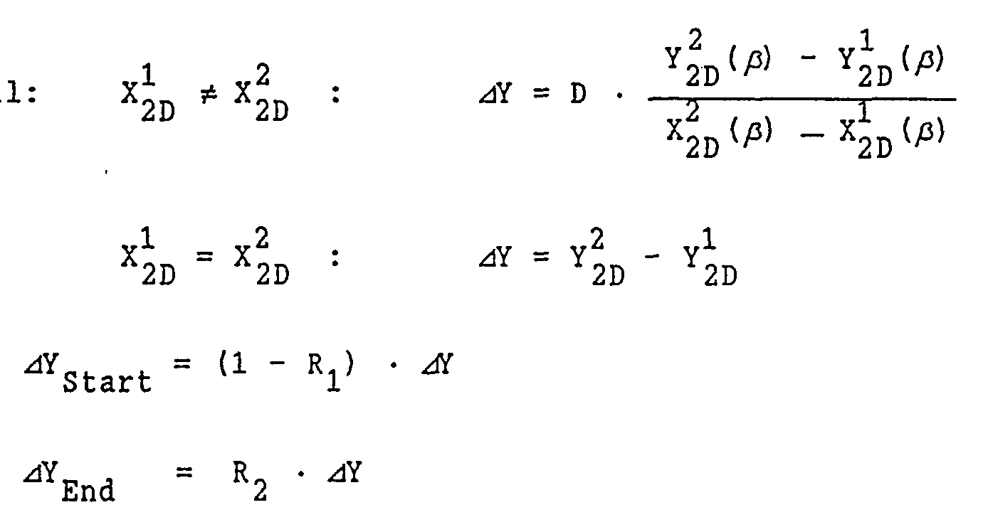
  • the length of the partial picture elements in the direction parallel to the cylindrical lenses is ge for the inner partial picture elements due to the slope of the line element give.
  • a separate calculation is required for the sub-picture elements at the beginning and at the end of the line element, since the positions of the start and end points relative to the cylindrical lenses must also be taken into account here.
  • the resolution i.e. the number of drawing files increases from the starting point to the ending point.
  • the method according to the invention is not limited to the representation of wire mesh models.
  • 1 to 3 show the positions of various Cartesian coordinate systems in relation to a cuboid object, to illustrate a sequence of coordinate transformations
  • FIG. 8 shows a diagram for explaining the assignment between individual cylindrical lenses of the lens array and associated zones of the image plane for a viewer at a finite distance from the image plane;
  • Fig. 9 is a planar image of a line element in a viewport of the image display medium
  • FIG. 10 shows a partial image belonging to the line element according to FIG. 9, which is calculated for a specific viewing direction and is rasterized in accordance with the lens array; 11 shows the appearance of the partial image according to FIG. 10 when it is viewed from the intended viewing direction through the lens array;
  • FIG. 14 shows the appearances of the partial images according to FIG. 13 when they are viewed from the respective associated viewing direction through the lens array;
  • 15 shows a wireframe model of an object to be displayed in the form of a cube
  • FIG. 16 shows a panorama diagram of the cube according to FIG. 15 calculated in original size for a cylindrical lens array with a period of 0.4 mm;
  • CAD programs allow the creation of drawing files from which the data about the drawing objects and the location of the viewer can be extracted in 3-dimensional vector form.
  • Drawing objects are made up of series of straight line elements and the location vectors for the start and end points of the
  • Line pieces are available for the location of the viewer and the target point of view as a data record from Tripein.
  • FIGS. 1 to 5 are to use the example of a cuboid to agree the conventional displacement, rotation and projection transformations, which change from a set of 3-dimensional location vectors (corner points) to one
  • RB, RH frame width, frame height of the view window
  • Non-linear functions d ( ⁇ ) can describe special lens properties or lens errors at this point
  • FIGS. 9 to 11 show the corresponding graphic structure (FIG. 10) and the final virtual image of this structure (FIG. 11) by means of an applied cylindrical lens array.
  • the view of the angle ⁇ in FIG. 9 corresponds to the
  • the line segments are mapped at the same angle ⁇ (FIG. 6) to the surface normal if and only if the horizontal period of the
  • Line structure coincides with the lens period and phase d ( ⁇ ) describes the position of the line focus to the angle ⁇ .
  • Figure 11 shows the image of the graphic structure through the
  • Lens array as appears only when viewed at an angle ⁇ to the array normal, perpendicular to the vertical and from a large distance.
  • Cylindrical lenses each cover the entire width of the individual lenses, so that there is a complete sequence of rectangles on the track of the original line (FIG. 8). If the period D of the lens array and the graphic structure are sufficiently short, the image from FIG. 9 again becomes the line, but with the virtual horizontal pixel size D.
  • FIG. 14 again shows the virtual image of the structure through the lens array.
  • the rectangles that correspond to the view with the marked lines in FIG. 13 are filled in again.
  • the other structures from FIG. 13 produce partially overlapping rectangles, the edges of which can be seen with ⁇ in accordance with their displacement.
  • FIGS. 16 to 19 show functional graphic structures in different scales for a cube (FIG. 15).
  • the target point A of the view is marked in FIG.
  • the typical curvilinear quadrilaterals from FIG. 13 can be found in the upper right area of FIG. 18 in a section of 15 times magnification.
  • stroke sequences according to FIG. 10 can be generated recursively in a subroutine.
  • This line data is stored digitally or output directly on a graphics-capable medium. Step sizes for the variation of the views:
  • the line sequences from FIG. 13 can, however, also shift horizontally over a plurality of lens widths D if the parallaxes between the extreme views of the line in FIG. 12 become larger. In each of the migrated lens areas, parts of the stroke sequences must be made
  • E is the greatest distance of the line element from the axis of rotation X '' in the system S '' '(Fig. 4).
  • the step size ⁇ ß is for each line element of the
  • Figures 15 to 19 show the graphic structure of a cube.
  • the vertical edge on the opposite side in FIG. 15 leads to a smaller number of vertical lines in the cutout in FIG. 18 than the front vertical edge in the cutout in FIG. 19. Because of the greater distance of the front edge to the view target point A and the larger parallax, there are more Views and correspondingly more lines were created than for the rear edge. In the area of the parallaxes of the cube edges, the swept cylindrical lenses are fully involved in the generation of the virtual image.
  • step 10 a program for calculating the panoramagram is called.
  • the user specifies from which source (input file) the data of the three-dimensional object should be taken and whether the calculated panorama diagram should be printed out immediately or saved in a file (output file).
  • source input file
  • the width and height of the image window and the position of the image (the view target point) within this window are defined.
  • step 12 it is checked whether the program can be executed with the parameters specified in step 10. If this is not the case, an error message is given in step 14 and the program is ended with step 16.
  • step 18 the first data are read from the source file 20 (input file).
  • the source file 20 contains data on the one hand that indicate the three-dimensional structure of one or more drawing objects, and on the other hand data that relate to the desired perspective representation of these objects.
  • step 22 it is checked whether the end of the source file has been reached. If this is not the case, a distinction is made in step 24 as to whether the data read relate to the perspective representation or to the geometry of the objects. Based on the perspective data, the transformation matrices T view and T2d mentioned above are created in step 26. The read data about the drawing objects are used in step 28 to generate lines which are defined by the start and end points of individual line elements. In step 30, the corresponding point sequences for the first object are stored in a buffer.
  • step 34 the line element is transformed into the view plane on the basis of the transformation matrices T view , T 2d and on the basis of the transformation matrix T ⁇ parallax for the respective value ⁇ , and thus a partial image of the line element for the initial Created angle ⁇ .
  • This partial image is then rasterized in step 36 according to the period of the lens array, ie the positions of the line-shaped partial image elements E according to FIG. 10 are calculated.
  • step 38 the calculated partial picture elements are either output to a graphic output medium, for example a printer, or are stored in a file 42 (output file) for later use.
  • Steps 34 and 36 are repeated recursively for angles ⁇ gradually increased by ⁇ until it is determined in step 44 that the angle ⁇ has reached the maximum value ⁇ parallax .
  • step 46 After all partial images of the line element have been created in this way, it is checked in step 46 whether the buffer filled in step 30 contains further line elements. If this is the case, steps 32 to 46 are repeated for the next line element. When the last line element of the object has been processed, step 46 returns to step 18 and the data for the next object are read. If different perspective data are stored in the source file 20 for the various objects, the transformation matrices can be changed in step 26 before the next object is processed.
  • step 22 If it is determined in step 22 that the end of the source file has been reached, the program is ended with step 16.

Landscapes

  • Engineering & Computer Science (AREA)
  • Physics & Mathematics (AREA)
  • Theoretical Computer Science (AREA)
  • Signal Processing (AREA)
  • Multimedia (AREA)
  • General Physics & Mathematics (AREA)
  • Software Systems (AREA)
  • Geometry (AREA)
  • Computer Graphics (AREA)
  • Computer Hardware Design (AREA)
  • General Engineering & Computer Science (AREA)
  • Stereoscopic And Panoramic Photography (AREA)
  • Testing, Inspecting, Measuring Of Stereoscopic Televisions And Televisions (AREA)
  • Transition And Organic Metals Composition Catalysts For Addition Polymerization (AREA)
  • Organic Low-Molecular-Weight Compounds And Preparation Thereof (AREA)
  • Processing Or Creating Images (AREA)
  • Image Processing (AREA)

Abstract

A process for producing spatial-effect images of three dimensional objects on a two-dimensional imaging medium on the parallax-panoramagram principle with the aid of a lens array in which a two-dimensional image of the object is calculated using stored data on the three-dimensional structure of the object for a given central direction of view, the positions of the partial image components (E) of the panoramagram in the lens array grid for several directions of view varying around the central direction are calculated for each image component of the computed image and the partial image components are displayed on the imaging medium at the calculated positions.

Description

VERFAHREN ZUM ERZEUGEN RAUMLICH WIRKENDER BILDER  METHOD FOR GENERATING SPATIAL ACTIVITIES
Die Erfindung betrifft ein Verfahren zum Erzeugen räumlich wirkender Bilder dreidimensionaler Objekte. The invention relates to a method for generating three-dimensional images of three-dimensional objects.
Es ist bekannt, da ß auch auf einem zweidimensionalen Bildwiedergabemedium, beispielsweise einem bedruckten Blatt Papier oder einem Bildschirm, der Eindruck räumlicher Tiefe hervorgerufen werden kann, indem auf dem Bildwiedergabemedium ein sogenanntes Parallax-Panoramagramm dargestellt wird, das dann durch ein unmittelbar vor der Bildebene angeordnetes Linsenarray betrachtet wird. Bei dem Parallax-Panoramagramm handelt es sich um eine ebene Darstellung des dreidimensionalen Objekts, die aus mehreren entsprechend dem Linsenraster ineinander verschachtelten Teilbildern besteht. Jedes Teilbild zeigt das Objekt aus einer etwas anderen AnSichtsrichtung, so daß durch die Gesamtheit der Teilbilder die parallaktische Verschiebung der Teile des Objekts bei Betrachtung aus unterschiedlichen Ansichtsrichtungen wiedergegeben wird. It is known that the impression of spatial depth can also be produced on a two-dimensional image reproduction medium, for example a printed sheet of paper or a screen, by displaying a so-called parallax panorama diagram on the image reproduction medium, which is then arranged by a immediately in front of the image plane Lens array is considered. The parallax panoramagram is a flat representation of the three-dimensional object, which consists of several partial images nested in one another in accordance with the lenticular grid. Each drawing shows the object from a slightly different viewing direction, so that the totality of the drawing shows the parallactic displacement of the parts of the object when viewed from different viewing directions.
Das Linsenarray dient dazu, die Teilbilder optisch voneinander zu trennen, so daß bei Betrachtung aus einer bestimmten Ansichtsrichtung jeweils nur das zu dieser Ansichtsrichtung gehörende Teilbild erkennbar ist. Hierzu wird das Linsenarray so vor dem Panoramagramm angeordnet, daß die Brennebene der Linsen im wesentlichen mit der Bildebene zusammenfällt. Das von einem einzelnen Punkt in der Bildebene ausgehende Licht wird dann durch die Linsen in ein im wesentlichen paralleles Strahlenbündel gebrochen, das mit der Bildnormalen einen bestimmten Winkel bildet. Ein virtuelles Bild dieses Punktes ist deshalb nur dann erkennbar, wenn das Panoramagramm unter diesem Winkel betrachtet wird. Der Winkel zwischen der Ansichtsrichtung und der Bildnormalen ist nach den Gesetzen der geometrischen Optik durch den Abstand zwischen dem betrachteten Punkt und der optischen Achse der zugehörigen Linse bestimmt. Die gewünschte Zuordnung zwischen den Teilbildern und den Ansichtsrichtungen läßt sich somit dadurch erreichen, daß die Teilbildelemente in geeigneten Positionen in bezug auf das Linsenraster angeordnet werden. The lens array is used to optically separate the partial images from one another, so that when viewed from a particular viewing direction, only the partial image belonging to this viewing direction can be seen. For this purpose, the lens array is arranged in front of the panoramagram in such a way that the focal plane of the lenses essentially coincides with the image plane. The light emanating from a single point in the image plane is then refracted by the lenses into an essentially parallel beam which forms a certain angle with the image normal. A virtual image of this point can therefore only be seen if the panoramagram is viewed from this angle. The angle between the view direction and the image normal is determined according to the laws of geometric optics by the distance between the point under consideration and the optical axis of the associated lens. The desired assignment between the partial images and the viewing directions can thus be achieved in that the partial image elements are arranged in suitable positions with respect to the lenticular grid.
In der Praxis wird zumeist mit einem Linsenarray aus vertikal verlaufenden Zylinderlinsen gearbeitet, und der Betrachtungswinkel wird in der Horizonta len variiert, so daß insbesondere die unterschiedlichen Parallaxen für das linke und das rechte Auge des Betrachters wiedergegeben werden und somit der Eindruck räumlicher Tiefe entsteht. Das herkömmliche Verfahren zur Herstellung solcher Parallax- Panoramagramme besteht darin, daß das darzustellende Objekt aus den verschiedenen Ansichtsrichtungen fotografiert wird, wobei das Linsenarray unmittelbar vor dem fotografischen Film angeordnet ist. Das Bild des Objekts wird somit bei jeder Einzelaufnahme durch die Zylinderlinsen in eine Schar paralleler Streifen fokussiert, die das betreffende Teilbild darstellen. In den Zwischenräumen zwischen diesen Streifen werden dann bei den Folgeaufnahmen die Teilbilder für die übrigen Ansichtsrichtungen erzeugt. Wenn der entwickelte Film später durch dasselbe oder ein gleiches Linsenarray betrachtet wird, sieht man ein räumliches Bild des Objekts. In practice, a lens array made of vertically extending cylindrical lenses is usually used, and the viewing angle is in the horizonta len varies, so that in particular the different parallaxes for the left and right eye of the viewer are reproduced and thus the impression of spatial depth is created. The conventional method for producing such parallax panoramagrams is that the object to be displayed is photographed from the different viewing directions, the lens array being arranged directly in front of the photographic film. The image of the object is thus focused by the cylindrical lenses into a family of parallel strips each time, which represent the relevant partial image. In the spaces between these strips, the partial images for the other viewing directions are then generated during the subsequent shots. If the developed film is later viewed through the same or an identical lens array, one sees a spatial image of the object.
In FUNKSCHAU 2/ 1987, Seiten 36 bis 39, ist vorgeschlagen worden, das oben beschriebene Prinzip für eine dreidimensionale Fernsehbildwiedergabe zu nutzen. Hierzu werden die mit Hilfe von Fernsehkameras erzeugten Teilbilder des Panoramagramms empfängerseitig mit mehreren Projektoren auf einen Großbildschirm projiziert, der mit einem Linsenarray versehen ist. In FUNKSCHAU 2/1987, pages 36 to 39, it has been proposed to use the principle described above for three-dimensional television picture reproduction. For this purpose, the partial images of the panoramagram generated with the aid of television cameras are projected on the receiver side with a plurality of projectors onto a large screen which is provided with a lens array.
Abgesehen von der oben erwähnten geplanten Anwendung im Bereich der Fernsehtechnik beschränken sich praktische Anwendungen der ParallaxPanoramagramme bisher im wesentlichen auf Postkarten und Scherzartikel. Apart from the planned application in the field of television technology mentioned above, practical applications of the parallax panorama diagrams have hitherto essentially been limited to postcards and joke articles.
Aufgabe der Erfindung ist es, ein Verfahren zum Erzeugen räumlicher Bilder anzugeben, durch das dem Techniker oder Designer die Interpretation von Konstruktionszeichnungen erleichtert wird, die beispielsweise mit Hilfe von CAD-Systemen erstellt wurden. The object of the invention is to provide a method for generating spatial images, by means of which the technician or designer is easier to interpret construction drawings which have been created, for example, with the aid of CAD systems.
Diese Aufgabe wird erfindungsgemäß mit den in den unabhängigen Patentansprüchen angegebenen Merkmalen gelöst. This object is achieved according to the invention with the features specified in the independent patent claims.
Der Grundgedanke der Erfindung besteht darin, daß anhand der beispielsweise mit Hilfe eines Rechners erzeugten und elektronisch gespeicherten Daten, die die dreidimensionale Struktur des Objekts festlegen, ein synthetisches Parallax-Panoramagramm berechnet wird, das dann auf einem hochauf lösenden Bildschirm dargestellt oder mit Hilfe eines hochauflösenden Druckers ausgedruckt, und durch ein entsprechendes Linsenarray betrachtet werden kann. Ein wesentlicher Vorteil dieses Verfahrens besteht darin, daß die elektronisch gespeicherten Daten direkt in ein räumliches Bild umgesetzt werden können, ohne daß hierzu ein reales dreidimensionales Modell angefertigt werden muß. Hierdurch besteht insbesondere auch die vorteilhafte Möglichkeit, verdeckte Strukturen im Inneren des Objekts dreidimensional darzustellen. The basic idea of the invention is that a synthetic parallax panorama diagram is calculated on the basis of the data generated, for example with the aid of a computer, and which defines the three-dimensional structure of the object, which is then displayed on a high displayed screen or printed out with the help of a high-resolution printer, and can be viewed through a corresponding lens array. A major advantage of this method is that the electronically stored data can be converted directly into a spatial image without the need for a real three-dimensional model. As a result, there is in particular the advantageous possibility of displaying hidden structures in the interior of the object in three dimensions.
Die Auflösung des dreidimensionalen Bildes ist durch das Raster des Linsenarrays bestimmt. Das Auflösungsvermögen des verwendeten Bildwiedergabemediums sollte ein Mehrfaches diese Auflösung betragen, damit eine entsprechende Anzahl von Teilbildern wiedergegeben werden kann. Mit heutigen Laserdruckern oder Tintenstrahldruckern ist jedoch eine Auflösung erreichbar, die für eine Darstellung dreidimensionaler Bilder mit einem hinreichend feinen Linsenraster ausreicht. Gewisse Einbußen bei der Bildauflösung werden dadurch mehr als wettgemacht, daß der Betrachter sich auf einen Blick einen unmittelbaren Eindruck von der räumlichen Struktur des Objekts verschaffen kann. Hierdurch wird die Interpretation von zusätzlich zur Verfügung gestellten zweidimensionalen Darstellungen wesentlich erleichtert. Dies gilt insbesondere für die perspektivische Darstellung von Objekten mit großer Detailfülle, da es der räumliche Eindruck dem Betrachter erleichtert, die verwirrende Linienvielfalt durch Unterscheidung von Vordergrund und Hintergrund zu strukturieren. The resolution of the three-dimensional image is determined by the grid of the lens array. The resolution of the image display medium used should be several times this resolution so that a corresponding number of sub-images can be displayed. With today's laser printers or inkjet printers, however, a resolution can be achieved which is sufficient for displaying three-dimensional images with a sufficiently fine lenticular grid. Certain losses in image resolution are more than made up for by the fact that the viewer can get an immediate impression of the spatial structure of the object at a glance. This considerably simplifies the interpretation of additionally provided two-dimensional representations. This applies in particular to the perspective representation of objects with great detail, since the spatial impression makes it easier for the viewer to structure the confusing variety of lines by differentiating the foreground and the background.
Das Verfahren läßt sich problemlos auch bei mehrfarbigen Darstellungen anwenden, wodurch die Übersichtlichkeit weiter erhöht wird. The method can also be used without problems with multicolored representations, which further increases the clarity.
Die Anzahl der synthetisch erzeugten Teilbilder beträgt mindestens zwei, entsprechend der Parallaxe zwischen dem linken und dem rechten Auge des Betrachters, kann jedoch auch wesentlich größer sein, so daß der Betrachter beim Bewegen des Kopfes eine quasi kontinuierliche Parallaxenverschiebung wahrnimmt. Bei einem Array aus Zylinderlinsen gilt dies nur für seitliche Kopfbewegungen, es kann jedoch auch ein Array aus gitter- oder wabenförmig angeordneten sphärischen Linsen verwendet werden, so daß sich auch unter schiedliche Parallaxen in der Vertikalen darstellen lassen. The number of synthetically generated partial images is at least two, corresponding to the parallax between the left and right eyes of the viewer, but can also be significantly larger so that the viewer perceives a quasi-continuous parallax shift when the head is moved. In the case of an array of cylindrical lenses, this only applies to lateral movements of the head, but an array of spherical lenses arranged in a lattice or honeycomb shape can also be used, so that even under display different parallaxes in the vertical.
Der Begriff "Teilbilder" ist in diesem Zusammenhang nicht so zu verstehen, daß ein Teilbild eine komplette Ansicht des gesamten dreidimensionalen Objekts repräsentieren muß, wenn dies aus einer bestimmten Ansichtsrichtung betrachtet wird, sondern der Begriff "Teilbild" bezeichnet vielmehr eine zweidimensionale Darstellung eines bestimmten Ausschnitts oder Elements des dreidimensionalen Objekts für eine bestimmte Ansichtsrichtung. Beispielweise wird ein dreidimensionales Linienelement des Objekts in mehrere zweidimensionale Linienelemente (Teilbilder) transformiert, die jeweils einer bestimmten Ansichtsrichtung entsprechen. Etwas allgemeiner formuliert wird jeder dreidimensionale Graphikvektor, der eine bestimmte Einzelheit des Objekts repräsentiert, in eine Anzahl zweidimensionaler Graphikvektoren transformiert, die jeweils einer anderen Ansichtsrichtung zugeordnet sind. In this context, the term “partial images” is not to be understood in such a way that a partial image must represent a complete view of the entire three-dimensional object when viewed from a certain viewing direction, but rather the term “partial image” denotes a two-dimensional representation of a specific section or element of the three-dimensional object for a certain view direction. For example, a three-dimensional line element of the object is transformed into several two-dimensional line elements (partial images), each of which corresponds to a certain viewing direction. More generally formulated, each three-dimensional graphic vector that represents a certain detail of the object is transformed into a number of two-dimensional graphic vectors, each of which is assigned to a different view direction.
Das Verfahren läßt sich mit geringem apparativen Aufwand realisieren, da zu seiner Durchführung außer einem Rechner und einem hochauflösenden Drucker, die in einem Konstruktionsbüro zumeist ohnehin verfügbar sind, lediglich das Linsenarray (z.B. eine Folie) und eine darauf abgestimmte Software benötigt werden. The method can be implemented with little outlay in terms of apparatus, since in addition to a computer and a high-resolution printer, which are usually already available in a design office, only the lens array (e.g. a film) and software that is matched to it are required.
Vorteilhafte Weiterbildungen und Ausgestaltungen des Verfahrens ergeben sich aus den Unteransprüchen. Advantageous further developments and refinements of the method result from the subclaims.
Ein besonderer Vorteil des Verfahren besteht darin, daß die Anzahl der verschiedenen Ansichtsrichtungen und damit die Anzahl der zu erzeugenden Teilbilder nicht für das gesamte Bild einheitlich festgelegt zu werden brauchen. Somit ist es möglich, für die Teile des Objekts, die eine große parallaktische Verschiebung erfahren, eine relativ große Anzahl von Teilbildern vorzusehen, so daß beim Ändern der Betrachtungsposition sprunghafte Übergänge über mehr als ein Pixel (mehr als eine Einzellinse) vermieden werden, während für Teile des Objekts, die sich in der Nähe des gedachten Drehzentrums (Ansichtszielpunktes) befinden und somit nur eine geringe parallaktisehe Verschiebung erfahren, nur eine kleinere Anzahl von Teilbildem erzeugt wird, so daß der Rechenaufwand minimiert wird und die Teilbildelemente mit dem Drucker sauber aufgelöst werden können. Für die Berechnung des Panoramagramms eines Objektes, das durch eine Menge von Vektoren in einem vorgegebenen dreidimensionalen Koordinatensystem definiert ist, geht man bevorzugt von der Vorstellung aus, daß der Betrachter sich an einem bestimmten Ort in endlicher Entfernung zu dem Objekt befindet und dann seine Betrachtungsposition leicht variiert, wobei der Blick stets auf einen bestimmten Ansichtszielpunkt gerichtet bleibt. Die zentrale Betrachtungsposition und der Ansichtszielpunkt werden nach Vorgaben des Benutzers in dem gegebenen Koordinatensystem festgelegt und bestimmen die zentrale Ansichtsrichtung. A particular advantage of the method is that the number of different viewing directions and thus the number of partial images to be generated need not be defined uniformly for the entire image. Thus, it is possible to provide a relatively large number of sub-images for the parts of the object which undergo a large parallactic shift, so that when changing the viewing position, abrupt transitions over more than one pixel (more than one single lens) are avoided, while for Parts of the object that are in the vicinity of the imaginary center of rotation (view target point) and thus experience only a small parallaktisehe shift, only a smaller number of sub-images is generated, so that the computational effort is minimized and the sub-picture elements can be resolved cleanly with the printer . For the calculation of the panoramagram of an object, which is defined by a set of vectors in a given three-dimensional coordinate system, it is preferable to start from the idea that the viewer is at a certain location at a finite distance from the object and then his viewing position is easy varies, whereby the gaze always remains on a certain view target point. The central viewing position and the view target point are determined according to the user's specifications in the given coordinate system and determine the central viewing direction.
Es ist zweckmäßig, durch eine Koordinatentransformation Tview auf ein kartesisches Koordinatensystem überzugehen, dessen Ursprung im Ansichtszielpunkt liegt und das so gedreht ist, daß eine Koordinatenachse, beispielweise die z-Achse, auf die zentrale Betrachtungsposition gerichtet ist und die beiden anderen Achsen in Richtung der Breite und Höhe des zweidimensionalen Bildwiedergabemediums verlaufen. Die Änderungen der Ansichtsrichtung entsprechend der Variation der Betrachtungsposition können dann durch Drehungen um einen kleinen Winkel β um die Hochachse des transformierten Koordinatensystems beschrieben werden. Die entsprechenden Drehtransformationen werden im folgenden mit Tβ Parallax bezeichnet. Durch ein weitere Transformation T2d werden die so erhaltenen dreidimensionalen Vektoren entsprechend der gewünschten Perspektive in die Ansichtsebene projiziert und in einem vorgegebenen Ansichtsfenster des Bildwiedergabemediums positioniert. It is useful to go through a coordinate transformation T view to a Cartesian coordinate system, the origin of which lies in the view target point and which is rotated such that a coordinate axis, for example the z-axis, is directed towards the central viewing position and the other two axes in the direction of the The width and height of the two-dimensional image display medium run. The changes in the viewing direction corresponding to the variation in the viewing position can then be described by rotations by a small angle β about the vertical axis of the transformed coordinate system. The corresponding rotational transformations are referred to below as T β parallax . By means of a further transformation T 2d , the three-dimensional vectors obtained in this way are projected into the view plane in accordance with the desired perspective and positioned in a predetermined view window of the image display medium.
Je nach Gestaltung des Linsenarrays ist es theoretisch denkbar, daß ein- und derselbe Punkt in der Bildebene durch mehrere benachbarte Linsen des Linsenarrays betrachtet werden kann (jeweils unter einem anderen Betrachtungswinkel). Im einfachsten Fall ist das Linsenarray jedoch so gestaltet, daß von jedem Bildpunkt nur durch eine einzige unmittelbar darüberliegende Linse ein virtuelles Bild erzeugt wird. Der maximale Abstand des Bildpunktes von der optischen Achse der zugehörigen Linse ist dann durch die Periode des Linsenrasters begrenzt. Damit ist auch der maximale Winkel zwischen der Betrachtungsrichtung und der Bildnormalen auf einen Wert ±βParallax begrenzt. Für die Drehtransformationen Tβ Parallax werden deshalb in diesem Fall nur Winkel innerhalb des Intervalls [-βParallax ,Parallax] herangezogen. In einem typischen Anwendungsfall kann man sich das darzustellende dreidimensionale Objekt beispielsweise als Drahtgittermodell aus geraden Linienelementen zusammengesetzt denken. Die Anfangs- und Endpunkte der Linienelemente sind dann durch die oben genannten Vektoren gegeben. In diesem Fall wird das Panoramagramm bevorzugt nacheinander für die einzelnen Linienelemente berechnet. Für jedes Linienelement wird zunächst die optimale Schrittweite Δβ für die Variation der Ansichtsrichtung innerhalb des oben genannten Intervalls bestimmt. Maßgebliche Parameter hierfür sind die Periode des Linsenrasters und das Ausmaß der parallaktischen Verschiebung, die das Linienelement bei der Änderung der Ansichtsrichtung erfährt. Diese parallaktische Verschiebung kann anhand des Abstands der Endpunkte des Linienelements vom Ansichtszielpunkt abgeschätzt werden. Depending on the design of the lens array, it is theoretically conceivable that one and the same point in the image plane can be viewed through several adjacent lenses of the lens array (each with a different viewing angle). In the simplest case, however, the lens array is designed in such a way that a virtual image is generated from each pixel by only a single lens directly above it. The maximum distance of the image point from the optical axis of the associated lens is then limited by the period of the lenticular grid. The maximum angle between the viewing direction and the image normal is thus also limited to a value ± β parallax . In this case, only angles within the interval [-β parallax, + β parallax ] are used for the rotational transformations T β parallax . In a typical application, the three-dimensional object to be displayed can be thought of as a wire frame model composed of straight line elements. The starting and ending points of the line elements are then given by the vectors mentioned above. In this case, the panoramagram is preferably calculated one after the other for the individual line elements. For each line element, the optimal step size Δβ for the variation of the viewing direction is first determined within the above-mentioned interval. Relevant parameters for this are the period of the lenticular grid and the extent of the parallactic displacement that the line element experiences when the viewing direction changes. This parallactic shift can be estimated from the distance of the end points of the line element from the view target point.
Je nach Lage des Linienelements im Raum zeigen die Endpunkte der ebenen Projektion im allgemeinen unterschiedlich große parallaktische Verschiebungen. Die ideale Schrittweite Δβ für die Ansichtsrichtung β, die zu Verschiebungen von exakt einer Periode D des Linsenarrays führt, variiert deshalb für die Orte entlang dem Linienelement und ist von seiner Lage im Raum und dem Winkel β der zentralen Ansichtsrichtung abhängig. Depending on the position of the line element in space, the end points of the flat projection generally show parallactic displacements of different sizes. The ideal step size Δβ for the viewing direction β, which leads to shifts of exactly one period D of the lens array, therefore varies for the locations along the line element and is dependent on its position in space and the angle β of the central viewing direction.
Zur Vereinfachung und Beschleunigung der Berechnungen ist es nützlich, die Schrittweite Δβ für das gesamte Linienelement einheitlich zu wählen. Die Schrittweite Δβ sollte dann so klein sein, daß die parallaktischen Verschiebungen von Teilbild zu Teilbild für alle Orte auf dem Linienelement maximal eine Linsenperiode D betragen. In diesem Fall wird die ebene Projektion des Linienelements zur Ansichtsrichtung β entsprechend der Periode D des Linsenarrays gerastert, das heißt, die Projektion des Linienelements wird in eine Anzahl von Teilstücken aufgeteilt, die den von dem Linienelement überstrichenen Zylinderlinsen entsprechen. Das zu einer bestimmten Ansichtsrichtung β gehörende Teilbild dieses Linienelements besteht dann aus einzelnen Pixeln oder Teilbildelementen in der Form dünner Linienstücke, die parallel zu den Zylinderlinsen verlaufen und in der hierzu senkrechten Richtung um den Abstand D gegeneinander versetzt sind. Die Positionen dieser Teilbildelemente relativ zu den Brennlinien der Zylinderlinsen können einheitlich aus dem zugehörigen Betrachtungswinkel β berechnet werden. Die Länge der Teilbildelemente in der Richtung parallel zu den Zylinderlinsen ist für die inneren Teilbildelemente durch die Steigung des Linienelements ge geben. Für die Teilbildelemente am Anfang und am Ende des Linienelements ist eine gesonderte Berechnung erforderlich, da hier auch die Positionen der Anfangs- und Endpunkte relativ zu den Zylinderlinsen zu berücksichtigen sind. To simplify and accelerate the calculations, it is useful to select the step size Δβ uniformly for the entire line element. The step size Δβ should then be so small that the parallactic shifts from field to field for all locations on the line element amount to a maximum of one lens period D. In this case, the plane projection of the line element to the viewing direction β is rasterized in accordance with the period D of the lens array, that is to say the projection of the line element is divided into a number of sections which correspond to the cylindrical lenses swept by the line element. The partial image of this line element belonging to a certain viewing direction β then consists of individual pixels or partial image elements in the form of thin line pieces which run parallel to the cylindrical lenses and are offset from one another by the distance D in the direction perpendicular thereto. The positions of these partial picture elements relative to the focal lines of the cylindrical lenses can be calculated uniformly from the associated viewing angle β. The length of the partial picture elements in the direction parallel to the cylindrical lenses is ge for the inner partial picture elements due to the slope of the line element give. A separate calculation is required for the sub-picture elements at the beginning and at the end of the line element, since the positions of the start and end points relative to the cylindrical lenses must also be taken into account here.
In einer alternativen Ausführungsform ist es auch möglich, zunächst das zu der zentralen Betrachtungsposition (β = 0) gehörende Linien element in eine Anzahl von Teilstücken aufzuteilen und dann die Schrittweite Δβ für jedes Teilstück gesondert zu berechnen. Hierdurch läßt sich beispielsweise erreichen, daß für ein Linienelement, das in dem dreidimensionalen Objekt in der Nähe des Ansichtszielpunktes beginnt und sich von dort in die Tiefe des Raumes erstreckt, die Auflösung, d.h. die Anzahl der Teilbilder, vom Anfangspunkt zum Endpunkt hin zunimmt. Wenn man eine Betrachtungsposition in endlicher Entfernung zur Bildebene annimmt, so daß die Sichtstrahlen vom Betrachter zu den Endpunkten des Linienelements divergent sind, so sind im allgemeinen die korrekten Positionen der Teilbilder relativ zum Linsenarray auch von der Dicke des Linsenarrays abhängig. Dies läßt sich dadurch berücksichtigen, daß anstelle der tatsächlichen Periode des Linsenarrays eine scheinbare Periode D zugrundegelegt wird, die entsprechend dem Verhältnis zwischen Betrachtungsabstand und Dicke des Linsenarrays korrigiert ist. In an alternative embodiment, it is also possible to first divide the line element belonging to the central viewing position (β = 0) into a number of sections and then to calculate the step size Δβ separately for each section. In this way it can be achieved, for example, that for a line element that begins in the three-dimensional object in the vicinity of the view target point and extends from there into the depth of the space, the resolution, i.e. the number of drawing files increases from the starting point to the ending point. If one assumes a viewing position at a finite distance from the image plane, so that the sight rays from the viewer to the end points of the line element are divergent, the correct positions of the partial images relative to the lens array are generally also dependent on the thickness of the lens array. This can be taken into account by using an apparent period D instead of the actual period of the lens array, which is corrected according to the relationship between the viewing distance and the thickness of the lens array.
Das erfindungsgemäße Verfahren ist nicht auf die Darstellung von Drähtgittermodellen beschränkt. Es ist beispielsweise auch möglich, naturgetreue räumliche Bilder von nicht durchsichtigen Objekten zu erzeugen, indem für jede Ansichtsrichtung jeweils nur die Teilbilder der Linien erzeugt werden, die aus dieser Ansichtsrichtung sichtbar sind. Ebenso ist es möglich, Objekte mit farbigen Oberflächen darzustellen, indem für die Oberflächen, die in der jeweiligen Ansichtsrichtung sichtbar sind, Teilbilder in der Form paralleler Linien im Raster des Linsenarrays erzeugt werden. Im folgenden wird ein Ausführungsbeispiel der Erfindung anhand der Zeichnung näher erläutert. eigen: The method according to the invention is not limited to the representation of wire mesh models. For example, it is also possible to produce lifelike spatial images of non-transparent objects by only generating the partial images of the lines that are visible from this viewing direction for each viewing direction. It is also possible to display objects with colored surfaces by generating partial images in the form of parallel lines in the grid of the lens array for the surfaces that are visible in the respective viewing direction. An exemplary embodiment of the invention is explained in more detail below with reference to the drawing. own:
Fig. 1 bis 3 die Lagen verschiedener kartesischer Koordinatensysteme in bezug auf ein quaderförmiges Objekt, zur Illustration einer Folge von Koordinatentransformationen; 1 to 3 show the positions of various Cartesian coordinate systems in relation to a cuboid object, to illustrate a sequence of coordinate transformations;
Fig. 4 Koordinatentransformationen, die die Variation der Ansichtsrichtung (d. h., des Ortes des Betrachters) beschreiben; 4 shows coordinate transformations describing the variation of the viewing direction (i.e., the location of the viewer);
Fig. 5 zweidimensionale Abbilder des quaderförmigen Objekts nach Figuren 1 bis 4 für unterschiedliche Ansichtsrichtungen entsprechend Figur 4; Fig. 6 u. 7 Skizzen zur Erläuterung der Abbildungseigenschaften eines Linsenarrays; 5 two-dimensional images of the cuboid object according to FIGS. 1 to 4 for different viewing directions corresponding to FIG. 4; Fig. 6 u. 7 sketches to explain the imaging properties of a lens array;
Fig. 8 ein Diagramm zur Erläuterung der Zuordnung zwischen einzelnen Zylinderlinsen des Linsenarrays und zugehörigen Zonen der Bildebene für einen Betrachter in endlicher Entfernung zu der Bildebene; 8 shows a diagram for explaining the assignment between individual cylindrical lenses of the lens array and associated zones of the image plane for a viewer at a finite distance from the image plane;
Fig. 9 ein ebenes Bild eines Linienelements in einem Ansichtsfenster des Bildwiedergabemediums; Fig. 9 is a planar image of a line element in a viewport of the image display medium;
Fig. 10 ein zu dem Linienelement nach Figur 9 gehörendes Teilbild, das für eine bestimmte Ansichtsrichtung berechnet und entsprechend dem Linsenarray gerastert ist; Fig. 11 das Erscheinungsbild des Teilbildes nach Figur 10, wenn es aus der vorgesehenen Betrachtungsrichtung durch das Linsenarray betrachtet wird; 10 shows a partial image belonging to the line element according to FIG. 9, which is calculated for a specific viewing direction and is rasterized in accordance with the lens array; 11 shows the appearance of the partial image according to FIG. 10 when it is viewed from the intended viewing direction through the lens array;
Fig. 12 die Extremlagen des Linienelements nach Figur 9 für eine maximale Variation der Ansichtsrichtung; Fig. 13 Teilbilder des Linienelements entsprechend Figur 10 für eine Vielzahl diskreter Ansichtsrichtungen; 12 shows the extreme positions of the line element according to FIG. 9 for a maximum variation of the viewing direction; 13 partial images of the line element corresponding to FIG. 10 for a multiplicity of discrete viewing directions;
Fig. 14 die Erscheinungsbilder der Teilbilder nach Figur 13, wenn sie aus der jeweils zugehörigen Ansichtsrichtung durch das Linsenarray betrachtet werden; 14 shows the appearances of the partial images according to FIG. 13 when they are viewed from the respective associated viewing direction through the lens array;
Fig. 15 ein Drahtgittermodell eines darzustellenden Objektes in der Form eines Würfels; 15 shows a wireframe model of an object to be displayed in the form of a cube;
Fig. 16 ein für ein Zylinderlinsen-Array mit einer Periode von 0,4 mm berechnetes Panoramagramm des Würfels nach Figur 15 in Originalgröße; 16 shows a panorama diagram of the cube according to FIG. 15 calculated in original size for a cylindrical lens array with a period of 0.4 mm;
Fig. 17 bis 19 vergrößerte Darstellungen des Panoramagramms nach 17 to 19 are enlarged representations of the panoramagram according to
Figur 16; und  Figure 16; and
Fig. 20 ein Flußdiagramm zur Erläuterung des erfindungsgemäßen Verfahrens. 20 shows a flow chart to explain the method according to the invention.
Transformationen zur Erzeugung einer konventionellen Ansicht: Transformations to create a conventional view:
Die Berechnung der graphischen Strukturen zum 3-D-Bild setzt The calculation of the graphic structures for the 3-D image sets
Zeichnungsobjekte voraus, deren geometrischen Daten in vektorieller Form verfügbar gemacht werden können. Fast alle marktüblichen  Drawing objects ahead, whose geometric data can be made available in vector form. Almost all common ones
CAD-Programme lassen die Erzeugung von Zeichnungsdateien zu, aus denen die Daten über die Zeichnungsobjekte und der Standort des Betrachters in 3-dimensional vektorieller Form extrahiert werden können.  CAD programs allow the creation of drawing files from which the data about the drawing objects and the location of the viewer can be extracted in 3-dimensional vector form.
Die nachfolgenden Rechnungen setzen konkret voraus, daß alle  The following calculations specifically assume that all
Zeichnungsobjekte aus Serien von geraden Linienelementen aufgebaut sind und die Ortsvektoren für Anfangs- und Endpunkte der Drawing objects are made up of series of straight line elements and the location vectors for the start and end points of the
Linienstücke, für den Standort des Betrachters und den Zielpunkt der Blickrichtung als Datensatz aus Tripein vorliegen. Line pieces are available for the location of the viewer and the target point of view as a data record from Tripein.
Die Generierung der graphischen Struktur in der Ebene erfordert zuerst eine Ansicht des Zeichnungsobjektes vom Ort des Betrachters und mit dem beabsichtigten Bildausschnitt. Die Figuren 1 bis 5 sollen am Beispiel eines Quaders die konventionellen Verschiebe-, Dreh- und Projektionstransformationen vereinbaren, die von einem Satz 3-dimensionaler Ortsvektoren (Eckpunkte) zu einer The generation of the graphic structure in the plane first requires a view of the drawing object from the location of the viewer and with the intended image section. FIGS. 1 to 5 are to use the example of a cuboid to agree the conventional displacement, rotation and projection transformations, which change from a set of 3-dimensional location vectors (corner points) to one
2-dimensionalen Ansichtsprojektion (Fig. 5) führen. 2-dimensional view projection (Fig. 5).
Figur 1: Figure 1:
Übergang vom System S(X,Y,Z) in das System S'(X',Y',Z') durch Verschiebung des Koordinatenursprungs in den  Transition from the S (X, Y, Z) system to the S '(X', Y ', Z') system by moving the origin of the coordinate system to the
Ansichtszielpunkt
Figure imgf000012_0002
des Betrachters am Ort :
View target point
Figure imgf000012_0002
of the viewer at the location:
Figure imgf000012_0003
Figure imgf000012_0001
für alle Vektoren
Figure imgf000012_0004
Figure imgf000012_0001
for all vectors
Figure imgf000012_0004
Figur 2: Figure 2:
Übergang vom System S'(X',Y',Z') nach S"(X'',Y",Z'')  Transition from system S '(X', Y ', Z') to S "(X '', Y", Z '')
durch positive Drehung der X'- und Y'-Achse um die Z'-Achse um den Winkel φ:  by positive rotation of the X'- and Y'-axis around the Z'-axis by the angle φ:
Die entsprechende Drehung der Ortvektoren:
Figure imgf000012_0005
Bestimmung von φ aus den Komponenten von
The corresponding rotation of the location vectors:
Figure imgf000012_0005
Determination of φ from the components of
Figure imgf000013_0006
Figure imgf000013_0001
Figure imgf000013_0006
Figure imgf000013_0001
Figur 3:  Figure 3:
Übergang von S "(X'',Y",Z'') nach S"'(X"',Y"',Z'") durch positive Drehung der X''- und Z''-Achse um die Y''-Achse um den Winkel θ:  Transition from S "(X '', Y", Z '') to S "'(X"', Y "', Z'") by positive rotation of the X '' and Z '' axes around the Y '' Axis around the angle θ:
Die entsprechende Drehung der Ortsvektoren:
Figure imgf000013_0002
The corresponding rotation of the location vectors:
Figure imgf000013_0002
Bestimmung von θ aus den Komponenten von
Figure imgf000013_0003
Figure imgf000013_0004
Determination of θ from the components of
Figure imgf000013_0003
Figure imgf000013_0004
Die bisherigen Transformationen überführen die Vektoren in das System S''', in dem die Ansichtsrichtung parallel zur Z'''-Achse verläuft; im Folgenden zusammengefaßt als:
Figure imgf000013_0005
The previous transformations transfer the vectors into the system S ''', in which the viewing direction runs parallel to the Z'''axis; summarized below as:
Figure imgf000013_0005
Figur 4:  Figure 4:
'Perspektivische' Drehung in S'''(X''',Y"',Z'") um β:  'Perspective' rotation in S '' '(X' '', Y "', Z'") by β:
(z. B. zur Erzeugung der Ansichten von Orten zwischen dem rechten und linken Auge des fiktiven Betrachters)
Figure imgf000013_0007
ß aus dem Intervall [- βParal l ax, βParallax]
(e.g. to generate views of locations between the right and left eyes of the fictional viewer)
Figure imgf000013_0007
ß from the interval [- β Paral l ax , β Parallax ]
βParallax : Maximaler Winkel, in den die Bildstrahlen von β Parallax : Maximum angle at which the image rays from
graphischen Strukturen an den Rändern der Linsen abgelenkt werden können (Fig. 7);  graphic structures at the edges of the lenses can be deflected (Fig. 7);
eine Eigenschaft der Linsen.  a property of the lenses.
Figur 5: Figure 5:
Proj ektion der 3-dim. Vektoren in die Ebene der Ansicht :
Figure imgf000014_0002
Projection of the 3-dim. Vectors in the plane of the view:
Figure imgf000014_0002
RB, RH : Rahmenbreite, Rahmenhöhe des Ansichtsfensters, RB, RH: frame width, frame height of the view window,
Xzv, Yzv: Horizontale Verschiebung, vertikale Verschiebung X zv , Y zv : horizontal shift, vertical shift
des Fensterzentrums bezogen auf die Projektion des Ursprungs von S'''.  of the window center related to the projection of the origin of S '' '.
Andere Perspektiven als die hier gezeigte Normalperspektive erfordern nur an dieser Stelle andere Formen für T2D. Die weiteren Beschreibungen bleiben auch dann gültig. Perspectives other than the normal perspective shown here only require different forms for T 2D at this point. The other descriptions remain valid even then.
Abbildunqseigenschaften des Linsenarrays: Imaging properties of the lens array:
Zur Vereinfachung der Beschreibung sollen die optischen To simplify the description, the optical
Eigenschaften des Linsenarrays (Fig. 6) derart idealisiert sein, daß für alle Bildpunkte in den Brennebenen und deren Abbildung die Beziehung
Figure imgf000014_0001
Properties of the lens array (Fig. 6) should be idealized such that the relationship for all pixels in the focal planes and their imaging
Figure imgf000014_0001
d : Abstand des Punktes von der Linsenmitte,  d: distance of the point from the center of the lens,
ß : Ablenkung des Bildstrahles von der Bildnormalen, gültig ist. Nicht-lineare Funktionen d(β) können an dieser Stelle spezielle Linseneigenschaften beschreiben oder Linsenfehler  ß: deflection of the image beam from the image normal, is valid. Non-linear functions d (β) can describe special lens properties or lens errors at this point
berücksichtigen und sind mit den nachfolgenden Herleitungen take into account and are with the following derivations
verträglich. Funktionsweise der Bilderzeugung und der 3-D-Bildwirkunq: compatible. Functionality of the image generation and the 3-D image effect:
Die Figuren 9 bis 11 zeigen für den exemplarischen Fall eines geraden Linienelements in der Ebene der Ansicht (Fig. 9) die entsprechende graphische Struktur (Fig. 10) und das endgültige virtuelle Bild dieser Struktur (Fig. 11) durch ein aufgebrachtes Zylinderlinsenarray. For the exemplary case of a straight line element in the plane of the view (FIG. 9), FIGS. 9 to 11 show the corresponding graphic structure (FIG. 10) and the final virtual image of this structure (FIG. 11) by means of an applied cylindrical lens array.
Die Ansicht zum Winkel ß in Figur 9 korrespondiert mit den The view of the angle β in FIG. 9 corresponds to the
senkrechten Linienelementen in Figur 10 (dicke Linien). Die dicken Linienstücke in Figur 10 befinden sich dort, wo jede Zylinderlinse einen Strichfokus zum Ablenkwinkel ß bildet. Die Regionen der Zylinderlinsen in Figur 10 sind durch senkrechte Linien (Periode D) markiert.  vertical line elements in Figure 10 (thick lines). The thick line pieces in FIG. 10 are located where each cylindrical lens forms a line focus to the deflection angle β. The regions of the cylindrical lenses in Figure 10 are marked by vertical lines (period D).
Die Linienstücke werden genau dann in gleiche Winkel ß (Fig. 6) zur Flächennormalen abgebildet, wenn die horizontale Periode der  The line segments are mapped at the same angle β (FIG. 6) to the surface normal if and only if the horizontal period of the
Linienstruktur mit der Linsenperiode übereinstimmt und die Phase d(β) die Position des Strichfokus zum Winkel β beschreibt. Line structure coincides with the lens period and phase d (β) describes the position of the line focus to the angle β.
Figur 11 zeigt das Bild der graphischen Struktur durch das Figure 11 shows the image of the graphic structure through the
Linsenarray, wie es nur bei Betrachtung in. Winkel ß zurArraynormalen, senkrecht zur Vertikalen und aus großem Abstand erscheint. Die Helligkeitmodulationen in den Strichfoki der Lens array, as appears only when viewed at an angle β to the array normal, perpendicular to the vertical and from a large distance. The brightness modulations in the line focus
Zylinderlinsen erfüllen jeweils die ganze Breite der einzelnen Linsen, so daß eine lückenlose Folge von Rechtecken auf der Spur der ursprünglichen Linie (Fig. 8) entsteht. Bei hinreichend kleiner Periode D des Linsenarrays und der graphischen Struktur wird aus diesem Bild wieder die Linie aus Figur 9, jedoch mit der virtuellen horizontalen Pixelgröße D. Cylindrical lenses each cover the entire width of the individual lenses, so that there is a complete sequence of rectangles on the track of the original line (FIG. 8). If the period D of the lens array and the graphic structure are sufficiently short, the image from FIG. 9 again becomes the line, but with the virtual horizontal pixel size D.
Den verschiedenen Bereichen der Strichfoki zu unterschiedlichen Winkeln ß können unterschiedliche Bilder aufmoduliert werden. Durch die Wahl eines speziellen Betrachterstandpunktes im Winkel ß zur Bildnormalen besteht die Möglichkeit, die einzelnen Bilder wieder zu trennen. Der Eindruck einer 3-dimensionalen Ansicht mit Parallaxe entsteht, wenn die Bilder unterschiedliche Ansichten des Different images can be modulated onto the different areas of the line focus at different angles β. By choosing a special viewer point of view at an angle β to the image normal, it is possible to separate the individual images again. The impression of a 3-dimensional view with parallax arises when the images have different views of the
3-dimensionalen Objektes zeigen. Das Bild zum Betrachterwinkel ß muß dabei der Ansicht bei Wanderung um die Hochachse des Objektes um den Winkel -ß entsprechen. Bei einem realen Betrachterstandort B in endlicher Entfernung L vor dem Linsenarray muß das Bündel paralleler Strahlen (Fig. 6) durch solche ersetzt werden, die sich am Ort des Betrachters schneiden (Fig. 8). Das ist durch eine vergrößerte Periode der graphischen Struktur D relativ zur Periode DZyl des Linsenarrays zu erreichen. In Fig. 8 ist das Verhältnis 1/L stark überhöht. Die vergrößerte Periode D der graphischen Struktur folgt aus Geometrieüberlegungen zu:
Figure imgf000016_0002
Show 3-dimensional object. The image for the observer angle ß must correspond to the view when moving around the vertical axis of the object by the angle ß. At a real observer location B at a finite distance L in front of the lens array, the bundle of parallel rays (FIG. 6) must be replaced by those that intersect at the observer's location (FIG. 8). This can be achieved by an enlarged period of the graphic structure D relative to the period D cyl of the lens array. In Fig. 8 the ratio 1 / L is greatly exaggerated. The enlarged period D of the graphical structure follows from geometry considerations:
Figure imgf000016_0002
Werden für mehrere äquidistante Winkel zwischen den extremen  Be for several equidistant angles between the extreme
Ansichten
Figure imgf000016_0001
Views
Figure imgf000016_0001
der Linie (Fig. 12) die Strichfolgen analog zu Figur 10 erzeugt, so entstehen komplexe graphische Strukturen wie in Figur 13. Zur Verdeutlichung der korrelierten Bereiche sind nur die Striche einer Ansicht ß ausgefüllt. Figur 14 zeigt wieder das virtuelle Bild der Struktur durch das Linsenarray. Die Rechtecke, die der Ansicht mit den markierten Strichen in Figur 13 entsprechen, sind wieder ausgefüllt. Die übrigen Strukturen aus Figur 13 erzeugen teilweise überlappende Rechtecke, deren Ränder entsprechend ihrer Verschiebung mit ß zu sehen sind. If the line (FIG. 12) generates the stroke sequences analogously to FIG. 10, complex graphic structures are created as in FIG. FIG. 14 again shows the virtual image of the structure through the lens array. The rectangles that correspond to the view with the marked lines in FIG. 13 are filled in again. The other structures from FIG. 13 produce partially overlapping rectangles, the edges of which can be seen with β in accordance with their displacement.
Die Figuren 16 bis 19 zeigen funktionstüchtige graphische Strukturen in verschiedenen Maßstäben für einen Würfel (Fig. 15). In Figur 15 ist der Zielpunkt A der Ansicht markiert. Die Struktur im Maßstab 1:1 (Fig. 16) wurde für ein Linsenarray mit DZyl = 0.4 mm berechnet. Die typischen krummlinigen Vierecke aus Figur 13 finden sich im oberen rechten Bereich der Figur 18 im Ausschnitt der 15-fachen Vergrößerung wieder. Rechnungen zum 3-D-Bild eines Linienelementes im Raum: FIGS. 16 to 19 show functional graphic structures in different scales for a cube (FIG. 15). The target point A of the view is marked in FIG. The structure on a scale of 1: 1 (FIG. 16) was calculated for a lens array with D cyl = 0.4 mm. The typical curvilinear quadrilaterals from FIG. 13 can be found in the upper right area of FIG. 18 in a section of 15 times magnification. Calculations for the 3-D image of a line element in space:
Situation: Linienelement von nach im 3-D-Raum,Situation: line element from to in 3-D space,
Figure imgf000017_0008
im Winkel ß zur zentralen Ansicht betrachtet.  viewed at an angle ß to the central view.
Mit den Koordinaten in der Ebene der Ansicht:
Figure imgf000017_0001
With the coordinates in the plane of the view:
Figure imgf000017_0001
und mit der Ordnung von und derart, daß sei: and with the order of and such that
Figure imgf000017_0002
Figure imgf000017_0003
Figure imgf000017_0004
Figure imgf000017_0002
Figure imgf000017_0003
Figure imgf000017_0004
Figure imgf000017_0005
Die Größen der Strichfolge nach Figur 10:  The sizes of the stroke order according to Figure 10:
Figure imgf000017_0006
Fall: Case:
Figure imgf000017_0007
Mit diesen Größen können Strichfolgen nach Figur 10 in einem Unterprogramm rekursiv erzeugt werden. Diese Liniendaten werden digital gespeichert oder auf einem graphikfähigen Medium direkt ausgegeben. Schrittweiten für die Variation der Ansichten: With these quantities, stroke sequences according to FIG. 10 can be generated recursively in a subroutine. This line data is stored digitally or output directly on a graphics-capable medium. Step sizes for the variation of the views:
In Figur 12 bleiben die Endpunkte der Linie für alle Ansichten ß aus dem Bereich -ßPar allax bis ßPar allax unterhalb der jeweiligen In FIG. 12, the end points of the line remain below the respective for all views β from the range -ß Par allax to ß Par allax
Zylinderlinse. Im virtuellen Bild mit Linsenarray (Fig. 14) treten entsprechend nur vertikale Verschiebungen der Pixel auf.  Cylindrical lens. Accordingly, only vertical shifts of the pixels occur in the virtual image with a lens array (FIG. 14).
Die Strichfolgen aus Figur 13 können sich jedoch auch horizontal über mehrere Linsenbreiten D verlagern, wenn die Parallaxen zwischen den extremen Ansichten der Linie in Figur 12 größer werden. In jedem der durchwanderten Linsenbereiche müssen Teile der Strichfolgen aus The line sequences from FIG. 13 can, however, also shift horizontally over a plurality of lens widths D if the parallaxes between the extreme views of the line in FIG. 12 become larger. In each of the migrated lens areas, parts of the stroke sequences must be made
Figur 10 vorhanden sein, damit die Bildelemente in der virtuellenFigure 10 be present so that the picture elements in the virtual
Ansicht durch das Linsenarray stetig mit ß von Linse zu Linse wechseln. Change view through lens array with ß from lens to lens.
Diese Forderung macht eine Beschränkung der Schrittweiten für ß notwendig.  This requirement makes it necessary to limit the step sizes for ß.
Eine obere Schranke für die Schrittweite von ß und für ein An upper bound for the step size of ß and for a
Linienelement von nachLine element from to
Figure imgf000018_0001
Figure imgf000018_0002
Figure imgf000018_0001
Figure imgf000018_0002
ist : mit:
Figure imgf000018_0003
is with:
Figure imgf000018_0003
E ist der größte Abstand des Linienelementes von der Drehachse X'' im System S''' (Fig. 4).  E is the greatest distance of the line element from the axis of rotation X '' in the system S '' '(Fig. 4).
Die Schrittweite Δß wird für jedes Linienelement des The step size Δß is for each line element of the
Zeichnungsobjektes individuell berechnet und variiert mit dem  Drawing object individually calculated and varies with that
Abstand vom Ansichtzielpunkt A. Mit der Schrittweite Δß variiert auch die Anzahl der Ansichten ß im Intervall von -ßPar allax bisßPar allax. Der graphischen Struktur insgesamt kann deshalb keine einheitliche Anzahl von Einzelansichten zugeordnet werden. Figuren 15 bis 19 zeigen die graphische Struktur eines Würfels. Die senkrechte Kante auf der abgewandten Seite in Figur 15 führt zu einer geringeren Anzahl senkrechter Linien im Ausschnitt Fig. 18, als die vordere senkrechte Kante in Ausschnitt Fig. 19. Aufgrund der größeren Entfernung der vorderen Kante zum Ansichtszielpunkt A und der größeren Parallaxe sind mehr Ansichten und entsprechend mehr Linien erzeugt worden als für die hintere Kante. Im Bereich der Parallaxen der Würfelkanten werden die überstrichenen Zylinderlinsen lückenlos an der Erzeugung des virtuellen Bildes beteiligt. Distance from view target point A. With the step size Δß, the number of views ß also varies in the interval from -ß par allax to ß par allax . Therefore, the graphic structure as a whole cannot be assigned a uniform number of individual views. Figures 15 to 19 show the graphic structure of a cube. The vertical edge on the opposite side in FIG. 15 leads to a smaller number of vertical lines in the cutout in FIG. 18 than the front vertical edge in the cutout in FIG. 19. Because of the greater distance of the front edge to the view target point A and the larger parallax, there are more Views and correspondingly more lines were created than for the rear edge. In the area of the parallaxes of the cube edges, the swept cylindrical lenses are fully involved in the generation of the virtual image.
Das Flußdiagramm in Figur 20 verwendet die vorausgehenden The flow chart in Figure 20 uses the foregoing
Herleitungen und Bezeichnungen und beschreibt das Programm zur Erzeugung der graphischen Strukturen für die 3-D-Bilder. Derivation and designation and describes the program for creating the graphic structures for the 3-D images.
In Schritt 10 wird ein Programm zur Berechnung des Panoramagramms aufgerufen. Dabei wird durch den Benutzer spezifiziert, aus welcher Quelle (input file) die Daten des dreidimensionalen Objekts übernommen werden sollen, und ob das berechnete Panoramagramm unmittelbar ausgedruckt oder in einer Datei (output file) gespeichert werden soll. Außerdem werden die Breite und Höhe des Bildfensters sowie die Position des Bildes (des Ansichtszielpunktes) innerhalb dieses Fensters festgelegt. In step 10, a program for calculating the panoramagram is called. The user specifies from which source (input file) the data of the three-dimensional object should be taken and whether the calculated panorama diagram should be printed out immediately or saved in a file (output file). In addition, the width and height of the image window and the position of the image (the view target point) within this window are defined.
In Schritt 12 wird überprüft, ob das Programm mit den in Schritt 10 spezifizierten Parametern ausgeführt werden kann. Falls dies nicht der Fall ist, erfolgt in Schritt 14 eine Fehlermeldung, und das Programm wird mit Schritt 16 beendet. In step 12 it is checked whether the program can be executed with the parameters specified in step 10. If this is not the case, an error message is given in step 14 and the program is ended with step 16.
Wenn in Schritt 12 festgestellt wurde, daß die eingegebenen Parameter für einen Programmlauf geeignet sind, so werden in Schritt 18 die ersten Daten aus der Quellendatei 20 (input file) gelesen. Die Quellendatei 20 enthält einerseits Daten, die die dreidimensionale Struktur eines oder mehrerer Zeichnungs-Objekte angeben, und andererseits Daten, die sich auf die gewünschte perspektivische Darstellung dieser Objekte beziehen. If it was determined in step 12 that the entered parameters are suitable for a program run, then in step 18 the first data are read from the source file 20 (input file). The source file 20 contains data on the one hand that indicate the three-dimensional structure of one or more drawing objects, and on the other hand data that relate to the desired perspective representation of these objects.
In Schritt 22 wird überprüft, ob das Ende der Quellendatei erreicht ist. Wenn dies nicht der Fall ist, wird in Schritt 24 unterschieden, ob die gelesenen Daten sich auf die perspektivische Darstellung oder auf die Geometrie der Objekte beziehen. Anhand der Daten zur Perspektive werden in Schritt 26 die oben erwähnten Transformationsmatrizen Tview und T2d erstellt. Die gelesenen Daten über die Zeichnungs-Objekte dienen in Schritt 28 zur Erzeugung von Linienzügen, die durch die Anfangs- und Endpunkte einzelner Linienelemente definiert sind. In Schritt 30 werden die entsprechenden Punktfolgen für das erste Objekt in einem Puffer gespeichert. In step 22 it is checked whether the end of the source file has been reached. If this is not the case, a distinction is made in step 24 as to whether the data read relate to the perspective representation or to the geometry of the objects. Based on the perspective data, the transformation matrices T view and T2d mentioned above are created in step 26. The read data about the drawing objects are used in step 28 to generate lines which are defined by the start and end points of individual line elements. In step 30, the corresponding point sequences for the first object are stored in a buffer.
Die Koordinaten der Anfangs- und Endpunkte P 1 , P2 der Linienelemente werden in Schritt 32 aus dem Puffer gelesen, die Schrittweite Δβ für das betreffende Linienelement wird bestimmt, und der Betrachtungswinkel β wird auf den Anfangswert -βParallax gesetzt. In Schritt 34 wird anhand der Transformationsmatrizen Tview, T2d sowie anhand der Transformationsmatrix Tβ Parallax für den jeweiligen Wert β das Linienelement in die Ansichtsebene transformiert und so ein Teilbild des Linienelements für den Anfangs- Winkel β erstellt. Dieses Teilbild wird dann in Schritt 36 entsprechend der Periode des Linsenarrays gerastert, d.h., es werden die Positionen der strichförmigen Teilbildelemente E nach Figur 10 berechnet. Die berechneten Teilbildelemente werden in Schritt 38 entweder auf ein graphisches Ausgabemedium, beispielsweise einen Drucker ausgegeben oder in einer Datei 42 (output file) für die spätere Verwendung gespeichert. Die Schritte 34 und 36 werden rekursiv für schrittweise um Δβ erhöhte Winkel β wiederholt, bis in Schritt 44 festgestellt wird, daß der Winkel β den Maximalwert βParallax erreicht hat. The coordinates of the start and end points P 1 , P 2 of the line elements are read from the buffer in step 32, the step size Δβ for the line element in question is determined, and the viewing angle β is set to the initial value -β parallax . In step 34, the line element is transformed into the view plane on the basis of the transformation matrices T view , T 2d and on the basis of the transformation matrix T β parallax for the respective value β, and thus a partial image of the line element for the initial Created angle β. This partial image is then rasterized in step 36 according to the period of the lens array, ie the positions of the line-shaped partial image elements E according to FIG. 10 are calculated. In step 38, the calculated partial picture elements are either output to a graphic output medium, for example a printer, or are stored in a file 42 (output file) for later use. Steps 34 and 36 are repeated recursively for angles β gradually increased by Δβ until it is determined in step 44 that the angle β has reached the maximum value β parallax .
Nachdem so alle Teilbilder des Linienelements erstellt wurden, wird in Schritt 46 überprüft, ob der in Schritt 30 gefüllte Puffer noch weitere Linienelemente enthält. Wenn dies der Fall ist, werden die Schritte 32 bis 46 für das nächste Linienelement wiederholt. Wenn das letzte Linienelement des Objekts abgearbeitet wurde, erfolgt von Schritt 46 ein Rücksprung zu Schritt 18, und es werden die Daten für das nächste Objekt gelesen. Wenn in der Quellendatei 20 für die verschiedenen Objekte unterschiedliche Daten zur Perspektive gespeichert sind, so können vor der Bearbeitung des nächsten Objekts die Transformationsmatrizen in Schritt 26 geändert werden. After all partial images of the line element have been created in this way, it is checked in step 46 whether the buffer filled in step 30 contains further line elements. If this is the case, steps 32 to 46 are repeated for the next line element. When the last line element of the object has been processed, step 46 returns to step 18 and the data for the next object are read. If different perspective data are stored in the source file 20 for the various objects, the transformation matrices can be changed in step 26 before the next object is processed.
Wenn in Schritt 22 festgestellt wird, daß das Ende der Quellendatei erreicht ist, wird das Programm mit Schritt 16 beendet. If it is determined in step 22 that the end of the source file has been reached, the program is ended with step 16.

Claims

PATENTANSPRÜCHE PATENT CLAIMS
1. Verfahren zum Erzeugen räumlich wirkender Bilder dreidimensionaler Objekte auf einem zweidimensionalen Bildwiedergabemedium nach dem Prinzip von Parallax-Panoramagrammen mit Hilfe eines Linsenarrays, dadurch gekennzeichnet, daß anhand gespeicherter Daten über die dreidimensionale Struktur des Objekts ein zweidimensionales Bild des Objekts für eine bestimmte zentrale Ansichtsrichtung berechnet wird und daß man für jedes Bildelement des berechneten Bildes die Positionen der Teilbildelemente (E) des Panoramagramms im Raster des Linsenarrays für mehrere um die zentrale Ansichtsrichtung variierende Ansichtsrichtungen berechnet und die Teilbildelemente an den berechneten Positionen auf dem Bildwiedergabemedium darstellt. 1. A method for generating three-dimensional images of three-dimensional objects on a two-dimensional image display medium according to the principle of parallax panorama charts with the aid of a lens array, characterized in that a two-dimensional image of the object for a certain central viewing direction is calculated based on stored data about the three-dimensional structure of the object and that for each picture element of the calculated image the positions of the partial picture elements (E) of the panoramagram in the grid of the lens array are calculated for several view directions varying around the central view direction and the partial picture elements are shown at the calculated positions on the image display medium.
2. Verfahren nach Anspruch 1, dadurch gekennzeichnet, daß die Anzahl der zu einem Bildelement erstellten Teilbildelemente für verschiedene Teile des Objekts unterschiedlich gewählt wird. 2. The method according to claim 1, characterized in that the number of sub-picture elements created for a picture element is selected differently for different parts of the object.
3. Verfahren nach Anspruch 2, dadurch gekennzeichnet, daß die Ansichtsrichtungen innerhalb eines für das gesamte Objekt einheitlichen3. The method according to claim 2, characterized in that the viewing directions within a uniform for the entire object
Intervalls [-βParallax, +βParallax] schrittweise um die zentrale Ansichtsrichtung variiert werden und daß die Schrittweite Δβ dieser Variation anhand des Ausmaßes der parallaktischen Verschiebung des betreffenden Teils des Objekts bestimmt wird. Intervals [-β parallax , + β parallax ] can be varied step by step around the central view direction and that the step size Δβ of this variation is determined on the basis of the extent of the parallactic displacement of the part of the object in question.
4. Verfahren nach einem der vorstehenden Ansprüche, dadurch gekennzeichnet, daß die Variation der Ansichtsrichtungen um die zentrale Ansichtsrichtung herum auf ein Intervall [-βParallax, +βParallax] begrenzt wird, das dem Bereich der mit einer einzelnen Linse des Linsenarrays maximal erzielbaren Ablenkwinkel zur Bildnormalen entspricht. 4. The method according to any one of the preceding claims, characterized in that the variation of the viewing directions around the central viewing direction is limited to an interval [-β parallax , + β parallax ], which is the range of the maximum deflection angle achievable with a single lens of the lens array corresponds to the picture normal.
5. Verfahren nach einem der vorstehenden Ansprüche, dadurch gekennzeichnet, daß als Linsenarray ein Array aus Zylinderlinsen verwendet wird. 5. The method according to any one of the preceding claims, characterized in that an array of cylindrical lenses is used as the lens array.
6. Verfahren nach Anspruch 5, dadurch gekennzeichnet, daß das Objekt durch eine Folge von geraden Linienelementen dargestellt wird und daß die Teilbilder für jedes Linienelement und jede Ansichtsrichtung berechnet werden, indem das Linienelement entsprechend den von ihm überstrichenen Zylinderlinsen in Abschnitte aufgeteilt wird und jedem Abschnitt ein Teilbildelement in der Form eines parallel zu den Zylinderlinsen verlaufenden Striches zugeordnet wird, dessen Position und Länge in der Richtung parallel zu den Zylinderlinsen der Projektion des entsprechenden Abschnitts auf die Achse der Zylinderlinse entspricht und dessen Position in der Richtung senkrecht zu den Zylinderlinsen entsprechend den Abbildungseigenschaften der Zylinderlinsen durch die Richtung zum Betrachter bestimmt ist. 6. The method according to claim 5, characterized in that the object is represented by a sequence of straight line elements and that the partial images are calculated for each line element and each viewing direction by dividing the line element into sections in accordance with the cylinder lenses it has swept and assigning a section to each section in the form of a line running parallel to the cylinder lenses, the position and length of which in the direction parallel to the cylinder lenses of the projection of the corresponding section the axis corresponds to the cylindrical lens and its position in the direction perpendicular to the cylindrical lenses is determined by the direction to the viewer in accordance with the imaging properties of the cylindrical lenses.
7. Verfahren nach Anspruch 6, dadurch gekennzeichnet, daß die Positionen der Teilbildelemente in der Richtung senkrecht zu den Zylinderlinsen in bezug auf eine scheinbare Periode D des Linsenarrays berechnet werden, die durch die folgende Formel gegeben ist D = DZyl• (1 + 1/L), wobei DZyl die tatsächliche Breite der Zylinderlinsen, L der zugrunde gelegte Abstand des Betrachters von der Ebene des Bildwiedergabemediums und 1 die im wesentlichen mit der Brennweite übereinstimmende Dicke des Linsenarrays ist. 7. The method according to claim 6, characterized in that the positions of the partial picture elements in the direction perpendicular to the cylindrical lenses are calculated with respect to an apparent period D of the lens array, which is given by the following formula D = D Cyl • (1 + 1 / L), where D cyl is the actual width of the cylindrical lenses, L is the distance from the viewer on the plane of the image display medium and 1 is the thickness of the lens array which essentially corresponds to the focal length.
8. Verfahren nach einem der vorstehenden Ansprüche, dadurch gekennzeichnet, daß die dreidimensionale Struktur des Objekts durch Ortsvektoren von Punkten (P) des Objekts gegeben ist, daß diese Ortsvektoren in ein kartesisches Koordinatensystem (X'", Y"', Z'") transformiert werden, dessen Ursprung in dem angenommenen Ansichtszielpunkt (A) liegt, auf den der Blick des Betrachters gerichtet ist, wobei eine Achse (Z'") des Koordinatensystems der zentralen Ansichtsrichtung entspricht, während die beiden übrigen Achsen (X'", Y'") der Höhe und Breite des Bildwiedergabemediums entsprechen, und daß die Variationen der Ansichtsrichtung durch Koordinatentransformationen simuliert werden, die Drehungen um die in Richtung der Höhe des Bildwiedergabemediums verlaufende Achse (X"') entsprechen. 8. The method according to any one of the preceding claims, characterized in that the three-dimensional structure of the object is given by location vectors of points (P) of the object, that these location vectors in a Cartesian coordinate system (X '", Y"', Z '") be transformed, the origin of which lies in the assumed view target point (A) to which the viewer's gaze is directed, one axis (Z '") of the coordinate system corresponding to the central view direction, while the other two axes (X'", Y ' ") correspond to the height and width of the image display medium, and that the variations in the viewing direction are simulated by coordinate transformations which correspond to rotations about the axis (X" ') in the direction of the height of the image display medium.
9. Verfahren zum Erzeugen räumlich wirkender Bilder dreidimensionaler Objekte auf einem zweidimensionalen Bildwiedergabemedium nach dem9. Method for generating three-dimensional images of three-dimensional objects on a two-dimensional image reproduction medium according to the
Prinzip von Parallax-Panoramagrammen mit Hilfe eines Linsenarrays, bei dem anhand gespeicherter Daten über die dreidimensionale Struktur des Objekts das Parallax-Panoramagramm für eine bestimmte zentrale Ansichtsrichtung sowie für mehrere um die zentrale Ansichtsrichtung variierende Ansichtsrichtungen berechnet wird und das berechnete Parallax-Panoramagramm, das für jeden Bildpunkt des dreidimensionalen Objekts mehrere jeweils unterschiedlichen Ansichtsrichtungen zugeordnete 2D-Bildelemente (E) enthält, auf dem Bildwiedergabemedium dargestellt wird, wobei für jedes Bildelement des dreidimensionalen Objekts die Anzahl der berechneten 2D-Bildelemente gesondert, in Abhängigkeit vom Ausmaß der parallaktischen Verschiebung des betreffenden Teils des Objekts bestimmt wird. Principle of parallax panorama diagrams with the help of a lens array, in which stored data about the three-dimensional structure of the object the parallax panorama diagram is calculated for a specific central view direction and for several view directions varying around the central view direction, and the calculated parallax panorama diagram, which contains a plurality of 2D image elements (E) assigned to each pixel of the three-dimensional object, on the image reproduction medium is shown, the number of calculated 2D image elements being determined separately for each image element of the three-dimensional object, depending on the extent of the parallactic displacement of the relevant part of the object.
10. Verfahren zum Erzeugen räumlich wirkender Bilder dreidimensionaler Objekte auf einem zweidimensionalen Bildwiedergabemedium nach dem Prinzip von Parallax-Panoramagrammen mit Hilfe eines Linsenarrays, bei dem anhand gespeicherter Daten über die dreidimensionale Struktur des Objekts, mit denen eine Beschreibung durch dreidimensionale Linienelemente erfolgt, für jedes einzelne dreidimensionale Linienelement durch Vektortransformationen der charakteristischen Punkte direkt diejenigen zweidimensionalen Graphikvektoren bestimmt werden, die in ihrer Gesamtheit die graphische Struktur zum jeweiligen dreidimensionalen Linienelement für ein Linsenrasterstereogramm mit einer quasikontinuierlichen Parallaxe beschreiben. 10. Method for generating three-dimensional images of three-dimensional objects on a two-dimensional image reproduction medium according to the principle of parallax panorama diagrams with the aid of a lens array, in which stored data about the three-dimensional structure of the object, with which a description is made by three-dimensional line elements, for each individual three-dimensional line element by vector transformations of the characteristic points directly determine those two-dimensional graphic vectors which, in their entirety, describe the graphic structure for the respective three-dimensional line element for a lenticular stereogram with a quasi-continuous parallax.
PCT/EP1995/001774 1994-05-13 1995-05-10 Process for producing spatial-effect images WO1995031795A2 (en)

Priority Applications (4)

Application Number Priority Date Filing Date Title
JP7529341A JPH10500498A (en) 1994-05-13 1995-05-10 Spatial effective image generation method
US08/737,456 US5949420A (en) 1994-05-13 1995-05-10 Process for producing spatially effective images
DE59503275T DE59503275D1 (en) 1994-05-13 1995-05-10 METHOD FOR GENERATING SPATIAL ACTIVITIES
EP95921742A EP0760145B1 (en) 1994-05-13 1995-05-10 Process for producing spatial-effect images

Applications Claiming Priority (2)

Application Number Priority Date Filing Date Title
DEP4416935.3 1994-05-13
DE4416935A DE4416935C2 (en) 1994-05-13 1994-05-13 Process for creating spatial images

Publications (2)

Publication Number Publication Date
WO1995031795A2 true WO1995031795A2 (en) 1995-11-23
WO1995031795A3 WO1995031795A3 (en) 1996-01-11

Family

ID=6518083

Family Applications (1)

Application Number Title Priority Date Filing Date
PCT/EP1995/001774 WO1995031795A2 (en) 1994-05-13 1995-05-10 Process for producing spatial-effect images

Country Status (6)

Country Link
US (1) US5949420A (en)
EP (1) EP0760145B1 (en)
JP (1) JPH10500498A (en)
AT (1) ATE170016T1 (en)
DE (2) DE4416935C2 (en)
WO (1) WO1995031795A2 (en)

Cited By (1)

* Cited by examiner, † Cited by third party
Publication number Priority date Publication date Assignee Title
DE102008025103A1 (en) 2008-05-26 2009-12-10 Technische Universität Berlin Method for producing an autostereoscopic display and arrangement for an autostereoscopic display

Families Citing this family (22)

* Cited by examiner, † Cited by third party
Publication number Priority date Publication date Assignee Title
US6496183B1 (en) * 1998-06-30 2002-12-17 Koninklijke Philips Electronics N.V. Filter for transforming 3D data in a hardware accelerated rendering architecture
DE19736158A1 (en) * 1997-08-20 1999-02-25 Helmut Wuerz Spatially reproducible image generation method
DE19820326A1 (en) * 1998-05-07 1999-11-18 Kuehnle Karl Gerhard Method of acquiring photographic, film and video images of objects and surfaces and printing on surfaces to reproduce a spatial view
GB0020698D0 (en) * 2000-08-23 2000-10-11 Univ Montfort Three-dimensional imaging
DE10046786A1 (en) * 2000-09-19 2002-04-18 4D Vision Gmbh Method for matching perspective views e.g. for three-dimensional (3-D) photography, involves ascertaining the object represented by camera rotation point in perspective views
US8056929B2 (en) * 2006-10-02 2011-11-15 Travel Tags, Inc. Layered image display applications and methods
US8474874B2 (en) * 2006-10-02 2013-07-02 Travel Tags, Inc. Layered image display sheet
WO2010033836A2 (en) * 2008-09-18 2010-03-25 Taylor Corporation Thin film high definition dimensional image display device and methods of making same
US8964297B2 (en) 2008-09-18 2015-02-24 Travel Tags, Inc. Thin film high definition dimensional image display device and methods of making same
TWI413979B (en) * 2009-07-02 2013-11-01 Inventec Appliances Corp Method for adjusting displayed frame, electronic device, and computer program product thereof
DE102009052653B4 (en) * 2009-11-11 2011-12-29 Fraunhofer-Gesellschaft zur Förderung der angewandten Forschung e.V. Autostereoscopic display
MX2014001926A (en) 2011-08-19 2014-08-21 Visual Physics Llc Optionally transferable optical system with a reduced thickness.
JP6053932B2 (en) 2012-08-17 2016-12-27 ビジュアル フィジクス エルエルシー The process of transferring the microstructure to the final substrate
AU2014228012B2 (en) 2013-03-15 2018-07-26 Visual Physics, Llc Optical security device
US9873281B2 (en) 2013-06-13 2018-01-23 Visual Physics, Llc Single layer image projection film
US10766292B2 (en) 2014-03-27 2020-09-08 Crane & Co., Inc. Optical device that provides flicker-like optical effects
ES2959453T3 (en) 2014-03-27 2024-02-26 Visual Physics Llc An optical device that produces flicker-like optical effects
EP3287295A1 (en) 2014-07-17 2018-02-28 Visual Physics, LLC An improved polymeric sheet material for use in making polymeric security documents such as bank notes
EP3194180A1 (en) 2014-09-16 2017-07-26 Crane Security Technologies, Inc. Secure lens layer
WO2016130822A1 (en) 2015-02-11 2016-08-18 Crane & Co., Inc. Method for the surface application of a security device to a substrate
KR102489526B1 (en) 2017-02-10 2023-01-17 크레인 앤 코, 인크 Machine-readable optical security device
WO2021161865A1 (en) * 2020-02-13 2021-08-19 三菱電機株式会社 Dimension creation device, dimension creation method, and program

Citations (1)

* Cited by examiner, † Cited by third party
Publication number Priority date Publication date Assignee Title
US5099320A (en) * 1987-08-20 1992-03-24 Societe De Documentation D'edition Et De Redaction Soder Method of and installation for the production of orthostereoscopic images

Family Cites Families (6)

* Cited by examiner, † Cited by third party
Publication number Priority date Publication date Assignee Title
US5036385A (en) * 1986-03-07 1991-07-30 Dimension Technologies, Inc. Autostereoscopic display with multiple sets of blinking illuminating lines and light valve
GB8623490D0 (en) * 1986-09-30 1986-11-05 Bass M L Display means for stereoscopic images
US5751927A (en) * 1991-03-26 1998-05-12 Wason; Thomas D. Method and apparatus for producing three dimensional displays on a two dimensional surface
DE4123895C2 (en) * 1991-07-18 1994-07-14 Dieter Dipl Phys Dr Just Process for autostereoscopic image, film and television reproduction
US5764231A (en) * 1992-05-15 1998-06-09 Eastman Kodak Company Method and apparatus for creating geometric depth images using computer graphics
EP0583766A1 (en) * 1992-08-18 1994-02-23 Eastman Kodak Company Depth image printed on lenticular material

Patent Citations (1)

* Cited by examiner, † Cited by third party
Publication number Priority date Publication date Assignee Title
US5099320A (en) * 1987-08-20 1992-03-24 Societe De Documentation D'edition Et De Redaction Soder Method of and installation for the production of orthostereoscopic images

Non-Patent Citations (2)

* Cited by examiner, † Cited by third party
Title
FUNKSCHAU FERNSEHEN, Band-, Nr. 2, 1987, R. Börner, "Dreidimensonal ohne Brille" *
See also references of EP0760145A1 *

Cited By (1)

* Cited by examiner, † Cited by third party
Publication number Priority date Publication date Assignee Title
DE102008025103A1 (en) 2008-05-26 2009-12-10 Technische Universität Berlin Method for producing an autostereoscopic display and arrangement for an autostereoscopic display

Also Published As

Publication number Publication date
WO1995031795A3 (en) 1996-01-11
EP0760145A1 (en) 1997-03-05
ATE170016T1 (en) 1998-09-15
US5949420A (en) 1999-09-07
DE4416935A1 (en) 1995-11-16
EP0760145B1 (en) 1998-08-19
JPH10500498A (en) 1998-01-13
DE4416935C2 (en) 1996-03-14
DE59503275D1 (en) 1998-09-24

Similar Documents

Publication Publication Date Title
EP0760145B1 (en) Process for producing spatial-effect images
DE69222695T2 (en) Autostereoscopic photography system with electronically interpolated images
DE69621778T2 (en) DEPTH-DEPENDENT PARALLACTIC PIXEL SHIFT
DE69425481T2 (en) Image processing method and device for generating a target image from a source image with a change in perspective
EP2027728B1 (en) Method and device for the creation of pseudo-holographic images
DE69327918T2 (en) Method and device for optimizing three-dimensional images by adjusting the printing distance
DE69621148T2 (en) THREE-DIMENSIONAL DRAWING SYSTEM AND METHOD
DE19953595A1 (en) Three-dimensional image generator produces group of coordinates from horizontal movement required for each display point and superimposes two image groups
DE3022454A1 (en) OPTICAL IMAGE SYSTEM WITH COMPUTER GENERATED IMAGE FOR A FLOOR-RESISTANT FLIGHT SIMULATOR
DE69722139T2 (en) THREE-DIMENSIONAL IMAGE OF IMAGE TEXTURES
EP0722256A2 (en) Viewer-adaptive autostereoscopic display screen with shutter
DE69216139T2 (en) Method and device for resizing digital images
DE69318368T2 (en) Display device
DE19646046C1 (en) Stereo hologram display
WO2007062644A1 (en) Multiperspective backprojection system for the autostereoscopic display of three-dimensional representations
DE10056978B4 (en) Method for generating a stereographic image
WO2004023348A1 (en) Method for simulating optical components for the stereoscopic production of spatial impressions
DE19500699A1 (en) Personal adaptive stereoscopic picture screen (PASS)
DE3529819C2 (en) Projection device for generating autostereoscopically viewable images
EP2561682A1 (en) Simultaneous reproduction of a plurality of images by means of a two-dimensional imaging matrix
WO2011032642A1 (en) Method and device for generating partial views and/or a stereoscopic image master from a 2d-view for stereoscopic playback
WO2008095584A1 (en) Autostereoscopic image display appliance for producing a floating real stereo image
EP1864507A1 (en) Method for generation of image data for the stereoscopic representation of an object
DE60037040T2 (en) PANORAMIC STEREO CAMERA ARRANGEMENTS FOR RECORDING PANORAMIC PICTURES FOR A PANORAMIC STEREO IMAGE PAIR
WO1999009449A1 (en) Method and device for producing an image which can be represented in 3-d

Legal Events

Date Code Title Description
AK Designated states

Kind code of ref document: A2

Designated state(s): JP US

AL Designated countries for regional patents

Kind code of ref document: A2

Designated state(s): AT BE CH DE DK ES FR GB GR IE IT LU MC NL PT SE

AK Designated states

Kind code of ref document: A3

Designated state(s): JP US

AL Designated countries for regional patents

Kind code of ref document: A3

Designated state(s): AT BE CH DE DK ES FR GB GR IE IT LU MC NL PT SE

DFPE Request for preliminary examination filed prior to expiration of 19th month from priority date (pct application filed before 20040101)
121 Ep: the epo has been informed by wipo that ep was designated in this application
WWE Wipo information: entry into national phase

Ref document number: 1995921742

Country of ref document: EP

WWP Wipo information: published in national office

Ref document number: 1995921742

Country of ref document: EP

WWE Wipo information: entry into national phase

Ref document number: 08737456

Country of ref document: US

WWG Wipo information: grant in national office

Ref document number: 1995921742

Country of ref document: EP