USRE82E - Improvement in machinery for makjnq metallic pipes - Google Patents
Improvement in machinery for makjnq metallic pipes Download PDFInfo
- Publication number
- USRE82E USRE82E US RE82 E USRE82 E US RE82E
- Authority
- US
- United States
- Prior art keywords
- cylinder
- piston
- die
- core
- bridge
- Prior art date
Links
- 239000002184 metal Substances 0.000 description 44
- 229910052751 metal Inorganic materials 0.000 description 44
- 229910000831 Steel Inorganic materials 0.000 description 16
- 239000010959 steel Substances 0.000 description 16
- 230000015572 biosynthetic process Effects 0.000 description 4
- 238000005755 formation reaction Methods 0.000 description 4
- XEEYBQQBJWHFJM-UHFFFAOYSA-N iron Chemical compound [Fe] XEEYBQQBJWHFJM-UHFFFAOYSA-N 0.000 description 4
- 230000004301 light adaptation Effects 0.000 description 4
- 238000004519 manufacturing process Methods 0.000 description 4
- 239000000463 material Substances 0.000 description 4
- 229940116024 Aftera Drugs 0.000 description 2
- 241001190434 Aon Species 0.000 description 2
- 241000845077 Iare Species 0.000 description 2
- 206010022114 Injury Diseases 0.000 description 2
- 241001527806 Iti Species 0.000 description 2
- ROHFNLRQFUQHCH-YFKPBYRVSA-N L-leucine Chemical compound CC(C)C[C@H](N)C(O)=O ROHFNLRQFUQHCH-YFKPBYRVSA-N 0.000 description 2
- OSWPMRLSEDHDFF-UHFFFAOYSA-N Methyl salicylate Chemical compound COC(=O)C1=CC=CC=C1O OSWPMRLSEDHDFF-UHFFFAOYSA-N 0.000 description 2
- JLUFWMXJHAVVNN-UHFFFAOYSA-N Methyltrichlorosilane Chemical compound C[Si](Cl)(Cl)Cl JLUFWMXJHAVVNN-UHFFFAOYSA-N 0.000 description 2
- 229940101201 Ringl Drugs 0.000 description 2
- 239000000956 alloy Substances 0.000 description 2
- 229910045601 alloy Inorganic materials 0.000 description 2
- REDXJYDRNCIFBQ-UHFFFAOYSA-N aluminium(3+) Chemical class [Al+3] REDXJYDRNCIFBQ-UHFFFAOYSA-N 0.000 description 2
- 101700065062 andA Proteins 0.000 description 2
- ZOXJGFHDIHLPTG-UHFFFAOYSA-N boron Chemical group [B] ZOXJGFHDIHLPTG-UHFFFAOYSA-N 0.000 description 2
- 238000005266 casting Methods 0.000 description 2
- 238000010276 construction Methods 0.000 description 2
- 230000003467 diminishing Effects 0.000 description 2
- 230000000694 effects Effects 0.000 description 2
- 229910052742 iron Inorganic materials 0.000 description 2
- 230000001050 lubricating Effects 0.000 description 2
- 150000002739 metals Chemical class 0.000 description 2
- 239000000203 mixture Substances 0.000 description 2
- 230000001105 regulatory Effects 0.000 description 2
- 238000000926 separation method Methods 0.000 description 2
- 239000007787 solid Substances 0.000 description 2
- 125000003696 stearoyl group Chemical group O=C([*])C([H])([H])C([H])([H])C([H])([H])C([H])([H])C([H])([H])C([H])([H])C([H])([H])C([H])([H])C([H])([H])C([H])([H])C([H])([H])C([H])([H])C([H])([H])C([H])([H])C([H])([H])C([H])([H])C([H])([H])[H] 0.000 description 2
- 229910052718 tin Inorganic materials 0.000 description 2
- ATJFFYVFTNAWJD-UHFFFAOYSA-N tin hydride Chemical compound [Sn] ATJFFYVFTNAWJD-UHFFFAOYSA-N 0.000 description 2
Images


Definitions
- Our invention consists in certain: iinprovements upon andadditions to the neachi nery used for manufacturing piptsvand 'tubes from lead or tin or any alloy of soi'tvmetalscapnble of beingforced by great pressure from ont ot' a receiver through orbetween apertures,vdies,l and cores when in aset-or solid state, set forth in thc speciiication of a patent granted to Thomas'urr, of Shrewsbury, in Shropshire,
- the core or mandrel which determined the inner diameter of vthe pipe was a long cylindricall ro'd attached by one end to the center of the face of the' plstou and passing through the centerot'tlie apl erture or die, leavinga space between them forth'e formation of the-pipe.
- the pressure necessary to work the machine was obtainedI from any mechanism of suticient force; but a very powerful hydraulic press was preferred, and the piston was driven home into the cyl-V inder bythe power nt the ram of the hydraulic press, to the top of which press' Athe cylinder was attached. Heat was applied to the cylin'der before and at the time" of using. wliere- ⁇ by the apparatus lworked more easily,l from causes which will hereinafter fsufcieutly appear. The metal to compose thel intended pipe was admitted into the cylinder in a duid state through the same aperture by which the pipe afterward issued.
- said'movabl'ecore 'traversing freely through an aperture in the center of the bridge, which'v as a guide-piece.
- This chamber may be a part of the cylinderitself, or ⁇ of the die, or even of the bridge,or it' may be formed by aseparatepiece .or picccsseeurely fastened to the end of the cylinder or otherwise.
- the chamber should be larger anywaye or in' diameter than .the aperture between the of the metal and to admit of constriction at the die, 'by which the metal is brought in its proper j form go'f pipe, it being the narrowes aperture.
- the die weuse is substantially the same nsl that describedfb'y ⁇ Techniques-:Burr uscente apsteel or other'met'al, with a suitable aperpipe fThe-.particular-form ofthe die is not material; ⁇ lint itfjlis'"essentially di'ereut both in shape and object'from a mold.” Iti'slusually be formed of'sev'eralpieceS, or be ⁇ made a pax-'tof others; or au laperturein k:the l:end of theV cylinder itself mightl be usedas a die. Various forms might be suggested'.
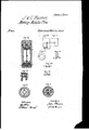
- Fig. 1 on Sheet 1 is a vertical section of the lower portion of a cylinder, with the pist-on ,shown therein, and alsoourimproved construction and adaptation oi' a short core with the die applied thereto.
- Fig. 2 is a horizontal sectionof the cylinder,taken in the line a b-iu Fig. 1, or just above the bridge, core, and' die.
- Fig. 3 is another-similar partial section of the same, taken-on the line c d in Fig. '1, or
- 0 is the piston face or end, (attachedto the body of the piston,) the various' parts of which are shown separate at l Figs. 13 to 18, inclusive,
- v D is the lower end or bottom of the cylinder, firmly attached thereto by bolts, and also to astrong tableor platform placed upona hollow pillar, which stands uponthe top of the usual ram of the hydraulic press. (The table and parts below are shown at Fig.r 22, sheet 2.), E is the' die, which is it'tedinto the bottom of the cylinder in arecess or cup, as showninthe draw-v ings. F F are adjusting-screws for'setting or regulating the situation of the die as regards the core.
- the chamber' may be of any convenient form, and, in fact, thel plate G andthe ring Z (hereinafter described) 'may' -both be dispensed withaltogether; vbut,as a snbstitntefor the plate G, we prefer the steel ring Z, whichmakes the chamber conical, and
- the aperture being thus of the form of an inverted cone; bntwe have sometimes made it cylindrical.
- Fig. 21 is a sectional representation (ou auother scale) of the chamber X as formed by the ring Z, with the die ⁇ E below and the bridge I above it.
- the steel'ringl rests-upon the die E, protects the adjusting-screws F F by interposition, andl forms a support for the 'bridge I.
- K, Figs. 1 and 19 shows the situation of A the aperture inthe upper ⁇ part of the cylinder, or side or end opposite tothe-dies,-
- throngh- whichthe cylinder is filled withv melted metaL'and which is immediately closed l by the passage oil,i.l.ie,piston;end.lThis is more eouvenientthan to withdraw the piston.
- Fig. 7, Sheet 2 is another vertical section of the lower part of a cylinder, showing a novel adaptation of our mechanism for mak# A ing four dierentjengths of pipes at one and the same time.
- Fig. 10 ⁇ is another horizontal section taken through the dies" and cores in the line a I iuFig. 7.- Fig, 1-1 is' a plan view of the bottom o f the cylinder', the diesl and cores be-v the cylinder; B B, the'zbottom of thesame. ⁇ Cj
- Fig. 8 is a'.
- Fig. 9 is a horizontal section or plan thepa Y v 51s,
- E 4E are wedges' '.for adjusting the vertical position of thedies .to the cores.
- F F are the cores or mandrels xed into or forming part of stocks orpieees of .metal G G, wlich arev mortised into one an-4 other, and also into the bottomvof the cylin-v recesses formed in the bottom of the cylinder,
- the bottom of the cylinder has four wells or 'chambers,- K K, formed in it, as shown more. parf- Y- ticularly in Fig. 11. to' allow of the passage of the pipe-metal to the di'erent dies and cores.
- Fig. 13, Sheet ,1 is a representation of the ⁇ end of the piston upon our improved construetion.
- Fig.l 14 .is asimilar representation with rts de'tached.- (Shown separate at Figs. 1b, 16,- 17, and 18,.) ais the body of the piston".
- b is the lower .end or faeeot the inten, attached to the body by the pin c. u the upper part of the piston.
- A Between the-in clined or conical-shaped sides'of the parts d and b is placed the ringe, (shown detached in plan in Fig.,1'lA and in section at Fig. 18,) and being cut-consequently it .will be obliged to expand and keep the pistontightlypaeked with the cylinder under great prsure, and thereby preventt-he escape of the metal;
- piston-faceA is attaehedto'the body a by means' of a pin,rh, passed through it, or in any other y convenient manner.
- Fig. 19 is a vertical section of acylinderand piston, showing' the adaptationof the guidepiece r bridge, through which the long core attached to the piston passes for the purpose of A keeping itcentral'withthedie.
- B' is the piston-body;
- C the fac'eorend ofthe piston;
- D the bottom of the cylinder;
- E the die.
- G is the thin steel plate. (Here ex-'.
- A'.'lhe pipe may bel received in a long descending cooling-trough, or may be :immediately wound upou'reelsas fast as' it is discharged from the machinery.
- the pipe-metal is represented in'I the drawy ings by a tint of red color. Y
- the chamber, and the die when usedto form pipes of metal under heat and pressure in the manner set forth.' or in any other manner substantially the sume.
Family
ID=
Similar Documents
| Publication | Publication Date | Title |
|---|---|---|
| US10265746B2 (en) | Rotary extrusion producing method for producing inner ring rib with large aspect ratio formed of hollow billet | |
| US3664411A (en) | Die-casting apparatus with ceramic shot duct liner | |
| US20180056353A1 (en) | Rotary Extrusion Producing Mold for Producing Inner Ring Rib with Large Aspect Ratio Formed of Hollow Billet | |
| US2112342A (en) | Pressure casting machine | |
| US2021A (en) | Peters | |
| USRE82E (en) | Improvement in machinery for makjnq metallic pipes | |
| US2276468A (en) | Extrusion die | |
| US3826122A (en) | Mandrel for extruding tubing | |
| US3085812A (en) | Pressing tools | |
| US819261A (en) | Apparatus for treating heated metal under pressure. | |
| US2266189A (en) | Extrusion die structure | |
| CN107999679A (zh) | 一种斗齿锻造模具及其下模组件 | |
| US2164397A (en) | Extrusion | |
| US5466A (en) | Lead-pipe machiiteby | |
| US2442142A (en) | Upset forging apparatus | |
| US2581550A (en) | Extrusion molding machine | |
| US1084881A (en) | Press for making pipes. | |
| US961128A (en) | Machine for forming seamless tubes. | |
| US1171344A (en) | Apparatus for concentric punching. | |
| US817085A (en) | Machine for making metal bars or rods. | |
| US5253A (en) | Lead-pipe machinery | |
| US1314366A (en) | Apparatus for forming hollow articles | |
| US54121A (en) | Improved machine for the manufacture of rod-solder | |
| US769181A (en) | Hydraulic press. | |
| US2812673A (en) | Mandrel guiding arrangement for billet piercing apparatus |