USRE44776E1 - Robust fine frequency and time estimation in mobile receivers - Google Patents
Robust fine frequency and time estimation in mobile receivers Download PDFInfo
- Publication number
- USRE44776E1 USRE44776E1 US13/645,498 US201213645498A USRE44776E US RE44776 E1 USRE44776 E1 US RE44776E1 US 201213645498 A US201213645498 A US 201213645498A US RE44776 E USRE44776 E US RE44776E
- Authority
- US
- United States
- Prior art keywords
- carrier
- offset
- sub
- timing offset
- symbols
- Prior art date
- Legal status (The legal status is an assumption and is not a legal conclusion. Google has not performed a legal analysis and makes no representation as to the accuracy of the status listed.)
- Expired - Fee Related, expires
Links
Images


Classifications
-
- H—ELECTRICITY
- H04—ELECTRIC COMMUNICATION TECHNIQUE
- H04L—TRANSMISSION OF DIGITAL INFORMATION, e.g. TELEGRAPHIC COMMUNICATION
- H04L27/00—Modulated-carrier systems
- H04L27/26—Systems using multi-frequency codes
- H04L27/2601—Multicarrier modulation systems
- H04L27/2647—Arrangements specific to the receiver only
- H04L27/2655—Synchronisation arrangements
- H04L27/2657—Carrier synchronisation
-
- H—ELECTRICITY
- H04—ELECTRIC COMMUNICATION TECHNIQUE
- H04L—TRANSMISSION OF DIGITAL INFORMATION, e.g. TELEGRAPHIC COMMUNICATION
- H04L27/00—Modulated-carrier systems
- H04L27/26—Systems using multi-frequency codes
- H04L27/2601—Multicarrier modulation systems
- H04L27/2647—Arrangements specific to the receiver only
- H04L27/2655—Synchronisation arrangements
- H04L27/2662—Symbol synchronisation
-
- H—ELECTRICITY
- H04—ELECTRIC COMMUNICATION TECHNIQUE
- H04L—TRANSMISSION OF DIGITAL INFORMATION, e.g. TELEGRAPHIC COMMUNICATION
- H04L27/00—Modulated-carrier systems
- H04L27/26—Systems using multi-frequency codes
- H04L27/2601—Multicarrier modulation systems
- H04L27/2647—Arrangements specific to the receiver only
- H04L27/2655—Synchronisation arrangements
- H04L27/2668—Details of algorithms
- H04L27/2673—Details of algorithms characterised by synchronisation parameters
- H04L27/2675—Pilot or known symbols
Definitions
- the embodiments herein generally relate to wireless communications, and, more particularly, to a method and apparatus for carrier frequency offset and timing offset estimation in a MediaFLOTM (Forward Link Only) system.
- MediaFLOTM Forward Link Only
- Multimedia communications provide a rich and immediate environment of image, graphics, sound, text and interaction through a range of technologies.
- An example of multimedia communication is streaming multimedia which is primarily a delivery of continuous synchronized media data.
- the streaming multimedia is constantly received by, and displayed to an end user while it is being delivered by a provider.
- Multiple technologies such as Integrated Services Digital Broadcasting-Terrestrial (ISDB-T), Terrestrial-Digital Multimedia Broadcasting (T-DMB), Satellite-Digital Multimedia Broadcasting (S-DMB), Digital Video Broadcasting-Handheld (DVB-H), and FLO (Forward Link Only) are used to address the delivery of streaming multimedia to mobile devices. These technologies have typically leveraged upon either third generation cellular/PCS, or digital terrestrial TV broadcast technologies.
- FLO technology was designed specifically for the efficient and economical distribution of the same multimedia content to millions of wireless subscribers simultaneously. Also, the FLO technology was designed from the ground up to be a multicasting network, which is overlaid upon a cellular network. It does not need to support any backward compatibility constraints. Thus, both the network infrastructure and the receiver devices are separate from those for the cellular/PCS network. Moreover, as the name suggests, the technology relies on the use of a forward link (network to device) only.
- FLO enables reducing the cost of delivering such content and enhancing the user experience, allowing consumers to “surf” channels of content on the same mobile handsets they use for traditional cellular voice and data services.
- MediaFLOTM technology can provide robust mobile performance and high capacity without compromising power consumption. The technology also reduces the network cost of delivering multimedia content by dramatically decreasing the number of transmitters needed to be deployed.
- MediaFLOTM technology-based multimedia multicasting complements wireless operators' cellular network data and voice services, delivering content to the same cellular handsets used on 3G networks.
- the MediaFLOTM wireless system has been designed to broadcast real time audio and video signals, apart from non-real time services to mobile users.
- the system complements existing networks and radically expands the ability to deliver desired content without impacting the voice and data services. Operators can leverage the MediaFLOTM system to increase average revenue per user (ARPU) and reduce churn by offering enhanced multimedia services.
- Content providers can take advantage of a new distribution channel to extend their brand to mobile users. Device manufacturers will benefit from increased demand for multimedia-enabled handsets as consumer appetite grows for the rich content provided through MediaFLOTM systems.
- the MediaFLOTM service is designed to provide the user with a viewing experience similar to a television viewing experience by providing a familiar type of program-guide user interface. Users can simply select a presentation package, or grouping of programs, just as they would select a channel to subscribe to on television. Once the programs are selected and subscribed to, the user can view the available programming content at any time. In addition to viewing high quality video and audio content and IP data, the user may also have access to related interactive services, including the option to purchase a music album, ring tone, or download of a song featured in a music program. The user can also purchase access to on-demand video programming, above and beyond the content featured on the program guide.
- the respective MediaFLOTM system transmission is carried out using tall and high power transmitters to ensure wide coverage in a given geographical area. Further, it is common to deploy 3-4 transmitters in most markets to ensure that the MediaFLOTM system signal reaches a significant portion of the population in a given market. During the acquisition process of a MediaFLOTM system data packet several determinations and computations are made to determine such aspects as frequency offsets for the respective wireless receiver. Given the nature of MediaFLOTM system broadcasts that support multimedia data acquisitions, efficient processing of such data and associated overhead information is paramount.
- the sampling time of the receiver is usually not commensurate with that of the transmitter, and a carrier and time offset exists between the transmitter and the receiver. Therefore, the resulting carrier and time offset need to be estimated and then corrected to ensure reliable quality communication.
- OFDM Orthogonal Frequency Division Multiplexing
- the phase difference between successive OFDM symbols are first taken on corresponding pilots to obtain a fine estimate of the carrier and time offset, and the channel frequency response are then estimated and equalized.
- the carrier offset estimation range are limited to +/ ⁇ 0.25 OFDM sub carrier spacing, which corresponds to about +/ ⁇ 340 Hz carrier frequency offset. In practice this range might not be sufficient. Accordingly, there remains a need for a novel Doppler frequency estimation technique that permits estimation of high Doppler frequencies to further increase the fine carrier frequency estimation range in MediaFLOTM receiver design to about +/ ⁇ 0.5 OFDM sub carrier spacing, which corresponds to about +/ ⁇ 680 Hz at almost no complexity increment.
- an embodiment herein provides a method of estimating a carrier frequency offset and a timing offset in a MediaFLOTM (Forward Link Only) system, and a program storage device readable by computer, tangibly embodying a program of instructions executable by said computer to perform the method of estimating a carrier frequency offset and a timing offset in a MediaFLOTM (Forward Link Only) system, wherein the method comprises receiving OFDM symbols; interpolating pilots on odd or even symbols of the received OFDM symbols; determining a phase difference between two successive symbols using the interpolated pilots; obtaining an estimate of the carrier frequency offset and the timing offset from the determined phase difference between two successive symbols; and correcting a sampling frequency in accordance with the estimated carrier frequency offset and timing offset.
- determining the phase difference occurs using relation:
- ⁇ k 2 ⁇ ⁇ ⁇ ( ⁇ f + ⁇ T u ⁇ k ) , wherein ⁇ k is a differential phase between two successive symbols of sub-carrier index k in rad/symbol, ⁇ f is the carrier offset between a receiver and a transmitter in said MediaFLOTM (Forward Link Only) receiver system in terms of sub-carrier bin duration,
- T T - T ′ T ′
- T is a transmitter sampling period and T′ is a receiver sampling period
- k is the sub-carrier index
- T u is an OFDM symbol duration excluding a guard interval.
- the method may further comprise determining ⁇ k for multiple sub-carrier index k using said relation; and representing the resulting values of ⁇ k graphically. Additionally, obtaining of the estimate of the carrier frequency offset may be derived as the mean of intercept of the graphically represented values of ⁇ k and the timing offset may be derived as the slope of the graphically represented values of ⁇ k .
- an estimate of the timing offset ⁇ ⁇ and the carrier frequency offset ⁇ ⁇ is obtained using:
- phase difference ⁇ k the timing offset ⁇
- carrier offset ⁇ f the carrier offset
- Another embodiment includes an apparatus for estimating a carrier frequency offset and a timing offset in a MediaFLOTM (Forward Link Only) system, wherein the apparatus comprises a receiver adapted to receive OFDM symbols; a processor adapted to interpolate pilots on odd or even symbols of the received OFDM symbols; a calculator adapted to determine a phase difference between two successive symbols using the interpolated pilots; an estimator adapted to obtain an estimate of the carrier frequency offset and the timing offset from the determined phase difference between two successive symbols; and means for correcting a sampling frequency in accordance with the estimated carrier frequency offset and timing offset.
- the apparatus comprises a receiver adapted to receive OFDM symbols; a processor adapted to interpolate pilots on odd or even symbols of the received OFDM symbols; a calculator adapted to determine a phase difference between two successive symbols using the interpolated pilots; an estimator adapted to obtain an estimate of the carrier frequency offset and the timing offset from the determined phase difference between two successive symbols; and means for correcting a sampling frequency in accordance with the estimated carrier frequency offset and
- the calculator may be further adapted to determine the phase difference using relation:
- ⁇ k 2 ⁇ ⁇ ⁇ ( ⁇ f + ⁇ T u ⁇ k ) , wherein ⁇ k is a differential phase between two successive symbols of sub-carrier index k in rad/symbol, ⁇ f is the carrier offset between a receiver and a transmitter in said MediaFLOTM (Forward Link Only) receiver system in terms of sub-carrier bin duration,
- T T - T ′ T ′
- T is a transmitter sampling period and T′ is a receiver sampling period
- k is the sub-carrier index
- T u is an OFDM symbol duration excluding a guard interval.
- the calculator may be further adapted to determine ⁇ k for multiple sub-carrier index k using said relation; and represent the resulting values of ⁇ k graphically.
- the estimate of the carrier frequency offset may be derived as the mean of intercept of the graphically represented values of ⁇ k and the timing offset may be derived as the slope of the graphically represented values of ⁇ k .
- an estimate of the timing offset ⁇ ⁇ and the carrier frequency offset ⁇ ⁇ is obtained using:
- phase difference ⁇ k the timing offset ⁇
- carrier offset ⁇ f the carrier offset
- FIG. 1 illustrates a FLO system for a MediaFLOTM system according to an embodiment herein;
- FIG. 2 is a graphical representation of the relationship between the differential phase and frequency and timing offset
- FIG. 3 illustrates the structure of scattered OFDM pilots considered in order to obtain an estimate of a straight line in a MediaFLOTM receiver design
- FIGS. 4A and 4B illustrate examples of Doppler fading effect on timing and carrier offset estimation
- FIG. 5 illustrates the structure of interpolated scattered pilots for a MediaFLOTM receiver design
- FIG. 6A illustrates a simulation result of a straight line obtained using a technique based on raw pilots
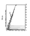
- FIG. 6B illustrates a simulation result of a straight line obtained using a technique based on interpolated pilots
- FIG. 7 is a block diagram illustrating an embodiment of a system for estimating a slope and a mean of a straight line obtained using a technique based on interpolated pilots;
- FIG. 8 is a flow diagram illustrating a preferred method according to an embodiment herein.
- FIG. 9 illustrates a schematic diagram of a computer architecture used in accordance with the embodiments herein.
- FIGS. 1 through 8 where similar reference characters denote corresponding features consistently throughout the figures, there are shown preferred embodiments.
- the FLO system is comprised of two parts: (a) The FLO network, which includes the collection of transmitters and the backhaul network, and (b) The FLO device, which may be any type of communicating devices such as a cell phone, computer, personal assistant, laptop, handheld, or gaming consoles, etc.
- FIG. 1 illustrates a FLO system 100 for a MediaFLOTM system.
- the system 100 includes one or more transmitters 110 that communicate across a wireless network 130 to one or more receivers 120 .
- a processor 125 receives and processes the symbol streams received by the receiver 120 .
- the FLO system 100 is utilized in developing an air interface for the MediaFLOTM mobile multicast system.
- the air interface uses Orthogonal Frequency Division Multiplexing (OFDM) as the modulation technique, which is also utilized by Digital Audio Broadcasting (DAB), (DVD-T), and (ISDB-T).
- OFDM Orthogonal Frequency Division Multiplexing
- DAB Digital Audio Broadcasting
- DVB Digital Audio Broadcasting
- ISDB-T Digital Audio Broadcasting
- FLO system 100 employs the concept of Single Frequency Network (SFN) operation.
- SFN Single Frequency Network
- the FLO system 100 multicasts several services.
- a service is an aggregation of one or more related data components, such as the video, audio, text or signaling associated with a service.
- the services are classified into two types based on their coverage area: Wide-area services and Local-area services.
- a Local-area service is multicast for reception within a metropolitan area.
- Wide-area services are multicast in one or more metropolitan areas.
- the term Local-area is used to denote the transmitters within a metropolitan area.
- the term Wide-area is used to denote transmitters in one or more metropolitan areas that multicast the same Wide-area services.
- a Wide-area contains one or more Local-areas, with the transmitters in the different Local-areas multicasting different local area services and in an embodiment, using different radio frequency (RF) center frequencies.
- RF radio frequency
- FLO services are carried over one or more logical channels. These logical channels are called Multicast Logical Channels (MLC).
- MLC Multicast Logical Channels
- An important aspect is that MLCs are distinguishable at the physical layer. For example, the video and audio components of a given service can be sent on two different MLCs.
- a FLO device (a receiver from the plurality of receivers 120 ) that is interested in the audio component can only receive the corresponding MLC without receiving the MLC for the video component, thereby saving battery resources.
- the statistical multiplexing of different services is achieved by varying only the MLC time and frequency allocations over prescribed time intervals to match the variability in the MLC's source rates.
- Statistical multiplexing in FLO enables the receivers 120 to demodulate and decode only the MLC(s) of interest.
- the data rates required by the services are expected to vary over a wide range, depending on their multimedia content.
- effective use of statistical multiplexing can significantly increase the number of services supported by a multicast system using a specified channel bandwidth.
- the sampling time of a receiver T′ is usually not commensurate with that of a transmitter T; i.e., T ⁇ T′.
- a carrier offset ⁇ f exists between the receiver and the transmitter. The phase difference between two successive OFDM symbols (assuming the corresponding OFDM sub-carriers do not carry information like the pilots carriers), then it can be shown that the following equation holds:
- ⁇ k 2 ⁇ ⁇ ⁇ ( ⁇ f + ⁇ T u ⁇ k ) ( 1 )
- ⁇ k is the differential phase between two successive symbols of sub-carrier index k in rad/symbol
- ⁇ f is the carrier offset between the receiver and the transmitter in terms of sub-carrier bin duration.
- T the transmitter sampling period and T′ is the receiver sampling period;
- k the sub-carrier index;
- T u the OFDM symbol duration excluding the guard interval.
- FIG. 2 is a graphical representation of equation (1).
- equation (1) is shown as a straight line 210 , and the slope of the straight line 210 equals the timing offset ⁇ ⁇ apart from the scaling factor T u .
- the mean intercept of the straight line 210 equals the carrier frequency offset ⁇ ⁇ .
- FIG. 3 illustrates the structure of scattered OFDM pilots considered in order to obtain an estimate of a straight line in a MediaFLOTM system receiver design according to an embodiment herein.
- the phase difference across OFDM pilots are taken every other symbols; i.e., either odd symbols 310 or even symbols 320 .
- An estimate of the timing offset ⁇ ⁇ and the carrier frequency offset ⁇ ⁇ may then be obtained as follows:
- FIGS. 4A and 4B illustrate examples of Doppler fading effect on timing and carrier offset estimation.
- the Doppler fading effect shown is of a TU6 channel with Doppler 150 Hz, timing offset 100 ppm, and delta angles even index 24 .
- the Doppler fading effect shown is of a ideal channel with timing offset 100 ppm, and delta angles even index 34 .
- the line 410 of FIG. 4A and the line 420 of FIG. 4B are not clean and may be very noisy, which leads to the wrap up of some values of ⁇ k .
- a moving averaging technique such as a leaky integrator may be used to smooth out the noisy effect.
- ⁇ k 4 ⁇ ⁇ ⁇ ( ⁇ f + ⁇ T u ⁇ k ) ( 4 )
- the pilots are interpolated on the odd symbols 310 or the even symbols 320 of FIG. 3 .
- FIG. 5 illustrates the structure of interpolated scattered pilots for a MediaFLOTM system receiver design according to an embodiment herein.
- the interpolated pilots are then used to determine the phase difference between two successive symbols instead of using the raw pilots over every other symbol.
- the corresponding differential phase may be then given by:
- ⁇ k 2 ⁇ ⁇ ⁇ ( ⁇ f + ⁇ T u ⁇ k ) ( 5 )
- FIG. 6A illustrates a simulation result of the straight line 610 obtained using a technique based on raw pilots.
- the carrier offset tolerance is about 0.10 bin with 50 ppm timing offset.
- the straight line 610 tends to wrap with an increase of the carrier offset tolerance from 0.10 bin.
- FIG. 6B illustrates a simulation result of the straight line 620 obtained using a technique based on interpolated pilots.
- the carrier offset tolerance is about 0.25 bin.
- the straight line 620 tends to wrap with further increase of the carrier offset tolerance from 0.25 bin.
- the technique using interpolated pilots doubles the estimation range of the carrier offset frequency to +/ ⁇ 0.5 OFDM sub carrier spacing, which corresponds to about +/ ⁇ 680 Hz at almost no complexity increment.
- FIG. 7 is a block diagram illustrating an embodiment of a system 700 for estimating a slope and a mean of a straight line obtained using a technique based on interpolated pilots.
- the system 700 comprises angle estimators 710 , 720 to estimate angles of the interpolated pilots.
- the angle estimator 710 estimates an angle of current pilots and the angle estimator 720 estimates an angle of the previous pilots.
- a calculator 730 estimates the phase difference ⁇ between the current pilot and the previous pilot.
- the resulting output of the calculator 730 is then provided to a slope estimator 740 and a mean estimator 750 .
- ⁇ is a straight line.
- the slope estimator 740 estimates the slope and the mean estimator 750 estimates the mean intercept of the straight line of ⁇ .
- the resulting output of the slope estimator 740 is provided to a line gradient leaky integrator 760 and the resulting output of the mean estimator 750 is provided to a line mean leaky integrator 770 .
- the resulting output of the line gradient leaky integrator 760 provides the slope of the straight line of ⁇ , wherein the slope equals the timing offset ⁇ ⁇ and the resulting output of the line mean leaky integrator 770 provides the mean intercept of the straight line of ⁇ , wherein the mean intercept equals the frequency offset ⁇ ⁇ .
- FIG. 8 illustrates a flow diagram illustrating a method of estimating a carrier frequency offset and a timing offset in a MediaFLOTM (Forward Link Only) system according to an embodiment herein, wherein the method comprises receiving ( 801 ) Orthogonal Frequency Division Multiplexing (OFDM) symbols; interpolating ( 803 ) pilots on odd or even symbols of the received OFDM symbols; determining ( 805 ) a phase difference between two successive symbols using the interpolated pilots; obtaining ( 807 ) an estimate of the carrier frequency offset and the timing offset from the determined phase difference between two successive symbols; and correcting ( 809 ) a sampling frequency in accordance with the estimated carrier frequency offset and timing offset.
- OFDM Orthogonal Frequency Division Multiplexing
- determining ( 805 ) the phase difference occurs using relation:
- ⁇ k 2 ⁇ ⁇ ⁇ ( ⁇ f + ⁇ T u ⁇ k ) , wherein ⁇ k is a differential phase between two successive symbols of sub-carrier index k in rad/symbol, ⁇ f is the carrier offset between a receiver and a transmitter in said MediaFLOTM (Forward Link Only) receiver system in terms of sub-carrier bin duration,
- T T - T ′ T ′
- T is a transmitter sampling period and T′ is a receiver sampling period
- k is the sub-carrier index
- T u is an OFDM symbol duration excluding a guard interval.
- the method may further comprise determining ⁇ k for multiple sub-carrier index k using said relation; and representing the resulting values of ⁇ k graphically. Additionally, obtaining ( 807 ) of the estimate of the carrier frequency offset may be derived as the mean of intercept of the graphically represented values of ⁇ k and the timing offset may be derived as the slope of the graphically represented values of ⁇ k .
- an estimate of the timing offset ⁇ ⁇ and the carrier frequency offset ⁇ ⁇ is obtained using:
- phase difference ⁇ k the timing offset ⁇
- carrier offset ⁇ f the carrier offset
- the techniques provided by the embodiments herein may be implemented on an integrated circuit chip (not shown).
- the chip design is created in a graphical computer programming language, and stored in a computer storage medium (such as a disk, tape, physical hard drive, or virtual hard drive such as in a storage access network). If the designer does not fabricate chips or the photolithographic masks used to fabricate chips, the designer transmits the resulting design by physical means (e.g., by providing a copy of the storage medium storing the design) or electronically (e.g., through the Internet) to such entities, directly or indirectly.
- the stored design is then converted into the appropriate format (e.g., GDSII) for the fabrication of photolithographic masks, which typically include multiple copies of the chip design in question that are to be formed on a wafer.
- the photolithographic masks are utilized to define areas of the wafer (and/or the layers thereon) to be etched or otherwise processed.
- the resulting integrated circuit chips can be distributed by the fabricator in raw wafer form (that is, as a single wafer that has multiple unpackaged chips), as a bare die, or in a packaged form.
- the chip is mounted in a single chip package (such as a plastic carrier, with leads that are affixed to a motherboard or other higher level carrier) or in a multichip package (such as a ceramic carrier that has either or both surface interconnections or buried interconnections).
- the chip is then integrated with other chips, discrete circuit elements, and/or other signal processing devices as part of either (a) an intermediate product, such as a motherboard, or (b) an end product.
- the end product can be any product that includes integrated circuit chips, ranging from toys and other low-end applications to advanced computer products having a display, a keyboard or other input device, and a central processor.
- the embodiments herein can take the form of an entirely hardware embodiment, an entirely software embodiment or an embodiment including both hardware and software elements.
- the embodiments that are implemented in software include but are not limited to, firmware, resident software, microcode, etc.
- a computer-usable or computer-readable medium can be any apparatus that can comprise, store, communicate, propagate, or transport the program for use by or in connection with the instruction execution system, apparatus, or device.
- the medium can be an electronic, magnetic, optical, electromagnetic, infrared, or semiconductor system (or apparatus or device) or a propagation medium.
- Examples of a computer-readable medium include a semiconductor or solid state memory, magnetic tape, a removable computer diskette, a random access memory (RAM), a read-only memory (ROM), a rigid magnetic disk and an optical disk.
- Current examples of optical disks include compact disk-read only memory (CD-ROM), compact disk-read/write (CD-R/W) and DVD.
- a data processing system suitable for storing and/or executing program code will include at least one processor coupled directly or indirectly to memory elements through a system bus.
- the memory elements can include local memory employed during actual execution of the program code, bulk storage, and cache memories which provide temporary storage of at least some program code in order to reduce the number of times code must be retrieved from bulk storage during execution.
- I/O devices can be coupled to the system either directly or through intervening I/O controllers.
- Network adapters may also be coupled to the system to enable the data processing system to become coupled to other data processing systems or remote printers or storage devices through intervening private or public networks. Modems, cable modem and Ethernet cards are just a few of the currently available types of network adapters.
- FIG. 9 A representative hardware environment for practicing the embodiments herein is depicted in FIG. 9 .
- the system 900 comprises at least one processor or central processing unit (CPU) 910 .
- the CPUs 910 are interconnected via system bus 912 to various devices such as a random access memory (RAM) 914 , read-only memory (ROM) 916 , and an input/output (I/O) adapter 918 .
- RAM random access memory
- ROM read-only memory
- I/O input/output
- the I/O adapter 918 can connect to peripheral devices, such as disk units 911 and tape drives 913 , or other program storage devices that are readable by the system 900 .
- the system 900 can read the inventive instructions on the program storage devices and follow these instructions to execute the methodology of the embodiments herein.
- the system 900 further includes a user interface adapter 919 that connects a keyboard 915 , mouse 917 , speaker 924 , microphone 922 , and/or other user interface devices such as a touch screen device (not shown) to the bus 912 to gather user input.
- a communication adapter 920 connects the bus 912 to a data processing network 925
- a display adapter 921 connects the bus 912 to a display device 923 which may be embodied as an output device such as a monitor, printer, or transmitter, for example.
- the sampling time of the receiver is not commensurate with that of the transmitter, and a carrier and time offset exists between the transmitter and the receiver.
- the carrier and time offset need to be estimated and then corrected to ensure reliable quality communication. Accordingly, the embodiments herein provide a manner of achieving this.
Abstract
Description
wherein Δφk is a differential phase between two successive symbols of sub-carrier index k in rad/symbol, Δf is the carrier offset between a receiver and a transmitter in said MediaFLO™ (Forward Link Only) receiver system in terms of sub-carrier bin duration,
where T is a transmitter sampling period and T′ is a receiver sampling period, k is the sub-carrier index, and Tu is an OFDM symbol duration excluding a guard interval.
wherein L is a total number pilots involved in the estimation within one OFDM symbol.
wherein when there is no timing offset, Δf takes a maximum value when Δφk=±π.
where Δφk is the differential phase between two successive symbols of sub-carrier index k in rad/symbol; Δf is the carrier offset between the receiver and the transmitter in terms of sub-carrier bin duration.
where T is the transmitter sampling period and T′ is the receiver sampling period; k is the sub-carrier index; Tu is the OFDM symbol duration excluding the guard interval.
φΔ=slope(Δφk)=δ/Tu
φμ=E[Δφk]=Δf (2)
where L is the total number pilots involved in the estimation within one OFDM symbol.
wherein Δφk is a differential phase between two successive symbols of sub-carrier index k in rad/symbol, Δf is the carrier offset between a receiver and a transmitter in said MediaFLO™ (Forward Link Only) receiver system in terms of sub-carrier bin duration,
where T is a transmitter sampling period and T′ is a receiver sampling period, k is the sub-carrier index, and Tu is an OFDM symbol duration excluding a guard interval.
wherein L is a total number pilots involved in the estimation within one OFDM symbol.
wherein when there is no timing offset, Δf takes a maximum value when Δφk=±π.
Claims (23)
Priority Applications (1)
| Application Number | Priority Date | Filing Date | Title |
|---|---|---|---|
| US13/645,498 USRE44776E1 (en) | 2008-04-04 | 2012-10-04 | Robust fine frequency and time estimation in mobile receivers |
Applications Claiming Priority (2)
| Application Number | Priority Date | Filing Date | Title |
|---|---|---|---|
| US12/062,774 US7944999B2 (en) | 2008-04-04 | 2008-04-04 | Robust fine frequency and time estimation in mobile multimedia multicast system receivers |
| US13/645,498 USRE44776E1 (en) | 2008-04-04 | 2012-10-04 | Robust fine frequency and time estimation in mobile receivers |
Related Parent Applications (1)
| Application Number | Title | Priority Date | Filing Date |
|---|---|---|---|
| US12/062,774 Reissue US7944999B2 (en) | 2008-04-04 | 2008-04-04 | Robust fine frequency and time estimation in mobile multimedia multicast system receivers |
Publications (1)
| Publication Number | Publication Date |
|---|---|
| USRE44776E1 true USRE44776E1 (en) | 2014-02-25 |
Family
ID=41133256
Family Applications (2)
| Application Number | Title | Priority Date | Filing Date |
|---|---|---|---|
| US12/062,774 Ceased US7944999B2 (en) | 2008-04-04 | 2008-04-04 | Robust fine frequency and time estimation in mobile multimedia multicast system receivers |
| US13/645,498 Expired - Fee Related USRE44776E1 (en) | 2008-04-04 | 2012-10-04 | Robust fine frequency and time estimation in mobile receivers |
Family Applications Before (1)
| Application Number | Title | Priority Date | Filing Date |
|---|---|---|---|
| US12/062,774 Ceased US7944999B2 (en) | 2008-04-04 | 2008-04-04 | Robust fine frequency and time estimation in mobile multimedia multicast system receivers |
Country Status (1)
| Country | Link |
|---|---|
| US (2) | US7944999B2 (en) |
Families Citing this family (5)
| Publication number | Priority date | Publication date | Assignee | Title |
|---|---|---|---|---|
| US8897385B2 (en) * | 2009-10-20 | 2014-11-25 | Maxlinear, Inc. | Doppler estimator for OFDM systems |
| DE102010054856A1 (en) | 2010-12-17 | 2012-06-21 | Rohde & Schwarz Gmbh & Co. Kg | Method for estimating offsets of common automated sampling and carrier frequencies and transmission delay of transmitter, involves measuring carrier frequency spacing based on pilot symbol and conjugate complex pilot symbol |
| CN102790737B (en) * | 2011-05-17 | 2017-11-28 | 中兴通讯股份有限公司 | The synchronous method and device of a kind of system |
| WO2015012816A1 (en) * | 2013-07-23 | 2015-01-29 | Intel IP Corporation | Method for improving spectral efficiency in wi-fi ofdm systems |
| CN108632002B (en) * | 2017-03-24 | 2021-06-01 | 华为技术有限公司 | Signal sending method, receiving method, device and system in wireless communication |
Citations (12)
| Publication number | Priority date | Publication date | Assignee | Title |
|---|---|---|---|---|
| US20030169682A1 (en) * | 2002-02-07 | 2003-09-11 | Nongji Chen | Multicarrier systems |
| US20040008618A1 (en) * | 1998-05-26 | 2004-01-15 | Naganori Shirakata | Modulator, demodulator, and transmission system for use in OFDM transmission |
| US6774829B2 (en) * | 2002-10-08 | 2004-08-10 | Hitachi Kokusai Electric Inc. | Apparatus and method for receiving signals including data carriers and pilot carriers modulated by multi-carrier modulation method |
| US20060176802A1 (en) | 2005-02-04 | 2006-08-10 | Samsung Electronics Co., Ltd. | Apparatus and method for compensating for frequency offset in wireless communication system |
| US20080219340A1 (en) * | 2003-09-12 | 2008-09-11 | Zarbana Digital Fund Llc | Frequency domain equalizer for wireless communications system |
| US20090046816A1 (en) | 2007-07-04 | 2009-02-19 | Lg Electronics Inc. | Digital broadcasting system and method of processing data |
| US7627049B2 (en) | 2005-08-22 | 2009-12-01 | Samsung Electronics Co., Ltd. | Sampling frequency offset tracking method and OFDM system using the same |
| US7693039B2 (en) | 2005-11-29 | 2010-04-06 | Samsung Electronics Co., Ltd. | Apparatus and method for carrier frequency synchronization in an OFDM system |
| US7706823B2 (en) | 2005-07-01 | 2010-04-27 | Sequans Communications | Method and system for synchronizing a base station of a wireless communication system and a subscriber communication equipment |
| US7733971B2 (en) | 2005-11-30 | 2010-06-08 | Samsung Electronics Co., Ltd. | Apparatus and method for recovering frequency in an orthogonal frequency division multiplexing system |
| US8270509B2 (en) * | 2007-05-03 | 2012-09-18 | Telefonaktiebolaget L M Ericsson (Publ) | Determining a frequency error in a receiver of a wireless communications system |
| US8345783B1 (en) * | 2007-04-06 | 2013-01-01 | Olympus Corporation | Phase tracking system and method |
-
2008
- 2008-04-04 US US12/062,774 patent/US7944999B2/en not_active Ceased
-
2012
- 2012-10-04 US US13/645,498 patent/USRE44776E1/en not_active Expired - Fee Related
Patent Citations (12)
| Publication number | Priority date | Publication date | Assignee | Title |
|---|---|---|---|---|
| US20040008618A1 (en) * | 1998-05-26 | 2004-01-15 | Naganori Shirakata | Modulator, demodulator, and transmission system for use in OFDM transmission |
| US20030169682A1 (en) * | 2002-02-07 | 2003-09-11 | Nongji Chen | Multicarrier systems |
| US6774829B2 (en) * | 2002-10-08 | 2004-08-10 | Hitachi Kokusai Electric Inc. | Apparatus and method for receiving signals including data carriers and pilot carriers modulated by multi-carrier modulation method |
| US20080219340A1 (en) * | 2003-09-12 | 2008-09-11 | Zarbana Digital Fund Llc | Frequency domain equalizer for wireless communications system |
| US20060176802A1 (en) | 2005-02-04 | 2006-08-10 | Samsung Electronics Co., Ltd. | Apparatus and method for compensating for frequency offset in wireless communication system |
| US7706823B2 (en) | 2005-07-01 | 2010-04-27 | Sequans Communications | Method and system for synchronizing a base station of a wireless communication system and a subscriber communication equipment |
| US7627049B2 (en) | 2005-08-22 | 2009-12-01 | Samsung Electronics Co., Ltd. | Sampling frequency offset tracking method and OFDM system using the same |
| US7693039B2 (en) | 2005-11-29 | 2010-04-06 | Samsung Electronics Co., Ltd. | Apparatus and method for carrier frequency synchronization in an OFDM system |
| US7733971B2 (en) | 2005-11-30 | 2010-06-08 | Samsung Electronics Co., Ltd. | Apparatus and method for recovering frequency in an orthogonal frequency division multiplexing system |
| US8345783B1 (en) * | 2007-04-06 | 2013-01-01 | Olympus Corporation | Phase tracking system and method |
| US8270509B2 (en) * | 2007-05-03 | 2012-09-18 | Telefonaktiebolaget L M Ericsson (Publ) | Determining a frequency error in a receiver of a wireless communications system |
| US20090046816A1 (en) | 2007-07-04 | 2009-02-19 | Lg Electronics Inc. | Digital broadcasting system and method of processing data |
Non-Patent Citations (1)
| Title |
|---|
| Chari, M. et al., "FLO Physical Layer: An Overview," IEEE Transactions on Broadcasting, vol. 53, No. 1, Mar. 2007, pp. 145-160. |
Also Published As
| Publication number | Publication date |
|---|---|
| US7944999B2 (en) | 2011-05-17 |
| US20090252239A1 (en) | 2009-10-08 |
Similar Documents
| Publication | Publication Date | Title |
|---|---|---|
| US8102791B2 (en) | Interleaver address generation in turbo decoders for mobile multimedia multicast system communication systems | |
| USRE44622E1 (en) | Coarse carrier frequency offset estimation for a receiver | |
| US20090252263A1 (en) | Estimating doppler frequency in isdb-t systems | |
| USRE44776E1 (en) | Robust fine frequency and time estimation in mobile receivers | |
| US7821916B2 (en) | Timing and frequency acquisition for mediaflo systems | |
| US7974364B2 (en) | Doppler frequency estimation and adaptation for mobile multimedia multicast systems | |
| US7903750B2 (en) | System and method for determining transmission parameters in an orthogonal frequency-division multiplexed data stream | |
| JP2009515490A (en) | Modulation type determination for transmitter performance evaluation | |
| JP4961038B2 (en) | Apparatus and method for removing common phase error in DVB-T / H receiver | |
| US20090268665A1 (en) | Method and Apparatus for Locating MediaFLO Capable Wireless Devices | |
| US8036292B2 (en) | Segmented-frame synchronization for ISDB-T and ISDB-TSB receiver | |
| US8670505B2 (en) | Early detection of segment type using BPSK and DBPSK modulated carriers in ISDB-T receivers | |
| JP5065483B2 (en) | Apparatus and method for removing common phase error in DVB-T / H receiver | |
| US8086940B2 (en) | Iterative decoding between turbo and RS decoders for improving bit error rate and packet error rate | |
| US7733968B2 (en) | Evaluation of transmitter performance | |
| US7907637B2 (en) | Fast acquisition in mobile multimedia multicast systems | |
| US7855959B2 (en) | Fast common overhead services acquisition for MediaFLO | |
| US7804846B2 (en) | Robust deframing of MAC layer packets for mobile multimedia multicast system | |
| TWI333349B (en) | Evaluation of transmitter performance | |
| US7751309B2 (en) | WIC and LIC estimation in MediaFLO systems | |
| US7940865B2 (en) | Re-acquisition of symbol index in the presence of sleep timer errors for mobile multimedia multicast systems | |
| CN100499628C (en) | Low power consumption asymmetric Fourier transform modulation/demodulation device |
Legal Events
| Date | Code | Title | Description |
|---|---|---|---|
| AS | Assignment |
Owner name: NEWPORT MEDIA, INC., CALIFORNIA Free format text: ASSIGNMENT OF ASSIGNORS INTEREST;ASSIGNORS:MA, JUN;YOUSEF, NABIL;SIGNING DATES FROM 20080301 TO 20080303;REEL/FRAME:029080/0600 |
|
| AS | Assignment |
Owner name: PINNACLE VENTURES, L.L.C., CALIFORNIA Free format text: SECURITY AGREEMENT;ASSIGNORS:NEWPORT MEDIA, INC., A DELAWARE CORPORATION;NEWPORT MEDIA, INC., A CALIFORNIA CORPORATION;REEL/FRAME:029818/0138 Effective date: 20130215 |
|
| AS | Assignment |
Owner name: HORIZON TECHNOLOGY FINANCE CORPORATION, AS COLLATE Free format text: SECURITY AGREEMENT;ASSIGNOR:NEWPORT MEDIA, INC.;REEL/FRAME:029956/0891 Effective date: 20121214 |
|
| FPAY | Fee payment |
Year of fee payment: 4 |
|
| AS | Assignment |
Owner name: MORGAN STANLEY SENIOR FUNDING, INC., AS COLLATERAL Free format text: PATENT SECURITY AGREEMENT;ASSIGNOR:NEWPORT MEDIA, INC.;REEL/FRAME:033689/0195 Effective date: 20140902 Owner name: MORGAN STANLEY SENIOR FUNDING, INC., AS COLLATERAL Free format text: PATENT SECURITY AGREEMENT;ASSIGNOR:ATMEL WIRELESS MCU TECHNOLOGIES CORPORATION;REEL/FRAME:033689/0214 Effective date: 20140902 |
|
| AS | Assignment |
Owner name: ATMEL CORPORATION, CALIFORNIA Free format text: TERMINATION OF SECURITY;ASSIGNOR:NEWPORT MEDIA, INC.;REEL/FRAME:033908/0242 Effective date: 20140618 Owner name: ATMEL CORPORATION, CALIFORNIA Free format text: TERMINATION OF SECURITY;ASSIGNOR:NEWPORT MEDIA, INC.;REEL/FRAME:033907/0748 Effective date: 20140618 Owner name: ATMEL CORPORATION, CALIFORNIA Free format text: TERMINATION OF SECURITY;ASSIGNOR:PINNACLE VENTURES, L.L.C.;REEL/FRAME:033908/0435 Effective date: 20140801 Owner name: ATMEL CORPORATION, CALIFORNIA Free format text: TERMINATION OF SECURITY;ASSIGNOR:NEWPORT MEDIA, INC.;REEL/FRAME:033907/0775 Effective date: 20140618 Owner name: ATMEL CORPORATION, CALIFORNIA Free format text: TERMINATION OF SECURITY;ASSIGNOR:HORIZON TECHNOLOGY FINANCE CORPORATION;REEL/FRAME:033907/0702 Effective date: 20140801 Owner name: ATMEL CORPORATION, CALIFORNIA Free format text: TERMINATION OF SECURITY;ASSIGNOR:BRIDGE BANK, NATIONAL ASSOCIATION;REEL/FRAME:033907/0517 Effective date: 20140801 Owner name: ATMEL CORPORATION, CALIFORNIA Free format text: TERMINATION OF SECURITY;ASSIGNOR:PINNACLE VENTURES, L.L.C.;REEL/FRAME:033908/0379 Effective date: 20140801 |
|
| FEPP | Fee payment procedure |
Free format text: PAT HOLDER NO LONGER CLAIMS SMALL ENTITY STATUS, ENTITY STATUS SET TO UNDISCOUNTED (ORIGINAL EVENT CODE: STOL); ENTITY STATUS OF PATENT OWNER: LARGE ENTITY |
|
| FEPP | Fee payment procedure |
Free format text: PAYOR NUMBER ASSIGNED (ORIGINAL EVENT CODE: ASPN); ENTITY STATUS OF PATENT OWNER: LARGE ENTITY |
|
| AS | Assignment |
Owner name: ATMEL CORPORATION, CALIFORNIA Free format text: ASSIGNMENT OF ASSIGNORS INTEREST;ASSIGNOR:NEWPORT MEDIA, INC.;REEL/FRAME:034705/0090 Effective date: 20141216 |
|
| AS | Assignment |
Owner name: NEWPORT MEDIA, INC., CALIFORNIA Free format text: TERMINATION AND RELEASE OF SECURITY INTEREST IN PATENT COLLATERAL;ASSIGNOR:MORGAN STANLEY SENIOR FUNDING, INC.;REEL/FRAME:038364/0659 Effective date: 20160404 Owner name: ATMEL WIRELESS MCU TECHNOLOGIES CORPORATION, CALIF Free format text: TERMINATION AND RELEASE OF SECURITY INTEREST IN PATENT COLLATERAL;ASSIGNOR:MORGAN STANLEY SENIOR FUNDING, INC.;REEL/FRAME:038364/0615 Effective date: 20160404 |
|
| AS | Assignment |
Owner name: JPMORGAN CHASE BANK, N.A., AS ADMINISTRATIVE AGENT, ILLINOIS Free format text: SECURITY INTEREST;ASSIGNOR:ATMEL CORPORATION;REEL/FRAME:041715/0747 Effective date: 20170208 Owner name: JPMORGAN CHASE BANK, N.A., AS ADMINISTRATIVE AGENT Free format text: SECURITY INTEREST;ASSIGNOR:ATMEL CORPORATION;REEL/FRAME:041715/0747 Effective date: 20170208 |
|
| AS | Assignment |
Owner name: JPMORGAN CHASE BANK, N.A., AS ADMINISTRATIVE AGENT, ILLINOIS Free format text: SECURITY INTEREST;ASSIGNORS:MICROCHIP TECHNOLOGY INCORPORATED;SILICON STORAGE TECHNOLOGY, INC.;ATMEL CORPORATION;AND OTHERS;REEL/FRAME:046426/0001 Effective date: 20180529 Owner name: JPMORGAN CHASE BANK, N.A., AS ADMINISTRATIVE AGENT Free format text: SECURITY INTEREST;ASSIGNORS:MICROCHIP TECHNOLOGY INCORPORATED;SILICON STORAGE TECHNOLOGY, INC.;ATMEL CORPORATION;AND OTHERS;REEL/FRAME:046426/0001 Effective date: 20180529 |
|
| AS | Assignment |
Owner name: WELLS FARGO BANK, NATIONAL ASSOCIATION, AS NOTES COLLATERAL AGENT, CALIFORNIA Free format text: SECURITY INTEREST;ASSIGNORS:MICROCHIP TECHNOLOGY INCORPORATED;SILICON STORAGE TECHNOLOGY, INC.;ATMEL CORPORATION;AND OTHERS;REEL/FRAME:047103/0206 Effective date: 20180914 Owner name: WELLS FARGO BANK, NATIONAL ASSOCIATION, AS NOTES C Free format text: SECURITY INTEREST;ASSIGNORS:MICROCHIP TECHNOLOGY INCORPORATED;SILICON STORAGE TECHNOLOGY, INC.;ATMEL CORPORATION;AND OTHERS;REEL/FRAME:047103/0206 Effective date: 20180914 |
|
| FEPP | Fee payment procedure |
Free format text: MAINTENANCE FEE REMINDER MAILED (ORIGINAL EVENT CODE: REM.); ENTITY STATUS OF PATENT OWNER: LARGE ENTITY |
|
| LAPS | Lapse for failure to pay maintenance fees |
Free format text: PATENT EXPIRED FOR FAILURE TO PAY MAINTENANCE FEES (ORIGINAL EVENT CODE: EXP.); ENTITY STATUS OF PATENT OWNER: LARGE ENTITY |
|
| AS | Assignment |
Owner name: MICROSEMI STORAGE SOLUTIONS, INC., ARIZONA Free format text: RELEASE BY SECURED PARTY;ASSIGNOR:JPMORGAN CHASE BANK, N.A., AS ADMINISTRATIVE AGENT;REEL/FRAME:059333/0222 Effective date: 20220218 Owner name: MICROSEMI CORPORATION, ARIZONA Free format text: RELEASE BY SECURED PARTY;ASSIGNOR:JPMORGAN CHASE BANK, N.A., AS ADMINISTRATIVE AGENT;REEL/FRAME:059333/0222 Effective date: 20220218 Owner name: ATMEL CORPORATION, ARIZONA Free format text: RELEASE BY SECURED PARTY;ASSIGNOR:JPMORGAN CHASE BANK, N.A., AS ADMINISTRATIVE AGENT;REEL/FRAME:059333/0222 Effective date: 20220218 Owner name: SILICON STORAGE TECHNOLOGY, INC., ARIZONA Free format text: RELEASE BY SECURED PARTY;ASSIGNOR:JPMORGAN CHASE BANK, N.A., AS ADMINISTRATIVE AGENT;REEL/FRAME:059333/0222 Effective date: 20220218 Owner name: MICROCHIP TECHNOLOGY INCORPORATED, ARIZONA Free format text: RELEASE BY SECURED PARTY;ASSIGNOR:JPMORGAN CHASE BANK, N.A., AS ADMINISTRATIVE AGENT;REEL/FRAME:059333/0222 Effective date: 20220218 |
|
| AS | Assignment |
Owner name: ATMEL CORPORATION, ARIZONA Free format text: RELEASE BY SECURED PARTY;ASSIGNOR:JPMORGAN CHASE BANK, N.A., AS ADMINISTRATIVE AGENT;REEL/FRAME:059262/0105 Effective date: 20220218 |
|
| AS | Assignment |
Owner name: MICROSEMI STORAGE SOLUTIONS, INC., ARIZONA Free format text: RELEASE BY SECURED PARTY;ASSIGNOR:WELLS FARGO BANK, NATIONAL ASSOCIATION, AS NOTES COLLATERAL AGENT;REEL/FRAME:059358/0001 Effective date: 20220228 Owner name: MICROSEMI CORPORATION, ARIZONA Free format text: RELEASE BY SECURED PARTY;ASSIGNOR:WELLS FARGO BANK, NATIONAL ASSOCIATION, AS NOTES COLLATERAL AGENT;REEL/FRAME:059358/0001 Effective date: 20220228 Owner name: ATMEL CORPORATION, ARIZONA Free format text: RELEASE BY SECURED PARTY;ASSIGNOR:WELLS FARGO BANK, NATIONAL ASSOCIATION, AS NOTES COLLATERAL AGENT;REEL/FRAME:059358/0001 Effective date: 20220228 Owner name: SILICON STORAGE TECHNOLOGY, INC., ARIZONA Free format text: RELEASE BY SECURED PARTY;ASSIGNOR:WELLS FARGO BANK, NATIONAL ASSOCIATION, AS NOTES COLLATERAL AGENT;REEL/FRAME:059358/0001 Effective date: 20220228 Owner name: MICROCHIP TECHNOLOGY INCORPORATED, ARIZONA Free format text: RELEASE BY SECURED PARTY;ASSIGNOR:WELLS FARGO BANK, NATIONAL ASSOCIATION, AS NOTES COLLATERAL AGENT;REEL/FRAME:059358/0001 Effective date: 20220228 |