USRE19663E - Automatic cam grinding machine - Google Patents
Automatic cam grinding machine Download PDFInfo
- Publication number
- USRE19663E USRE19663E US19663DE USRE19663E US RE19663 E USRE19663 E US RE19663E US 19663D E US19663D E US 19663DE US RE19663 E USRE19663 E US RE19663E
- Authority
- US
- United States
- Prior art keywords
- wheel
- cam
- carriage
- motor
- lever
- Prior art date
- Legal status (The legal status is an assumption and is not a legal conclusion. Google has not performed a legal analysis and makes no representation as to the accuracy of the status listed.)
- Expired
Links
Images


Classifications
-
- B—PERFORMING OPERATIONS; TRANSPORTING
- B24—GRINDING; POLISHING
- B24B—MACHINES, DEVICES, OR PROCESSES FOR GRINDING OR POLISHING; DRESSING OR CONDITIONING OF ABRADING SURFACES; FEEDING OF GRINDING, POLISHING, OR LAPPING AGENTS
- B24B19/00—Single-purpose machines or devices for particular grinding operations not covered by any other main group
- B24B19/08—Single-purpose machines or devices for particular grinding operations not covered by any other main group for grinding non-circular cross-sections, e.g. shafts of elliptical or polygonal cross-section
- B24B19/12—Single-purpose machines or devices for particular grinding operations not covered by any other main group for grinding non-circular cross-sections, e.g. shafts of elliptical or polygonal cross-section for grinding cams or camshafts
Definitions
- Another object is to provide a means for au tomatically feeding the wheel into the work at the proper speed and withdraw it when the work is finished.
- Fig. 3 a front elevation showing the relative position of the master cam and the cam shaft which is being ground
- Fig. 16 a right elevation of the head stock partly in section showing the method of rotating the work and the master cam in unison.
- Fig. 17 a right hand elevation of the head stock 10 illustrating means for swinging the work toward and away from the wheel so as to grind the cam to the desired shape
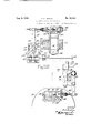
- Fig. 23 a front elevation of the wheel feed motor
- Fig. 24 a vertical longitudinal section of said motor.
- a spring I32 draws the arm I 28 toward its uppermost position and a plunger I33 forced rearwardly by a spring 134 tends tomove the hook I35 into engagement with the pin I28 on said arm.
- a fixed abutment I36 (Figs. 10 and 12) on the cover SI has a cam face cooperating with a cam face at I31 on the hook I35 to disengage the same from the pin I28 when the parts are lifted sufliciently high by spring I32.
- the piston I56 is slidably mounted in a cylinder I51 formed in the cover BI and is provided at its lower end with a roller I58 engaging the upper face of the roller bracket I69.
- the chamber I51 has a single port I59 opening into a valve chamber provided with an inlet port I60 (Figs. 1 and. 22) and an exhaust port IBI.
- balanced piston valve I62 is located in said valve chamber and said valve has a stem I63 adjustably connected to the lever I55 with provision for lost motion.
- the lever I55 has a vertical arm and a laterally extending inclined arm provided at its outer end with a roller I58.
- a double-acting spring-pressed plunger I65 is mounted approximately in line with said arm so as to force the lever toward its extreme position in either direction of its movement. It will be seen that the detent I53 and the plunger 165 will hold the lever I55 and the valve I62 in the position indicated, so that piston I55 will not move until the detent I53 is retracted.
- the grinding wheel spindle 98 is provided with a worm 286 meshing with teeth on a pinion 281 which is loose on a shaft 288.
- the shaft has eccentric portions at each end engaging forks in levers 289 pivoted at 2). These levers are connected by means of links 2 to a bronze collar 2I2 surrounding the shaft, said forks being pivoted to the collar at 2I3.
- a cam grinding machine a rotary wheel, a tilting support therefor, a bracket tiltable on an axis parallel to that of the wheel, means on said bracket for supporting a camshaft, and means including a master camshaft for tilting said bracket, and means for tilting said bracket away from the grinding wheel, substantially as set forth.
- a cam grinding machine a rotary wheel, a tilting support therefor, a work carriage, means on the carriage for supporting and rotating a camshaft, a cam for tilting the wheel supporting means, an oscillatory fluid motor for driving said cam alternately in opposite directions, a travers ing work carriage, means for moving the work carriage step-by-step to bring successive cams into the field of operation of the wheel, and means operated by said fluid motor for controlling the step-by-step movements of the carriage, substantially as set forth.
- a cam grinding machine comprising a rotary wheel, a traversing work carriage, a tilting bracket on the work carriage, means for moving the carriage intermittently to bring successive cams into the field of operation of said wheel, means for tilting the bracket to prevent interference with said traversing movement including a fluid motor, wheel feeding means including a fluid motor, means operated by the wheel feeding means in the extreme forward position of the wheel for setting the first-named fluid motor in action, and automatic means for putting said motor out of action for a predetermined traverse of the work carriage, substantially as set forth.
- a cam grinding machine a rotary wheel, a tilting support therefor, a work carriage, means on the carriage for supporting and rotating a camshaft, a cam for tilting the wheel supporting means, a fluid motor for driving said cam alternately in opposite directions, a traversing work carriage, a fluid motor for operating said carriage, means operated by said first-named fluid motor for setting the second fluid motor in action at intervals to move the carriage intermittently in one direction, the said means comprising a dog wheel, an irreversible dog on said dog wheel, a retaining pin, operative connection between the said dog and the said retaining pin, the said operative connection being adapted to withdraw the retaining pin when the motor operates in one direction, a valve operating arm held in position by said pin, a spring pressed plunger for operating the said arm, a valve controlled by said arm, a piston operated by said valve, and a reversing valzle operated by said piston, substantially as set for h.
Landscapes
- Engineering & Computer Science (AREA)
- Mechanical Engineering (AREA)
- Grinding And Polishing Of Tertiary Curved Surfaces And Surfaces With Complex Shapes (AREA)
Description
I Aug. 6, 1935. R. K. ROWELL AUTOMATIC CAM GRINDING MACHINE Original Filed March 6, 1926 14 Sheets-Sheet l INVENTOR. RKROu/ELL.
ATTORNEZ R. K. ROWELL Aug. 6, 1935.
AUTOMATIC CAM GRINDING MACHINE Original Filed March 6, 1926 14 Sheets-Sheet 2 INVENTOR- HJfi'Ro WELL- Egg.
A TORNEY.
A118. 1935- R. K. ROVJELL Re. 19,663
AUTOMATIC CAM GRINDING MACHINE Original Filed March 6, 1926 14 Sheets-Sheet 5 Fig.3.
IN VEN TOR.
R.K.R0mn.1..
\ Aq'TORNEK R. K. ROWELL Aug. 6, 1935.
AUTOMATIC CAM GRINDING MACHINE Original Filed March 6, 1926 14 Sheets-Sheet 4 IN V EN TOR. EJt'. Ra WELL TTORNEY.
Fig.4.
Aug. 6, 1935. R. K, ROWELL AUTOMATIC CAM GRINDING MACHINE Original Filed March 6, 1926 14 Sheets-Sheet 5 Fig.5.
IN VENTOR. E. EHO WE'LL.
A TTORNEK R. K FZOWELL Aug. 6, 1935.
AUTOMATIC CAM GRINDING MACHINE Original Filed March 6, 1926 14 Sheets-Sheet 6 INVENTOR. 1?.KROME'LL. BY
AT ORNEY R. K. ROVVELL Aug. 6, 1935.
AUTOMATIC CAM GRINDING MACHINE Original Filed March 6, 1926 14 Sheets-Sheet 7 IN V EN TOR. R. K.Romr1,/..
ATTORNEY.
Aug. 6, 1935. R, K HOWELL Re. 19,663
AUTOMATIC CAM GRINDING MACHINE Original Filed March 6, 1926 14 SheetsSheet 8 FiqlE.
mmvrox. RKEowL'LL.
5A rromm'.
R. K ROWELL Aug. 6, 1935.
AUTOMATIC CAM GRINDING MACHINE Original Filed March 6, 1926 1'4 Sheets-Sheet 9 INVENTOR. Rjf. B one? 1 z.
A TORNEY.
Aug. 6, 1935. R. K ROWELL AUTOMATIC CAM GRINDING MACHINE Original Filed March 6, 1926 14 Sheets-Sheet 10 A ORNEY- R. K. HOWELL Aug. 6, 1935.
AUTOMATIC CAM GRINDING MACHINE Original Filed March 6, 1926 14 Sheets-Sheet l1 K m Maw QIIIIIIIQER'II'IIIQ; I r 1 r INVENTOR. RJCBaw LL.
\ A ORNEY.
R, K. HOWELL Aug. 6, 1935.
AUTOMATIC CAM GRINDENG MACHINE Original Filed March 6, 1926 14 Sheets-Sheet l2 INVENTUR. EKROWL'LL.
BY (a! I k A TRNEY.
1935. R, K HOWELL Re- 9,663
AUTOMATIC (1AM GRINDING MACHINE Original Filed March 6, 1926 14 Sheeis-Sheet 13 A97 A55 A65 [N V EV TOR.
BY C
* ATTORNEY.
R. K. ROWELL Aug. 6, 1935.
AUTOMATIC CAM GRINDING MACHINE Original Filed March 6, 1926 14 Sheets-Sheet l4 IN VEN TOR. Elf. [Bo WELL.
\ TTORNEY.
Reissuecl Aug. 6, 1935 UNITED STATES PATENT OFFICE AUTOMATIC CAM GRINDING MACHINE Original No. 1,675,466, dated July 3, 1928, Serial No. 92,885, March 6, 1926. Application for reissue May 26, 1930, Serial No. 455,936
66 Claims.
My said invention relates to an automatic cam grinding machine and it is an object of the same to provide means whereby an entire cam shaft can be finished to size without any attention from the operator other than that required in starting and stopping the machine.
Another object is to provide means for rotating the master cam and the work in synchronism.
Another object is to provide a means for au tomatically feeding the wheel into the work at the proper speed and withdraw it when the work is finished.
Another object is to provide means whereby the carriage is moved automatically from a finished cam to the next blank as each cam is finished, is stopped when the next blank is in front of the wheel, and is manually returned to the starting position when the entire camshaft is finished.
Another object is to provide improved means for reciprocating the wheel spindle in a line parallel with the carriage so as to give a smooth even finish to the work and also to reduce wheel wear.
Referring to the accompanying drawings which are made a part hereof and on which similar ref-- erence characters indicate similar parts,
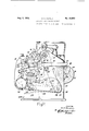
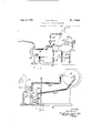
Fig. 1 is a front elevation of the machine of my invention,
Figure 2, an end elevation of said machine viewed from the right,
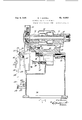
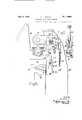
Fig. 3, a front elevation showing the relative position of the master cam and the cam shaft which is being ground,
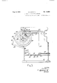
Fig. 4, a partial longitudinal section of the wheel base and the part of the bed on which it rests,
Fig. 5, an end elevation of the rear part of the bed viewed from the left and showing the wheel feeding motor,
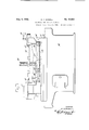
Fig. 6, an end elevation partly in section showing the piping for the wheel feeding motor as seen from the right in Fig. 1,
Fig. 7, a front elevation partly in section showing the oil pump and the piping to both the wheel feeding motor and the traverse motor,
Fig. 8, an end elevation of part of the traversing mechanism for the grinding wheel carriage,
Fig. 9, an elevation of the valve operating lever used on the carriage traversing mechanism, as seen from the left in Fig. 1,
Fig. 10, an elevation of a part of the mechanism for automatically controlling the movement of the wheel base, as seen from the left in Fig. 1,
Fig. 11, a horizontal section of said mechanism on line llll in Fig. 10,
Fig. 12, a front elevation of said mechanism,
Fig. 13, a right elevation of the foot stock,
Fig. 14, a. front elevation of said foot stock,
Fig. 15, a plan of said foot stock.
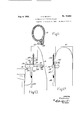
Fig. 16, a right elevation of the head stock partly in section showing the method of rotating the work and the master cam in unison.
Fig. 17, a right hand elevation of the head stock 10 illustrating means for swinging the work toward and away from the wheel so as to grind the cam to the desired shape,
Fig. 18, a longitudinal section of the head stock,
Fig. 19, a longitudinal section of the wheel 15 spindle showing means for reciprocating the same,
Fig. 20, a cross-section on line 2ll20 of Fig. 19,
Fig. 21, a detail of gearing shown in Fig. 19,
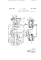
Fig. 22, a front elevation partly in section of 20 the valve for the traverse motor and the mechanism for operating said valve automatically to start and stop the traverse mechanism,
Fig. 23, a front elevation of the wheel feed motor, and
Fig. 24, a vertical longitudinal section of said motor.
In the drawings reference character 30 indicates the fixed bed of the machine which bed supports a work-carriage 3| mounted on guides 30 32 for reciprocation lengthwise of the machine. The bed also supports a slide base 33 pivoted near its front end at 34 for movement toward and from the work located on the carriage 3| in front of the slide base. The bed further supports a 35 fluid motor 35 by means of which the work carriage is moved to and fro on the guides 32, a wheel feed motor 36 for moving the slide base 33 on its fulcrum 34 and various driving and controlling mechanisms hereinafter described.
Work supporting and driving means The work carriage 3| bears a table 31 upon which a work supporting bracket 38 is mounted by pivots 39 for movement toward and from a 45 wheel 40 on a wheel base 4| slidingly supported on the slide base 33 for adjustment toward and from the work, as to set the wheel and to compensate for wear. The bracket 38 and parts carried thereby are roughly triangular in cross sec- 50 tion with the work 42 supported at one corner of the triangle, the master cam shaft 43 at another corner and the pivots 39 at the third corner. The position of the work is determined by a headstock 44 and a footstock 45 carrying respectively centers 45 and 47. The position of the master camshaft is determined by a coupling 48 at one end and a coupling 49 at the other end supported in the bearing 50.
Details of the headstock are shown in Figs. 16 to 18 together with driving means connecting the headstock spindle 5| to a crankshaft 52 which is connected by means of a lug 53 (Figs. 3 and 17) on the coupling 48 to the camshaft. The headstock spindle is driven by a sprocket 54 (Fig. 18) connected by a chain 55 to a sprocket 56 on the work drive shaft 51 (Figs. 1 and 2) which in turn is driven by a chain 58 from the change speed shaft 59 operated at various speeds by change speed gearing in a casing 68, the speed being varied by means of a hand-lever BI. The drive shaft of the change speed gearing carries a pulley E2 driven by a belt 63 from a work drive pulley 54 on the main shaft 65, and provided with a belt tightening idler 65. The headstock spindle is divided into two parts spaced from one another and provided with cranks 66 secured to the respective sections by means of dowel pins 51, said cranks carrying crank pins 68 fastened to the cranks by dowel pins 69. An intermediate crank 66 is secured to the adjacent ends of the firstnamed crank pins in similar manner. A work driver H1 is secured to the face plate of the inner spindle section adjacent the center 46.
The crankshaft 52 is provided with cranks and crankpins held together in similar manner to the parts described in connection with the spindle 5 I. Connecting rods II have bearings at opposite ends mounted on adjacent bearings of the crankpins, these connecting rods being arranged parallel to one another in well-known manner and serving to provide a smooth and uniform drive from the headstock spindle to the crankshaft 52 and hence to the master camshaft 43. It may be noted that the bracket 72 enclosing the crankshaft 52 and providing bearings for the same is separate from the main bracket 38 and secured thereto by dowel pins and bolts but this is uptional.
The footstock of the work-supporting mechanism is shown in detail in Figs. 13, 14, and 15. This iootstock comprises a center 41, a dust-cap 13, a tension nut I4 for the spring 15 pressing against the rear end of the spindle I6, a pinion TI having spur teeth meshing with rack teeth on the spindle, a pinion shaft 18 and a handle i9 by means of which the footstock center can be retracted for convenience in dismounting and replacing the work.
The master camshaft is provided with a series of cams corresponding in position to those on the camshaft to be ground while the whole camshaft to be ground may be provided only with roughly shaped cam blanks which must be ground down to suitable shape. For oscillating the brackets 38 to move the cam blanks toward and from the wheel during grinding operations I have provided a roller 89 mounted in fixed relation on a support secured to an upwardly projecting cover ill for the traverse motor which cover is fixed in relation to the base or bed 38. The bracket is forced upward by springs 82 (Figs. 1 and 2) into a position where one of the cams of the master camshaft will rest against the periphery of the roller 80. It will be clear from the foregoing that as the master camshaft rotates in synchronism with the camshaft being operated on the bracket 38 will be oscillated on its fulcrum 39 to move the work toward and from the grinding wheel in a manner to govern precisely the shaping of the successive cams. When the work on a cam is completed the carriage is caused to travel a sufiicient distance in one direction, e. g. to the left, to bring the next cam blank into operative relation to the wheel. For thus traversing the carriage I have provided a means comprising the fluid motor 35 of which certain details are shown in Figures 1 and 22 and which may be understood to be otherwise of any suitable type preferably having a vane mounted for oscillation between two fixed abutments in a chamber provided with means for admitting fluid alternately at opposite sides of the vane. The motor drives a shaft 83 carrying a pinion 84 whose teeth are in mesh with those of a rack 85 at the under side of the carriage.
Grinding wheel feed It will be recalled that the grinding wheel is carried by a. wheel base or wheel slide 4| mounted on a slide base 33 pivotally supported at 34. For the purpose of adjusting the wheel base along the slide base the slide base is provided with a rack 86 coacting with a pinion 81 on a vertical shaft in the wheel base and rotation of the vertical shaft causes the wheel base to move along guides 88, on the slide base. The wheel spindle 90 is journaled in bearings 9| on the wheel base 4| and the spindle is driven by means of a. pulley 92 over which passes a belt 93 driven by a pulley 94 on the main shaft 65. This belt is kept tight by an idle pulley 95 on a bracket pivoted at 34.
The wheel base and the slide base are tilted about their common axis 34 for moving the wheel toward the work to compensate for the decreasing diameter of the work by means comprising a roller 95 (Figs. 2 and 4) underneath the rear end of the slide base resting on a cam 91. The cam 91 is splined to the shaft 98 of the wheel feed motor. such motor being hereinafter referred to as the wheel feed motor. This motor has a vane 99 on the shaft 98 arranged for oscillation in a chamber containing an abutment I which limits the movement of the vane and through which abutment fluid may be admitted to move the vane in one direction or the other thus rotating the cam 91 correspondingly. A reversing lever Ifll controls the fluid admission valve I02 of the motor which may be any suitable type and is preferably slidable in a right line. A slide I03 (Fig. 24) is connected by a roller I04 and a pin I to the lever IOI for operating the valve. The pin also carries a roller I06 bearing on a detent H5 supported at opposite ends by springs I08 so as to force the lever II toward one or the other extreme of its movement. One purpose of this construction is to cause the wheel to retreat quickly from the work when a cam is finished.
Automatic controlling means In order that the traverse may be made without injury to the wheel or the work it is necessary that one or the other be moved so far from the other in a direction respectively forward or back as to avoid any danger of the work striking the wheel during the traverse. With this object in mind I have provided interconnected controlling means for the work carriage and the wheel feed including means adapted to act on a forward projection or roller bar I09 of the bracket 38 in a manner to impart an abnormal swinging movement to the bracket in a direction for retracting the work from the wheel. This mechanism is illustrated in detail in Figs. 4, 5 and 8 to 12.
A dog I Ill is mounted on the periphery of a dogwheel I l I and is adjustable about such periphery V the path of movement of the lever.
by means of a worm -I I2 having threads engaging teeth indicated at II 3 on the outer rim of the wheelf This dog is adapted to strike a lug H4 on the lever IBI, as the work feed motor moves clockwise in Fig. 5, for swinging the lever until the roller I05 passes the point of the detent II5 whereupon the springs immediately force the lever over the remainder of the path of its movement and reverse the motor. Under circumstances hereinafter described the lever IOI will be held from moving clockwise to the required extent for reversing the movement of the wheel feed motor by means comprising a stop H6 in The stop I I6 is adjustable longitudinally through a rockarm H1 and is provided with a lock nut H8 for looking it in adjusted position. The rockarm H1 is mounted on a rod H9 which is adapted to oscillate in bearings I20. At the front end of the rod II9 a rockarrn IZI is provided which rockarm is connected. by a link I22 to another rockarm I23 on a rockshaft I24 extending forward through the bed of the machine, or to the right in Fig. 5. At its forward end the shaft carries a rockarm I25 (Fig. 1) connected by a link I26 (Figs. 1, and 12) to a rack I21 adapted to engage a pin I26 on a rockarm I29 pivoted at I30 on a cover BI and provided at its forward end with a roller I3! contacting with the roller bar I09 (Figs. 10 and 22) at the front end of the bracket 38. A spring I32 draws the arm I 28 toward its uppermost position and a plunger I33 forced rearwardly by a spring 134 tends tomove the hook I35 into engagement with the pin I28 on said arm. A fixed abutment I36 (Figs. 10 and 12) on the cover SI has a cam face cooperating with a cam face at I31 on the hook I35 to disengage the same from the pin I28 when the parts are lifted sufliciently high by spring I32.
The dog-wheel III or other part moving therewith also carries a dog I38 adjustable about the periphery of the dog-wheel by a screw I38, said dog having a nose I35 pivoted at I40 for engagement with a lever I4I (Figs. 4 and 5) pivoted at I42. The dog I38 acts on said lever as the traverse motor moves In a clockwise direction (Fig. 5) to trip the parts operated by said lever the pivotal mounting of the nose permitting the dog to pass the lever in the contrary direction of move- -ment of the traverse motor without changing its position. As here shown the dog moves from the solid line position of Fig. 5 to the dotted line position. The lever MI is connected by a link I42 to a lever I63 pivoted at IM and this in turn is adjustably connected at 45 to a rod I46 slidably mounted in a bearing I61 and carrying a collar I48. A spring I49 surrounds the rod said spring bearing at one end against collar I48 and at the other against bearing I41 and serving to move the rod and the partsconnected therewith normally to the right in Fig. 5 or toward the front of the machine. At its forward end the rod I46 is connected by suitable means such as a bent lever to an upright rod I55 (Figs. 1 and 8) which in turn is connected at its upper end by a bent lever I5I pivoted at I52 to a slidable detent I53 impelled by a spring E54 in a direction to engage under a lateral arm of a lever I55 (Fig. 22).
The piston I56 is slidably mounted in a cylinder I51 formed in the cover BI and is provided at its lower end with a roller I58 engaging the upper face of the roller bracket I69. At its upper end the chamber I51 has a single port I59 opening into a valve chamber provided with an inlet port I60 (Figs. 1 and. 22) and an exhaust port IBI. A
balanced piston valve I62 is located in said valve chamber and said valve has a stem I63 adjustably connected to the lever I55 with provision for lost motion. The lever I55 has a vertical arm and a laterally extending inclined arm provided at its outer end with a roller I58. A double-acting spring-pressed plunger I65 is mounted approximately in line with said arm so as to force the lever toward its extreme position in either direction of its movement. It will be seen that the detent I53 and the plunger 165 will hold the lever I55 and the valve I62 in the position indicated, so that piston I55 will not move until the detent I53 is retracted. When this occurs the plunger I65 will force the roller I64 downward and move the valve so as to connect the port I59 to the inlet port I66 whereupon the fluid will enter the piston chamber and force the piston down thereby moving the bar I09 downward to tilt the work supporting bracket 38 away from the wheel.
It will be recalled that the work carriage has a step-by-stcp or intermittent traversing move ment for moving the camshaft so as to bring its successive cam blanks into the field of operation of the grinding wheel 40 and such movement is availed of for the purpose of returning the work carriage bracket to working position. For this purpose the traversing roller bar is provided with dogs I66 having forwardly projecting lugs I61 (Figs. 8, 9 and 22). The lever I55 is also provided with 9. depending finger I69 terminating in a rearwardly projecting lug I68 adapted to cooperate with the lugs I61 in one position thereof (Fig. 9). The finger I66 is pivoted on the lever at I10 in such a manner as to swing to one side in one relative direction of movement of the roller bar and the lever thus avoiding injury to the relatively movable parts. A pin I1I limits the swinging movement of the linger in a counterclockwise direction. The lever I55 has a rockarm I12 pivoted thereon, with a roller I13 adapted to contact with the roller bar I09 as it rises. A spring I14 provides a yielding connection between the rockarm I12 and a rigid finger I15, thus cushioning the action of the roller bar on the lever and the valve I62.
It will be seen from the foregoing that when the detent I53 is withdrawn the lever I55 will be moved clockwise by the plunger I65 so as to open the intake passage I66 to the chamber I51 and thus force the bar down so as to bring its lugs I61 to the level of the lug I68 on the finger I69. As bar I09 now moves to the right in Figure 22 with the work carriage, the appropriate lug I61 will strike the lug I68 (it being understood that the number of dogs I66 corresponds to the number of cam blanks on the cam shaft 62). The movement of the carriage will now cause the lever to swing on its pivot in a counterclockwise direction and this will move the balanced valve so as to shut oil the intake port I60 from the port 559 and open a passage from outlet port I6I to port I59. At the same time the spring-pressed plunger I65 is permitted to return into holding position relative to the lever The movements above described, initiated by engagement of dog I38 with lever MI in Figure 5 are utilized to govern the operation of the traverse motor. When the bar I59 is forced down by the pressure in the cylinder I51 it acts on a roller I16 (Figs. 8 and 22) on a roller bracket I11 provided with a handle I18. The roller bar is supported on a plunger I19 guided for up and down movement in a plunger bracket I80 on the cover M, the movement of the plunger being limited by a stop I8I engaging at its inner end in a slot having parallel vertical branches I8I connected by a. horizontal cross-over portion. At its lower end the plunger bears on a laterally extending arm I82 of a three-armed lever I83, the lowermost arm of which is connected to the stem I84 of a balanced piston I85 in a chamber I88 which piston controls the operation of the oscillatory traverse motor 35. It has not been deemed necessary to illustrate details of this motor as it is of well-known type and is shown in other pending applications.
As the roller bar I89 pushes the plunger I19 down and. moves the lever I83 counterclockwise the valve I85 uncovers a port I81 leading to an expansion chamber at one side of the vane of the traverse motor and admits fluid under pressure through an intake port I88 to said expansion chamber. Such movement of the valve also opens a passage from the port I89 to the outlet passage I98 of the motor for escape of fluid from the non-working side of the motor. The contrary movement of the roller bar and plunger permits a spring I9I to move the lever I83 in a clockwise direction thus moving the valve I85 to the left to an extent sufficient only to bring the valve into the position illustrated in Figure 22 where the entrance of liquid to either side of the motor, i. e., to either of its two opposed expansion chambers, is prevented and thus any traversing movement of the carriage during grinding is prevented.
When an entire camshaft has been completed and has been replaced by a new one the carriage must be returned to its original or starting position and for this purpose the handle I18 is turned to the left sufficiently to disengage the pin I8I from the shoulder between the branches I8I' of the slot in which the pin moves. The plunger I19 may now rise to the full extent of its movement and the lever I83 may consequently be moved in a counter-clockwise direction by the spring I9I to such an extent as to open a passage from the inlet port I92 to the port I89 for moving the motor in a direction to return the work carriage to its original position. At the same time the valve opens a way from the port I81 to the outlet I98 to permit escape of fluid from the nonworking side of the traverse motor.
Pump
The device of my invention is provided with a rotary pump I93 driven by a sprocket chain I94 passing over a sprocket I95 on the pump shaft and a sprocket I96 on the main shaft of the machine. The pump has an intake I91 and a pipe i98 communicating with the inlet ports I88 and I92 of the traverse motor and also with the inlet port I68 for the piston chamber I51. An exhaust pipe 93 returns the exhaust fluid from the ports E39 and I81 of the traverse motor and a pipe I99 returns exhaust fluid from the exhaust port IBI of the piston chamber to the reservoir 288 at the bottom of the machine. A manually operated valve indicated at 285 in Fig. 1 serves to vary the supply of pressure fluid to the traverse motor when desired. A pipe 282 leads from the pipe I98 to the wheel feed motor 38 and an exhaust pipe 283 brings back the exhaust fluid from said motor to the reservoir 298. A valve 284 is normally spring-pressed to closed position. This valve provides a means whereby the operator can permit the fluid to return temporarily to the reservoir without operating the motor and the valve may also provide for relief of excessive pressure so that the speed of the pump need not be changed, nor need the pump be stopped because of temporary cessation of the operation of the machine. The valve is opened by the operator through the aid of the lever 22 I.
Wheel traverse It is found desirable to give a limited traverse to the grinding wheel for reducing the wear on the wheel as much as possible and to give a smooth even finish to the work. For this purpose the grinding wheel spindle 98 is provided with a worm 286 meshing with teeth on a pinion 281 which is loose on a shaft 288. The shaft has eccentric portions at each end engaging forks in levers 289 pivoted at 2). These levers are connected by means of links 2 to a bronze collar 2I2 surrounding the shaft, said forks being pivoted to the collar at 2I3. The collar is held against endwise movement on the shaft by means of a pair of washers 2I4, the washer at the left resting against a shoulder on the spindle and the washer at the right being held in place by a nut 2E5. The gear 281 is caused to rotate with the shaft 288 by means of a clutch member 2H5 engaging a clutch face on the gear. A coiled spring 2 tends to separate the clutch faces and a screw 2I8 having an outer hand wheel 2I9 bears at its inner end against a pin 228 which is mounted at its ends in the clutch member 2 I 8 so that rotation of the hand wheel moves said clutch member into engagement with the worm gear.
It will be seen that rotation of the spindle and the wheel will turn the worm gear 281 and the eccentrics rotating therewith thus swinging the levers 289 through their connections to the collar 2 I2 moving the shaft endwise to a limited extent. This reciprocating motion may be stopped by separating the clutch member 2I8 from the worm gear through the medium of the hand wheel 2I9 and screw 2 I8.
Operation In the operation of my device a camshaft is placed between the work centers, as indicated in Figure 3, the work carriage having been previously brought to its position farthest to the right so as to begin operations on a cam blank. The starting lever 22I is now moved to the right to open the valve 284 and fluid under pressure passes to the traverse motor, power being also applied to the wheel in ordinary manner. The wheel feed motor rotates the cam 91 in a counter-clockwise direction as seen in Figure 5, or clockwise as seen in Figure 2, the headstock is driven as above described causing the bracket 38 to rock in accordance with the contour of the master cam on the camshaft 43 and the operation proceeds in ordinary manner until the cam is ground to the desired size at which time the dog I38 strikes the pin II4 on lever IM and swings the lever in a counterclockwise direction to a position in which the upper end of the lever moves to the left of the position shown in Figure 5.
This shifting of the lever IN to the left, as referred to above, positions the valve I82 so as to admit fluid to that side of the wheel feed motor, which will cause the motor to turn clockwise; that is, in a direction to lower the feed slide. The work carriage is now indexed and shifted to position the work for grinding the next cam. The clockwise movement of the wheel feed motor will cause the dog I38 to move from the dotted line position in a counterclockwise direction to the full line position Where it will shift the lever IM and again reverse the" valve which reverses the motor and moves the grinding wheel away from the work. The pivoted end portion I39 of the dog permits the dog to pass the nose of the trip lever I4I without moving the same.
On the reverse movement of the motor the dog wheel is moved clockwise and such movement continues until dog IIO strikes pin H6 and moves lever IM to the position indicated in solid lines in Figure 5 where it abuts against a stop II6 which prevents further movement of the lever for the time being and cuts off the fluid from both sides of the motor. Just prior to the attainment of this position by the dog H0, the dog I38 passed the nose of lever I 4| in a clockwise direction and therefore moved said lever about its pivot I42. As a result of such movement the lever MI acting through the train of connections M2, I63, I46, I50 and I5I retracts the latch I53 from lever I55 (Fig. 22). Thereupon the plunger I65 acts on the lever through the roller I64 to move the valve I62 to the right and permit pressure fluid to enter the cylinder I51, moving piston I56 so as to force roller bar I05 down and so set the traverse motor in operation to index the carriage by acting on arm I82 of lever I63. The lateral movement of the bar with the work carriage causes the next lug I61, which has now been lowered to the proper level, to strike lug I68 and tilt lever I55 out of the way of latch I53 which then is moved back to latching position by spring I54. At the same time the lever moves the valve I62 to stop the flow of pressure fluid and opens the way to outlet I6l, thus permitting the piston I56 and the bar I09 to rise. As the bar rises the spring IBI moves the lever I83 and valve I65 so as to stop the traverse motor.
When the bar I09 is forced down it acts through roller I3I to lower lever I29 until pin I28 is low enough to be engaged by hook I35, when the hook is moved into engagement with said pin. As the bar rises the rod I26 is moved up and through the train of elements previously described, rocks shaft H9 to move stop H6 out of the way of lever IOI whereupon the lever moves further over under the pressure of detent H5 until it is in position to cause the motor to move in a clockwise direction to again raise the slide base and so repeat the cycle of operations. Thus the wheel cannot be moved toward the work until the traverse movement is completed.
It will be obvious to those skilled in the art that various changes may be made in my device without departing from the spirit of the invention, and I, therefore, do not limit myself to what is shown in the drawings and described in the specification, but only as set forth in the appended claims.
Having thus fully described my said invention, what I claim as new and desire to secure by Letters Patent, is:
1. In a cam grinding machine, a rotary wheel, a tilting support therefor, a bracket tiltable on an axis parallel to that of the wheel, means on said bracket for supporting a camshaft, and means including a master camshaft for tilting said bracket, and means for tilting said bracket away from the grinding wheel, substantially as set forth.
2. In a cam grinding machine, a rotary wheel, a tilting support therefor, a bracket tiltable on an axis parallel to that of the wheel, means on said bracket for supporting a camshaft, a master camshaft arranged parallel to the axis of said wheel, and a fixed follower on a fixed support coacting with the cams on the master camshaft for tilting the bracket, and means for tilting the said bracket away from the ginding wheel, substantially as set forth.
3. In a cam grinding machine, a rotary wheel, a tilting support therefor, a bracket tiltable on an axis parallel to that of the wheel, means on said bracket for supporting a camshaft, a master camshaft arranged parallel to the axis of said wheel, a follower on a fixed support coacting with the cams on the master camshaft for tilting the bracket, and resilient means serving to tilt the bracket and move the work toward the wheel, and additional means for tilting the bracket away from the grinding wheel, substantially as set forth.
4. In a cam grinding machine, a rotary wheel, a tilting support therefor, a work carriage, means on the carriage for supporting and rotating a camshaft, a cam for tilting the wheel supporting means, and an oscillatory fluid motor for driving said cam alternately in opposite directions, substantially as set forth.
5. In a cam grinding machine, a rotary wheel, a tilting support therefor, a work carriage, means on the carriage for supporting and rotating a camshaft, a cam for tilting the wheel supporting means, an oscillatory fluid motor for driving said cam alternately in opposite directions, a traversing work carriage, and means for moving with said motor for controlling the movements of the work carriage, substantially as set forth.
6. In a cam grinding machine, a rotary wheel, a tilting support therefor, a work carriage, means on the carriage for supporting and rotating a camshaft, a cam for tilting the wheel supporting means, an oscillatory fluid motor for driving said cam alternately in opposite directions, a travers ing work carriage, means for moving the work carriage step-by-step to bring successive cams into the field of operation of the wheel, and means operated by said fluid motor for controlling the step-by-step movements of the carriage, substantially as set forth.
7. In a cam grinding machine, a rotary wheel, a tilting support therefor, a work carriage, means on the carriage for supporting and rotating a camshaft, a cam for tilting the wheel supporting means, an oscillatory fluid motor for driving said cam alternately in opposite directions, a traversing work carriage, a fluid motor for operating said carriage, and means operated by said first-named fluid motor for setting the second fluid motor in action at intervals to move the carriage intermittently in one direction, substantially as set forth.
8. In a cam grinding machine, a rotary wheel, a tilting support therefor, a. work carriage, means on the carriage for supporting and rotating a camshaft, a cam for tilting the wheel supporting means, an oscillatory fluid motor for driving said cam alternately in opposite directions, a traversing work carriage, an oscillatory fluid motor for operating said carriage, and means controlled by the first-named fluid motor for putting the second-named fluid motor into and out of operation to move the carriage step-by-step in one direction, substantially as set forth.
9. A cam grinding machine comprising a rotary wheel, a traversing work carriage, a tilting bracket on the work carriage, means for moving the carriage intermittently to bring successive cams into the field of operation of said wheel, and means for tilting the bracket to prevent interference with said traversing movement including a fluid motor, substantially as set forth.
10. A cam grinding machine comprising s. rotary wheel, a traversing work carriage, a tilting bracket on the work carriage, means for moving the carriage intermittently to bring successive cams into the field of operation of said wheel, means for tilting the bracket to prevent interference with said traversing movement includin a fluid motor, wheel feeding means including a fluid motor, and means operated by the wheel feeding means in the extreme forward position of the wheel for setting the first-named fluid motor in action, substantially as set forth.
11. A cam grinding machine comprising a rotary wheel, a traversing work carriage, a tilting bracket on the work carriage, means for moving the carriage intermittently to bring successive cams into the field of operation of said wheel, means for tilting the bracket to prevent interference with said traversing movement including a fluid motor, wheel feeding means including a fluid motor, means operated by the wheel feeding means in the extreme forward position of the wheel for setting the first-named fluid motor in action, and automatic means for putting said motor out of action for a predetermined traverse of the work carriage, substantially as set forth.
12. In a cam grinding machine, a rotary wheel, a tilting support therefor, a work carriage, means on the carriage for supporting and rotating a camshaft, a cam for tilting the wheel supporting means, a fluid motor for driving said cam alternately in opposite directions, a traversing work carriage, means for moving the work carriage step-by-step to bring successive cams into the field of operation of the wheel, means ope ated by said fluid motor for controlling the step-bystep movements of the carriage, the said means comprising a, reversing valve for said fluid motor, a bar mounted on said carriage, dogs adjustably secured to said bar, an arm operable by said dogs, and a valve movable to exhaust position by said arm whereby said reversing valve is permitted to return to inoperative position, substantially as set forth.
13. In a cam grinding machine, a rotary wheel, a tilting support therefor, a work carriage, means on the carriage for supporting and rotating a camshaft, a cam for tilting the wheel supporting means, a fluid motor for driving said cam alternately in opposite directions, a traversing work carriage, means for moving the work carriage step-by-step to bring successive cams into the field of operation of the wheel, means operated by said fluid motor for controlling the step-bystep movements of the carriage, the said means comprising a bar mounted on said carriage, dogs adiustably secured to said bar, a reversing valve, and operative connection between said dogs and said reversing valve to permit the return of said valve to inoperative position, substantially as set forth.
14. In a cam grinding machine, a rotary wheel, a tilting support therefor, a work carriage, means on the carriage for supporting and rotating a camshaft, a cam for tilting the wheel supporting means, a fluid motor for driving said cam alternately in opposite directions, a traversing work carriage, a fluid motor for operating said carriage, means operated by said first-named fluid motor for setting the second fluid motor in action at intervals to move the carriage intermittently in one direction, the said means comprising a dog wheel, an irreversible dog on said dog wheel, a retaining pin, operative connection between the said dog and the said retaining pin, the said operative connection being adapted to withdraw the retaining pin when the motor operates in one direction, a valve operating arm held in position by said pin, a spring pressed plunger for operating the said arm, a valve controlled by said arm, a piston operated by said valve, and a reversing valzle operated by said piston, substantially as set for h.
15. In a cam grinding machine, a rotary wheel, a support therefor, a bracket tiltable on an axis parallel to that of the wheel, means on said bracket for supporting a camshaft, a master camshaft arranged parallel to the axis of said wheel, and a fixed follower on a fixed support coacting with the cams on the master camshaft for tilting the bracket, and means controlled by movement of the wheel support to its rearmost position for tilting the said bracket away from the grinding wheel, substantially as set forth.
16. In a cam grinding machine, a rotary wheel, a movable support therefor, a work carriage, means on the carriage for supporting and rotating a camshaft, a cam for moving the wheel sup-- porting means, a fluid motor for driving said cam alternately in opposite directions, a traversing work carriage, and means moving with said motor for controlling the movements of the work carriage, substantially as set forth.
17. In a cam grinding machine, a rotary wheel, a movable support therefor, a work carriage, means on the carriage for supporting and rotating a cam shaft, a cam for moving the wheel supporting means, a fluid motor for driving said cam alternately in opposite directions, a traversing work carriage, means for moving the work carriage step-by-step to bring successive cams into the field of operation of the wheel, and means operated by said fluid motor for controlling the step-by-step movements of the carriage, substantially as set forth.
18. In a cam grinding machine, a rotary wheel, a movable support therefor, a work carriage, means on the carriage for supporting and rotating a camshaft, a cam for moving the wheel supporting means, a motor for driving said cam alternately in opposite directions, a traversing work carriage, a fluid motor for operating said carriage, and means operated by said first-named motor for setting the said fluid motor in action at intervals to move the carriage intermittently in one direction, substantially as set forth.
19. A cam grinding machine comprising a grinding wheel, a support therefor, a work carriage, automatically operable means for moving the carriage intermittently to bring successive cams into the field of operation of said wheel, a bracket tiltable on an axis parallel to that of the wheel, means on said bracket for supporting a camshaft, a master camshaft for tilting said bracket, and means for moving said wheel support toward the work, substantially as set forth.
20. A cam grinding apparatus comprising a grinding wheel and a cam blank support which are relatively movable towards and from each other, means including master cams to cause said relative movement to produce desired contours on various cam blanks, means to cause relative traversing movement between the wheel and cam blanks to position the wheel in operative relation with a given cam blank, and means to separate the wheel and the cam blank support before a new cam may be located in position opposite to the wheel.
Publications (1)
| Publication Number | Publication Date |
|---|---|
| USRE19663E true USRE19663E (en) | 1935-08-06 |
Family
ID=2083962
Family Applications (1)
| Application Number | Title | Priority Date | Filing Date |
|---|---|---|---|
| US19663D Expired USRE19663E (en) | Automatic cam grinding machine |
Country Status (1)
| Country | Link |
|---|---|
| US (1) | USRE19663E (en) |
-
0
- US US19663D patent/USRE19663E/en not_active Expired
Similar Documents
| Publication | Publication Date | Title |
|---|---|---|
| US2127210A (en) | Grinding and lapping machine | |
| US1899654A (en) | Worm grinding machine | |
| US2264160A (en) | Grinding machine | |
| US2078749A (en) | Hydraulically operated grinding machine | |
| US2648171A (en) | Multiple wheel grinding machine | |
| US1725489A (en) | Island | |
| US2387166A (en) | Automatic gear grinding machine | |
| US1714545A (en) | Fluid-pressure controlling and reversing mechanism for grinding machines and the like | |
| USRE19663E (en) | Automatic cam grinding machine | |
| US2243405A (en) | Feeding mechanism | |
| US2080976A (en) | Hydraulically operated surface grinding machine | |
| US2224959A (en) | Cutter sharpener | |
| US1675466A (en) | Automatic cam-grinding machine | |
| US2131939A (en) | Production tap grinder | |
| US2022061A (en) | Gear grinder | |
| US2477733A (en) | Grinding machine | |
| US2453678A (en) | Cylindrical grinding machine | |
| US2029510A (en) | Hydraulic ball race grinder | |
| US1987222A (en) | Apparatus for grinding discontinuous segmental surfaces | |
| US2156970A (en) | Grinding machine | |
| US2012065A (en) | Grinding machine | |
| US2088746A (en) | Metal bending machine | |
| US2710495A (en) | Cam grinding machine | |
| US2572529A (en) | Grinding machine | |
| US2163246A (en) | Grinding machine |