USRE14404E - Doing business - Google Patents
Doing business Download PDFInfo
- Publication number
- USRE14404E USRE14404E US RE14404 E USRE14404 E US RE14404E
- Authority
- US
- United States
- Prior art keywords
- handle
- truck
- frame
- cams
- swivel
- Prior art date
Links
- 230000003028 elevating Effects 0.000 description 40
- 230000023298 conjugation with cellular fusion Effects 0.000 description 16
- 230000013011 mating Effects 0.000 description 16
- 230000021037 unidirectional conjugation Effects 0.000 description 16
- 230000000875 corresponding Effects 0.000 description 12
- 238000010276 construction Methods 0.000 description 8
- 230000000994 depressed Effects 0.000 description 8
- 230000000881 depressing Effects 0.000 description 4
- 238000000034 method Methods 0.000 description 4
- 238000000926 separation method Methods 0.000 description 4
- 229940109526 Ery Drugs 0.000 description 2
- 241000275031 Nica Species 0.000 description 2
- 208000002193 Pain Diseases 0.000 description 2
- 239000011449 brick Substances 0.000 description 2
- 101700032944 corto Proteins 0.000 description 2
- 238000007689 inspection Methods 0.000 description 2
- 230000004048 modification Effects 0.000 description 2
- 238000006011 modification reaction Methods 0.000 description 2
- 230000036407 pain Effects 0.000 description 2
- 108060008687 tus Proteins 0.000 description 2
Images

Definitions
- This invention relates to an elevating truck.
- Devices of this kind are well-known in the art and comprise, in general, a three or four wheeled truck rovi ed with a base and a latform capab e of being raised or elevate away from the base in order that, thmtruckfniay be wheeled underneath a load of brick, or what not, upon a suit- Per abl the platform elevated, picking the load then wheeled away. ucklof, t
- the steerin handlel'ipreferab yy -indirectly connecte with two front-wheels which are all caster formand instead of being mounted upon the same axle, are4 .turned on their vertical pivots inthe' lower platform .or base portion of the the elevating mechanisms of my new and improved truck have been so constructed and arranged that' it is entirely immaterial' in what direction the handle happens to be pointing at the time it is depressed for raisingthe platform; the platform going up exactly as well whatever/the position ofthe handle.
- his saine mechanism o erates in precisely the same manner when t e truck is t0 be depressed, theflifting devices as they are operated to lower the truck automatically locking after each slight movement in a downward direction. This I consider broadly new.
- Another important feature of the invention comprises the arrangement whereby I make use offtwosuperposed and mutually engagin cal stan point) that I have been enabled to double the lift of the platform without materially increasing the minimum height of the platform from the floor.
- Another advantage inlierent tothe arrangement resides in the fact that the platform, while being raised has no longitudinal cams which means (from a practi..
- a 'Another feature of my invention resides 1n the construction and arrangement whereby without the use of p'awl-and-ratchet mechanisms or their equivalents the handle may, if desired, be operated successively a plurality of ⁇ times in the same vertical arc while raising a load on the platform.4
- This is an important advantage, for my truck is especially designed to raise heavy loads, and the arrangement permits the operator to opt erate the handle a plurality hlm a purchase not possible vwere it necessary for him to raise the platform by following through one depressing movement of the handle from a substantially vertical to a substantially horizontal position.
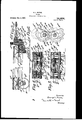
- FIG. 1 is a top, plan ⁇ view of my improved truck.
- Fig. ⁇ 2 is a side view.
- Fig. 3 is a longitudinal cross-section 4 is Fig.
- Fig. 5 is a cross-section taken on 5-5 of Fig. l; and Fig. 6 is a detail view on a larger scale illustrating the cam lifting device forming an important feature of my invention.
- My truck comprises a. frame and a platform A and B, frame A being supported uponthe rearwheels a and having swiveled front wheels a.
- Platform B is adapted by mechanism hereinafter to be described to be raised from frame A and away from the same.
- Frame A carries brackets A by which it is supported from the axle of the rear wheels of the truck in an old and familiar manner.
- a vertical bearing D carrying a sleeve member d provided with a pair of arms d at its upper end and a downwardly-projecting integral segmental boss d2 at its lower end. Between the arms d is mounted a shaft d and on this shaft is, in turn, mounted a pair of toothed wheels d.
- the mechanism illustrated in Fig. 6 is worthy of a detailed description.
- the cams e* are provided with a series of circular bosses e" while the cams es. are provided with a corresponding series of circular recesses e6. Between ⁇ these bosses e4 are flat portions e, and. between thecircular recesses @6 are flat portions e, these portions lying in the tangential plane of the cam at the points at which they occur.
- the rack f engages at its other end a pinion f* secured to the rear axle f5 of thel truck.
- This rear axle is supported on bearings formed integrally with the frame A and carries wheels a.
- the rack f is held in contact with pinion f* by a roller f7 carried on a web-f depending from frame A, asV
- Fig. 5 Depending from platform B are a Pair of brackets g and g2 supporting la sha t g3, which shaft carries cams g* coperating with cams g5 upon shaft f", precisely as the cams e* coperate with the cams e in the mechanism heretofore described. These cams g and g*s are provided also with a pair of slotted bars carrying pins precisely as illustrated in Fig. 6 and described in connection with the mechanism at the front end of the truck. Depending from the platform B are brackets B at either side of the rear 'ends thereof and brackets E3 at either side of the front thereof.
- brackets carry rollers at" the rear' end and k at the front end, which rollers are engaged in slots in the brackets A and E on frame A, in order to prevent the upper platform B from having longitudinal movement with A.
- U on op osite sides of the front of the lower ame are mounted by a well-known ball-bearing spiport, as shown in Fig. 2, casters H and I carrying the front wheels 'a' of the truck.
- These casters are connected through the intermediar1 of lugs La with radius rods h4, which ro s are, in turn, connected at their lower ends to depending circular boss d2 on the member d.
- the truck may be steered by its handle d2 'radial movement of the handle d in a horizontal direction being communicated through the'bearing d to ⁇ the radius rods h* and thus to the individual casters on the front of the frame.
- a lifting truck,l a base, mounted in said base, a cylindrical rack .carried by the swivel, a steering handle carried by the swivel, and means associated with f the handle for the operation of the rack.
- a lifting truck comprising, in combination, a frame,a movable platform, a plurality of cams rotatably mounted on the frame, a plurality of cams rotatably mounted on the platform and engageable with the ⁇ irstnamed cams, whereby aA series of lifting devices arranged in pairs is provided, and means operable to turn one cam of each pair having its periphery ⁇ formed with a Vseries of spaced recesses, the other cam of each pair having its periphery formed with a series of spaced rojections engageable in said recesses, w yereby one cam of each pair may be rotated by the other, all constructed and arranged so that normally two projections of one cam engage with two recesses of the mating camson opposite sides of the line of centers of a pair -of cams and so that as any projection with its mating recess ⁇ crosses said line of centers, the said centers are forced farther apart than immediatelybefore or after such positioning, whereby the .liftin
- a lifting truck comprising, in combination, a wheeled frame, a movable platform, a plurality of cams carried by ⁇ the frame, a ⁇ plurality of cams carried' by the platform and engageable with the first named cams, whereby a series of 4lifting devices arranged in pairs is provided, a steering handle mounted on the frame, and means operable from said handle to turn one cam of'each air, one cam of each pair havin its perip ery formed with a seriesfof space recesses,gthe other cam of each pair having its periphery formed'with a series of spaced projections engageable in said recesses, wherebyfone cam of ea'ch pair may be ro- .tated by the other, all constructed and arranged so that normally two projections of one cam engage with two recesses of the mating cam yon opposite'sides of the line of centers of a pair of-cams and so that -as any projection with its mating recess crosses said 'line of centers,
- a lifting truck comprising, in combination, a base portion, a liftingy platform, a 70l steering handle swiveled in the base portion, lifting devices-arranged between the platform and base portion, each device comprising a pair of separate but mutually engaged rotatable members, operative connections between said devices and said handle, whereby l upondepression of the latter the liftin devices may be actuated to lift the plat orm, one member of each pair having its periphery formed with a series of spaced recesses, the other member of each pair having its periphery formed with a series of spaced projections engageable in said recesses, where-X by ⁇ one member of each pair may be rotated by the other, all constructed and arranged so that normally two projections of one meml mating member on opposite sides of the line of centers of a pair of members and'so that as any projection with its mating recess crosses said ,j
- a steering handle connected to the swivel, means associated with the handle independently movable therein at the will of the operator and arranged to operatesaid pinion, lifting devices between the frame ⁇ and plat- 105 form, each device comprisin a pair of separate but mutually engage members, and meansoperable from said rackto actuate one member ofl each pair, one member of each pair having its periphery formed with a series of spacedrecesses, the other member of each pair having its periphery formed with a series of spaced projections engageablein said recesses, lwhereby one member of each pair may be -rotated by'the other, all con-,1,15 structed and arranged so thatnormally two projections of one member engage with two recesses of the mating member on opposite j sides of the line of centers of a pair of members and so that as 'any projection with its 120 mating recess crosses said line of centers, the said centers are forcedfarther apart ⁇ than immediately before or after such positioning, ⁇ wherebythe
- an elevating truck the combination with a frame and supporting and steering wheels, of a steering swivel, a steeng handle fulcrumed upon said swivel elevating mechanism on said frame an means for operating said elevating mechanism from said handle in any steerin position of ysaid handle, comprising in ividually.
- an elevating truck the combination with a frame and supporting and steering wheels, handle fulcrumed upon said swivel, elevating mechanism on said frame and means for operating said elevating mechanism from said handle comprising a member connected with said handle and movable handle both in its steering and in its swinging movements, a second member pivoted on the frame, and a constant positive connection between said members upon which one member is movable relatively to the other about the axis of said swivel, said connection being arranged to reciprocate in the line of said axis.
- an elevatin truck the combination with a ramean supporting and steer- Y in wheels, of a steering swivel at the front o said frame, a steering handle pivotally connected to said swivel, and elevating mechanism comprising a member ivoted on said frame and having av connection to said handle comprising a line of the axis of said swivel, said connection having ment of said andle and said pivoted member about the axis of said swivel.
- a liftin ,truck comprising a base member movable in the provision for relative moveof said frame, a steerin handle 'fiulcrumed upon s aid swivel, and e evating iii'echanisin comprising a member pivoted on said frame and a connection between said handle and said member by which a movement of said handle in either direction about its ulcrum may be transmitted to said member said connection having a swivel whereby said vhandle may operate said elevating mechanism in any position ofsaid handle.
- a steering handle in combination with the truck frame and they supporting and steering wheels, a steering handle, a steering swivel ii on which said handle is fulcrumed, and e evating mechanism comprising a member pivoted upon said frame and having a connection to said handle comprising a part movable in the line of the axis of said swivel, said member and said handle bein relatively movable upon said connection a ut said axis.
- an elevating truck the combination with a frame andl supporting and steering wheels, of a steering swivel, a steering handle ulcrumed' on said swivel, elevating mechanism comprising a movable member mounted on the frame, and means for tivel transmitting the movements o the ulcrum to said movable member without transmitting the steering movements of said handle, said means comprising a connection having provision for a. swiveling relative movement of said members about the axis of said swivel.
- a steering handle fulcrumed on said swivel elevating mechanism comprising a vmovable member mounted on the frame, and means for osi.- tivel transmittn the movements o the han e about its ulcrum to4 saidmovable member without transmitting the steering movements of said handle,'said means comprising a part' arran ed to transmit the power applied to said andle along the axis of ,said swivel and about which said memmovable on said axis.
Description
G. L. MASON.
TRUCK.
APPLICATION min ocT. 5. |911.
M.. Am 4S. 1m
Reissued Dem/1, 1917.
guwnto/c Gem-cse' Maen,-
@ttor/nuja' G. L. MASON.
TRUCK.
APPucmou mio ocr. 5. m1.
Bissued Dec. 4, 1917.
@mm1/woz Geovcst L. Msum @Romanas essaryl to i straiglitaliead.'
all.
" truck. Moreover,
genera d le is pulledl down,
vated, but these devices have all been ob- GEORGE L. MASON,
ASSIGNMENTS, T0 HERBERT W.
N. WHITE, TaUs'rnEs, 'ALL or HoLY AS COWAN TRUCK COIDANNY.
0l' WAREHOUSE POINT, CONNECTICUT, ASSIGNOR, BY MESNE COWAN, J. LEWIS WYCKOFF, AND EDWARD OKE, MASSACHUSETTS, DOING BUSINESS TRUCK.
Specification of Beissued Letters Patent. Reigsuedqngc, 4, 1917.
0rlg'lnal No. 1,178,684, dated March 21, 1916, Serial No. 768,912,71lled Hayil, 1913. Application tor reissue nica october 5, 1917. seriaito. 194,931.
' This invention relates to an elevating truck. Devices of this kind are well-known in the art and comprise, in general, a three or four wheeled truck rovi ed with a base and a latform capab e of being raised or elevate away from the base in order that, thmtruckfniay be wheeled underneath a load of brick, or what not, upon a suit- Per abl the platform elevated, picking the load then wheeled away. ucklof, t
character heretofore manufacturemjn so far as I have been aware,
lly comprise a steering handle directl associated with the front wheel or wliee s whichare mounted upon the same axle and'mechanis'm whereby, when the hanthe platform may be elejectionable for the reason that, before the platform can'. be elevated, it has been necpoint the handle substantially In a trnckconstructei on the other hand,
invention, the steerin handlel'ipreferab yy -indirectly connecte with two front-wheels which are all caster formand instead of being mounted upon the same axle, are4 .turned on their vertical pivots inthe' lower platform .or base portion of the the elevating mechanisms of my new and improved truck have been so constructed and arranged that' it is entirely immaterial' in what direction the handle happens to be pointing at the time it is depressed for raisingthe platform; the platform going up exactly as well whatever/the position ofthe handle.
Trucks constructed according to the old practice, in so far as I am aware, furthermore been objectionable and faulty on mechanical principle, the elevating devices for the lplatformhave been so arranged that they ta e their move-` ment corresponding throughout Vto the depressing movement of the handle.
the following is a specifor the reason that handle is further depressed, thereby giving' an easy start. This makes the entire operation of the device correct on mechanical theory and much more eiicient in practical operation.
Besides these features which I have been at' pains to particularly oint out as comprising important parts o my invention and which I consider both useful and broadly new, I desire at this point to call attention to another feature wherein my truck is both useful and novel. This relates to an automatic self-locking arrangement whereby the platform, by the construction and arrangement of the elevating devices'themselves as distinguished fromthe operatingmechanism therefor, is locked at closely consequentsuccessive points throughout its entire lifting movement, the lift of solvin itself into a series of short lifts after eac vone of which the truck is locked in osition and cannot be depressed by the load.
his saine mechanism o erates in precisely the same manner when t e truck is t0 be depressed, theflifting devices as they are operated to lower the truck automatically locking after each slight movement in a downward direction. This I consider broadly new.
Another important feature of the invention comprises the arrangement whereby I make use offtwosuperposed and mutually engagin cal stan point) that I have been enabled to double the lift of the platform without materially increasing the minimum height of the platform from the floor. Another advantage inlierent tothe arrangement resides in the fact that the platform, while being raised has no longitudinal cams which means (from a practi..
movement whatever relative to the lower platfornibut liftsI by straight vertical lift as distinguished from the sliding lift of the trucks heretofore made.
A 'Another feature of my invention resides 1n the construction and arrangement whereby without the use of p'awl-and-ratchet mechanisms or their equivalents the handle may, if desired, be operated successively a plurality of` times in the same vertical arc while raising a load on the platform.4 This is an important advantage, for my truck is especially designed to raise heavy loads, and the arrangement permits the operator to opt erate the handle a plurality hlm a purchase not possible vwere it necessary for him to raise the platform by following through one depressing movement of the handle from a substantially vertical to a substantially horizontal position. The advantage, moreover, is attained, as said above, without the employment `of pawl andratchet mechanisms or th'einequivalent or any other mechanism requiring attention on the part of the operatorfbut flows automatically from the nature of the lifting devices themselves. This I` consider broadly new.
` All these featureswhich I have hereinabove briefly alluded to. will be found fully detailed and emphasized in the accompanying specification.
In the drawings-Figure `1- is a top, plan` view of my improved truck. Fig.`2 is a side view. Fig. 3 is a longitudinal cross-section 4 is Fig.
a cross-section taken on the line 4-4 o line 1. Fig. 5 is a cross-section taken on 5-5 of Fig. l; and Fig. 6 is a detail view on a larger scale illustrating the cam lifting device forming an important feature of my invention.
My truck comprises a. frame and a platform A and B, frame A being supported uponthe rearwheels a and having swiveled front wheels a. Platform B is adapted by mechanism hereinafter to be described to be raised from frame A and away from the same. Frame A carries brackets A by which it is supported from the axle of the rear wheels of the truck in an old and familiar manner.` At the front end offrame and integral therewith is a vertical bearing D carrying a sleeve member d provided with a pair of arms d at its upper end and a downwardly-projecting integral segmental boss d2 at its lower end. Between the arms d is mounted a shaft d and on this shaft is, in turn, mounted a pair of toothed wheels d. Between the members d and the wheels d* and upon' the shaftv d3 is carriedupon bearings thef U-shaped member d carrying the pipe-handle d equipped with a cross- 'rod d". Mounted in the pipe-handle d is a spring-pressed kplunger `als carrying at its lower end across-bar d and engage the slots of the toothed wheels Between ,these `toothed wheels df and tion with a cylindrical rack, and carried in p of times in a A substantially vertical position, thus giving n responding arrangement the cams e* y'alwaysheld together in coperative relation adapted to enter in is a pinion d for coperathe bearing d is a cylindrical rack du (of the nature of a screw but without pitch) as clearly shown in Fig. 3.1` Supportedon a pair of brackets E depending from the frame Ais a gear-wheel e in mesh with the cylindrical rack d and also with a pinion c2 carried on ashaft e3 mounted in brackets l E at opposite sides of frame A. This shaft e? carries a pair of cams e, and upon shafts .e5 carried by depending lugsEz` and E? of platform B are corresponding cams e andy ef. The cams are shown in detail in Fig. 6. Each cam is provided with a 'flange es corto the contour of the cam, as clearly shown in Fig. 6, and between the two shafts e3 and e5 are mounted correspondinglya pair of vertical slotted members' e each carrying a pair of pins el", between which pins the flanges yes of the corresponding pair of cams are confined, `all as clearl shown in Fig. 6. It is obvious that by this and the cams e are and'it is impossible to remove from frame A.
The mechanism illustrated in Fig. 6 is worthy of a detailed description. The cams e* are provided with a series of circular bosses e" while the cams es. are provided with a corresponding series of circular recesses e6. Between `these bosses e4 are flat portions e, and. between thecircular recesses @6 are flat portions e, these portions lying in the tangential plane of the cam at the points at which they occur. The result of this construction is that, as the cam `e4 is platform B i rotated, it correspondingly rotateslthe cam e6 and as `soon as any one proJection e` passes the common vertical line of centers of the shafts e3 and e5, this boss automatically goes over to the `position shown in Fig. 6, in which the two cams are shown as sup` ported upon two bosses, in engagement with their corresponding recesses, the flat portions between the bosses and the recesses'be- `ing parallel and traversing the common vertical line of centers of the two shaftsei and e5. In other words, the action throughout the entire revolving Contact of the two cams resolves itself into a succession of toggle motions, each projection e4o lifting the cam e6 and then, as it passes center, allowing ,thecam @Goto go back slowly to a locked position. Exactly the same action takes place whatever the direction in which these cams are rotated. It will be4 thus clearly seen that, by this arrangement, the lift of the platform has beenmade self-locking not i only. in itsextreme positions but at many positions intermediate its extreme positions and that this has been done not by the provision of separate means for the purpose but by the very nature and construction of the liftin devlces themselves.
Upon t e shaft e', hereinabove alluded to,
inspection of Fig. 6, it will be noted that the radial distance from the-periphery of the cams e* and e from their supporting shafts does not uniformly increase for equal angular increments of rotation f the shafts. y70 For equal angular movements of the shaft fthe increment of increase of this radial distance becomes greater as the cams are turned from the positlon shown in Fig. 6. In other words, if the cams are turned through an 75 is a pinion f engaged within a horizontal rack f (Fig. 4), which rack is confined to the pinion f by an anti-friction roller f2 carried on a depending web f from frame 5 A. The rack f engages at its other end a pinion f* secured to the rear axle f5 of thel truck. This rear axle is supported on bearings formed integrally with the frame A and carries wheels a. The rack f is held in contact with pinion f* by a roller f7 carried on a web-f depending from frame A, asV
clearly shown on Fig. 5. Depending from platform B are a Pair of brackets g and g2 supporting la sha t g3, which shaft carries cams g* coperating with cams g5 upon shaft f", precisely as the cams e* coperate with the cams e in the mechanism heretofore described. These cams g and g*s are provided also with a pair of slotted bars carrying pins precisely as illustrated in Fig. 6 and described in connection with the mechanism at the front end of the truck. Depending from the platform B are brackets B at either side of the rear 'ends thereof and brackets E3 at either side of the front thereof. These brackets carry rollers at" the rear' end and k at the front end, which rollers are engaged in slots in the brackets A and E on frame A, in order to prevent the upper platform B from having longitudinal movement with A. U on op osite sides of the front of the lower ame are mounted by a well-known ball-bearing spiport, as shown in Fig. 2, casters H and I carrying the front wheels 'a' of the truck. These casters are connected through the intermediar1 of lugs La with radius rods h4, which ro s are, in turn, connected at their lower ends to depending circular boss d2 on the member d. By this means, the truck may be steered by its handle d2 'radial movement of the handle d in a horizontal direction being communicated through the'bearing d to` the radius rods h* and thus to the individual casters on the front of the frame. a
- The operation of. my new truck is as follows:-By operating the rod ds by means ofl its plunger, the cross-rod d can be engaged with any one of the slots in the wheels` d* and the pinion d, rigid therewith, thereby revolved. Thispinion, whatever the position of the handle d, engages the cylindrical rack d, which, in turn, pinion e to in turn rotate, the pinion e* upon the shaft es. The rotation of this shaft /revolves cams e, which being provided with the projections `e4," taking into the recesses roll these e"of the corresponding cams e", cams. The result of this operation is to lift the platform by a series of steps, the lifting process being reduced to what is tantamount to a series of toggle actions4 and being automatically self-locked at many points throughout its duration. From an respect to the lower framel the precise structure operates the appended, I claim,-
angle of 30 degrees from the position shown in Fig. 6 a certain increment of separation of the shafts e3 and e*i is obtained and on a subsequent movement of 30 degrees another increment of separation is obtained. The
latter increment is not, however, equal to -the first but is somewhat greater and each of said increments gradually increases over the former increments. The llftlng actlon is, thus, slow at the beginning and thereafter increases as the enlarged portions of the cams are brought to bear upon each other, which makes for aneasy lift as explained hereinabove. Exactly the-same elevating process, brought about through the ,90
same mechanism, 1s carried on meanwhile at the rear end of the truck through the intervmediary of the rack f', the pinion f, shaft f5, and cams g* and g?. The pins 61 coperate with the flanges e", thereby preventing'95 cross-bar d may at any time be shifted from one pair of alined slots in the wheels.
d* to another, thus enablingthe operator to raise the platform by a series of short pumpingoperations in which the handle plays in the same small arc. This is an important advantage where heavy loads `are to be raised.
Having now described my invention, but recognizing that it is not to be confined to I have chosen by which to illustrate it, but that, on the other hand,
many modifications and departures from this precise structure are possible within the scope of the invention which is more truly bounded and defined by the claims hereto 1. In a lifting truck,l a base, mounted in said base, a cylindrical rack .carried by the swivel, a steering handle carried by the swivel, and means associated with f the handle for the operation of the rack.
2. In a vdevice of the class described, in-
cluding a frame, a movable platform, a swivel on the frame, a columnar rack car` ried by the swivel, a pinion mounted inthe swivel, a steering handle connected tp-"th'e swivel, and means associated with 4the-vhan- 12,30
and E', prevent longitudinal move- 100 a swivel 120,-
y`mounted-in the latter, a steering handle con- .nected to the swivel, a vertically movable power transmitting member mounted in said pair, one cam of each swivel, adevice to elevate the same, opera- ,tive connections between said member and said latform elevating means, and means associated with the steering handle operable at the will of the operator to actuate said device, whereby said platform may be elevated.
4. A lifting truck, comprising, in combination, a frame,a movable platform, a plurality of cams rotatably mounted on the frame,a plurality of cams rotatably mounted on the platform and engageable with the {irstnamed cams, whereby aA series of lifting devices arranged in pairs is provided, and means operable to turn one cam of each pair having its periphery `formed with a Vseries of spaced recesses, the other cam of each pair having its periphery formed with a series of spaced rojections engageable in said recesses, w yereby one cam of each pair may be rotated by the other, all constructed and arranged so that normally two projections of one cam engage with two recesses of the mating camson opposite sides of the line of centers of a pair -of cams and so that as any projection with its mating recess `crosses said line of centers, the said centers are forced farther apart than immediatelybefore or after such positioning, whereby the .liftin motion. is resolved into a series of sel locking increments. l j
5. A lifting truck, comprising, in combination, a wheeled frame, a movable platform, a plurality of cams carried by` the frame, a` plurality of cams carried' by the platform and engageable with the first named cams, whereby a series of 4lifting devices arranged in pairs is provided, a steering handle mounted on the frame, and means operable from said handle to turn one cam of'each air, one cam of each pair havin its perip ery formed with a seriesfof space recesses,gthe other cam of each pair having its periphery formed'with a series of spaced projections engageable in said recesses, wherebyfone cam of ea'ch pair may be ro- .tated by the other, all constructed and arranged so that normally two projections of one cam engage with two recesses of the mating cam yon opposite'sides of the line of centers of a pair of-cams and so that -as any projection with its mating recess crosses said 'line of centers, the said centers are forced farther apart than immediately beber engage with two recesses of the fore or after such positioning, whereby the lifting motion is resolved into a series of self locking increments.
`6. A lifting truck, comprising, in combination, a base portion, a liftingy platform, a 70l steering handle swiveled in the base portion, lifting devices-arranged between the platform and base portion, each device comprising a pair of separate but mutually engaged rotatable members, operative connections between said devices and said handle, whereby l upondepression of the latter the liftin devices may be actuated to lift the plat orm, one member of each pair having its periphery formed with a series of spaced recesses, the other member of each pair having its periphery formed with a series of spaced projections engageable in said recesses, where-X by` one member of each pair may be rotated by the other, all constructed and arranged so that normally two projections of one meml mating member on opposite sides of the line of centers of a pair of members and'so that as any projection with its mating recess crosses said ,j
ed in theswivel and engaged with the rack,
a steering handleconnected to the swivel, means associated with the handle independently movable therein at the will of the operator and arranged to operatesaid pinion, lifting devices between the frame `and plat- 105 form, each device comprisin a pair of separate but mutually engage members, and meansoperable from said rackto actuate one member ofl each pair, one member of each pair having its periphery formed with a series of spacedrecesses, the other member of each pair having its periphery formed with a series of spaced projections engageablein said recesses, lwhereby one member of each pair may be -rotated by'the other, all con-,1,15 structed and arranged so thatnormally two projections of one member engage with two recesses of the mating member on opposite j sides of the line of centers of a pair of members and so that as 'any projection with its 120 mating recess crosses said line of centers, the said centers are forcedfarther apart `than immediately before or after such positioning,` wherebythe lifting motion is resolved -into a series of slf locking increments.
tion with a frame an erating said handle, comprising a member movable for this purpose in the line of the axis of said swivel.
9. In an elevating truck, the combination with a frame and supporting and steering wheels, of a steering swivel, a steeng handle fulcrumed upon said swivel elevating mechanism on said frame an means for operating said elevating mechanism from said handle in any steerin position of ysaid handle, comprising in ividually.
ing mechanism on said frame and means for operating saidY elevating mechanism from said handle "comprising amember connected with said handle and movable by the handle both in its steering and in its swinging movements, a second member ivoted on the frame, anda positive connection between said members u n which'one member is movable relative to the other about the axis of said swive said connection being arranged to reciprocate in the lineof said axis.
11. In an elevating truck, the combination with a frame and supporting and steering wheels, handle fulcrumed upon said swivel, elevating mechanism on said frame and means for operating said elevating mechanism from said handle comprising a member connected with said handle and movable handle both in its steering and in its swinging movements, a second member pivoted on the frame, and a constant positive connection between said members upon which one member is movable relatively to the other about the axis of said swivel, said connection being arranged to reciprocate in the line of said axis.
12. In an elevatin truck, the combination with a ramean supporting and steer- Y in wheels, of a steering swivel at the front o said frame, a steering handle pivotally connected to said swivel, and elevating mechanism comprising a member ivoted on said frame and having av connection to said handle comprising a line of the axis of said swivel, said connection having ment of said andle and said pivoted member about the axis of said swivel.
13. In an elevatin` truck, the combinasupporting and steering wheels, of a steering swivel at the front said elevating mechanism fromr truck, the combina- "han le about its ofa steering swivel, a steeringA 'ing wheels, of-a steerin vbers are relatively 17. In a liftin ,truck comprising a base member movable in the provision for relative moveof said frame, a steerin handle 'fiulcrumed upon s aid swivel, and e evating iii'echanisin comprising a member pivoted on said frame and a connection between said handle and said member by which a movement of said handle in either direction about its ulcrum may be transmitted to said member said connection having a swivel whereby said vhandle may operate said elevating mechanism in any position ofsaid handle. v
14. In an elevating truck, in combination with the truck frame and they supporting and steering wheels, a steering handle, a steering swivel ii on which said handle is fulcrumed, and e evating mechanism comprising a member pivoted upon said frame and having a connection to said handle comprising a part movable in the line of the axis of said swivel, said member and said handle bein relatively movable upon said connection a ut said axis.
151 In an elevating truck, the combination with a frame andl supporting and steering wheels, of a steering swivel, a steering handle ulcrumed' on said swivel, elevating mechanism comprising a movable member mounted on the frame, and means for tivel transmitting the movements o the ulcrum to said movable member without transmitting the steering movements of said handle, said means comprising a connection having provision for a. swiveling relative movement of said members about the axis of said swivel.
16. In an elevatin truck', the combination with a frame an supporting and steerswivel, a steering handle fulcrumed on said swivel elevating mechanism comprising a vmovable member mounted on the frame, and means for osi.- tivel transmittn the movements o the han e about its ulcrum to4 saidmovable member without transmitting the steering movements of said handle,'said means comprising a part' arran ed to transmit the power applied to said andle along the axis of ,said swivel and about which said memmovable on said axis.
portion and a`- li g platform, a swivel lin said base portion, a andle connected to the swivel, a power transmitting device mounted to operate plane. Y
GEORGE L. MASON.
vWitness: Y C. T. Naai.
iio
inthe axis of the swivel, and means associated with the handle to operate
Family
ID=
Similar Documents
| Publication | Publication Date | Title |
|---|---|---|
| US2564002A (en) | Power-driven material handling truck | |
| US2224901A (en) | Camera dolly | |
| US2904308A (en) | Piano lifting apparatus and turntable support | |
| US2287469A (en) | Industrial truck | |
| US2641325A (en) | Stair lift hand truck | |
| USRE14404E (en) | Doing business | |
| US527879A (en) | Charles potter | |
| US2216697A (en) | Industrial truck | |
| US937256A (en) | Portable telescoping elevator. | |
| US1176684A (en) | Truck. | |
| US2403636A (en) | Elevator | |
| US1923440A (en) | Worktable for drill presses | |
| US3027159A (en) | Roller apparatus for supporting and rotating cylindrical objects | |
| US154246A (en) | Improvement in lifting-jacks | |
| US1539186A (en) | Motorized pull truck | |
| US1356033A (en) | Lifting-jack | |
| US1100011A (en) | Automobile lifting-jack. | |
| US1601887A (en) | Hoisting or tiering machine | |
| US1854156A (en) | Floor lock for portable elevators | |
| US627217A (en) | Vessel-trimmer | |
| US937043A (en) | Piano-truck. | |
| US2576831A (en) | Dough trough hoist | |
| US1116671A (en) | Truck. | |
| US880566A (en) | Erecting-hoist. | |
| US2458407A (en) | Toggle link jack with two lifting phases |