US9986844B2 - Bracket for retaining mattress and bed equipped with the same - Google Patents
Bracket for retaining mattress and bed equipped with the same Download PDFInfo
- Publication number
- US9986844B2 US9986844B2 US14/737,144 US201514737144A US9986844B2 US 9986844 B2 US9986844 B2 US 9986844B2 US 201514737144 A US201514737144 A US 201514737144A US 9986844 B2 US9986844 B2 US 9986844B2
- Authority
- US
- United States
- Prior art keywords
- portions
- convex
- bed frame
- fastener
- bracket
- Prior art date
- Legal status (The legal status is an assumption and is not a legal conclusion. Google has not performed a legal analysis and makes no representation as to the accuracy of the status listed.)
- Active, expires
Links
- 230000002411 adverse Effects 0.000 claims abstract description 8
- 238000004026 adhesive bonding Methods 0.000 description 1
- 238000000034 method Methods 0.000 description 1
- 238000012986 modification Methods 0.000 description 1
- 230000004048 modification Effects 0.000 description 1
- 238000003466 welding Methods 0.000 description 1
Images
Classifications
-
- A—HUMAN NECESSITIES
- A47—FURNITURE; DOMESTIC ARTICLES OR APPLIANCES; COFFEE MILLS; SPICE MILLS; SUCTION CLEANERS IN GENERAL
- A47C—CHAIRS; SOFAS; BEDS
- A47C21/00—Attachments for beds, e.g. sheet holders, bed-cover holders; Ventilating, cooling or heating means in connection with bedsteads or mattresses
- A47C21/02—Holders for loose bed elements, e.g. sheet holders; bed cover holders
- A47C21/026—Pillow holders; Mattress holders
-
- A—HUMAN NECESSITIES
- A47—FURNITURE; DOMESTIC ARTICLES OR APPLIANCES; COFFEE MILLS; SPICE MILLS; SUCTION CLEANERS IN GENERAL
- A47C—CHAIRS; SOFAS; BEDS
- A47C19/00—Bedsteads
- A47C19/02—Parts or details of bedsteads not fully covered in a single one of the following subgroups, e.g. bed rails, post rails
- A47C19/021—Bedstead frames
Definitions
- the present invention relates generally to a bracket for retaining a mattress and more particularly, to a conveniently assembled bracket for retaining a mattress, and a bed equipped with the same.
- a mattress placed on a bed frame might be displaced when receiving an external force. For example, when a user violently exercises or jumps on the mattress, the mattress is displaced little by little.
- the mattress For an electric powered bed frame having an adjustable head portion, the mattress might be displaced toward a foot portion of the bed frame when the head portion is raised.
- a conventional bracket which is installed on the bed frame, has a part extending upwards from the bed frame and abutted against a side of the mattress for retaining the mattress. Because the bracket for retaining the mattress has the upwards extending part, a plurality of said bed frames provided with such brackets are difficult to be orderly stacked upon one another, which causes relatively higher cost in transportation and storage.
- bracket is not installed on the bed frame beforehand.
- the bracket will be installed on the bed frame by a consumer after the consumer buys the bed frame along with the bracket. Under this circumstance, the consumer needs tools and skills for assembling the bracket, which causes inconvenience to the consumer.
- the conventional bracket for retaining the mattress is not easily assembled by the user. Therefore, how to provide a conveniently assembled bracket for retaining a mattress is an anxious problem for the dealers in the industry.
- the present invention has been accomplished in view of the above-noted circumstances. It is an objective of the present invention to provide a bracket for retaining a mattress, which is conveniently assembled.
- the present invention provides a bracket which is adapted to be installed at an edge of a bed frame for retaining a mattress placed on the bed frame.
- the bracket comprises a fastener and a retainer.
- the fastener has two wings both located on an imaginary plane, and a convex connected between the two wings and protruded from the imaginary plane.
- the two wings are adapted to be mounted on a top surface of the bed frame in such a way that the convex defines a passage with the top surface of the bed frame.
- the convex has a first end and a second end closer to the edge of the bed frame than the first end.
- the retainer has an inserting portion detachably inserted in the passage, two stop portions extending from an end of the inserting portion in two adverse directions respectively and abutted against the first end of the convex of the fastener, two extending portions extending from the two stop portions respectively, located at two sides of the convex of the fastener respectively and located on the two wings respectively; and at least one retaining portion connected with at least one of the extending portions for being abutted against a side of the mattress.
- the present invention provides a bed adapted for retaining a mattress placed thereon.
- the bed comprises a bed frame on which the mattress is placed, and a bracket having a fastener and a retainer.
- the fastener has two wings both located on an imaginary plane, and a convex connected between the two wings.
- the two wings are mounted on a top surface of the bed frame.
- the convex is protruded from the imaginary plane.
- a passage is provided between the convex and the top surface of the bed frame.
- the convex has a first end and a second end closer to an edge of the bed frame than the first end.
- the retainer has an inserting portion, two stop portions, two extending portions, and at least one retaining portion.
- the inserting portion is detachably inserted in the passage.
- the two stop portions extend from an end of the inserting portion in two adverse directions respectively, and are abutted against the first end of the convex of the fastener.
- the two extending portions extend from the two stop portions respectively, and are respectively located at two sides of the convex of the fastener respectively and located on the two wings, respectively.
- the at least one retaining portion is connected with at least one of the extending portions for being abutted against a side of the mattress.
- the fastener can be installed on the bed frame by the dealer before the bed frame and the bracket are transported to a user. After receiving the bed frame and the bracket, the user only needs to insert the retainer in the fastener, such that the bracket is completely assembled. In this way, the bracket is conveniently and easily assembled by the user without any additional tools and skills.
- FIG. 1 is a perspective view of a bed according to a preferred embodiment of present invention
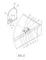
- FIGS. 2 and 3 are perspective views showing a process of assembling a bracket for retaining a mattress according to the preferred embodiment of the present invention
- FIG. 4 is a schematic lateral view showing a part of the bed and a mattress according to the preferred embodiment of the present invention.
- FIG. 5 is a sectional view taken along the line 5 - 5 in FIG. 4 ;
- FIG. 6 is a perspective view of a retainer of a bracket for retaining a mattress according to another preferred embodiment of the present invention.
- FIG. 7 is a perspective view of a retainer of a bracket for retaining a mattress according to still another preferred embodiment of the present invention.
- the bracket 10 is installed at an edge 7 of a bed frame 9 and capable of limiting the position of the mattress 6 placed on the bed frame 9 .
- the bracket 10 comprises a fastener 20 and a retainer 30 .
- the fastener 20 has two wings 21 both located on a same imaginary plane, and a convex 22 connecting the two wings 21 .
- the two wings 21 are mounted on a top surface 8 of the bed frame 9 .
- the two wings 21 may be fastened on the top surface 8 of the bed frame 9 by two screws 26 , or by other conventional fastening ways such as welding, gluing, wedging, and so on.
- the convex 22 is protruded from the imaginary plane and defines a passage 23 with the top surface 8 of the bed frame 9 .
- the convex 22 has a first end 24 , and a second end 25 closer to the edge 7 of the bed frame 9 than the first end 24 .
- the retainer 30 has an inserting portion 31 , two stop portions 33 , two extending portions 34 , two expanding portions 35 , and a retaining portion 36 .
- the inserting portion 31 is detachably inserted in the passage 23 .
- the inserting portion 31 is composed of two rods 32 abreast with each other.
- the two stop portions 33 extend in two adverse directions respectively from ends of the two rods 32 respectively, and abutted against the first end 24 of the convex 22 of the fastener 20 .
- the two extending portions 34 extend from the two stop portions 33 , respectively.
- the two extending portions 34 are abutted against two sides of the convex 22 of the fastener 20 respectively, and located on the two wings 21 , respectively.
- the two expanding portions 35 extend from the two extending portions 34 respectively in directions parallel to the edge 7 of the bed frame 9 , where the fastener 20 is installed.
- the retaining portion 36 is inverted U-shaped and has two ends connected with the two expanding portions 35 , respectively.
- the retaining portion 36 is adapted for being abutted against a side of the mattress 6 .
- the fastener 20 has been installed on the bed frame 9 before the user receives the bed frame 9 along with the bracket 10 .
- the user only needs to insert the inserting portion 31 of the retainer 30 in the passage 23 of the fastener 20 in the direction from the first end 24 to the second end 25 of the convex 22 until the stop portions 33 of the retainer 30 are abutted against the first end 24 of the convex 22 , such that the bracket 10 is completely assembled.
- the bracket 10 is positively convenient in assembly.
- each expanding portion 35 is provided for lowering the pressure between the retaining portion 36 and the mattress 6 .
- the bracket 10 may be provided without any such expanding portion 35 and still capable of being abutted against the side of the mattress 6 for retaining the mattress in position.
- each expanding portion 35 is not limited to be parallel to the edge 7 of the bed frame 9 , where the fastener 20 is installed.
- each expanding portion 35 may inclinedly extend relative to the edge 7 to a position distanced from the edge 7 . In such circumstance, only the extent that the retainer 30 matches the mattress is influenced, but the bracket 10 is still conveniently assembled.
- the extending portions 34 are abutted against the convex 22 of the fastener 20 enables the retainer 30 to be combined with the fastener 20 stably.
- the extending portions 34 may be not abutted against the convex 22 of the fastener 20 and the bracket, in this case, is still easily assembled.
- the inserting portion 31 may be not composed of two rods 32 , but shaped as other configurations capable of being inserted in the passage 23 , such as a long cube, and the retaining portion 36 may be not inverted U-shaped but shaped as other configurations such as a semicircle.
- the retainer 30 of the bracket 10 may be shaped as other configurations, such as a retainer 30 according to another preferred embodiment as shown in FIG. 6 .
- the retainer 30 has same inserting portion 31 , stop portions 33 , extending portions 34 and expanding portions 35 as mentioned in preceding embodiment, and two retaining portions 361 different from the aforesaid retaining portion 36 .
- the expending portions 35 are connected with ends of the retaining portions 361 , respectively.
- the two retaining portions 361 extend from the two expending portions 35 towards two sides of the bed frame, so the retainer can be abutted against a relatively larger area of the mattress, thereby being more effective in retaining the mattress.
- the expanding portions 35 may be omitted and the retainer 30 may have only one of the retaining portions 361 , which is connected with one of the extending portions 34 , and be still effective in retaining the mattress.
- the retainer 30 of the bracket 10 may be shaped as other configurations, such as a retainer 30 according to still another preferred embodiment as shown in FIG. 7 .
- the retainer 30 is shaped as a bended plate with an opening, and has an inserting portion 31 , two stop portions 33 , two extending portions 34 and a retaining portion 36 . This kind of retainer is more conveniently manufactured and costs lower.
- the present invention further provides a bed in the embodiment shown in FIG. 1 .
- the bed 40 is adapted for retaining a mattress 6 placed on the bed 40 .
- the bed 40 comprises a bed frame 9 and four brackets 10 for retaining the mattress.
- the bed frame 9 is an electric bed frame and has a head portion 91 and a foot portion 92 .
- the bed frame 9 is adapted for supporting the mattress 6 thereon, and the head portion 91 can be raised or the foot portion 92 can be lowered.
- the structure of each bracket 10 and the possible variations thereof are illustrated above. In this way, the bed 40 in this embodiment has the easily assembled brackets 10 for retaining the mattress.
- the bed 40 may comprise only a bed frame 9 and a bracket 10 and can still attain the aforesaid another objective of the present invention.
- the bracket 10 may be installed at the foot portion 92 for preventing the mattress 6 from sliding down when the head portion 91 swings up.
Landscapes
- Mattresses And Other Support Structures For Chairs And Beds (AREA)
Abstract
An easily assembled bracket, adapted for being installed at an edge of a bed frame for retaining a mattress on the bed frame includes a fastener and a retainer. The fastener has two wings booth located on an imaginary plane, and a convex protruded from the imaginary plane. A passage is provided between the convex and a top surface of the bed frame. The retainer has an inserting portion detachably inserted in the passage, two stop portions extending from the inserting portion in two adverse directions respectively and abutted against an end of the convex, two extending portions extending from the two stop portions respectively, and at least one retaining portion connected with at least one of the extending portions for being abutted against a side of the mattress.
Description
1. Field of the Invention
The present invention relates generally to a bracket for retaining a mattress and more particularly, to a conveniently assembled bracket for retaining a mattress, and a bed equipped with the same.
2. Description of the Related Art
A mattress placed on a bed frame might be displaced when receiving an external force. For example, when a user violently exercises or jumps on the mattress, the mattress is displaced little by little. For an electric powered bed frame having an adjustable head portion, the mattress might be displaced toward a foot portion of the bed frame when the head portion is raised. A conventional bracket, which is installed on the bed frame, has a part extending upwards from the bed frame and abutted against a side of the mattress for retaining the mattress. Because the bracket for retaining the mattress has the upwards extending part, a plurality of said bed frames provided with such brackets are difficult to be orderly stacked upon one another, which causes relatively higher cost in transportation and storage. The way of the dealers in the industry for solving the aforesaid problem is that the bracket is not installed on the bed frame beforehand. The bracket will be installed on the bed frame by a consumer after the consumer buys the bed frame along with the bracket. Under this circumstance, the consumer needs tools and skills for assembling the bracket, which causes inconvenience to the consumer.
In other words, the conventional bracket for retaining the mattress is not easily assembled by the user. Therefore, how to provide a conveniently assembled bracket for retaining a mattress is an anxious problem for the dealers in the industry.
The present invention has been accomplished in view of the above-noted circumstances. It is an objective of the present invention to provide a bracket for retaining a mattress, which is conveniently assembled.
To attain the above objective, the present invention provides a bracket which is adapted to be installed at an edge of a bed frame for retaining a mattress placed on the bed frame. The bracket comprises a fastener and a retainer. The fastener has two wings both located on an imaginary plane, and a convex connected between the two wings and protruded from the imaginary plane. The two wings are adapted to be mounted on a top surface of the bed frame in such a way that the convex defines a passage with the top surface of the bed frame. The convex has a first end and a second end closer to the edge of the bed frame than the first end. The retainer has an inserting portion detachably inserted in the passage, two stop portions extending from an end of the inserting portion in two adverse directions respectively and abutted against the first end of the convex of the fastener, two extending portions extending from the two stop portions respectively, located at two sides of the convex of the fastener respectively and located on the two wings respectively; and at least one retaining portion connected with at least one of the extending portions for being abutted against a side of the mattress.
It is another objective of the present invention to provide a bed which has a conveniently assembled bracket for retaining a mattress.
To attain the above objective, the present invention provides a bed adapted for retaining a mattress placed thereon. The bed comprises a bed frame on which the mattress is placed, and a bracket having a fastener and a retainer. The fastener has two wings both located on an imaginary plane, and a convex connected between the two wings. The two wings are mounted on a top surface of the bed frame. The convex is protruded from the imaginary plane. A passage is provided between the convex and the top surface of the bed frame. The convex has a first end and a second end closer to an edge of the bed frame than the first end. The retainer has an inserting portion, two stop portions, two extending portions, and at least one retaining portion. The inserting portion is detachably inserted in the passage. The two stop portions extend from an end of the inserting portion in two adverse directions respectively, and are abutted against the first end of the convex of the fastener. The two extending portions extend from the two stop portions respectively, and are respectively located at two sides of the convex of the fastener respectively and located on the two wings, respectively. The at least one retaining portion is connected with at least one of the extending portions for being abutted against a side of the mattress.
As a result, the fastener can be installed on the bed frame by the dealer before the bed frame and the bracket are transported to a user. After receiving the bed frame and the bracket, the user only needs to insert the retainer in the fastener, such that the bracket is completely assembled. In this way, the bracket is conveniently and easily assembled by the user without any additional tools and skills.
The present invention will become more fully understood from the detailed description given herein below and the accompanying drawings which are given by way of illustration only, and thus are not limitative of the present invention, and wherein:
First of all, a bracket for retaining a mattress according to a preferred embodiment of the present invention is illustrated. Referring to FIG. 1 , the bracket 10 is installed at an edge 7 of a bed frame 9 and capable of limiting the position of the mattress 6 placed on the bed frame 9. Referring to FIGS. 2-5 , the bracket 10 comprises a fastener 20 and a retainer 30.
The fastener 20 has two wings 21 both located on a same imaginary plane, and a convex 22 connecting the two wings 21. The two wings 21 are mounted on a top surface 8 of the bed frame 9. The two wings 21 may be fastened on the top surface 8 of the bed frame 9 by two screws 26, or by other conventional fastening ways such as welding, gluing, wedging, and so on. The convex 22 is protruded from the imaginary plane and defines a passage 23 with the top surface 8 of the bed frame 9. The convex 22 has a first end 24, and a second end 25 closer to the edge 7 of the bed frame 9 than the first end 24.
The retainer 30 has an inserting portion 31, two stop portions 33, two extending portions 34, two expanding portions 35, and a retaining portion 36. The inserting portion 31 is detachably inserted in the passage 23. The inserting portion 31 is composed of two rods 32 abreast with each other. The two stop portions 33 extend in two adverse directions respectively from ends of the two rods 32 respectively, and abutted against the first end 24 of the convex 22 of the fastener 20. The two extending portions 34 extend from the two stop portions 33, respectively. The two extending portions 34 are abutted against two sides of the convex 22 of the fastener 20 respectively, and located on the two wings 21, respectively. The two expanding portions 35 extend from the two extending portions 34 respectively in directions parallel to the edge 7 of the bed frame 9, where the fastener 20 is installed. The retaining portion 36 is inverted U-shaped and has two ends connected with the two expanding portions 35, respectively. The retaining portion 36 is adapted for being abutted against a side of the mattress 6.
The following contents are about the way to assemble the bracket 10 by the user. As shown in FIGS. 2 and 3 , the fastener 20 has been installed on the bed frame 9 before the user receives the bed frame 9 along with the bracket 10. The user only needs to insert the inserting portion 31 of the retainer 30 in the passage 23 of the fastener 20 in the direction from the first end 24 to the second end 25 of the convex 22 until the stop portions 33 of the retainer 30 are abutted against the first end 24 of the convex 22, such that the bracket 10 is completely assembled.
In this way, only one step of inserting the retainer to the fastener needs to be performed by the user to assemble the bracket, and the step can be performed without any additional tools and skills. For example, the user doesn't need to align two parts of the retainer and then insert the two parts into two fasteners simultaneously. Therefore, the bracket 10 is positively convenient in assembly.
It is to be mentioned that each expanding portion 35 is provided for lowering the pressure between the retaining portion 36 and the mattress 6. However, the bracket 10 may be provided without any such expanding portion 35 and still capable of being abutted against the side of the mattress 6 for retaining the mattress in position. Besides, each expanding portion 35 is not limited to be parallel to the edge 7 of the bed frame 9, where the fastener 20 is installed. For example, each expanding portion 35 may inclinedly extend relative to the edge 7 to a position distanced from the edge 7. In such circumstance, only the extent that the retainer 30 matches the mattress is influenced, but the bracket 10 is still conveniently assembled.
The feature that the extending portions 34 are abutted against the convex 22 of the fastener 20 enables the retainer 30 to be combined with the fastener 20 stably. However, the extending portions 34 may be not abutted against the convex 22 of the fastener 20 and the bracket, in this case, is still easily assembled. In addition, the inserting portion 31 may be not composed of two rods 32, but shaped as other configurations capable of being inserted in the passage 23, such as a long cube, and the retaining portion 36 may be not inverted U-shaped but shaped as other configurations such as a semicircle.
Based on the design concept of the present invention, the retainer 30 of the bracket 10 may be shaped as other configurations, such as a retainer 30 according to another preferred embodiment as shown in FIG. 6 . The retainer 30 has same inserting portion 31, stop portions 33, extending portions 34 and expanding portions 35 as mentioned in preceding embodiment, and two retaining portions 361 different from the aforesaid retaining portion 36. The expending portions 35 are connected with ends of the retaining portions 361, respectively. The two retaining portions 361 extend from the two expending portions 35 towards two sides of the bed frame, so the retainer can be abutted against a relatively larger area of the mattress, thereby being more effective in retaining the mattress. It is to be mentioned that the expanding portions 35 may be omitted and the retainer 30 may have only one of the retaining portions 361, which is connected with one of the extending portions 34, and be still effective in retaining the mattress.
The retainer 30 of the bracket 10 may be shaped as other configurations, such as a retainer 30 according to still another preferred embodiment as shown in FIG. 7 . The retainer 30 is shaped as a bended plate with an opening, and has an inserting portion 31, two stop portions 33, two extending portions 34 and a retaining portion 36. This kind of retainer is more conveniently manufactured and costs lower.
The present invention further provides a bed in the embodiment shown in FIG. 1 . The bed 40 is adapted for retaining a mattress 6 placed on the bed 40. The bed 40 comprises a bed frame 9 and four brackets 10 for retaining the mattress. The bed frame 9 is an electric bed frame and has a head portion 91 and a foot portion 92. The bed frame 9 is adapted for supporting the mattress 6 thereon, and the head portion 91 can be raised or the foot portion 92 can be lowered. The structure of each bracket 10 and the possible variations thereof are illustrated above. In this way, the bed 40 in this embodiment has the easily assembled brackets 10 for retaining the mattress.
It is to be mentioned that the bed 40 may comprise only a bed frame 9 and a bracket 10 and can still attain the aforesaid another objective of the present invention. For example, the bracket 10 may be installed at the foot portion 92 for preventing the mattress 6 from sliding down when the head portion 91 swings up.
The invention being thus described, it will be obvious that the same may be varied in many ways. Such variations are not to be regarded as a departure from the spirit and scope of the invention, and all such modifications as would be obvious to one skilled in the art are intended to be included within the scope of the following claims.
Claims (10)
1. A bracket for being installed at an edge of a bed frame for retaining a mattress placed on the bed frame, the bracket consisting of:
a fastener having two wings both located on an imaginary plane, and a convex connected between the two wings and protruded from said imaginary plane; the two wings being adapted for being mounted on a top surface of the bed frame in a way that the convex defines a passage with the top surface of the bed frame; the convex having a first end and a second end closer to the edge of the bed frame than the first end; and
a retainer having an inserting portion detachably inserted in the passage, two stop portions extending from an end of the inserting portion in two adverse directions respectively and abutted against the first end of the convex of the fastener, two extending portions extending from the two stop portions respectively, located at two sides of the convex of the fastener respectively and located on the two wings respectively, at least one retaining portion connected with at least one of the extending portions for being abutted against a side of the mattress, and two expanding portions each connected between one said extending portion and one said retaining portion, the expanding portions extending in a horizontal direction parallel to the edge between the top surface and a side surface of the bed frame where the fastener is installed.
2. The bracket as claimed in claim 1 , wherein the retainer has one said retaining portion having two ends connected with the two extending portions, respectively.
3. The bracket as claimed in claim 1 , wherein the retainer has two said retaining portions connected with the two extending portions, respectively.
4. The bracket as claimed in claim 1 , wherein the inserting portion is composed of two rods abreast with each other; the two stop portions extend in the two adverse directions from ends of the two rods, respectively.
5. The bracket as claimed in claim 1 , wherein the extending portions of the retainer are abutted against the convex of the fastener.
6. A bed for retaining a mattress placed thereon, the bed comprising:
a bed frame for supporting the mattress thereon; and
a bracket consisting of a fastener and a retainer, wherein the fastener has two wings both located on an imaginary plane, and a convex connected between the two wings; the two wings are mounted on a top surface of the bed frame; the convex is protruded from said imaginary plane in a way that a passage is provided between the convex and the top surface of the bed frame; the convex has a first end and a second end closer to an edge of the bed frame than the first end; the retainer has an inserting portion, two stop portions, two extending portions, at least one retaining portion and two expanding portions; the inserting portion is detachably inserted in the passage; the two stop portions extend from an end of the inserting portion in two adverse directions respectively, and are abutted against the first end of the convex of the fastener; the two extending portions extend from the two stop portions respectively, and are located at two sides of the convex of the fastener respectively and located on the two wings respectively; the at least one retaining portion is connected with at least one of the extending portions for being abutted against a side of the mattress; the expanding portions each are connected between one said extending portion and one said retaining portion; the expanding portions extend in a horizontal direction parallel to the edge between the top surface and a side surface of the bed frame where the fastener is installed.
7. The bed as claimed in claim 6 , wherein the retainer has one said retaining portion having two ends connected with the two extending portions, respectively.
8. The bed as claimed in claim 6 , wherein the retainer has two said retaining portions connected with the two extending portions, respectively.
9. The bed as claimed in claim 6 , wherein the inserting portion is composed of two rods abreast with each other; the two stop portions extend in the two adverse directions from ends of the two rods, respectively.
10. The bed as claimed in claim 6 , wherein the extending portions of the retainer are abutted against the convex of the fastener.
Priority Applications (1)
Application Number | Priority Date | Filing Date | Title |
---|---|---|---|
US14/737,144 US9986844B2 (en) | 2015-06-11 | 2015-06-11 | Bracket for retaining mattress and bed equipped with the same |
Applications Claiming Priority (1)
Application Number | Priority Date | Filing Date | Title |
---|---|---|---|
US14/737,144 US9986844B2 (en) | 2015-06-11 | 2015-06-11 | Bracket for retaining mattress and bed equipped with the same |
Publications (2)
Publication Number | Publication Date |
---|---|
US20160360894A1 US20160360894A1 (en) | 2016-12-15 |
US9986844B2 true US9986844B2 (en) | 2018-06-05 |
Family
ID=57516161
Family Applications (1)
Application Number | Title | Priority Date | Filing Date |
---|---|---|---|
US14/737,144 Active 2035-12-15 US9986844B2 (en) | 2015-06-11 | 2015-06-11 | Bracket for retaining mattress and bed equipped with the same |
Country Status (1)
Country | Link |
---|---|
US (1) | US9986844B2 (en) |
Cited By (4)
Publication number | Priority date | Publication date | Assignee | Title |
---|---|---|---|---|
USD909805S1 (en) * | 2018-02-15 | 2021-02-09 | Michael F. Kunde | Transfer bar |
US11344132B2 (en) * | 2019-03-18 | 2022-05-31 | Leggett & Platt, Inc. | Adjustable bed with load distribution bracket |
US11576498B1 (en) * | 2016-03-14 | 2023-02-14 | Thomas Stern | Apparatus for preventing slippage of stacked objects |
US11684530B2 (en) | 2019-04-12 | 2023-06-27 | Hill-Rom Services, Inc. | Mattress retention assembly and radiofrequency weld in surface covers |
Families Citing this family (1)
Publication number | Priority date | Publication date | Assignee | Title |
---|---|---|---|---|
US20200046133A1 (en) * | 2018-08-09 | 2020-02-13 | Apex Health Care Mfg. Inc | Stop Structure for Mattress of Electric Bed |
Citations (23)
Publication number | Priority date | Publication date | Assignee | Title |
---|---|---|---|---|
US1031656A (en) * | 1912-04-05 | 1912-07-02 | Link Fabric Company Of America | Mattress-guard. |
US1371098A (en) * | 1920-09-25 | 1921-03-08 | Mariana T Jones | Mattress-holder |
US3474473A (en) * | 1967-11-09 | 1969-10-28 | Orrin Hannaberg | Adjustable hand rail attachment for a bed and mattress |
US4017919A (en) * | 1976-02-12 | 1977-04-19 | Hemmeter John H | Mattress guard |
US4297754A (en) * | 1979-12-10 | 1981-11-03 | Zuniga Julio A | Box spring and mattress support device |
US4554692A (en) * | 1984-12-13 | 1985-11-26 | Leggett & Platt, Incorporated | Adjustable box spring retainer bracket |
US5195200A (en) * | 1992-04-17 | 1993-03-23 | Thomas Leoutsakos | Manual support apparatus attachable to a bedframe |
US5400450A (en) * | 1992-04-17 | 1995-03-28 | Leoutsakos; Thomas | Manual support apparatus |
US5448791A (en) * | 1993-05-10 | 1995-09-12 | Brown; David J. | Support mechanism for a bed |
US5471689A (en) * | 1994-10-04 | 1995-12-05 | Shaw; Juliann P. | Bed handle system |
USD379283S (en) * | 1995-02-13 | 1997-05-20 | Santino Antinori | Mattress retention bracket for adjustable beds |
US5737783A (en) * | 1995-02-13 | 1998-04-14 | Antinori; Santino | Mattress retention bracket for adjustable beds |
US6374440B1 (en) * | 1999-04-20 | 2002-04-23 | Arthur W. Thim, Jr. | Back support |
US6401280B1 (en) * | 2000-12-26 | 2002-06-11 | Amy C. Baker | Portable bed railing |
US6834403B1 (en) * | 2003-06-26 | 2004-12-28 | Herron W. Elliott | Blanket elevation apparatus |
US7137158B2 (en) * | 2002-08-30 | 2006-11-21 | Mark A. Flannery | Mattress hugging bed rail |
US7607181B1 (en) * | 2009-01-26 | 2009-10-27 | L & P | Mattress retainer blocks |
US8646130B2 (en) * | 2010-07-26 | 2014-02-11 | Tempur-Pedic Management, Llc | Mattress retention bracket assembly and method |
US8769739B1 (en) * | 2013-08-22 | 2014-07-08 | Philip Woods McCarty | Bracket for retaining a bed mattress |
US8776294B1 (en) * | 2013-07-17 | 2014-07-15 | Philip Woods McCarty | Bracket for retaining mattress |
US8800079B1 (en) * | 2013-09-26 | 2014-08-12 | Doreen Eubank | Bed cover holder |
US9044365B2 (en) * | 2006-09-14 | 2015-06-02 | Ascion, Llc | Mattress support facility with retaining brackets |
US9474386B2 (en) * | 2014-06-13 | 2016-10-25 | Levitation Sciences Llc | Adjustable mattress retainer bars |
-
2015
- 2015-06-11 US US14/737,144 patent/US9986844B2/en active Active
Patent Citations (23)
Publication number | Priority date | Publication date | Assignee | Title |
---|---|---|---|---|
US1031656A (en) * | 1912-04-05 | 1912-07-02 | Link Fabric Company Of America | Mattress-guard. |
US1371098A (en) * | 1920-09-25 | 1921-03-08 | Mariana T Jones | Mattress-holder |
US3474473A (en) * | 1967-11-09 | 1969-10-28 | Orrin Hannaberg | Adjustable hand rail attachment for a bed and mattress |
US4017919A (en) * | 1976-02-12 | 1977-04-19 | Hemmeter John H | Mattress guard |
US4297754A (en) * | 1979-12-10 | 1981-11-03 | Zuniga Julio A | Box spring and mattress support device |
US4554692A (en) * | 1984-12-13 | 1985-11-26 | Leggett & Platt, Incorporated | Adjustable box spring retainer bracket |
US5195200A (en) * | 1992-04-17 | 1993-03-23 | Thomas Leoutsakos | Manual support apparatus attachable to a bedframe |
US5400450A (en) * | 1992-04-17 | 1995-03-28 | Leoutsakos; Thomas | Manual support apparatus |
US5448791A (en) * | 1993-05-10 | 1995-09-12 | Brown; David J. | Support mechanism for a bed |
US5471689A (en) * | 1994-10-04 | 1995-12-05 | Shaw; Juliann P. | Bed handle system |
USD379283S (en) * | 1995-02-13 | 1997-05-20 | Santino Antinori | Mattress retention bracket for adjustable beds |
US5737783A (en) * | 1995-02-13 | 1998-04-14 | Antinori; Santino | Mattress retention bracket for adjustable beds |
US6374440B1 (en) * | 1999-04-20 | 2002-04-23 | Arthur W. Thim, Jr. | Back support |
US6401280B1 (en) * | 2000-12-26 | 2002-06-11 | Amy C. Baker | Portable bed railing |
US7137158B2 (en) * | 2002-08-30 | 2006-11-21 | Mark A. Flannery | Mattress hugging bed rail |
US6834403B1 (en) * | 2003-06-26 | 2004-12-28 | Herron W. Elliott | Blanket elevation apparatus |
US9044365B2 (en) * | 2006-09-14 | 2015-06-02 | Ascion, Llc | Mattress support facility with retaining brackets |
US7607181B1 (en) * | 2009-01-26 | 2009-10-27 | L & P | Mattress retainer blocks |
US8646130B2 (en) * | 2010-07-26 | 2014-02-11 | Tempur-Pedic Management, Llc | Mattress retention bracket assembly and method |
US8776294B1 (en) * | 2013-07-17 | 2014-07-15 | Philip Woods McCarty | Bracket for retaining mattress |
US8769739B1 (en) * | 2013-08-22 | 2014-07-08 | Philip Woods McCarty | Bracket for retaining a bed mattress |
US8800079B1 (en) * | 2013-09-26 | 2014-08-12 | Doreen Eubank | Bed cover holder |
US9474386B2 (en) * | 2014-06-13 | 2016-10-25 | Levitation Sciences Llc | Adjustable mattress retainer bars |
Cited By (4)
Publication number | Priority date | Publication date | Assignee | Title |
---|---|---|---|---|
US11576498B1 (en) * | 2016-03-14 | 2023-02-14 | Thomas Stern | Apparatus for preventing slippage of stacked objects |
USD909805S1 (en) * | 2018-02-15 | 2021-02-09 | Michael F. Kunde | Transfer bar |
US11344132B2 (en) * | 2019-03-18 | 2022-05-31 | Leggett & Platt, Inc. | Adjustable bed with load distribution bracket |
US11684530B2 (en) | 2019-04-12 | 2023-06-27 | Hill-Rom Services, Inc. | Mattress retention assembly and radiofrequency weld in surface covers |
Also Published As
Publication number | Publication date |
---|---|
US20160360894A1 (en) | 2016-12-15 |
Similar Documents
Publication | Publication Date | Title |
---|---|---|
US9986844B2 (en) | Bracket for retaining mattress and bed equipped with the same | |
US9381414B1 (en) | Apparatus, system and methods for improved bag toss | |
US10321762B2 (en) | Wall anchoring assembly | |
US20170349080A1 (en) | Vehicle rooftop rack assembly | |
US9226588B2 (en) | Knockdown bed | |
CN107685813B (en) | Kettle rack and combined structure of kettle rack adapter | |
US9045197B2 (en) | Boat seat base assembly | |
US20080066266A1 (en) | Fastener assembly | |
US20170058534A1 (en) | Panel with a fastening device | |
US9995328B2 (en) | Bracket combination for attaching a leg to an item of furniture | |
US20170208946A1 (en) | Shelf Supporting Beam Configuration for Shelving Apparatus | |
US9241566B1 (en) | Modular shelving | |
ES2875749T3 (en) | Adapter element and transport platform including adapter elements | |
AU2020203897B2 (en) | Step clip fastening system and method | |
US8348210B1 (en) | Positioning device for shelves | |
US8356850B1 (en) | System and method for carrying and installing a plurality of empty ice bags into an ice bagging assembly | |
US8770553B2 (en) | Fence rail and picket assembly | |
US10017122B2 (en) | Vehicle storage compartment with reinforced mounting structure | |
US7640707B2 (en) | Fastening clip | |
US20070090243A1 (en) | Shelf shipping clip | |
US20130105645A1 (en) | Foldable support assembly | |
US11019940B2 (en) | Baby changing station | |
KR200465430Y1 (en) | Foldabel handle for box | |
US20150123530A1 (en) | Storage unit | |
US20230216282A1 (en) | Snap plug for cable tray |
Legal Events
Date | Code | Title | Description |
---|---|---|---|
STCF | Information on status: patent grant |
Free format text: PATENTED CASE |
|
MAFP | Maintenance fee payment |
Free format text: PAYMENT OF MAINTENANCE FEE, 4TH YR, SMALL ENTITY (ORIGINAL EVENT CODE: M2551); ENTITY STATUS OF PATENT OWNER: SMALL ENTITY Year of fee payment: 4 |