US9986371B2 - NFC power management device and method - Google Patents
NFC power management device and method Download PDFInfo
- Publication number
- US9986371B2 US9986371B2 US15/448,939 US201715448939A US9986371B2 US 9986371 B2 US9986371 B2 US 9986371B2 US 201715448939 A US201715448939 A US 201715448939A US 9986371 B2 US9986371 B2 US 9986371B2
- Authority
- US
- United States
- Prior art keywords
- nfc device
- power management
- nfc
- transceiver
- communication channel
- Prior art date
- Legal status (The legal status is an assumption and is not a legal conclusion. Google has not performed a legal analysis and makes no representation as to the accuracy of the status listed.)
- Active
Links
- 238000000034 method Methods 0.000 title claims abstract description 26
- 238000004891 communication Methods 0.000 claims abstract description 83
- 238000001514 detection method Methods 0.000 claims abstract description 26
- 230000004044 response Effects 0.000 claims abstract description 16
- 238000004590 computer program Methods 0.000 claims abstract description 7
- 238000012545 processing Methods 0.000 claims description 14
- 230000008859 change Effects 0.000 claims description 11
- 230000000737 periodic effect Effects 0.000 claims description 6
- 238000012544 monitoring process Methods 0.000 claims description 5
- 238000007726 management method Methods 0.000 description 80
- 230000008569 process Effects 0.000 description 6
- 238000005516 engineering process Methods 0.000 description 4
- 238000013461 design Methods 0.000 description 3
- 230000006870 function Effects 0.000 description 3
- 230000005540 biological transmission Effects 0.000 description 2
- 238000011161 development Methods 0.000 description 2
- 238000004519 manufacturing process Methods 0.000 description 2
- 230000008901 benefit Effects 0.000 description 1
- 230000001413 cellular effect Effects 0.000 description 1
- 230000001934 delay Effects 0.000 description 1
- 230000001419 dependent effect Effects 0.000 description 1
- 230000003993 interaction Effects 0.000 description 1
- 230000003287 optical effect Effects 0.000 description 1
- 239000013307 optical fiber Substances 0.000 description 1
- 239000004065 semiconductor Substances 0.000 description 1
- 230000003068 static effect Effects 0.000 description 1
Images


Classifications
-
- H—ELECTRICITY
- H04—ELECTRIC COMMUNICATION TECHNIQUE
- H04B—TRANSMISSION
- H04B5/00—Near-field transmission systems, e.g. inductive or capacitive transmission systems
- H04B5/70—Near-field transmission systems, e.g. inductive or capacitive transmission systems specially adapted for specific purposes
- H04B5/72—Near-field transmission systems, e.g. inductive or capacitive transmission systems specially adapted for specific purposes for local intradevice communication
-
- H04W4/008—
-
- H—ELECTRICITY
- H04—ELECTRIC COMMUNICATION TECHNIQUE
- H04W—WIRELESS COMMUNICATION NETWORKS
- H04W4/00—Services specially adapted for wireless communication networks; Facilities therefor
- H04W4/80—Services using short range communication, e.g. near-field communication [NFC], radio-frequency identification [RFID] or low energy communication
-
- H—ELECTRICITY
- H04—ELECTRIC COMMUNICATION TECHNIQUE
- H04W—WIRELESS COMMUNICATION NETWORKS
- H04W52/00—Power management, e.g. TPC [Transmission Power Control], power saving or power classes
- H04W52/02—Power saving arrangements
- H04W52/0209—Power saving arrangements in terminal devices
- H04W52/0225—Power saving arrangements in terminal devices using monitoring of external events, e.g. the presence of a signal
- H04W52/0229—Power saving arrangements in terminal devices using monitoring of external events, e.g. the presence of a signal where the received signal is a wanted signal
- H04W52/0232—Power saving arrangements in terminal devices using monitoring of external events, e.g. the presence of a signal where the received signal is a wanted signal according to average transmission signal activity
-
- H—ELECTRICITY
- H04—ELECTRIC COMMUNICATION TECHNIQUE
- H04W—WIRELESS COMMUNICATION NETWORKS
- H04W52/00—Power management, e.g. TPC [Transmission Power Control], power saving or power classes
- H04W52/02—Power saving arrangements
- H04W52/0209—Power saving arrangements in terminal devices
- H04W52/0225—Power saving arrangements in terminal devices using monitoring of external events, e.g. the presence of a signal
- H04W52/0235—Power saving arrangements in terminal devices using monitoring of external events, e.g. the presence of a signal where the received signal is a power saving command
-
- H04W76/02—
-
- H04W76/06—
-
- H—ELECTRICITY
- H04—ELECTRIC COMMUNICATION TECHNIQUE
- H04W—WIRELESS COMMUNICATION NETWORKS
- H04W76/00—Connection management
- H04W76/10—Connection setup
-
- H—ELECTRICITY
- H04—ELECTRIC COMMUNICATION TECHNIQUE
- H04W—WIRELESS COMMUNICATION NETWORKS
- H04W76/00—Connection management
- H04W76/30—Connection release
-
- Y—GENERAL TAGGING OF NEW TECHNOLOGICAL DEVELOPMENTS; GENERAL TAGGING OF CROSS-SECTIONAL TECHNOLOGIES SPANNING OVER SEVERAL SECTIONS OF THE IPC; TECHNICAL SUBJECTS COVERED BY FORMER USPC CROSS-REFERENCE ART COLLECTIONS [XRACs] AND DIGESTS
- Y02—TECHNOLOGIES OR APPLICATIONS FOR MITIGATION OR ADAPTATION AGAINST CLIMATE CHANGE
- Y02D—CLIMATE CHANGE MITIGATION TECHNOLOGIES IN INFORMATION AND COMMUNICATION TECHNOLOGIES [ICT], I.E. INFORMATION AND COMMUNICATION TECHNOLOGIES AIMING AT THE REDUCTION OF THEIR OWN ENERGY USE
- Y02D30/00—Reducing energy consumption in communication networks
- Y02D30/70—Reducing energy consumption in communication networks in wireless communication networks
Definitions
- the present disclosure relates to an NFC device. Furthermore, the present disclosure relates to a method for managing power in an NFC device and to a corresponding computer program product.
- NFC Near field communication
- NFC technology enables simple and safe two-way interactions between electronic devices, allowing consumers to perform contactless transactions, access digital content, and connect electronic devices with a single touch.
- NFC complements many popular consumer-level wireless technologies by utilizing the key elements in existing standards for contactless smart card technology.
- NFC is compatible with existing contactless smart card infrastructures and thus it enables a consumer to utilize one device across different systems.
- There are various types of NFC devices for example simple NFC tags, stickers or cards, NFC-enabled mobile devices such as smart phones, and NFC readers integrated in point-of-sale (POS) terminals.
- An NFC tag or NFC card is usually a passive device, i.e.
- HCE Host Card Emulation
- HCE Host Card Emulation
- an NFC device which comprises: a transceiver unit configured to establish a communication channel between the NFC device and a further NFC device, said further NFC device being external to the NFC device; a power management unit configured to detect an inactive communication state of said communication channel and to cause the transceiver unit to enter into a power management mode in response to a detection of said inactive communication state.
- the power management unit is further configured to detect said inactive communication state by monitoring application-level communication between the NFC device and the further NFC device.
- the application-level communication comprises transmit and receive operations performed by the transceiver unit.
- said transmit and receive operations comprise transmitting commands, receiving responses and time-out operations.
- the power management unit is further configured, upon or after detection of said inactive communication state, to cause the transceiver unit to disconnect the communication channel.
- the power management unit is further configured, upon or after detection of said inactive communication state, to cause the transceiver unit and to enter into a periodic polling mode.
- the power management unit is further configured to cause the transceiver unit to reduce the polling frequency in said periodic polling mode.
- the power management unit is further configured to cause the transceiver unit to poll only for devices having a type which is different from the type of said further NFC device.
- the power management unit is further configured to store an identifier of said further NFC device.
- the power management unit is further configured to prevent the transceiver unit from establishing a new communication channel, upon or after verifying that a newly received identifier matches the stored identifier.
- the power management unit is further configured to detect one or more conditions for exiting the power management mode, and the power management unit is further configured to cause the transceiver unit to exit the power management mode upon or after detection of said conditions.
- the one or more conditions include a change in the RF load on the transceiver unit.
- the NFC device is an NFC-enabled mobile device acting as an NFC reader, an NFC reader integrated in a terminal or an NFC peer device.
- a method for managing power in an NFC device comprising: establishing, by a transceiver unit of said NFC device, a communication channel between the NFC device and a further NFC device, said further NFC device being external to the NFC device; detecting, by a power management unit of said NFC device, an inactive communication state of said communication channel; causing, by said power management unit, the transceiver unit to enter into a power management mode in response to a detection of said inactive communication state.
- a tangible, non-transitory computer program product comprises instructions for execution by a processing unit which, when executed by the processing unit, cause said processing unit to carry out or control a method of the kind set forth.
- FIG. 1 shows an illustrative embodiment of an NFC system
- FIG. 2 shows an illustrative embodiment of a power management method
- FIG. 3 shows an illustrative embodiment of an implementation of a power management method of the kind set forth
- FIG. 4 shows an illustrative embodiment of a further implementation of a power management method of the kind set forth
- FIG. 5 shows an illustrative embodiment of a further implementation of a power management method of the kind set forth
- FIG. 6 shows an illustrative embodiment of a further implementation of a power management method of the kind set forth.
- NFC tag or card may be placed in a flip cover of an NFC-enabled mobile phone.
- the NFC modem or transceiver of the phone will be switched on and it will detect the NFC tag/card placed in the flip cover. Subsequently, it will establish a communication channel with the NFC tag/card.
- the NFC modem is in full power mode and it draws power from the phone's battery, while, when the user is using another mobile function (e.g., phone call, internet browsing) there is no requirement of communication with the detected NFC tag/card.
- another mobile function e.g., phone call, internet browsing
- two NFC devices may have been left in proximity of each other, in which case they may connect to each other while there is no requirement for communication. If the NFC devices are connected in peer-to-peer mode, the NFC transceivers in both devices may drain power from the devices' batteries.
- an NFC-enabled mobile device may be placed inadvertently on an NFC card (e.g., an NFC-enabled credit card or office access tag).
- the NFC transceiver of the mobile device may unnecessarily drain power from the device's battery.
- the mobile device may have a power management function, it may wait with switching off the NFC transceiver until the device enters into sleep mode, for example. Since this may take a significant amount of time, power may be consumed for quite some time.
- a user may again flip the cover of a mobile phone, and an NFC tag or card in the cover may be detected, which triggers the NFC transceiver in the phone to establish a communication channel.
- This communication channel will normally not be disconnected before the NFC card/tag is removed from the RF field generated by said transceiver.
- the new NFC device tag/card/peer
- the new NFC device which is brought into proximity of the phone will only be detected in a new RF poll cycle, which will only take place when the flip-cover tag/card is no longer close to the transceiver.
- This may result in functionality loss. For instance, the user may have to keep the cover half open, so that the flip-cover tag/card is not in proximity and then bring the new NFC device into proximity, which is inconvenient.
- an NFC device which comprises: a transceiver unit configured to establish a communication channel between the NFC device and a further NFC device, said further NFC device being external to the NFC device; a power management unit configured to detect an inactive communication state of said communication channel and to cause the transceiver unit to enter into a power management mode upon or after detection of said inactive communication state.
- FIG. 1 shows an illustrative embodiment of an NFC system 100 .
- the system 100 comprises an NFC device 102 of the kind set forth and a further, external NFC device 108 .
- the NFC device 102 may be an NFC-enabled mobile device acting as an NFC reader, such as a smart phone or a tablet, or an NFC reader integrated in a point-of-sale (POS) terminal, for example.
- the external NFC device 108 may be an NFC tag, an NFC card or an NFC-enabled mobile device operating in peer-to-peer mode.
- the NFC device 102 may be a mobile phone containing a flip cover in which the further NFC device 108 (e.g., an NFC-enabled smart card) is stored.
- the NFC device 102 comprises a power management unit 104 which is operatively connected to an NFC transceiver 106 .
- the NFC transceiver 106 may establish a communication channel with the external NFC device 108 by generating an RF field and execute a polling procedure; subsequently, when the presence of the external NFC device 108 is detected, the NFC channel may be established.
- the external NFC device 108 has been brought intentionally into proximity of the NFC device 102 , data will be communicated through the NFC channel.
- the power management unit 104 is configured to detect that the NFC channel has an inactive communication state. If this is the case, the power management unit 104 may trigger the NFC transceiver 106 to enter into a power management mode in which appropriate power saving measures may be taken.
- the NFC transceiver 106 may be a commonly available integrated circuit component.
- the power management unit 104 may be a software-implemented block designed to control functions of the NFC transceiver 106 .
- the power management unit 104 may for example be embedded in a microcontroller or processing unit (not shown) that controls the NFC transceiver 106 , or form a separate module.
- the power management unit 104 is at least partly embedded in the NFC transceiver 106 .
- FIG. 2 shows an illustrative embodiment of a power management method 200 .
- the method comprises, at 202 , establishing, by the transceiver unit 106 , a communication channel between the NFC device 102 and the external NFC device 108 . Furthermore, the method comprises, at 204 , detecting, by the power management unit 104 , an inactive communication state of the communication channel, and at 206 , triggering the transceiver unit 106 to enter into a power management mode upon or after detection of the inactive communication state.
- the power management unit 104 may detect the inactive communication state by monitoring application-level communication between the NFC device 102 and the external NFC device 108 . Thereby, detecting the inactive communication state may be facilitated. For instance, the power management unit 104 may trigger the transceiver unit 106 to enter into the power management mode if no application-level communication has taken place for a predefined amount of time. This amount of time may also be configurable, so as to achieve a balance between fast entry into the power management mode and the avoidance of use case interference.
- the NFC device 102 may comprise an application processor (not shown) or another processing unit that exchanges data with the external NFC device 108 through the NFC transceiver 106 .
- the NFC transceiver 106 may enable the data exchange by performing transmit operations and receive operations.
- the power management unit 104 may detect the inactive communication state by monitoring these transmit operations and receive operations. Thereby, said detection may be further facilitated.
- operations which are easy to monitor include, but are not limited to, the transmission of commands by the NFC transceiver 106 , the receipt of responses by the NFC transceiver 106 , and time-out operations performed by the NFC transceiver 106 .
- the time-out operation may include verifying whether a response to a specific command has been received from the external NFC device 108 , and generating a time-out when the response has not been received.
- a command may be transmitted and a response received, subsequently no other command may be transmitted for a predefined amount of time, and thus it is concluded that the communication is inactive.
- a command may be transmitted, but no response may be received for a predefined amount of time, as a result a time-out may be generated, subsequently no other command may be transmitted for a predefined amount of time, and thus it is concluded that the communication is inactive.
- the power management unit 104 is further configured, upon or after detection of the inactive communication state, to cause the NFC transceiver 106 to disconnect the communication channel and to enter into a periodic polling mode.
- the power consumption may be reduced significantly because no battery power needs to be used to maintain the communication channel.
- the power management unit 104 is further configured to trigger the NFC transceiver 106 to reduce the polling frequency. Although periodic polling requires less energy than maintaining the communication channel, battery power is still used. Thus, reducing the polling frequency may further reduce the power consumption. The inventors have realized that it is probable that only the external NFC device 108 that is already in proximity will be detected during said polling, and that consequently there is no need for a high polling frequency.
- the power management unit 104 is also configured to trigger the NFC transceiver 106 to poll only for devices having a type which is different from the type of the external NFC device 108 . In this way, it can be prevented that a new and probably unused communication channel is set up with the external NFC device 108 , while it allows detecting an external NFC device of another type when it enters the RF field of the NFC device 102 .
- NFC devices such as those defined by the NFC Forum, and proprietary types of NFC devices.
- the NFC transceiver 106 may poll for all devices not being of Type 2, i.e. only for NFC Forum Type 1/3/4 Tags and proprietary types of NFC devices. If a device of such another type has been detected, the NFC transceiver 106 may exit the power management mode and establish a communication channel with the new device.
- the power management unit 104 is further configured to store an identifier of the external NFC device 108 , for example upon or after detection of the inactive communication state. This may enable ignoring the external NFC device 108 if it is again detected by the polling process performed in the power management mode. In particular, it may not be desirable to ignore all NFC devices of a particular type, because it may be the user's intention to communicate with another external NFC device of the same type.
- an identifier of the external NFC device 108 when entering the power management mode (e.g., a unique number stored on said NFC device 108 and provided to the NFC transceiver 106 ) it can be verified whether the same device is again detected, and if so, it may be ignored.
- the power management unit 104 may prevent the NFC transceiver 106 from establishing a new communication channel upon or after verifying that a newly received identifier matches the stored identifier.
- the power management unit is further configured to detect one or more conditions for exiting the power management mode, and the power management unit is further configured to cause the transceiver unit to exit the power management mode upon or after detection of said conditions.
- An example of such an exit condition is a change in the RF load on the NFC transceiver 106 .
- the power management unit 104 may be configured to detect a change in the RF load on the NFC transceiver 106 and to cause the NFC transceiver 106 to exit the power management mode upon or after detection of said change.
- the change of the RF load provides a good indication of the presence of a new external NFC device in the field generated by the NFC transceiver 106 , which in turn may be indicative of a user's intention to start communication with another NFC device.
- An external NFC device appears as a certain load on the RF field generated by the NFC transceiver 106 .
- the NFC transceiver 106 may monitor the load on its RF field and thus detect such change of the RF load, in order to determine that a new NFC device enters the field.
- the NFC transceiver 106 may exit the power management mode and establish a communication channel with the new NFC device.
- the change detection process may use a configurable threshold, in that the NFC transceiver 106 may conclude that a new NFC device has entered the field only if the change of the RF load exceeds said threshold.
- a hysteresis value may be taken into account. Both the threshold and the hysteresis value may facilitate the avoidance of false detections.
- FIG. 3 shows an illustrative embodiment of an implementation of a power management method of the kind set forth. In particular, it shows a high-level sequence of events in a power saving method of the kind set forth.
- an inactive communication state detection process is started at 306 .
- the inactive communication state is called a perpetual NFC ON situation, which refers to the fact that the communication channel remains established while no actual communication takes place.
- the NFC transceiver enters the power management mode at 310 .
- an exit condition detection process for detecting one or more conditions for exiting said power management mode may be started at 312 ; an example of such a condition (i.e., criterion) may be the above-mentioned change of the RF load.
- criterion i.e., the NFC transceiver may return to a normal operating mode.
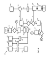
- FIG. 4 shows an illustrative embodiment of a further implementation of a power management method of the kind set forth.
- FIG. 4 shows a lower-level sequence of events in a power saving method of the kind set forth.
- blocks 408 , 410 , 412 , 414 , 416 , 418 and 446 represent events associated with the detection of the inactive communication state.
- block 420 represents an event associated with entering into the power management mode.
- blocks 426 , 428 , 430 and 436 represent blocks associated with exiting the power management mode and returning to the normal operating mode. The remaining blocks represent events associated with the normal operating mode of the NFC transceiver.
- the sequence of events 432 , 434 , 436 may run in parallel to other sequences, such as the sequence of events 438 , 440 and the sequence of events 442 , 444 .
- the sequence of events 432 , 434 , 436 indicates that operating the NFC transceiver in power management mode is no longer required if the NFC device's screen is locked or switched off, because in that case the NFC channel will be disconnected anyhow.
- the sequence of events 442 , 444 indicates that the occurrence of transmit and receive operations (“transceiver operations”) re-starts the timer, which effectively delays entering the power management mode.
- the absence of transmit and receive operations during a predefined amount of time may trigger the NFC transceiver to enter into the power management mode.
- applications executed by the NFC device's processing unit may attempt to connect or reconnect 440 to the NFC transceiver, in order to initiate a data exchange with an external NFC device.
- This event 440 may also be used as a trigger to re-start the timer, thus effectively delaying entering the power management mode.
- entry point A and exit points B and C show how the sequence of events relates to the sequences of events shown in FIG. 5 and FIG. 6 .
- FIG. 5 shows an illustrative embodiment of a further implementation of a power management method of the kind set forth.
- FIG. 5 shows another part of lower-level sequence of events in a power saving method of the kind set forth.
- the sequence of events shown in this example is associated with the power management mode.
- a second timer as used in events 508 and 510 , may serve to check whether the power management mode should still be applied.
- the second timer value is preferably short. If no tag is present in the RF field after this time has expired, the power management mode may be exited at 512 . Thus, event 512 is associated with exiting the power management mode.
- the tag may be ignored and the sequence of events shown in FIG. 6 may be started. Otherwise the detected tag may be added to the cache at event 522 .
- FIG. 6 shows an illustrative embodiment of a further implementation of a power management method of the kind set forth.
- FIG. 6 shows another part of lower-level sequence of events in a power saving method of the kind set forth.
- the sequence of events shown in this example is associated with detecting the inactive communication mode. It is emphasized that the examples shown in FIG. 3 to FIG. 6 are merely illustrative. That is to say, the skilled person will appreciate that different implementations are possible without departing from the scope of the present disclosure.
- the systems and methods described herein may be embodied by a computer program or a plurality of computer programs, which may exist in a variety of forms both active and inactive in a single computer system or across multiple computer systems.
- they may exist as software program(s) comprised of program instructions in source code, object code, executable code or other formats for performing some of the steps.
- Any of the above may be embodied on a computer-readable medium, which may include storage devices and signals, in compressed or uncompressed form.
- the term “mobile device” refers to any type of portable electronic device, including a cellular telephone, a Personal Digital Assistant (PDA), smartphone, tablet etc.
- the term “computer” refers to any electronic device comprising a processor, such as a general-purpose central processing unit (CPU), a specific-purpose processor or a microcontroller.
- CPU central processing unit
- a computer is capable of receiving data (an input), of performing a sequence of predetermined operations thereupon, and of producing thereby a result in the form of information or signals (an output).
- the term “computer” will mean either a processor in particular or more generally a processor in association with an assemblage of interrelated elements contained within a single case or housing.
- processor or “processing unit” refers to a data processing circuit that may be a microprocessor, a co-processor, a microcontroller, a microcomputer, a central processing unit, a field programmable gate array (FPGA), a programmable logic circuit, and/or any circuit that manipulates signals (analog or digital) based on operational instructions that are stored in a memory.
- memory refers to a storage circuit or multiple storage circuits such as read-only memory, random access memory, volatile memory, non-volatile memory, static memory, dynamic memory, Flash memory, cache memory, and/or any circuit that stores digital information.
- a “computer-readable medium” or “storage medium” may be any means that can contain, store, communicate, propagate, or transport a computer program for use by or in connection with the instruction execution system, apparatus, or device.
- the computer-readable medium may be, for example but not limited to, an electronic, magnetic, optical, electromagnetic, infrared, or semiconductor system, apparatus, device, or propagation medium.
- the computer-readable medium may include the following: an electrical connection having one or more wires, a portable computer diskette, a random access memory (RAM), a read-only memory (ROM), an erasable programmable read-only memory (EPROM or Flash memory), an optical fiber, a portable compact disc read-only memory (CDROM), a digital versatile disc (DVD), a Blu-ray disc (BD), and a memory card.
- RAM random access memory
- ROM read-only memory
- EPROM or Flash memory erasable programmable read-only memory
- CDROM compact disc read-only memory
- DVD digital versatile disc
- BD Blu-ray disc
- any reference sign placed between parentheses shall not be construed as limiting the claim.
- the word “comprise(s)” or “comprising” does not exclude the presence of elements or steps other than those listed in a claim.
- the word “a” or “an” preceding an element does not exclude the presence of a plurality of such elements.
- Measures recited in the claims may be implemented by means of hardware comprising several distinct elements and/or by means of a suitably programmed processor. In a device claim enumerating several means, several of these means may be embodied by one and the same item of hardware. The mere fact that certain measures are recited in mutually different dependent claims does not indicate that a combination of these measures cannot be used to advantage.
Landscapes
- Engineering & Computer Science (AREA)
- Computer Networks & Wireless Communication (AREA)
- Signal Processing (AREA)
- Mobile Radio Communication Systems (AREA)
- Telephone Function (AREA)
- Power Sources (AREA)
Applications Claiming Priority (3)
| Application Number | Priority Date | Filing Date | Title |
|---|---|---|---|
| EP16158438.8A EP3214768B1 (en) | 2016-03-03 | 2016-03-03 | Nfc power management device and method |
| EP16158438.8 | 2016-03-03 | ||
| EP16158438 | 2016-03-03 |
Publications (2)
| Publication Number | Publication Date |
|---|---|
| US20170257732A1 US20170257732A1 (en) | 2017-09-07 |
| US9986371B2 true US9986371B2 (en) | 2018-05-29 |
Family
ID=55484860
Family Applications (1)
| Application Number | Title | Priority Date | Filing Date |
|---|---|---|---|
| US15/448,939 Active US9986371B2 (en) | 2016-03-03 | 2017-03-03 | NFC power management device and method |
Country Status (3)
| Country | Link |
|---|---|
| US (1) | US9986371B2 (zh) |
| EP (1) | EP3214768B1 (zh) |
| CN (1) | CN107155164B (zh) |
Families Citing this family (2)
| Publication number | Priority date | Publication date | Assignee | Title |
|---|---|---|---|---|
| US11743243B2 (en) | 2017-10-31 | 2023-08-29 | Conduent Business Services, Llc | Post billing short-range communications HCE (host card emulation) method and system |
| JP7416670B2 (ja) * | 2020-07-06 | 2024-01-17 | 株式会社東海理化電機製作所 | 通信制御装置及びそれを備える車両、並びに通信制御方法 |
Citations (7)
| Publication number | Priority date | Publication date | Assignee | Title |
|---|---|---|---|---|
| US20090146796A1 (en) * | 2007-12-11 | 2009-06-11 | Sony Corporation | Communication apparatus |
| US20110117847A1 (en) | 2009-11-19 | 2011-05-19 | Kabushiki Kaisha Toshiba | Electronic apparatus and communication control method |
| US20130143487A1 (en) * | 2011-12-02 | 2013-06-06 | Qualcomm Incorporated | Reducing nfc peer mode connection times |
| US20130196595A1 (en) | 2012-01-27 | 2013-08-01 | Research In Motion Limited | Mobile communications device providing enhanced near field communication (nfc) mode switching features and related methods |
| US20130309965A1 (en) * | 2012-05-17 | 2013-11-21 | Qualcomm Incorporated | Methods and apparatus for improving nfc rf discovery loop tuning based on device sensor measurements |
| US20140073242A1 (en) * | 2012-09-10 | 2014-03-13 | Mstar Semiconductor, Inc. | Operation mode switching module and associated method |
| US20140196142A1 (en) * | 2013-01-07 | 2014-07-10 | Apple Inc. | Device authentication using list of known good devices |
Family Cites Families (7)
| Publication number | Priority date | Publication date | Assignee | Title |
|---|---|---|---|---|
| US7720438B2 (en) * | 2005-03-30 | 2010-05-18 | Nokia Corporation | Reducing power consumption of a short-range wireless communication reader associated with a mobile terminal |
| EP2483875A4 (en) * | 2009-09-29 | 2013-12-11 | Savi Techn Inc | DEVICE AND METHOD FOR ADVANCED COMMUNICATION IN WIRELESS LOW-POWER APPLICATIONS |
| FR2971908B1 (fr) * | 2011-02-18 | 2014-05-09 | Kerlink | Procede et dispositif de communication en champ proche et programme d'ordinateur correspondant. |
| CN103488961A (zh) * | 2012-06-14 | 2014-01-01 | 中兴通讯股份有限公司 | 一种屏蔽误唤醒信号的方法及有源电子标签 |
| JP5867319B2 (ja) * | 2012-07-03 | 2016-02-24 | ブラザー工業株式会社 | 通信装置 |
| AU2014214543A1 (en) * | 2013-02-07 | 2015-08-27 | SensaData Pty Limited | Improvements in RFID tracking |
| CN104469905B (zh) * | 2014-11-14 | 2018-07-13 | 惠州Tcl移动通信有限公司 | 降低nfc芯片闲置时功耗的方法及系统 |
-
2016
- 2016-03-03 EP EP16158438.8A patent/EP3214768B1/en active Active
-
2017
- 2017-01-22 CN CN201710048750.XA patent/CN107155164B/zh active Active
- 2017-03-03 US US15/448,939 patent/US9986371B2/en active Active
Patent Citations (7)
| Publication number | Priority date | Publication date | Assignee | Title |
|---|---|---|---|---|
| US20090146796A1 (en) * | 2007-12-11 | 2009-06-11 | Sony Corporation | Communication apparatus |
| US20110117847A1 (en) | 2009-11-19 | 2011-05-19 | Kabushiki Kaisha Toshiba | Electronic apparatus and communication control method |
| US20130143487A1 (en) * | 2011-12-02 | 2013-06-06 | Qualcomm Incorporated | Reducing nfc peer mode connection times |
| US20130196595A1 (en) | 2012-01-27 | 2013-08-01 | Research In Motion Limited | Mobile communications device providing enhanced near field communication (nfc) mode switching features and related methods |
| US20130309965A1 (en) * | 2012-05-17 | 2013-11-21 | Qualcomm Incorporated | Methods and apparatus for improving nfc rf discovery loop tuning based on device sensor measurements |
| US20140073242A1 (en) * | 2012-09-10 | 2014-03-13 | Mstar Semiconductor, Inc. | Operation mode switching module and associated method |
| US20140196142A1 (en) * | 2013-01-07 | 2014-07-10 | Apple Inc. | Device authentication using list of known good devices |
Non-Patent Citations (1)
| Title |
|---|
| Extended European Search Report for Patent Appln. No. 16158438.8 (dated Aug. 16, 2016). |
Also Published As
| Publication number | Publication date |
|---|---|
| US20170257732A1 (en) | 2017-09-07 |
| CN107155164B (zh) | 2021-08-06 |
| EP3214768B1 (en) | 2019-08-28 |
| EP3214768A1 (en) | 2017-09-06 |
| CN107155164A (zh) | 2017-09-12 |
Similar Documents
| Publication | Publication Date | Title |
|---|---|---|
| EP2689614B1 (en) | Method and apparatus for battery with secure element | |
| US11068676B2 (en) | Service processing method, device and apparatus | |
| US7652578B2 (en) | Detection apparatus and method for near field communication devices | |
| US10091652B2 (en) | Relay device | |
| US20100197224A1 (en) | Near field connection establishment | |
| EP2629499B1 (en) | Battery management scheme for NFC | |
| US10120427B1 (en) | Multi-chip reference counting power management | |
| CN113497641B (zh) | 通信装置和操作方法 | |
| WO2017219559A1 (zh) | 移动终端及nfc支付控制方法 | |
| US9608470B2 (en) | Bank card presence detection to avoid a wireless charger demagnetizing a bank card | |
| CN105938596B (zh) | 用于方便交易的装置和方法 | |
| US10089504B2 (en) | Near field communication device | |
| US9986371B2 (en) | NFC power management device and method | |
| CN106487798A (zh) | 数据同步方法及装置 | |
| CN105744474B (zh) | 一种控制终端设备移动数据网络状态变化的方法及终端 | |
| CN109426324B (zh) | 上电控制方法、ap芯片及移动终端 | |
| CN104252388A (zh) | 移动设备中的非可信环境与可信环境之间的切换 | |
| CN102957794A (zh) | 快捷键的控制方法及终端 | |
| JP2012093857A (ja) | Icチップ、icチップにおけるメモリ初期化方法、icチップ用処理プログラム、携帯端末 | |
| EP3376458A1 (en) | Nfc device and initialization method | |
| US20220321173A1 (en) | Nfc device, operating method and computer program | |
| US11330415B2 (en) | Near field communication device and method of operating the same | |
| CN114666442B (zh) | 工作模式切换方法、装置、设备及存储介质 | |
| CN115134667A (zh) | 电视机烧key方法、装置、设备及计算机可读存储介质 | |
| CN105530033A (zh) | 一种非接触通信的实现方法及装置 |
Legal Events
| Date | Code | Title | Description |
|---|---|---|---|
| AS | Assignment |
Owner name: NXP B.V., NETHERLANDS Free format text: ASSIGNMENT OF ASSIGNORS INTEREST;ASSIGNORS:KULKARNI, GITEN;YADAVA, GULAB;REEL/FRAME:041459/0528 Effective date: 20160518 |
|
| STCF | Information on status: patent grant |
Free format text: PATENTED CASE |
|
| MAFP | Maintenance fee payment |
Free format text: PAYMENT OF MAINTENANCE FEE, 4TH YEAR, LARGE ENTITY (ORIGINAL EVENT CODE: M1551); ENTITY STATUS OF PATENT OWNER: LARGE ENTITY Year of fee payment: 4 |