US998024A - Rail-joint. - Google Patents
Rail-joint. Download PDFInfo
- Publication number
- US998024A US998024A US56356810A US1910563568A US998024A US 998024 A US998024 A US 998024A US 56356810 A US56356810 A US 56356810A US 1910563568 A US1910563568 A US 1910563568A US 998024 A US998024 A US 998024A
- Authority
- US
- United States
- Prior art keywords
- rail
- rails
- extensions
- joint
- portions
- Prior art date
- Legal status (The legal status is an assumption and is not a legal conclusion. Google has not performed a legal analysis and makes no representation as to the accuracy of the status listed.)
- Expired - Lifetime
Links
- 238000010276 construction Methods 0.000 description 5
- 230000008602 contraction Effects 0.000 description 1
- 230000002452 interceptive effect Effects 0.000 description 1
- AHTPATJNIAFOLR-UHFFFAOYSA-N thifensulfuron-methyl Chemical compound S1C=CC(S(=O)(=O)NC(=O)NC=2N=C(OC)N=C(C)N=2)=C1C(=O)OC AHTPATJNIAFOLR-UHFFFAOYSA-N 0.000 description 1
Images
Classifications
-
- E—FIXED CONSTRUCTIONS
- E01—CONSTRUCTION OF ROADS, RAILWAYS, OR BRIDGES
- E01B—PERMANENT WAY; PERMANENT-WAY TOOLS; MACHINES FOR MAKING RAILWAYS OF ALL KINDS
- E01B11/00—Rail joints
- E01B11/02—Dismountable rail joints
- E01B11/20—Dismountable rail joints with gap-bridging
- E01B11/22—Dismountable rail joints with gap-bridging by parts of the rails
- E01B11/24—Dismountable rail joints with gap-bridging by parts of the rails with oblique or overlapping rail ends
Definitions
- Our invention relates to improvements in the construction of the meeting end portions of rails and the like to adapt the same to be joined so as to provide a stable and rigid joint.
- A. still further object of our invention is to construct the meeting end portions of rails so that they may be more rigidly connected and secured against vertical and lateral movement relative each other and may be capable of movements lengthwise relative each other to compensate for the shrinking and stretching of rails.
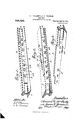
- Figure 1 is a perspective illustrating por tions of rails connected as contemplated by our invention
- Fig. 2 is a perspective inverted illustrating portions of rails connected as in Fig. 1
- Fig. 3 is a perspective of an end portion of a rail constructed according to our invention and showing the inside face thereof
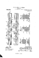
- Fig. 4 is an elevation illustrating end portions of rails united, the connecting bolts being omitted
- Fig. 5 is a sectional plan taken on the line 55 of Fig. t
- Fig. 6 is an enlarged, transverse, sectional elevation taken on the line 66 of Fig. 4
- Fig. 7 is a view similar to Fig. 6 taken on the line 77 of Fig. 4
- Fig. 8 is a view similar to Figs. 6 and 7 taken on the line 88 of Fig. 4.
- 1' and 2 designate body portions of the rails which are of ordinary construction.
- 5 and 6 designate integral extensions of the base flanges of the rails which are sub stantially of the same lengths as the ball extensions 3 and 4:.
- the webs of the rails are reduced to onehalf their thickness from their extremities to the shoulders 7 on their inside faces.
- the webs on their outside faces are provided with integral enlargements 8, which enlarged portions of the webs extend beyond the portions 3 and 4 of the balls 5 and 6 of the base flanges at their extremities and be yond the shoulders 7 at their inner ends.
- the base flanges 5 and 6 are provided with step-like cut away portions 10, 11, 12 and 18.
- i l designates ordinary connecting bolts and 15 ordinary nuts which are threaded to said bolts for connecting the adjoining ends of rails.
- the rail ends are spaced a slight distance apart so as to permit expansion and contraction of the rails. In this position it is obvious, that the slots 9 do not register and by such an arrangement the connecting bolts will have more room for longitudinal play in the slots.
- the integral base extensions 16 upon which the portions 8 rest.
- the extensions 16 are of a length sufficient to support the portions 8 in adjustments of the rail ends greaterthan the lengths of the slots 9 and, it is obvious that the extensions 16 are of Suficient length to permit of an adjustment between the first and second of the slots 9.
- Such construction permits the adjoining ends of the flanges of two rails to abut, and form a stop for each other, at a point in vertieal-alinement with the abutting ends of the balls of said rails, while, at the same time interfering in no way with the function of said extensions 16, which is a Very desirable construction in rail joints.
- the improved rail-joint comprising two adjoining rails having the usual balls, webs and flanges intermediate of the rail-ends; ball and web-extensions, the web-extensions 8 being reinforced to a greater thickness than that of the rail-webs; the ends of the adjacent balls and flanges cut off and abutting in.
Landscapes
- Engineering & Computer Science (AREA)
- Mechanical Engineering (AREA)
- Architecture (AREA)
- Civil Engineering (AREA)
- Structural Engineering (AREA)
- Joining Of Building Structures In Genera (AREA)
Description
s. H. MOGARTY & J. T. HINDMAN.
RAIL JOINT.
APPLICATION FILED MAY 26, 1910.
Patented July 18,1911.
2 8HEET8SEEET 1 UNITED STATES PTENT OFFICE.
SAMUEL I-I. MCCAR'IY AND JAMES T. I-IINDMAN, 0F GRAYVILLE, ILLINOIS, ASSIGNORS, BY DIRECT AND MESNE ASSIGNMENTS, OF ONE-FOURTH TO WILLIAM W. I-IALLAM, OF GRAYVILLE, ILLINOIS, AND ONE-FOURTH TO HORACE P. OWEN, OF NEW HAR- MONY, INDIANA.
RAIL-JOINT.
To all whom it may concern;
Be it known that we, SAMUEL H. Mo- CARTY and JAMES T. HINDMAN, citizens of the United States, and residents of Grayville, White county, Illinois, have invented certain new and useful Improvements in Rail-Joints, of which the following is a specification containing a full, clear. and exact description, reference being had to the accompanying drawings, forming a part hereof.
Our invention relates to improvements in the construction of the meeting end portions of rails and the like to adapt the same to be joined so as to provide a stable and rigid joint.
It is objective also to secure a continuous bearing of considerable length at the joint so as to prevent the rounding of the end portions of the rails and to obviate noises consequent to the employment of the common form of joint.
A. still further object of our invention is to construct the meeting end portions of rails so that they may be more rigidly connected and secured against vertical and lateral movement relative each other and may be capable of movements lengthwise relative each other to compensate for the shrinking and stretching of rails.
For the above purposes our invent-ion consists in certain novel features of construction and arrangement of parts as will be hereinafter more fully described, pointed out in the claim and illustrated by the accompanying drawings; in which:
Figure 1 is a perspective illustrating por tions of rails connected as contemplated by our invention; Fig. 2 is a perspective inverted illustrating portions of rails connected as in Fig. 1; Fig. 3 is a perspective of an end portion of a rail constructed according to our invention and showing the inside face thereof; Fig. 4: is an elevation illustrating end portions of rails united, the connecting bolts being omitted; Fig. 5 is a sectional plan taken on the line 55 of Fig. t; Fig. 6 is an enlarged, transverse, sectional elevation taken on the line 66 of Fig. 4; Fig. 7 is a view similar to Fig. 6 taken on the line 77 of Fig. 4; and Fig. 8 is a view similar to Figs. 6 and 7 taken on the line 88 of Fig. 4.
Referring by numerals to the accompany- Specification of Letters Patent.
Application filed May 26, 1910.
Patented July 18, 1911.-
Serial No. 563,588.
ing drawings: 1' and 2 designate body portions of the rails which are of ordinary construction.
8 and 4t designate integral extensions of the balls of the rails which extensions are each only half the thickness of the ball proper.
5 and 6 designate integral extensions of the base flanges of the rails which are sub stantially of the same lengths as the ball extensions 3 and 4:.
The webs of the rails are reduced to onehalf their thickness from their extremities to the shoulders 7 on their inside faces. The webs on their outside faces are provided with integral enlargements 8, which enlarged portions of the webs extend beyond the portions 3 and 4 of the balls 5 and 6 of the base flanges at their extremities and be yond the shoulders 7 at their inner ends.
9 designates slots formed in the enlarged web portions 8 which slots are preferably equidistances apart and in longitudinal alinement with each other.
The base flanges 5 and 6 are provided with step-like cut away portions 10, 11, 12 and 18.
i l designates ordinary connecting bolts and 15 ordinary nuts which are threaded to said bolts for connecting the adjoining ends of rails.
As shown in Fig. 5 of the drawings, the rail ends are spaced a slight distance apart so as to permit expansion and contraction of the rails. In this position it is obvious, that the slots 9 do not register and by such an arrangement the connecting bolts will have more room for longitudinal play in the slots.
To provide for bases of extra length for the portions 8 of the rails, we have provided the integral base extensions 16 upon which the portions 8 rest. The extensions 16 are of a length sufficient to support the portions 8 in adjustments of the rail ends greaterthan the lengths of the slots 9 and, it is obvious that the extensions 16 are of Suficient length to permit of an adjustment between the first and second of the slots 9.
For the reason that the parts 8 extend beyond the ends of the rails proper and rest upon the base flanges and are engaged by the underneath face of the balls of the adjoining rail, it is obvious that all vertical play of the rail ends is eliminated and that a joint for connecting the ends of the rail is provided of unusual length. The said eX- tensions 16, it will be noted, are so narrow that they do not extend out to the free edge of the flange 5 thereby leaving the adjacent end of the flange in vertical alinement with the adjacent end of the ball of the same rail. Such construction permits the adjoining ends of the flanges of two rails to abut, and form a stop for each other, at a point in vertieal-alinement with the abutting ends of the balls of said rails, while, at the same time interfering in no way with the function of said extensions 16, which is a Very desirable construction in rail joints.
e claim:
The improved rail-joint, comprising two adjoining rails having the usual balls, webs and flanges intermediate of the rail-ends; ball and web-extensions, the web-extensions 8 being reinforced to a greater thickness than that of the rail-webs; the ends of the adjacent balls and flanges cut off and abutting in. vertical-alinement; the free end of said web-extensions projecting beyond said abutting ends of said balls and flanges so as to rest upon the flange of the adjoining rail; and the flange-extensions 16, projecting in a direction opposite that of the adjacent free projecting web-ends beyond said flangeends, to support the adjoining reinforced web-extensions, and also arranged to permit the flanges of the two rails to abut in ver tical-alinement with the abutting ends of the balls, in combination with suitable fastening bolts.
In testimony whereof, we have signed our names to this specification, in presence of two subscribing witnesses.
SAMUEL H. MCCARTY. JAMES T. HINDh IAN. lVitnesses P. C. ar/runs, JAMES DUNCAN.
Copies of this patent may be obtained for five cents each, by addressing the Commissioner of Patents. Washington, D. C.
Priority Applications (1)
| Application Number | Priority Date | Filing Date | Title |
|---|---|---|---|
| US56356810A US998024A (en) | 1910-05-26 | 1910-05-26 | Rail-joint. |
Applications Claiming Priority (1)
| Application Number | Priority Date | Filing Date | Title |
|---|---|---|---|
| US56356810A US998024A (en) | 1910-05-26 | 1910-05-26 | Rail-joint. |
Publications (1)
| Publication Number | Publication Date |
|---|---|
| US998024A true US998024A (en) | 1911-07-18 |
Family
ID=3066354
Family Applications (1)
| Application Number | Title | Priority Date | Filing Date |
|---|---|---|---|
| US56356810A Expired - Lifetime US998024A (en) | 1910-05-26 | 1910-05-26 | Rail-joint. |
Country Status (1)
| Country | Link |
|---|---|
| US (1) | US998024A (en) |
-
1910
- 1910-05-26 US US56356810A patent/US998024A/en not_active Expired - Lifetime
Similar Documents
| Publication | Publication Date | Title |
|---|---|---|
| US998024A (en) | Rail-joint. | |
| US725216A (en) | Rail-joint. | |
| US1056660A (en) | Rail-joint. | |
| US350666A (en) | Thomas a | |
| US977652A (en) | Rail-joint. | |
| US1133593A (en) | Combined rail tie, chair, and joint. | |
| US1041823A (en) | Rail-joint. | |
| US838288A (en) | Rail-joint. | |
| US755151A (en) | Rail-joint. | |
| US1081878A (en) | Rail-joint. | |
| US1021580A (en) | Rail chair and joint. | |
| US709045A (en) | Rail-joint. | |
| US960428A (en) | Railway-joint. | |
| US804074A (en) | Rail-joint. | |
| US671916A (en) | Rail-joint. | |
| US773558A (en) | Rail-joint. | |
| US1027956A (en) | Rail-joint. | |
| US807720A (en) | Rail-joint. | |
| US1011371A (en) | Rail-joint. | |
| US1036891A (en) | Street and railway track structure. | |
| US796551A (en) | Rail-joint. | |
| US446161A (en) | Libbeus chilson | |
| US755449A (en) | Rail chair and joint. | |
| US639453A (en) | Railwya-joint. | |
| US790539A (en) | Rail-joint. |