US9979019B2 - Composite positive electrode active material, method of manufacturing the same, positive electrode including the composite positive electrode active material, and lithium secondary battery including the positive electrode - Google Patents
Composite positive electrode active material, method of manufacturing the same, positive electrode including the composite positive electrode active material, and lithium secondary battery including the positive electrode Download PDFInfo
- Publication number
- US9979019B2 US9979019B2 US14/920,968 US201514920968A US9979019B2 US 9979019 B2 US9979019 B2 US 9979019B2 US 201514920968 A US201514920968 A US 201514920968A US 9979019 B2 US9979019 B2 US 9979019B2
- Authority
- US
- United States
- Prior art keywords
- positive electrode
- active material
- electrode active
- composite positive
- precursor
- Prior art date
- Legal status (The legal status is an assumption and is not a legal conclusion. Google has not performed a legal analysis and makes no representation as to the accuracy of the status listed.)
- Active, expires
Links
Images


Classifications
-
- H—ELECTRICITY
- H01—ELECTRIC ELEMENTS
- H01M—PROCESSES OR MEANS, e.g. BATTERIES, FOR THE DIRECT CONVERSION OF CHEMICAL ENERGY INTO ELECTRICAL ENERGY
- H01M4/00—Electrodes
- H01M4/02—Electrodes composed of, or comprising, active material
- H01M4/36—Selection of substances as active materials, active masses, active liquids
- H01M4/48—Selection of substances as active materials, active masses, active liquids of inorganic oxides or hydroxides
- H01M4/52—Selection of substances as active materials, active masses, active liquids of inorganic oxides or hydroxides of nickel, cobalt or iron
- H01M4/525—Selection of substances as active materials, active masses, active liquids of inorganic oxides or hydroxides of nickel, cobalt or iron of mixed oxides or hydroxides containing iron, cobalt or nickel for inserting or intercalating light metals, e.g. LiNiO2, LiCoO2 or LiCoOxFy
-
- H—ELECTRICITY
- H01—ELECTRIC ELEMENTS
- H01M—PROCESSES OR MEANS, e.g. BATTERIES, FOR THE DIRECT CONVERSION OF CHEMICAL ENERGY INTO ELECTRICAL ENERGY
- H01M4/00—Electrodes
- H01M4/02—Electrodes composed of, or comprising, active material
- H01M4/36—Selection of substances as active materials, active masses, active liquids
- H01M4/48—Selection of substances as active materials, active masses, active liquids of inorganic oxides or hydroxides
- H01M4/485—Selection of substances as active materials, active masses, active liquids of inorganic oxides or hydroxides of mixed oxides or hydroxides for inserting or intercalating light metals, e.g. LiTi2O4 or LiTi2OxFy
-
- C—CHEMISTRY; METALLURGY
- C01—INORGANIC CHEMISTRY
- C01F—COMPOUNDS OF THE METALS BERYLLIUM, MAGNESIUM, ALUMINIUM, CALCIUM, STRONTIUM, BARIUM, RADIUM, THORIUM, OR OF THE RARE-EARTH METALS
- C01F5/00—Compounds of magnesium
-
- C—CHEMISTRY; METALLURGY
- C01—INORGANIC CHEMISTRY
- C01G—COMPOUNDS CONTAINING METALS NOT COVERED BY SUBCLASSES C01D OR C01F
- C01G31/00—Compounds of vanadium
-
- C—CHEMISTRY; METALLURGY
- C01—INORGANIC CHEMISTRY
- C01G—COMPOUNDS CONTAINING METALS NOT COVERED BY SUBCLASSES C01D OR C01F
- C01G53/00—Compounds of nickel
-
- C—CHEMISTRY; METALLURGY
- C01—INORGANIC CHEMISTRY
- C01G—COMPOUNDS CONTAINING METALS NOT COVERED BY SUBCLASSES C01D OR C01F
- C01G53/00—Compounds of nickel
- C01G53/40—Nickelates
- C01G53/42—Nickelates containing alkali metals, e.g. LiNiO2
- C01G53/44—Nickelates containing alkali metals, e.g. LiNiO2 containing manganese
- C01G53/50—Nickelates containing alkali metals, e.g. LiNiO2 containing manganese of the type [MnO2]n-, e.g. Li(NixMn1-x)O2, Li(MyNixMn1-x-y)O2
-
- H—ELECTRICITY
- H01—ELECTRIC ELEMENTS
- H01M—PROCESSES OR MEANS, e.g. BATTERIES, FOR THE DIRECT CONVERSION OF CHEMICAL ENERGY INTO ELECTRICAL ENERGY
- H01M10/00—Secondary cells; Manufacture thereof
- H01M10/05—Accumulators with non-aqueous electrolyte
- H01M10/052—Li-accumulators
- H01M10/0525—Rocking-chair batteries, i.e. batteries with lithium insertion or intercalation in both electrodes; Lithium-ion batteries
-
- H—ELECTRICITY
- H01—ELECTRIC ELEMENTS
- H01M—PROCESSES OR MEANS, e.g. BATTERIES, FOR THE DIRECT CONVERSION OF CHEMICAL ENERGY INTO ELECTRICAL ENERGY
- H01M4/00—Electrodes
- H01M4/02—Electrodes composed of, or comprising, active material
- H01M4/36—Selection of substances as active materials, active masses, active liquids
- H01M4/48—Selection of substances as active materials, active masses, active liquids of inorganic oxides or hydroxides
- H01M4/50—Selection of substances as active materials, active masses, active liquids of inorganic oxides or hydroxides of manganese
- H01M4/505—Selection of substances as active materials, active masses, active liquids of inorganic oxides or hydroxides of manganese of mixed oxides or hydroxides containing manganese for inserting or intercalating light metals, e.g. LiMn2O4 or LiMn2OxFy
-
- H—ELECTRICITY
- H01—ELECTRIC ELEMENTS
- H01M—PROCESSES OR MEANS, e.g. BATTERIES, FOR THE DIRECT CONVERSION OF CHEMICAL ENERGY INTO ELECTRICAL ENERGY
- H01M4/00—Electrodes
- H01M4/02—Electrodes composed of, or comprising, active material
- H01M4/36—Selection of substances as active materials, active masses, active liquids
- H01M4/58—Selection of substances as active materials, active masses, active liquids of inorganic compounds other than oxides or hydroxides, e.g. sulfides, selenides, tellurides, halogenides or LiCoFy; of polyanionic structures, e.g. phosphates, silicates or borates
- H01M4/582—Halogenides
-
- C—CHEMISTRY; METALLURGY
- C01—INORGANIC CHEMISTRY
- C01P—INDEXING SCHEME RELATING TO STRUCTURAL AND PHYSICAL ASPECTS OF SOLID INORGANIC COMPOUNDS
- C01P2002/00—Crystal-structural characteristics
- C01P2002/50—Solid solutions
-
- C—CHEMISTRY; METALLURGY
- C01—INORGANIC CHEMISTRY
- C01P—INDEXING SCHEME RELATING TO STRUCTURAL AND PHYSICAL ASPECTS OF SOLID INORGANIC COMPOUNDS
- C01P2002/00—Crystal-structural characteristics
- C01P2002/50—Solid solutions
- C01P2002/52—Solid solutions containing elements as dopants
-
- C—CHEMISTRY; METALLURGY
- C01—INORGANIC CHEMISTRY
- C01P—INDEXING SCHEME RELATING TO STRUCTURAL AND PHYSICAL ASPECTS OF SOLID INORGANIC COMPOUNDS
- C01P2002/00—Crystal-structural characteristics
- C01P2002/70—Crystal-structural characteristics defined by measured X-ray, neutron or electron diffraction data
-
- C—CHEMISTRY; METALLURGY
- C01—INORGANIC CHEMISTRY
- C01P—INDEXING SCHEME RELATING TO STRUCTURAL AND PHYSICAL ASPECTS OF SOLID INORGANIC COMPOUNDS
- C01P2004/00—Particle morphology
- C01P2004/01—Particle morphology depicted by an image
- C01P2004/03—Particle morphology depicted by an image obtained by SEM
-
- C—CHEMISTRY; METALLURGY
- C01—INORGANIC CHEMISTRY
- C01P—INDEXING SCHEME RELATING TO STRUCTURAL AND PHYSICAL ASPECTS OF SOLID INORGANIC COMPOUNDS
- C01P2004/00—Particle morphology
- C01P2004/60—Particles characterised by their size
- C01P2004/61—Micrometer sized, i.e. from 1-100 micrometer
-
- C—CHEMISTRY; METALLURGY
- C01—INORGANIC CHEMISTRY
- C01P—INDEXING SCHEME RELATING TO STRUCTURAL AND PHYSICAL ASPECTS OF SOLID INORGANIC COMPOUNDS
- C01P2006/00—Physical properties of inorganic compounds
- C01P2006/10—Solid density
-
- H—ELECTRICITY
- H01—ELECTRIC ELEMENTS
- H01M—PROCESSES OR MEANS, e.g. BATTERIES, FOR THE DIRECT CONVERSION OF CHEMICAL ENERGY INTO ELECTRICAL ENERGY
- H01M10/00—Secondary cells; Manufacture thereof
- H01M10/05—Accumulators with non-aqueous electrolyte
- H01M10/052—Li-accumulators
-
- Y—GENERAL TAGGING OF NEW TECHNOLOGICAL DEVELOPMENTS; GENERAL TAGGING OF CROSS-SECTIONAL TECHNOLOGIES SPANNING OVER SEVERAL SECTIONS OF THE IPC; TECHNICAL SUBJECTS COVERED BY FORMER USPC CROSS-REFERENCE ART COLLECTIONS [XRACs] AND DIGESTS
- Y02—TECHNOLOGIES OR APPLICATIONS FOR MITIGATION OR ADAPTATION AGAINST CLIMATE CHANGE
- Y02E—REDUCTION OF GREENHOUSE GAS [GHG] EMISSIONS, RELATED TO ENERGY GENERATION, TRANSMISSION OR DISTRIBUTION
- Y02E60/00—Enabling technologies; Technologies with a potential or indirect contribution to GHG emissions mitigation
- Y02E60/10—Energy storage using batteries
-
- Y—GENERAL TAGGING OF NEW TECHNOLOGICAL DEVELOPMENTS; GENERAL TAGGING OF CROSS-SECTIONAL TECHNOLOGIES SPANNING OVER SEVERAL SECTIONS OF THE IPC; TECHNICAL SUBJECTS COVERED BY FORMER USPC CROSS-REFERENCE ART COLLECTIONS [XRACs] AND DIGESTS
- Y02—TECHNOLOGIES OR APPLICATIONS FOR MITIGATION OR ADAPTATION AGAINST CLIMATE CHANGE
- Y02T—CLIMATE CHANGE MITIGATION TECHNOLOGIES RELATED TO TRANSPORTATION
- Y02T10/00—Road transport of goods or passengers
- Y02T10/60—Other road transportation technologies with climate change mitigation effect
- Y02T10/70—Energy storage systems for electromobility, e.g. batteries
-
- Y02T10/7011—
Definitions
- the present disclosure relates to a composite positive active material, a method of manufacturing the same, a positive electrode including the composite positive active material, and a lithium secondary battery including the positive electrode.
- the lithium battery that is used as the energy source of these devices desirably provides a high-voltage, high specific energy, and high-density.
- an improved positive active material which provides improved lifespan and capacity characteristics, and at the same time has a relaxed reduction in voltage characteristics upon repeated charge and discharge, is needed.
- a composite positive active material and a method of manufacturing the same, wherein the composite positive active material has improved structural stability and has improved electrochemical characteristics.
- a positive electrode including the composite positive active material.
- a lithium secondary battery including the positive electrode and having improved lifespan characteristics.
- a composite positive electrode active material includes: an overlithiated layered oxide (OLO) including vanadium (V) and magnesium (Mg), wherein the vanadium and the magnesium have a molar ratio of about 1:2.
- OLO overlithiated layered oxide
- V vanadium
- Mg magnesium
- a positive electrode includes the composite positive electrode active material.
- a lithium secondary battery includes the positive electrode.
- a method of manufacturing the composite positive electrode active material includes: mixing a metal precursor for forming an overlithiated layered oxide (OLO), a vanadium precursor which includes vanadium, and a magnesium precursor which includes magnesium to form a precursor mixture, wherein a molar ratio of the vanadium to the magnesium in the precursor mixture is about 1:2; drying the precursor mixture to form a dried mixture; mixing the dried mixture with a lithium precursor; and heat treating the dried mixture and the lithium precursor to manufacture the composite positive electrode active material.
- OLO overlithiated layered oxide
- FIG. 1 is an exploded perspective view of an embodiment of a lithium battery
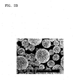
- FIGS. 2A and 2B are scanning electron microscope (SEM) images of a composite positive electrode active material prepared according to Example 1;
- FIGS. 3A and 3B are graphs of intensity (arbitrary units, a.u.) versus diffraction angle (degrees two-theta, 2 ⁇ ) showing results of X-ray diffraction (XRD) analysis of the composite positive electrode active material of Example 1 and the overlithiated layered oxide (OLO) of Comparative Example 1;
- XRD X-ray diffraction
- FIG. 4 is a graph of capacity (milliampere hours per gram, mAh/g) versus cycle number showing changes in the capacity of coin half-cells prepared according to Manufacturing Example 1 and Comparative Manufacturing Examples 1 to 3 over 40 cycles;
- FIG. 5 is a graph of capacity (milliampere hours per gram, mAh/g) versus cycle number showing changes in the capacity of coin half-cells prepared according to Manufacturing Example 1 and Comparative Manufacturing Examples 1, 4, and 5 over 40 cycles.
- first,” “second,” “third” etc. may be used herein to describe various elements, components, regions, layers and/or sections, these elements, components, regions, layers and/or sections should not be limited by these terms. These terms are only used to distinguish one element, component, region, layer or section from another element, component, region, layer or section. Thus, “a first element,” “component,” “region,” “layer” or “section” discussed below could be termed a second element, component, region, layer or section without departing from the teachings herein.
- relative terms such as “lower” or “bottom” and “upper” or “top,” may be used herein to describe one element's relationship to another element as illustrated in the Figures. It will be understood that relative terms are intended to encompass different orientations of the device in addition to the orientation depicted in the Figures. For example, if the device in one of the figures is turned over, elements described as being on the “lower” side of other elements would then be oriented on “upper” sides of the other elements. The exemplary term “lower,” can therefore, encompasses both an orientation of “lower” and “upper,” depending on the particular orientation of the figure.
- “About” or “approximately” as used herein is inclusive of the stated value and means within an acceptable range of deviation for the particular value as determined by one of ordinary skill in the art, considering the measurement in question and the error associated with measurement of the particular quantity (i.e., the limitations of the measurement system). For example, “about” can mean within one or more standard deviations, or within ⁇ 30%, 20%, 10% or 5% of the stated value.
- Exemplary embodiments are described herein with reference to cross section illustrations that are schematic illustrations of idealized embodiments. As such, variations from the shapes of the illustrations as a result, for example, of manufacturing techniques and/or tolerances, are to be expected. Thus, embodiments described herein should not be construed as limited to the particular shapes of regions as illustrated herein but are to include deviations in shapes that result, for example, from manufacturing. For example, a region illustrated or described as flat may, typically, have rough and/or nonlinear features. Moreover, sharp angles that are illustrated may be rounded. Thus, the regions illustrated in the figures are schematic in nature and their shapes are not intended to illustrate the precise shape of a region and are not intended to limit the scope of the present claims.
- a composite positive electrode active material including an overlithiated layered oxide (OLO) in which vanadium (V) and magnesium (Mg) have a molar ratio of about 1:2.
- a molar content of lithium in the overlithiated layered oxide is greater than an anion content, wherein the anion content is a total molar content of F, Cl, Br, and I, if present, and one half of a molar content of oxygen and sulfur, if present.
- the composite positive electrode active material may include V 5+ and Mg 2+ at a molar ratio of about 1:2, e.g., about 0.9:2 to about 1.1:2, about 0.95:2 to about 1.05:2, or about 0.99:2 to about 1.01:2.
- the average oxidation number of a cation-doping element becomes about +3, and thus the stability of the composite positive electrode active material may be increased when it is doped and has a layered structure.
- the doping with such complex elements, e.g., V and Mg may improve lifespan characteristics by inhibiting capacity reduction caused by charge and discharge and by inhibiting changes in the discharge profile during high-voltage operation.
- the charge balance of the composite positive electrode active material may not be in neutral, and thus the composite positive electrode active material may be structurally unstable.
- the composite positive electrode active material may be a compound represented by Formula 1 below.
- Formula 1 In Formula 1, 1.0 ⁇ a ⁇ 1.4, 0 ⁇ x ⁇ 1, 0 ⁇ y ⁇ 1, 0 ⁇ z ⁇ 1, 0 ⁇ b ⁇ 1, 0 ⁇ c ⁇ 1, 0 ⁇ x+y+z+b+2b+c ⁇ 1, 0 ⁇ e ⁇ 1, and 0 ⁇ f ⁇ 1;
- M may be at least one selected from gallium (Ga), silicon (Si), tungsten (W), molybdenum (Mo), iron (Fe), chromium (Cr), copper (Cu), zinc (Zn), titanium (Ti), aluminum (Al), and boron (B); and
- M′ may be at least one selected from F, Cl, Br, and I.
- b denotes a stoichiometric ratio of V, and may be in a range from about 0.001 to about 0.03, e.g., about 0.002 to about 0.02, or about 0.005 to about 0.01. In another embodiment, b in Formula 1 may be in a range from about 0.0017 to about 0.008.
- the overlithiated layered oxide (OLO) may be structurally stabilized to an oxidation-reduction reaction during the charge and discharge. Accordingly, the lifespan characteristics of the lithium secondary battery may be improved during high-voltage operation.
- the composite positive electrode active material may include a high Mn amount of at least 40 mole percent (mol %), or at least 50 mol %, such as 40 mol % to 60 mol %, based on a total moles of Ni Co, Mn, V, Mg, and M, and, while not wanting to be bound by theory, it is understood that inclusion of such a high amount of Mn and lithium may result in a battery having improved capacity.
- the cationic dopants e.g., V and Mg
- the cationic dopants may be included in a crystal structure of the overlithiated layered oxide at a position of a transition metal, e.g., at least one selected from Ni, Co, and Mn, and the S and M′, if present, may be included at a position of an oxygen in the crystal structure of the overlithiated layered oxide.
- the compound of Formula 1 may be, for example, a compound represented by Formula 2 below: Li a Ni x Co y Mn z V b Mg 2b M c O 2 .
- Formula 2 Li a Ni x Co y Mn z V b Mg 2b M c O 2 .
- M may be at least one selected from Ga, Si, W, Mo, Fe, Cr, Cu, Zn, Ti, Al, and B.
- An example of the compound of Formula 2 may be a compound represented by Formula 3 below: Li a Ni x Co y Mn z V b Mg 2b O 2 .
- Formula 3 Li a Ni x Co y Mn z V b Mg 2b O 2 .
- b may be in a range from about 0.001 to about 0.03, e.g., about 0.005 to about 0.01, or may be in a range from about 0.0017 to about 0.008.
- the composite positive electrode active material may be of the formula Li 1.167 Ni 0.181 Co 0.125 Mn 0.515 V 0.004 Mg 0.008 O 2 , Li 1.167 Ni 0.175 Co 0.125 Mn 0.508 V 0.008 Mg 0.016 O 2 , or Li 1.167 Ni 0.163 Co 0.125 Mn 0.496 V 0.017 Mg 0.034 O 2 .
- the composite positive electrode active material may comprise particles having any suitable shape, and in a preferred embodiment comprises spherical particles.
- a primary particle of the composite positive electrode active material may have an average diameter (D 50 ) in a range from about 100 nanometers (nm) to about 250 nm, about 120 nm to about 230 nm, or about 140 nm to about 200 nm, and a secondary particle of the composite positive electrode active material may have an average diameter D 50 in a range from about 2 ⁇ m to about 20 ⁇ m, e.g., about 2 ⁇ m to about 12 ⁇ m, or about 5 ⁇ m to about 12 ⁇ m.
- the term “average diameter D 50 ” refers to a value of particle diameters measured at 50 volume % of the cumulative volume in particle diameter distribution. When the average particle diameter D 50 is within the foregoing range, an electrode plate manufacturing process may be more easily performed.
- X-ray diffraction (XRD) analysis may confirm that the composite positive electrode active material has an OLO structure
- ICP analysis may determine a composition of each constituent element, e.g., the amounts of V and Mg.
- peaks appearing at a Bragg 2 ⁇ angle between 36.85° and 36.95° correspond to a (101) plane of LiMeO 2 (e.g., LiNiCoMnO 2 ) that constitutes a layered structure.
- the composite positive electrode active material may have a powder density in a range from about 2.4 grams per cubic centimeter (g/cm 3 ) to about 3.0 g/cm 3 .
- a lithium battery may have improved voltage and lifespan characteristics.
- the composite positive electrode active material may be manufactured by a method comprising: mixing a metal precursor for forming an overlithiated layered oxide (OLO), a vanadium precursor which comprises vanadium, and a magnesium precursor which comprises magnesium to form a precursor mixture, wherein a molar ratio of the vanadium to the magnesium in the precursor mixture is about 1:2; drying the precursor mixture to form a dried mixture; mixing the dried mixture with a lithium precursor; and heat treating the dried mixture and the lithium precursor to manufacture the composite positive electrode active material.
- OLO overlithiated layered oxide
- the method may comprise obtaining a mixture of precursors by mixing a metal precursor for forming an OLO, a V precursor, and a Mg precursor; a second step of dispersing and drying the resultant mixture; and a third step of mixing the dried mixture with a lithium precursor and performing a heat treatment thereon.
- the metal precursor for forming the OLO may include a Ni precursor which comprises Ni, a Mn precursor which comprises Mn, and a Co precursor which comprises Co.
- a solvent may be used to obtain a precursor mixture.
- Any suitable solvent may be used.
- Representative solvents include alcohols (e.g., methanol, ethanol, butanol); water; liquid carbon dioxide; aldehydes (e.g., acetaldehydes, propionaldehydes), formamides (e.g., N, N-dimethylformamide); ketones (e.g., acetone, methyl ethyl ketone, ⁇ -bromoethyl isopropyl ketone); acetonitrile; sulfoxides (e.g., dimethylsulfoxide, diphenylsulfoxide, ethyl phenyl sulfoxide); sulfones (e.g., diethyl sulfone, phenyl 7-quinolylsulfone); thiophenes (e.g., thiophenes (e.g., thiophen
- the solvent may be water or an alcohol-based solvent, and the alcohol-based solvent may be ethanol.
- An amount of the solvent used herein may be in a range from about 200 parts by weight to about 3,000 parts by weight, based on 100 parts by weight of a total amount of the metal precursor, the V precursor, and the Mg precursor. When the amount of the solvent is within the range above, a mixture in which each of the precursors is evenly mixed may be obtained. Such a mixing may be performed at a temperature from about 20° C. to about 80° C., e.g., at a temperature of about 60° C.
- the starting material comprising a transition metal e.g., Ni, Co, and Mn
- a cationic dopant e.g., the V precursor and the Mg precursor
- the primary particles of the composite positive electrode active material may be more evenly formed.
- Ni precursor, the Mn precursor, and the Co precursor may each independently be an acetate, nitrate, hydroxide, oxide, or sulfate, each of which may include at least one selected from Ni, Mn, and Co, but they are not limited thereto.
- the V precursor and the Mg precursor may each independently be a nitrate, acetate, oxide, or sulfate, each of which includes V and/or Mg, but they are not limited thereto.
- the V precursor may be, for example, at least one selected from NH 4 VO 3 , V 2 O 5 , and VCl 3 .
- the Mg precursor may be, for example, at least one selected from Mg(OH) 2 , Mg(SO 4 ), and MgCl 2 .
- the V precursor and the Mg precursor may be included in a range from about 0.1 mole percent (mol %) to about 3 mol %, e.g., about 0.2 mol % to about 2 mol %, or about 0.5 mol % to about 1 mol %, based on a total amount of the transition metal of the composite positive electrode active material.
- a molar ratio of the V precursor to the Mg precursor may be about 1:2, e.g., about 0.9:2 to about 1.1:2, about 0.95:2 to about 1.05:2, or about 0.99:2 to about 1.01:2.
- an average oxidation number of V and Mg in the composite positive electrode active material may be about +3, and accordingly, the composite positive electrode active material may maintain overall charge neutrality of about 0, so as to adapt for the charge balance.
- the OLO may be structurally stabilized.
- the charge and discharge capacity of the lithium secondary battery may be increased, and accordingly, the lifespan characteristics of the lithium secondary battery may be improved upon high-voltage operation.
- the precursor mixture may be dispersed, and the step of dispersing may be performed by milling.
- the milling may be performed by using a ball mall or a bead mill, but is not limited thereto.
- the precursor mixture after the dispersing may have an average diameter in a range from about 5 nm to about 100 nm, e.g., about 10 nm to about 50 nm. When the average particle diameter of the precursor mixture is within the foregoing range, an electrode plate manufacturing process may be more easily performed.
- a solvent such as an alcohol-based solvent, e.g., ethanol, may be used to increase a mixing efficiency.
- An amount of the solvent may be in a range from about 100 parts by weight to about 3,000 parts by weight, based on 100 parts by weight of a total amount of the precursors. When the amount of the solvent is within the foregoing range, a mixture in which the precursors are evenly dispersed may be result.
- the dispersion may be conducted for any suitable time, and may be performed for about 20 minutes to about 10 hours, e.g., about 1 hour to about 3 hours or about 30 minutes to about 1 to 2 hours.
- the dispersion time is within the foregoing range, the precursors and the doping materials may be evenly dispersed in a very small size, resulting in improved properties.
- the drying e.g. spray-drying
- the drying may be performed at a rate in a range from about 5 millimeters per minute (mm/min) to about 30 mm/min, e.g., about 10 mm/min to about 15 mm/min.
- the spray-drying may be performed at a temperature of about 150° C. to about 300° C., e.g., 150° C. to about 300° C.
- a precursor in which the transition metal materials and the cationic doping material are evenly mixed may be result. Accordingly, the doping materials may be evenly doped with a crystalline structure.
- the lithium precursor may be, for example, at least one selected from lithium carbonate (Li 2 CO 3 ), lithium sulfate (Li 2 SO4), lithium nitrate (LiNO 3 ), and lithium hydroxide (LiOH).
- the amount of the lithium precursor is stoichiometrically selected to provide a composition of the composite positive electrode active material of Formula 1.
- the heat treatment may be performed at a temperature of about 600° C. to about 900° C., e.g., about 700° C. to about 750° C.
- the heat treatment time may be selected according to the heat treatment temperature.
- the heat treatment may be formed in air or under a nitrogen atmosphere for about 5 hours to about 15 hours, e.g., about 10 hours to about 12 hours.
- the lithium compound may be, for example, at least one selected from Li 2 CO 3 , Li 2 SO 4 , LiNO 3 , and LiOH.
- the lithium compound may be combined with the precursor mixture to provide a stoichiometric composition of the composite positive electrode active material of Formula 1.
- an anionic doping material precursor may be further used to provide S and/or M′ in Formula 1.
- an amount of the anionic doping material precursor may be stoichiometrically selected to provide a composition of the composite positive electrode active material of Formula 1.
- the anionic doping material may comprise at least one selected from F, S, Cl, Br, and I, and may comprise at least one selected from LiF, Li 2 S, LiCl, and LiBr.
- a preferred example of the anionic doping material is LiF, but the anionic doping material is not limited thereto.
- a coating layer may be formed on the composite positive electrode active material.
- the inclusion of such a coating layer may lead to the improvement of charge and discharge characteristics, lifespan characteristics, and high-voltage characteristics of a lithium battery when a positive electrode including the composite positive electrode active material is used in the lithium battery.
- the coating layer may include a carbonaceous material, such as carbon nanotube, fullerene, graphene, and carbon fiber, a conductive polymer, such as polyaniline, polythiophene, or polypyrrole, a metal oxide, such as silica (SiO 2 ), alumina (Al 2 O 3 ), a zirconium oxide (ZrO 2 ), or a titanium oxide (TiO 2 ), and a metal, such as would be provided by AlF 3 , CsF, KF, LiF, NaF, RbF, or TiF.
- a carbonaceous material such as carbon nanotube, fullerene, graphene, and carbon fiber
- a conductive polymer such as polyaniline, polythiophene, or polypyrrole
- a metal oxide such as silica (SiO 2 ), alumina (Al 2 O 3 ), a zirconium oxide (ZrO 2 ), or a titanium oxide (TiO 2 )
- a positive electrode including the composite positive electrode active material.
- a lithium secondary battery including the positive electrode.
- the positive electrode active materials that are known in the art may be used in addition to the composite positive electrode active material described above.
- the additional positive electrode active materials may be at least one selected from a lithium-cobalt oxide, a lithium-nickel-cobalt-Manganese oxide, a lithium-nickel-cobalt-aluminum oxide, a lithium-iron-phosphours oxide, and a lithium-manganese oxide, but is not limited thereto. Any suitable material available as a positive electrode active material in the art may be used.
- the first electrode active material may include a compound represented by one of the formulas, e.g., Li a A 1 ⁇ b B′ b D 2 (wherein 0.90 ⁇ a ⁇ 1.8 and 0 ⁇ b ⁇ 0.5); Li a E 1 ⁇ b B′ b O 2 ⁇ c D c (wherein, 0.90 ⁇ a ⁇ 1.8, 0 ⁇ b ⁇ 0.5, and 0 ⁇ c ⁇ 0.05); LiE 2 ⁇ b B′ b O 4 ⁇ c D c (wherein, 0 ⁇ b ⁇ 0.5 and 0 ⁇ c ⁇ 0.05); Li a Ni 1 ⁇ b ⁇ c Co b B′ c D ⁇ (wherein, 0.90 ⁇ a ⁇ 1.8, 0 ⁇ b ⁇ 0.5, 0 ⁇ c ⁇ 0.05, and 0 ⁇ 2); Li a Ni 1 ⁇ b ⁇ c Co b B′ c O 2 ⁇ F′ ⁇ (wherein, 0.90 ⁇ a ⁇ 1.8, 0 ⁇ b ⁇ 0.5, 0 ⁇ c ⁇ 0.05, and 0 ⁇ 2); Li a Ni 1 ⁇ b ⁇ c Co b B′ c O 2
- A may be Ni, Co, Mn, or a combination thereof;
- B′ may be Al, Ni, Co, Mn, Cr, Fe, Mg, Sr, V, a rare-earth element, or a combination thereof;
- D may be O, F, S, P, or a combination thereof;
- E may be Co, Mn, or a combination thereof;
- F′ may be F, S, P, or a combination thereof;
- G may be Al, Cr, Mn, Fe, Mg, La, Ce, Sr, V, or a combination thereof;
- Q may be Ti, Mo, Mn, or a combination thereof;
- a positive electrode may be prepared as follows.
- a positive electrode active material composition in which a positive active material, a binder, and a solvent are mixed is prepared.
- a conductive agent may be further added to the positive electrode active material composition.
- the positive electrode active material composition may be directly coated and dried on a metal collector, so as to prepare a positive electrode plate.
- the positive electrode active material composition may be cast on a separate support, and then, a film exfoliated from the support is laminated on a metal collector, so as to prepare a positive electrode plate.
- the composite positive electrode active material As a positive electrode active material, the composite positive electrode active material according to an exemplary embodiment may be used. In addition to the composite positive electrode active material described above, a first electrode active material that is used in a lithium secondary battery may be further included.
- the first positive electrode active material may include at least one selected from a lithium-cobalt oxide, a lithium-nickel-cobalt-manganese oxide, a lithium-nickel-cobalt-aluminum oxide, a lithium-iron-phosphours oxide, and a lithium-manganese oxide, but is not limited thereto. Any suitable material available as a positive electrode active material in the art may be used.
- a conductive agent, a binder, and a solvent used in the positive electrode active material composition may be identical to those used in a negative electrode active material composition.
- a plasticizer may be further added to the positive electrode active material composition and/or the negative electrode active material composition, so as to prepare pores in electrode plates.
- Amounts of the positive electrode active material, the conductive agent, the binder, and the solvent may be determined by one of skill in the art without undue experimentation. According to use and configuration of the lithium battery, at least one of the conductive agent, the binder, and the solvent may be omitted.
- a negative electrode may be prepared in the substantially same manner, except in preparing the positive electrode, a negative electrode active material is used instead of a positive electrode active material.
- the negative electrode active material may include at least one selected from a carbonaceous material, silicone, a silicon oxide, a silicon-based alloy, a silicon-carbonaceous composite, tin, a tin-based alloy, a tin-carbon composite, and a metal oxide.
- the carbonaceous material may include crystalline carbon, amorphous carbon, or a mixture thereof.
- the crystalline carbon may be natural or artificial graphite of shapeless, plate, flake, sphere, or fiber form.
- the amorphous carbon may be soft carbon (low-temperature sintered carbon), hard carbon, a mesophase pitch carbide, sintered coke, graphene, carbon black, fullerene soot, carbon nanotube, carbon fiber, or the like, but is not limited thereto. Any suitable material available as the negative active material in the art may be used.
- the negative electrode active material may be at least one selected from the group consisting of SiO x (0 ⁇ x ⁇ 2, e.g., 0.5 to 1.5), Sn, SnO 2 , a mixture of silicon-containing metal alloy, and a mixture thereof.
- the metal capable of forming the silicon alloy may be at least one selected from the group consisting of Al, Sn, Ag, Fe, Bi, Mg, Zn, in, Ge, Pb, and Ti.
- the negative electrode active material may comprise at least one selected from a metal and/or metalloid that is alloyable with lithium, an alloy of the metal and/or metalloid, and an oxide of the metal and/or metalloid.
- the metal and/or metalloid that is alloyable with lithium may be Si, Sn, Al, Ge, Pb, Bi, a SbSi—Y′ alloy (where Y′ is an alkali metal, an alkaline earth metal, a Group 13 element, a Group 14 element, a transition metal, a rare-earth element, or a combination thereof and is not Si), a Sn—Y′′ alloy (where Y′′ is an alkali metal, an alkaline earth metal, a Group 13 element, a Group 14 element, a transition metal, a rare-earth element, or a combination thereof and is not Sn), or MnO x (0 ⁇ x ⁇ 2).
- the element Y′ and Y′′ may each independently be Mg, Ca, Sr, Ba, Ra, Sc, Y, Ti, Zr, Hf, Rf, V, Nb, Ta, Db, Cr, Mo, W, Sg, Tc, Re, Bh, Fe, Pb, Ru, Os, Hs, Rh, Ir, Pd, Pt, Cu, Ag, Au, Zn, Cd, B, Al, Ga, Sn, In, Ti, Ge, P, As, Sb, Bi, S, Se, Te, Po, or a combination thereof.
- the oxide of the metal/metalloids may be a lithium titanium oxide, a vanadium oxide, a lithium vanadium oxide, SnO 2 , or SiO x (0 ⁇ x ⁇ 2).
- the negative electrode active material may include at least one element selected from the group consisting of a Group 13 element, a Group 14 element, and a Group 15 element of the periodic table.
- the negative electrode active material may include at least one element selected from the group consisting of Si, Ge, and Sn.
- Amounts of the negative electrode active material, the conductive agent, the binder, and the solvent may be determined by one of skill in the art without undue experimentation.
- a separator is disposed between the positive electrode and the negative electrode, and may use an insulating-thin film that has high ion permeability and mechanical strength.
- the separator may have a pore diameter in a range from about 0.01 ⁇ m to about 10 ⁇ m and a thickness in a range from about 5 ⁇ m to about 20 ⁇ m.
- the separator having a pore diameter and a thickness within these ranges may be an olefin polymer, such as polypropylene; a sheet or a non-woven fabric including glass fibers or polyethylene.
- the solid polymeric electrolyte may also serve as a separation.
- the olefin polymer examples include polyethylene, polypropylene, and polyvinylidene fluoride, and the olefin polymer may have a multilayer structure including two or more polymer layers. That is, the separator may have a mixed multilayer structure, such as a two-layer separator of polyethylene/polypropylene, a three-layer separator of polyethylene/polypropylene/polyethylene, and a three-layer separator of polypropylene/polyethylene/polypropylene.
- a lithium salt-containing non-aqueous electrolyte may comprise a non-aqueous electrolyte and a lithium salt.
- the non-aqueous electrolyte may be a non-aqueous electrolytic solution, an organic solid electrolyte, or an inorganic solid electrolyte.
- the non-aqueous electrolytic solution may include an organic solvent, and any suitable material available as the organic solvent in the art may be used.
- the organic solvent may be propylene carbonate, ethylene carbonate, fluoroethylene carbonate, butylene carbonate, dimethyl carbonate, diethyl carbonate, methylethyl carbonate, methylpropyl carbonate, ethylpropyl carbonate, methylisopropyl carbonate, dipropylcarbonate, dibutyl carbonate, fluoroethylene carbonate, benzonitrile, acetonitrile, tetrahydrofuran, 2-methyltetrahydrofuran, ⁇ -butyrolactone, dioxolane, 4-methyldioxolane, N-dimethylformamide, N,N-dimethylacetamide, N,N-dimethylsulfoxide, dioxane, 1,2-dimethoxyethane, sulforane, dichloroethane, chlorobenzen
- the organic solid electrolyte may be, for example, a polyethylene derivative, a polyethylene oxide derivative, a polypropylene oxide derivative, a phosphate ester polymer, polyagitation lysine, polyester sulfide, polyvinyl alcohol, polyvinylidene fluoride, or a polymer containing an ionic dissociable group.
- the inorganic solid electrolyte may be, for example, a Li-based nitride, such as Li 3 N, LiI, Li 5 NI 2 , Li 3 N—LiI—LiOH, Li 2 SiS 3 , Li 4 SiO 4 , Li 4 SiO 4 —LiI—LiOH, Li 3 PO 4 —Li 2 S—SiS 2 , a halogenide, or a sulfate.
- a Li-based nitride such as Li 3 N, LiI, Li 5 NI 2 , Li 3 N—LiI—LiOH, Li 2 SiS 3 , Li 4 SiO 4 , Li 4 SiO 4 —LiI—LiOH, Li 3 PO 4 —Li 2 S—SiS 2 , a halogenide, or a sulfate.
- the lithium salt is a material that is easily dissolved in the non-aqueous electrolyte, and examples thereof include LiPF 6 , LiBF 4 , LiSbF 6 , LiAsF 6 , LiClO 4 , LiCF 3 SO 3 , Li(CF 3 SO 2 ) 2 N, LiC 4 F 9 SO 3 , LiAlO 2 , LiAlCl 4 , LiN(C x F 2x+1 SO 2 )(C y F 2y+1 SO 2 ) (where x and y are each independently a natural number), LiCl, LiI, or a mixture thereof.
- the non-aqueous electrolyte may further include, for example, pyridine, triethylphosphate, triethanolamine, cyclic ether, ethylenediamine, n-glyme, hexaphosphoric triaminde, nitrobenzene derivative, sulfur, quinoneimine dye, N-substituted oxazolidinone, N,N-substituted imidazolidine, ethylene glycol dialkyl ether, ammonium salt, pyrrole, 2-methoxy ethanol, or aluminum trichloride.
- a halogen-containing solvent such as carbon tetrachloride or ethylene trifluoride, may be further used.
- a lithium secondary battery 11 includes a positive electrode 13 , a negative electrode 12 , and a separator 34 .
- the positive electrode 13 , the negative electrode 12 , and the separator 14 are wound or folded to be accommodated in a battery case 15 .
- an organic electrolytic solution is loaded into the battery case 15 , and then, sealed with a cap assemble 16 , thereby completing the preparation of the lithium battery 11 .
- the battery case 15 may be cylindrical, rectangular, or thin film-shaped.
- the lithium battery 11 may be a thin film-type battery.
- the lithium battery 11 may be a lithium ion battery.
- the separator 14 is disposed between the positive electrode 13 and the negative electrode 14 to form a battery assembly.
- a plurality of battery assemblies are stacked in a bi-cell structure, and then impregnated with an organic electrolytic solution, and the obtained structure is housed in a pouch, and then, sealed, thereby completing the preparation of a lithium ion polymer battery.
- a plurality of the battery assemblies may be stacked on each other to form a battery pack, and the battery pack may be used in various devices that require high capacity and high output functions.
- the battery pack may be used in a laptop, a smart phone, or an electric vehicle.
- the lithium battery according to an exemplary embodiment has high-rate characteristics and excellent lifespan characteristics, and thus may be suitable to be applied to electric vehicles (EVs), e.g., a hybrid vehicle such as a plug-in hybrid electric vehicle (PHEV).
- EVs electric vehicles
- PHEV plug-in hybrid electric vehicle
- a mixture of Ni(OH) 2 , Co(OH) 2 , Mn 3 O 4 , NH 4 VO 3 , and Mg(OH) 2 was added to distilled water, and then, evenly dispersed therein for 2 hours using a ball mill (including a ZrO 2 ball having a 0.3 mm particle diameter) to obtain a composition for forming a composite positive electrode active material.
- a molar ratio of Li 2 MnO 3 :Li(NiCoMnVMg)O 2 was adjusted to 40:60, a molar ratio of Ni:Co:Mn was adjusted to 22.5:15.0:62.5, and a total molar ratio of i) lithium and ii) a mixture of manganese, nickel and cobalt was adjusted to 1.40:1.00.
- Such starting materials i.e., Ni(OH) 2 , Co(OH) 2 , Mn 3 O 4 , NH 4 VO 3 , and Mg(OH) 2 , were mixed to provide a stoichiometric composite positive electrode active material of the formula Li 1.167 Ni 0.181 Co 0.125 Mn 0.515 V 0.004 Mg 0.008 O 2 , wherein amounts of NH 4 VO 3 and Mg(OH) 2 were determined when the amount of vanadium was 0.5 mol % and the amount of magnesium was 1.0 mol %, based on the total amount (1.0 mol) of the transition metals in the composite positive electrode active material.
- the prepared composition for forming a composite positive electrode active material was subjected to a spray-drying method at a temperature of 245° C. at a rate of 15 millimeters per minute (mm/min), so as to obtain a precursor doped with vanadium and magnesium. Then, the precursor was mixed with Li 2 CO 3 according to a solid-state synthesis method. The resultant mixture was heat-treated in air for 10 hours at a temperature of 700° C., thereby manufacturing a composite positive electrode active material of the formula Li 1.167 Ni 0.181 Co 0.125 Mn 0.515 V 0.004 Mg 0.008 O 2 .
- a composite positive electrode active material was manufactured in the same manner as in Example 1, except that in preparing a composition for forming a composite positive electrode active material, the same starting materials, i.e., Ni(OH) 2 , Co(OH) 2 , Mn 3 O 4 , NH 4 VO 3 , and Mg(OH) 2 , were mixed to provide a stoichiometric composite positive electrode active material of the formula Li 1.167 Ni 0.175 Co 0.125 Mn 0.508 V 0.008 Mg 0.016 O 2 , wherein amounts of NH 4 VO 3 and Mg(OH) 2 were determined so that the amount of vanadium was 1.0 mol % and the amount of magnesium was 2.0 mol %, based on the total amount (1.0 mol) of the transition metals in the composite positive electrode active material.
- the same starting materials i.e., Ni(OH) 2 , Co(OH) 2 , Mn 3 O 4 , NH 4 VO 3 , and Mg(OH) 2 , were
- a composite positive electrode active material was manufactured in the same manner as in Example 1, except that in preparing a composition for forming a composite positive electrode active material, the same starting materials, i.e., Ni(OH) 2 , Co(OH) 2 , Mn 3 O 4 , NH 4 VO 3 , and Mg(OH) 2 , were mixed to provide a stoichiometric composite positive electrode active material of the formula Li 1.167 Ni 0.163 Co 0.125 Mn 0.496 V 0.017 Mg 0.034 O 2 , wherein amounts of NH 4 VO 3 and Mg(OH) 2 were determined when the amount of vanadium was 2.0 mol % and the amount of magnesium was 4.0 mol %, based on the total amount (1.0 mol) of the transition metals in the composite positive electrode active material.
- the same starting materials i.e., Ni(OH) 2 , Co(OH) 2 , Mn 3 O 4 , NH 4 VO 3 , and Mg(OH) 2 , were mixed
- a composite positive electrode active material of the formula Li 1.167 Ni 0.188 Co 0.125 Mn 0.521 O 2 was manufactured in the same manner as in Example 1, except that in preparing a composition for forming a composite positive electrode active material, NH 4 VO 3 and Mg(OH) 2 were not used as starting materials.
- a composite positive electrode active material of the formula Li 1.167 Ni 0.185 Co 0.125 Mn 0.519 V 0.0042 O 2 was manufactured in the same manner as in Example 1, except that in preparing a composition for forming a composite positive electrode active material, Mg(OH) 2 was not used as a starting material, and Ni(OH) 2 , Co(OH) 2 , Mn 3 O 4 , and NH 4 VO 3 were mixed to provide a stoichiometric composite positive electrode active material of the formula Li 1.167 Ni 0.185 Co 0.125 Mn 0.519 V 0.0042 O 2 , wherein the amount of NH 4 VO 3 was determined so that the amount of vanadium was 0.5 mol %, based on the total amount (1.0 mol) of the transition metals in the composite positive electrode active material.
- a composite positive electrode active material of the formula Li 1.167 Ni 0.183 Co 0.125 Mn 0.517 Mg 0.0083 O 2 was manufactured in the same manner as in Example 1, except that in preparing a composition for forming a composite positive electrode active material, NH 4 VO 3 was not used as a starting material, and Ni(OH) 2 , Co(OH) 2 , Mn 3 O 4 , and Mg(OH) 2 were mixed to provide a stoichiometric composite positive electrode active material of the formula Li 1.167 Ni 0.183 Co 0.125 Mn 0.517 Mg 0.0083 O 2 , wherein the amount of NH 4 VO 3 was determined so that the amount of magnesium was 1.0 mol %, based on the total amount (1.0 mol) of the transition metals in the composite positive electrode active material.
- a composite positive electrode active material was manufactured in the same manner as in Example 1, except that in preparing a composition for forming a composite positive electrode active material, amounts of NH 4 VO 3 and Mg(OH) 2 were determined so that the amount of vanadium was 0.5 mol % and the amount of magnesium was 0.5 mol %, based on the total amount (1.0 mol) of the transition metals in the composite positive electrode active material.
- a composite positive electrode active material was manufactured in the same manner as in Example 1, except that in preparing a composition for forming a composite positive electrode active material, amounts of NH 4 VO 3 and Mg(OH) 2 were determined so that the amount of vanadium was 1.0 mol % and the amount of magnesium was 0.5 mol %, based on the total amount (1.0 mol) of the transition metals in the composite positive electrode active material.
- Example 2 92 wt % of the composite positive electrode active material of Example 1, 4 wt % of polyvinylidene fluoride (PVDF), and 4 wt % of acetylene black were mixed together, and then, the mixture was dispersed in N-methyl-2-pyrrolidone, so as to manufacture a slurry. Next, an aluminum foil having a thickness of 15 ⁇ m was coated with the slurry, and then, dried, so as to manufacture a positive electrode.
- PVDF polyvinylidene fluoride
- a porous polyethylene separator was disposed between the positive electrode and a Li metal-based negative electrode, and then, an electrolyte was added thereto, so as to manufacture a coin half-cell.
- the electrolyte was a solution in which 1.3M LiPF 6 was dissolved in a mixed solution where fluoroethylene carbonate (FEC), dimethyl carbonate (DMC), and other additives were mixed at a mixing volume ratio of 15:45:40.
- Example 2 SEM analysis was carried out on the composite positive electrode active material of Example 1, and the analysis results are shown in FIGS. 2A and 2B .
- the analysis device used herein was S-5500 (Hitachi company).
- FIGS. 2A and 2B are SEM images of primary and secondary particles of the composite positive electrode active material of Example 1, each taken at a 20,000 magnification scale and a 40,000 magnification scale.
- an average diameter of the primary particles was found to be about 175 nm, and as shown in FIG. 2B , spherical secondary particles were found to be formed in the composite positive electrode active material. In addition, it was confirmed that morphological changes of the spherical particles were not influenced by doping with cationic ions, e.g., vanadium and magnesium.
- XRD analysis using Cu-k ⁇ radiation with respect to a lithium composite oxide was carried out on the composite positive electrode active material of Example 1.
- the XRD was performed by using a diffractometer (Rigaku RINT2200HF+) using Cu-K ⁇ radiation (1.540598 ⁇ ).
- the composite positive electrode active material of Example 1 showed OLO characteristic peaks, and it was confirmed that the composite positive electrode active material of Example 1 was formed in a solid solution since an additional phase, such as a spinel phase, was not detected.
- each of the coin half-cells was charged at a constant current of 0.1 C until the voltage thereof reached 4.7 V, charged again at the same constant current, and then, discharged at the same constant current until the voltage thereof reached 2.5 V.
- a C rate is a measure of the rate a battery is charged or discharged relative to its maximum capacity.
- a 1 C rate means a current which will discharge the entire capacity in one hour.
- a C rate discharge would be a discharge current of 100 amperes
- a 5 C rate for this battery would be 500 amperes
- a C/2 rate would be 50 amperes.
- each of the coin half-cells was charged at a constant current of 0.5 C until the voltage thereof reached 4.6 V, charged again at the same current voltage until the current thereof reached 0.05 C, and then, discharged at a constant current of 0.1 C until the voltage thereof reached 2.5 V.
- the evaluation on the charge and discharge cycles were performed 40 times under conditions of charging in accordance with 4.6V CC 1 C and discharging in accordance with 2.5V 1 C.
- the results showing changes in cell capacities according to the number of charge and discharge cycles are shown in Table 4.
- each of the coin half-cells was charged at a constant current of 0.1 C until the voltage thereof reached 4.7 V, and then, discharged at the same constant current until the voltage thereof reached 2.5 V.
- each of the coin half-cells was charged at a constant current of 0.5 C until the voltage thereof reached 4.6 V, charged again at the same current voltage until the current thereof reached 0.05 C, and then, discharged at a constant current of 0.2 C/0.33 C/2 C/3 C until the voltage thereof reached 2.5 V.
- the evaluation on the charge and discharge cycles were performed 40 times under conditions of charging in accordance with 4.6V CC 1 C and discharging in accordance with 2.5V 1 C.
- Each of the coin half-cells of Manufacturing Example 1 and Comparative Manufacturing Examples 1, 4, and 5 was charged at a constant current of 0.1 C until the voltage thereof reached 4.7 V, and then, discharged at the same constant current until the voltage thereof reached 2.5 V.
- each of the coin half-cells was charged at a constant current of 0.5 C until the voltage thereof reached 4.6 V, charged again at the same current voltage until the current thereof reached 0.05 C, and then, discharged at a constant current of 0.2 C/0.33 C/2 C/3 C until the voltage thereof reached 2.5 V.
- the evaluation on the charge and discharge cycles were performed 40 times under conditions of charging in accordance with 4.6V CC 1 C and discharging in accordance with 2.5V 1 C.
- Equation 1 The initial efficiency and rate capability of each of the coin half-cells are represented by Equations 1 and 2 below, respectively.
- initial discharge capacity refers to discharge capacity in the first cycle.
- Initial efficiency ⁇ (discharge capacity in the 1 st cycle)/(charge capacity in the 1 st cycle) ⁇ 100 Equation 1
- Rate capability ⁇ (discharge capacity during cell discharge at a constant current of 2 C or 3 C)/(discharge capacity during cell discharge at a constant current of 0.2 C or 0.33 C) ⁇ 100 Equation 2
- a composite positive electrode active material includes a composition doped with a combination of vanadium and magnesium.
- the battery having improved lifespan characteristics may be used.
Abstract
Description
LiaNixCoyMnzVbMg2bMcO(2−e−f/2)SeM′f.
In
LiaNixCoyMnzVbMg2bMcO2. Formula 2
LiaNixCoyMnzVbMg2bO2. Formula 3
| TABLE 1 | |||
| Amounts (mol) | |||
| Division | Li | V | Mg | Ni | Co | Mn |
| Example 1 | 1.41 | 0.004 | 0.008 | 0.227 | 0.149 | 0.610 |
Initial efficiency={(discharge capacity in the 1st cycle)/(charge capacity in the 1st cycle)}×100
Rate capability={(discharge capacity during cell discharge at a constant current of 2 C or 3 C)/(discharge capacity during cell discharge at a constant current of 0.2 C or 0.33 C)}×100
| TABLE 2 | |||
| 1st cycle | |||
| Charge | Discharge | Rate capability |
| capacity | capacity | Initial | 2 C/ | 3 C/ | |
| at 0.1 C | at 0.1 C | efficiency | 0.2 C | 0.33 C | |
| Division | (mAh/g) | (mAh/g) | (%) | (%) | (%) |
| Manufacturing | 316 | 290 | 92 | 85 | 82 |
| Example 1 | |||||
| Comparative | 315 | 285 | 91 | 82 | 80 |
| Manufacturing | |||||
| Example 1 | |||||
| Comparative | 309 | 275 | 89 | 84 | 81 |
| Manufacturing | |||||
| Example 4 | |||||
| Comparative | 306 | 275 | 90 | 84 | 81 |
| Manufacturing | |||||
| Example 5 | |||||
Claims (18)
LiaNixCOyMnzVbMg2bMcO(2−e−f/2)SeM′f Formula 1
LiaNixCoyMnzVbMg2bMcO2 Formula 2
LiaNixCoyMnzVbMg2bO2 Formula 3
Applications Claiming Priority (2)
| Application Number | Priority Date | Filing Date | Title |
|---|---|---|---|
| KR1020140194332A KR102358438B1 (en) | 2014-12-30 | 2014-12-30 | Composite positive active material, preparing method thereof, positive electrode including the same, and lithium secondary battery including the positive electrode |
| KR10-2014-0194332 | 2014-12-30 |
Publications (2)
| Publication Number | Publication Date |
|---|---|
| US20160190575A1 US20160190575A1 (en) | 2016-06-30 |
| US9979019B2 true US9979019B2 (en) | 2018-05-22 |
Family
ID=56165322
Family Applications (1)
| Application Number | Title | Priority Date | Filing Date |
|---|---|---|---|
| US14/920,968 Active 2036-06-01 US9979019B2 (en) | 2014-12-30 | 2015-10-23 | Composite positive electrode active material, method of manufacturing the same, positive electrode including the composite positive electrode active material, and lithium secondary battery including the positive electrode |
Country Status (2)
| Country | Link |
|---|---|
| US (1) | US9979019B2 (en) |
| KR (1) | KR102358438B1 (en) |
Families Citing this family (7)
| Publication number | Priority date | Publication date | Assignee | Title |
|---|---|---|---|---|
| JP6777994B2 (en) * | 2015-06-30 | 2020-10-28 | 住友化学株式会社 | Lithium-containing composite oxide, positive electrode active material, positive electrode for lithium ion secondary battery and lithium ion secondary battery |
| US20210119208A1 (en) * | 2019-10-18 | 2021-04-22 | Ecopro Bm Co., Ltd. | Positive electrode active material for lithium secondary battery, method for preparing the same, and lithium secondary battery including the same |
| CN111547780B (en) * | 2020-05-15 | 2021-07-13 | 浙江帕瓦新能源股份有限公司 | Metal vanadate compound co-doped high-nickel ternary precursor and preparation method thereof |
| US11637285B2 (en) * | 2020-10-02 | 2023-04-25 | GM Global Technology Operations LLC | Over-lithiated cathode material |
| JP2024507562A (en) * | 2021-03-22 | 2024-02-20 | エルジー・ケム・リミテッド | Positive electrode active material, positive electrode containing the same, and lithium secondary battery |
| CN113130846B (en) * | 2021-04-26 | 2022-03-01 | 南昌工程学院 | Secondary battery anode material and battery thereof |
| WO2023063702A1 (en) * | 2021-10-12 | 2023-04-20 | 성균관대학교산학협력단 | Cathode active material for lithium ion battery comprising metal having fixed oxidation number and lithium-rich layered oxide, and lithium ion battery comprising same |
Citations (16)
| Publication number | Priority date | Publication date | Assignee | Title |
|---|---|---|---|---|
| US6103422A (en) | 1995-12-26 | 2000-08-15 | Kao Corporation | Cathode active material and nonaqueous secondary battery containing the same |
| US20020192148A1 (en) * | 2001-06-05 | 2002-12-19 | Kweon Ho-Jin | Method of preparing positive active material for rechargeable lithium batteries |
| JP2004171909A (en) | 2002-11-20 | 2004-06-17 | Ngk Insulators Ltd | Lithium secondary battery |
| JP2006331942A (en) * | 2005-05-27 | 2006-12-07 | Sony Corp | Positive electrode active material, positive electrode, and battery |
| US20070218359A1 (en) * | 2006-02-08 | 2007-09-20 | Noriyuki Shimizu | Non-aqueous electrolyte secondary battery |
| US7285357B2 (en) * | 2003-10-10 | 2007-10-23 | Saft | Electrochemically active material for the positive electrode of an electrochemically rechargeable lithium cell |
| US20070292757A1 (en) | 2006-03-06 | 2007-12-20 | Sony Corporation | Cathode active material, method for producing the same, and nonaqueous electrolyte secondary battery |
| US7314682B2 (en) | 2003-04-24 | 2008-01-01 | Uchicago Argonne, Llc | Lithium metal oxide electrodes for lithium batteries |
| JP2008282667A (en) * | 2007-05-10 | 2008-11-20 | Sony Corp | Positive active material for lithium ion secondary battery using organic electrolyte |
| JP2009146612A (en) * | 2007-12-11 | 2009-07-02 | Samsung Sdi Co Ltd | Negative electrode material for lithium ion battery |
| US20110244331A1 (en) | 2010-04-02 | 2011-10-06 | Deepak Kumaar Kandasamy Karthikeyan | Doped positive electrode active materials and lithium ion secondary battery constructed therefrom |
| US8187752B2 (en) | 2008-04-16 | 2012-05-29 | Envia Systems, Inc. | High energy lithium ion secondary batteries |
| KR20130063699A (en) | 2011-12-07 | 2013-06-17 | 주식회사 엘지화학 | Positive-electrode active material with improved output and secondary battery including them |
| KR20130095572A (en) | 2012-02-20 | 2013-08-28 | 경북대학교 산학협력단 | Preparation method of a positive active for a lithium secondary battery |
| US20140162124A1 (en) | 2005-05-27 | 2014-06-12 | Sony Corporation | Cathode active material, method of manufacturing it, cathode, and battery |
| US20150010823A1 (en) | 2013-07-03 | 2015-01-08 | Samsung Sdi Co., Ltd. | Positive active material for rechargeable lithium battery, method of preparing the same, and positive electrode for rechargeable lithium battery and rechargeable lithium battery including the same |
Family Cites Families (3)
| Publication number | Priority date | Publication date | Assignee | Title |
|---|---|---|---|---|
| JP2001319652A (en) * | 2000-05-11 | 2001-11-16 | Sony Corp | Positive active material and non-aqueous electrolyte battery, and their manufacturing method |
| JP4997700B2 (en) * | 2004-12-13 | 2012-08-08 | 三菱化学株式会社 | Lithium nickel manganese composite oxide powder for positive electrode material of lithium secondary battery, production method thereof, and positive electrode for lithium secondary battery and lithium secondary battery using the same |
| JP2012038561A (en) * | 2010-08-06 | 2012-02-23 | Tdk Corp | Precursor, method for manufacturing precursor, method for manufacturing active material, and lithium ion secondary battery |
-
2014
- 2014-12-30 KR KR1020140194332A patent/KR102358438B1/en active IP Right Grant
-
2015
- 2015-10-23 US US14/920,968 patent/US9979019B2/en active Active
Patent Citations (20)
| Publication number | Priority date | Publication date | Assignee | Title |
|---|---|---|---|---|
| JP3181296B2 (en) | 1995-12-26 | 2001-07-03 | 花王株式会社 | Positive electrode active material and non-aqueous secondary battery containing the same |
| US6103422A (en) | 1995-12-26 | 2000-08-15 | Kao Corporation | Cathode active material and nonaqueous secondary battery containing the same |
| US20020192148A1 (en) * | 2001-06-05 | 2002-12-19 | Kweon Ho-Jin | Method of preparing positive active material for rechargeable lithium batteries |
| JP2004171909A (en) | 2002-11-20 | 2004-06-17 | Ngk Insulators Ltd | Lithium secondary battery |
| US7314682B2 (en) | 2003-04-24 | 2008-01-01 | Uchicago Argonne, Llc | Lithium metal oxide electrodes for lithium batteries |
| US7285357B2 (en) * | 2003-10-10 | 2007-10-23 | Saft | Electrochemically active material for the positive electrode of an electrochemically rechargeable lithium cell |
| US20140162124A1 (en) | 2005-05-27 | 2014-06-12 | Sony Corporation | Cathode active material, method of manufacturing it, cathode, and battery |
| JP2006331942A (en) * | 2005-05-27 | 2006-12-07 | Sony Corp | Positive electrode active material, positive electrode, and battery |
| US20070218359A1 (en) * | 2006-02-08 | 2007-09-20 | Noriyuki Shimizu | Non-aqueous electrolyte secondary battery |
| US20070292757A1 (en) | 2006-03-06 | 2007-12-20 | Sony Corporation | Cathode active material, method for producing the same, and nonaqueous electrolyte secondary battery |
| JP2008282667A (en) * | 2007-05-10 | 2008-11-20 | Sony Corp | Positive active material for lithium ion secondary battery using organic electrolyte |
| JP2009146612A (en) * | 2007-12-11 | 2009-07-02 | Samsung Sdi Co Ltd | Negative electrode material for lithium ion battery |
| US8227100B2 (en) * | 2007-12-11 | 2012-07-24 | Samsung Sdi Co., Ltd. | Negative active material for lithium ion battery and lithium ion battery including the same |
| US8187752B2 (en) | 2008-04-16 | 2012-05-29 | Envia Systems, Inc. | High energy lithium ion secondary batteries |
| US20110244331A1 (en) | 2010-04-02 | 2011-10-06 | Deepak Kumaar Kandasamy Karthikeyan | Doped positive electrode active materials and lithium ion secondary battery constructed therefrom |
| KR20130063699A (en) | 2011-12-07 | 2013-06-17 | 주식회사 엘지화학 | Positive-electrode active material with improved output and secondary battery including them |
| US20140356715A1 (en) | 2011-12-07 | 2014-12-04 | Lg Chem, Ltd. | Composite cathode active material having improved power characteristics, and secondary battery, battery module, and battery pack including the same |
| KR20130095572A (en) | 2012-02-20 | 2013-08-28 | 경북대학교 산학협력단 | Preparation method of a positive active for a lithium secondary battery |
| US20150010823A1 (en) | 2013-07-03 | 2015-01-08 | Samsung Sdi Co., Ltd. | Positive active material for rechargeable lithium battery, method of preparing the same, and positive electrode for rechargeable lithium battery and rechargeable lithium battery including the same |
| KR20150004645A (en) | 2013-07-03 | 2015-01-13 | 삼성에스디아이 주식회사 | Positive active material for rechargeable lithium battery, method of preparing the same, and positive electrode for rechargeable lithium battery and rechargeable lithium battery including the same |
Non-Patent Citations (1)
| Title |
|---|
| Johnson et al., "Synthesis, Characterization and Electrochemistry of Lithium Battery Electrodes: xLi2MnO3 ⋅ (1-x) LiMn0.333Ni0.333 O2(0≤×≤0.7)", Chem. Mater., vol. 20, 2008, pp. 6095-6106. |
Also Published As
| Publication number | Publication date |
|---|---|
| KR102358438B1 (en) | 2022-02-04 |
| US20160190575A1 (en) | 2016-06-30 |
| KR20160081111A (en) | 2016-07-08 |
Similar Documents
| Publication | Publication Date | Title |
|---|---|---|
| CN108807864B (en) | Composite positive electrode active material, positive electrode and lithium battery containing composite positive electrode active material, and method for preparing composite positive electrode active material | |
| CN106356507B (en) | Composite positive active material for lithium battery, method for preparing same, positive electrode for lithium battery, and lithium battery | |
| CN106654191B (en) | Composite positive electrode active material, method of preparing the same, and lithium secondary battery | |
| KR102572648B1 (en) | Composite cathode active material for lithium battery, cathode for lithium battery including the same, and lithium battery including the cathode | |
| US20240097117A1 (en) | Composite cathode active material, cathode and lithium battery each containing composite cathode active material, and preparation method of cathode active material | |
| KR101256641B1 (en) | Positive active material for lithium secondary battery and method for thereof | |
| US9979019B2 (en) | Composite positive electrode active material, method of manufacturing the same, positive electrode including the composite positive electrode active material, and lithium secondary battery including the positive electrode | |
| US10622623B2 (en) | Composite cathode active material, cathode and lithium battery including the composite cathode active material and method of preparing the composite cathode active material | |
| KR102007411B1 (en) | Positive active material, positive electrode and lithium battery comprising the same, and method for preparation of the positive active material | |
| US20170179470A1 (en) | Composite positive active material, method of preparing the same, positive electrode including the composite positive active material, and lithium battery including the positive electrode | |
| KR102379563B1 (en) | Composite positive active material, method for preparation thereof, positive electrode comprising the same and lithium battery comprising the positive electrode | |
| US10985367B2 (en) | Lithium cobalt composite oxide for lithium secondary battery and lithium secondary battery including positive electrode including the lithium cobalt composite oxide | |
| KR20170049424A (en) | Composite positive active material, positive electrode including the same, and lithium battery including the positive electrode | |
| US10854878B2 (en) | Lithium cobalt composite oxide for lithium secondary battery and lithium secondary battery including positive electrode including the same | |
| US20150380736A1 (en) | Composite cathode active material, cathode and lithium battery including the material, and method of preparing the material | |
| KR102273779B1 (en) | Composite cathode active material preparation method, composite cathode active material, cathode and lithium battery containing the material | |
| KR102192085B1 (en) | Cathode active material, cathode and lithium battery containing the material and preparation method thereof | |
| KR102273775B1 (en) | Composite cathode active material, Cathode and Lithium battery containing composite cathode active material and Preparation method thereof | |
| KR101675110B1 (en) | Composite positive active material, positive electrode including the same, and lithium battery including the positive electrode | |
| CN116569357A (en) | Positive electrode active material, positive electrode and lithium secondary battery including the same, and method of preparing the same | |
| KR102448300B1 (en) | Composite positive active material, positive electrode including the same, and lithium battery including the positive electrode | |
| KR20140090913A (en) | Lithium secondary battery | |
| KR102307912B1 (en) | Composite cathode active material, cathode and lithium battery containing the material, and preparation method thereof | |
| KR102656479B1 (en) | Composite positive active material, preparing method thereof, positive electrode including the same, and lithium battery including the positive electrode | |
| KR20220057352A (en) | Nickel-based active material, positive electrode including the same, and lithium secondary battery employing the positive electrode |
Legal Events
| Date | Code | Title | Description |
|---|---|---|---|
| AS | Assignment |
Owner name: SAMSUNG SDI CO., LTD., KOREA, REPUBLIC OF Free format text: ASSIGNMENT OF ASSIGNORS INTEREST;ASSIGNORS:YU, BYONGYONG;KIM, DONGHAN;PARK, JINHWAN;AND OTHERS;REEL/FRAME:036867/0001 Effective date: 20151016 Owner name: SAMSUNG ELECTRONICS CO., LTD., KOREA, REPUBLIC OF Free format text: ASSIGNMENT OF ASSIGNORS INTEREST;ASSIGNORS:YU, BYONGYONG;KIM, DONGHAN;PARK, JINHWAN;AND OTHERS;REEL/FRAME:036867/0001 Effective date: 20151016 |
|
| STCF | Information on status: patent grant |
Free format text: PATENTED CASE |
|
| AS | Assignment |
Owner name: SAMSUNG SDI CO., LTD., KOREA, REPUBLIC OF Free format text: ASSIGNMENT OF ASSIGNORS INTEREST;ASSIGNORS:SAMSUNG ELECTRONICS CO., LTD.;SAMSUNG SDI CO., LTD.;REEL/FRAME:051366/0480 Effective date: 20191205 Owner name: SAMSUNG ELECTRONICS CO., LTD., KOREA, REPUBLIC OF Free format text: ASSIGNMENT OF ASSIGNORS INTEREST;ASSIGNORS:SAMSUNG ELECTRONICS CO., LTD.;SAMSUNG SDI CO., LTD.;REEL/FRAME:051366/0480 Effective date: 20191205 |
|
| MAFP | Maintenance fee payment |
Free format text: PAYMENT OF MAINTENANCE FEE, 4TH YEAR, LARGE ENTITY (ORIGINAL EVENT CODE: M1551); ENTITY STATUS OF PATENT OWNER: LARGE ENTITY Year of fee payment: 4 |