US9962804B2 - Polishing apparatus, method for controlling the same, and method for outputting a dressing condition - Google Patents
Polishing apparatus, method for controlling the same, and method for outputting a dressing condition Download PDFInfo
- Publication number
- US9962804B2 US9962804B2 US15/071,091 US201615071091A US9962804B2 US 9962804 B2 US9962804 B2 US 9962804B2 US 201615071091 A US201615071091 A US 201615071091A US 9962804 B2 US9962804 B2 US 9962804B2
- Authority
- US
- United States
- Prior art keywords
- dresser
- polishing pad
- condition
- dressing
- turntable
- Prior art date
- Legal status (The legal status is an assumption and is not a legal conclusion. Google has not performed a legal analysis and makes no representation as to the accuracy of the status listed.)
- Active, expires
Links
Images


Classifications
-
- H—ELECTRICITY
- H10—SEMICONDUCTOR DEVICES; ELECTRIC SOLID-STATE DEVICES NOT OTHERWISE PROVIDED FOR
- H10P—GENERIC PROCESSES OR APPARATUS FOR THE MANUFACTURE OR TREATMENT OF DEVICES COVERED BY CLASS H10
- H10P52/00—Grinding, lapping or polishing of wafers, substrates or parts of devices
-
- B—PERFORMING OPERATIONS; TRANSPORTING
- B24—GRINDING; POLISHING
- B24B—MACHINES, DEVICES, OR PROCESSES FOR GRINDING OR POLISHING; DRESSING OR CONDITIONING OF ABRADING SURFACES; FEEDING OF GRINDING, POLISHING, OR LAPPING AGENTS
- B24B37/00—Lapping machines or devices; Accessories
- B24B37/005—Control means for lapping machines or devices
-
- B—PERFORMING OPERATIONS; TRANSPORTING
- B24—GRINDING; POLISHING
- B24B—MACHINES, DEVICES, OR PROCESSES FOR GRINDING OR POLISHING; DRESSING OR CONDITIONING OF ABRADING SURFACES; FEEDING OF GRINDING, POLISHING, OR LAPPING AGENTS
- B24B53/00—Devices or means for dressing or conditioning abrasive surfaces
- B24B53/017—Devices or means for dressing, cleaning or otherwise conditioning lapping tools
-
- B—PERFORMING OPERATIONS; TRANSPORTING
- B24—GRINDING; POLISHING
- B24B—MACHINES, DEVICES, OR PROCESSES FOR GRINDING OR POLISHING; DRESSING OR CONDITIONING OF ABRADING SURFACES; FEEDING OF GRINDING, POLISHING, OR LAPPING AGENTS
- B24B37/00—Lapping machines or devices; Accessories
- B24B37/04—Lapping machines or devices; Accessories designed for working plane surfaces
- B24B37/07—Lapping machines or devices; Accessories designed for working plane surfaces characterised by the movement of the work or lapping tool
- B24B37/10—Lapping machines or devices; Accessories designed for working plane surfaces characterised by the movement of the work or lapping tool for single side lapping
- B24B37/105—Lapping machines or devices; Accessories designed for working plane surfaces characterised by the movement of the work or lapping tool for single side lapping the workpieces or work carriers being actively moved by a drive, e.g. in a combined rotary and translatory movement
-
- B—PERFORMING OPERATIONS; TRANSPORTING
- B24—GRINDING; POLISHING
- B24B—MACHINES, DEVICES, OR PROCESSES FOR GRINDING OR POLISHING; DRESSING OR CONDITIONING OF ABRADING SURFACES; FEEDING OF GRINDING, POLISHING, OR LAPPING AGENTS
- B24B49/00—Measuring or gauging equipment for controlling the feed movement of the grinding tool or work; Arrangements of indicating or measuring equipment, e.g. for indicating the start of the grinding operation
- B24B49/10—Measuring or gauging equipment for controlling the feed movement of the grinding tool or work; Arrangements of indicating or measuring equipment, e.g. for indicating the start of the grinding operation involving electrical means
-
- B—PERFORMING OPERATIONS; TRANSPORTING
- B24—GRINDING; POLISHING
- B24B—MACHINES, DEVICES, OR PROCESSES FOR GRINDING OR POLISHING; DRESSING OR CONDITIONING OF ABRADING SURFACES; FEEDING OF GRINDING, POLISHING, OR LAPPING AGENTS
- B24B53/00—Devices or means for dressing or conditioning abrasive surfaces
- B24B53/02—Devices or means for dressing or conditioning abrasive surfaces of plane surfaces on abrasive tools
-
- H—ELECTRICITY
- H10—SEMICONDUCTOR DEVICES; ELECTRIC SOLID-STATE DEVICES NOT OTHERWISE PROVIDED FOR
- H10P—GENERIC PROCESSES OR APPARATUS FOR THE MANUFACTURE OR TREATMENT OF DEVICES COVERED BY CLASS H10
- H10P50/00—Etching of wafers, substrates or parts of devices
-
- H—ELECTRICITY
- H10—SEMICONDUCTOR DEVICES; ELECTRIC SOLID-STATE DEVICES NOT OTHERWISE PROVIDED FOR
- H10P—GENERIC PROCESSES OR APPARATUS FOR THE MANUFACTURE OR TREATMENT OF DEVICES COVERED BY CLASS H10
- H10P52/00—Grinding, lapping or polishing of wafers, substrates or parts of devices
- H10P52/40—Chemomechanical polishing [CMP]
- H10P52/402—Chemomechanical polishing [CMP] of semiconductor materials
-
- H—ELECTRICITY
- H10—SEMICONDUCTOR DEVICES; ELECTRIC SOLID-STATE DEVICES NOT OTHERWISE PROVIDED FOR
- H10P—GENERIC PROCESSES OR APPARATUS FOR THE MANUFACTURE OR TREATMENT OF DEVICES COVERED BY CLASS H10
- H10P72/00—Handling or holding of wafers, substrates or devices during manufacture or treatment thereof
- H10P72/70—Handling or holding of wafers, substrates or devices during manufacture or treatment thereof for supporting or gripping
- H10P72/76—Handling or holding of wafers, substrates or devices during manufacture or treatment thereof for supporting or gripping using mechanical means, e.g. clamps or pinches
- H10P72/7604—Handling or holding of wafers, substrates or devices during manufacture or treatment thereof for supporting or gripping using mechanical means, e.g. clamps or pinches the wafers being placed on a susceptor, stage or support
- H10P72/7618—Handling or holding of wafers, substrates or devices during manufacture or treatment thereof for supporting or gripping using mechanical means, e.g. clamps or pinches the wafers being placed on a susceptor, stage or support characterised by a movable susceptor, stage or support, others than those only rotating on their own vertical axis, e.g. susceptors on a rotating carrousel
Definitions
- the present art relates generally to a polishing apparatus including a dresser for a polishing pad, a method for controlling the same, and method for outputting a dressing condition.
- a polishing apparatus represented by a chemical mechanical polishing (CMP) apparatus polishes a substrate surface by relatively moving both of a polishing pad and the substrate surface to be polished in a contacted state. Consequently, the polishing pad is gradually worn away, and fine roughness on a surface of the polishing pad is crushed, which may decrease a polishing rate. Therefore, the fine roughness needs to be reformed on the polishing pad surface by dressing the polishing pad surface by a dresser in which a plurality of diamond particles is electrically deposited on a surface and a dresser having a brush on a surface (for example, JP 9-300207 A and JP 2010-76049 A).
- CMP chemical mechanical polishing
- dressing is usually performed by using a dresser having a size which can cover a whole polishing pad (for example, JP 9-300207 A).
- a substrate is increased in size, and to prevent a related increase in size of a polishing apparatus to the extent possible, a small-sized dresser is used (for example JP 2010-76049 A).
- a dresser is smaller than a polishing pad, there is a problem that it is difficult to uniform the polishing pad.
- a polishing apparatus includes: a turntable for supporting a polishing pad; a turntable rotation mechanism configured to rotate the turntable; a dresser configured to dress the polishing pad; and a scanning mechanism configured to cause the dresser to scan between a first position and a second position on the polishing pad, wherein Ttt/Tds and Tds/Ttt are a non-integer where the Ttt is a rotation cycle of the turntable during dressing, and the Tds is a scanning cycle during which the dresser scans between the first position and the second position.
- a polishing apparatus including: a turntable for supporting a polishing pad; a turntable rotation mechanism configured to rotate the turntable; a dresser configured to dress the polishing pad; a pressing mechanism configured to press the dresser against the polishing pad; and a scanning mechanism configured the dresser to scan between a first position and a second position of the polishing pad, wherein V(t)A(t)/r(t) is substantially constant where the V(t) is a relative speed between the dresser and the polishing pad at a time t, the r(t) is a distance between a center of the turntable and a center of the dresser at a time t, and the A(t) is a pressing force or a pressure of the dresser against the polishing pad at a time t.
- a control method for a polishing apparatus including: providing a turntable for supporting a polishing pad, a turntable rotation mechanism, a dresser, a scanning mechanism, and a controller; and controlling the turntable rotation mechanism and the scanning mechanism such that Ttt/Tds and Tds/Ttt become non-integers in a case where a rotation cycle of the turntable during dressing is denoted by Ttt, and a scanning cycle in which the dresser scans between a first position and a second position on the polishing pad is denoted by Tds.
- a control method for a polishing apparatus including: providing a turntable for supporting a polishing pad, a turntable rotation mechanism, a dresser, a pressing mechanism, a scanning mechanism, and a controller; and controlling the turntable rotation mechanism, the pressing mechanism, and the scanning mechanism such that V(t)A(t)/r(t) becomes substantially constant where the V(t) is a relative speed between the dresser and the polishing pad at a time t, the r(t) is a distance between a center of the turntable and a center of the dresser at a time t, and the A(t) is a pressing force or a pressure of the dresser against the polishing pad at a time t.
- a dressing condition output method for a polishing apparatus including: preparing a turntable for supporting a polishing pad, a turntable rotation mechanism a dresser, a scanning mechanism, and a controller; receiving a restriction condition; first referring to a database previously storing a first condition which is a dressing condition capable of uniformly dressing the polishing pad and a second condition which is a dressing condition incapable of uniformly dressing the polishing pad, and outputting the first condition in a case where the first condition satisfying the restriction condition is stored in the database; calculating a dressing condition in a case where the first condition satisfying the restriction condition is not stored; and second referring to the database to output the calculated dressing condition in a case where the calculated dressing condition and the second condition are not matched, wherein, upon calculating the dressing condition, the dressing condition is calculated such that Ttt/Tds and Tds/Ttt become non-integers where the Ttt is a rotation cycle of the turntable during dressing, and the Tds is a scanning cycle
- a method for outputting a dressing condition for a polishing apparatus including: supplying a turntable for supporting a polishing pad, a turntable rotation mechanism, a dresser, a pressing mechanism, a scanning mechanism, and a controller; and receiving a restriction condition; first referring to a database preliminary storing the first condition which is a dressing condition capable of uniformly dressing the polishing pad and a second condition which is a dressing condition incapable of uniformly dressing the polishing pad, and outputting a first condition in a case where the first condition satisfying the control condition is stored in the database; calculating a dressing condition in a case where the first condition satisfying the restriction condition is not stored; and second referring to the database to output the calculated dressing condition in a case where the calculated dressing condition and the second condition are not matched, wherein, upon calculating the dressing condition, the dressing condition is calculated such that V(t)A(t)/r(t) becomes substantially constant where the V(t) is a relative speed between the dresser and the polishing pad at
- FIG. 1 is a schematic view illustrating a schematic configuration of a polishing apparatus.
- FIGS. 2A to 2C are views illustrating a locus of the dresser 51 on the polishing pad 11 a in the case where Ttt/Tds or Tds/Ttt is an integer.
- FIGS. 3A to 3C are views illustrating a locus of the dresser 51 on the polishing pad 11 a in the case where Ttt/Tds and Tds/Ttt are non-integers.
- FIGS. 4A to 4C are views illustrating loci of the dresser 51 on the polishing pad 11 a.
- FIGS. 5A and 5B are views for describing the distance r0.
- FIGS. 6A and 6B are views illustrating loci of the dresser 51 on the polishing pad 11 a.
- FIG. 7 is a view for describing a specific example for calculating a dressing condition.
- FIG. 8 is a view schematically illustrating the Stribeck curve.
- FIG. 9 is a flowchart illustrating an example of a process operation of the controller 6 according to the fifth embodiment.
- a polishing apparatus includes: a turntable for supporting a polishing pad; a turntable rotation mechanism configured to rotate the turntable; a dresser configured to dress the polishing pad; and a scanning mechanism configured to cause the dresser to scan between a first position and a second position on the polishing pad, wherein Ttt/Tds and Tds/Ttt are a non-integer where the Ttt is a rotation cycle of the turntable during dressing, and the Tds is a scanning cycle during which the dresser scans between the first position and the second position.
- Ttt/Tds and Tds/Ttt are non-integers. Therefore, loci of a dresser do not overlap, and a polishing pad can be made uniform.
- the apparatus further includes a controller configured to set the Ttt and/or the Tds.
- a same portion on a polishing pad is not polished during N scanning times, and thus a polishing pad can be efficiently dressed by limited scanning times.
- the dresser scans while shifting by its diameter d. Therefore, an undressed region can be decreased in a circumferential direction of the polishing pad.
- the n is selected such that an average scanning speed of the dresser is closest to d/Ttt.
- an undressed portion can be decreased in a radial direction of the polishing pad.
- the dresser dresses the polishing pad during a period after polishing one substrate is completed and before a next substrate is started to be polished, and the Tds is set such that the dresser scans on the polishing pad for a first times or more during the period.
- the dresser dresses the polishing pad in parallel with that polishing the substrate, and the Ttt is set in accordance with a polishing condition of the substrate.
- a polishing condition of a substrate and a dressing condition of a polishing pad can be compatible.
- the scanning mechanism causes the dresser to scan from a neighborhood of a center on the polishing pad as a starting point.
- an undressed region near a center of the polishing pad can be decreased.
- the apparatus further includes a pressing mechanism configured to press the dresser against the polishing pad, wherein V(t)A(t)/r(t) is substantially constant where the V(t) is a relative speed between the dresser and the polishing pad at a time t, the r(t) is a distance between a center of the turntable and a center of the dresser at a time t, and the A(t) is a pressing force or a pressure of the dresser against the polishing pad at a time t.
- V(t)A(t)/r(t) is substantially constant where the V(t) is a relative speed between the dresser and the polishing pad at a time t, the r(t) is a distance between a center of the turntable and a center of the dresser at a time t, and the A(t) is a pressing force or a pressure of the dresser against the polishing pad at a time t.
- a polishing apparatus including: a turntable for supporting a polishing pad; a turntable rotation mechanism configured to rotate the turntable; a dresser configured to dress the polishing pad; a pressing mechanism configured to press the dresser against the polishing pad; and a scanning mechanism configured the dresser to scan between a first position and a second position of the polishing pad, wherein V(t)A(t)/r(t) is substantially constant where the V(t) is a relative speed between the dresser and the polishing pad at a time t, the r(t) is a distance between a center of the turntable and a center of the dresser at a time t, and the A(t) is a pressing force or a pressure of the dresser against the polishing pad at a time t.
- the apparatus further includes a controller configured to control the V(t) and/or the A(t) such that V(t)A(t)/r(t) becomes substantially constant.
- V(t) and A(t) can be appropriately controlled.
- the apparatus further includes a controller configured to control the V(t) and/or the A(t) such that a friction coefficient between the dresser and the polishing pad becomes constant.
- a friction coefficient between a dresser and a polishing pad becomes constant, and the polishing pad can be made uniform.
- the controller calculates the friction coefficient based on the V(t), the A(t), and a force to actually dress the polishing pad by the dresser.
- the apparatus further includes a controller configured to rotate the turntable by controlling the turntable rotation mechanism and cause the dresser to scan by controlling the scanning mechanism in a state in which the dresser does not come into contact with the polishing pad, to monitor a locus of the dresser on the polishing pad in a state in which the dresser does not come into contact with the polishing pad.
- a controller configured to rotate the turntable by controlling the turntable rotation mechanism and cause the dresser to scan by controlling the scanning mechanism in a state in which the dresser does not come into contact with the polishing pad, to monitor a locus of the dresser on the polishing pad in a state in which the dresser does not come into contact with the polishing pad.
- polishing pad can be actually uniformly dressed without being worn away under a set condition.
- a control method for a polishing apparatus including: providing a turntable for supporting a polishing pad, a turntable rotation mechanism, a dresser, a scanning mechanism, and a controller; and controlling the turntable rotation mechanism and the scanning mechanism such that Ttt/Tds and Tds/Ttt become non-integers in a case where a rotation cycle of the turntable during dressing is denoted by Ttt, and a scanning cycle in which the dresser scans between a first position and a second position on the polishing pad is denoted by Tds.
- a control method for a polishing apparatus including: providing a turntable for supporting a polishing pad, a turntable rotation mechanism, a dresser, a pressing mechanism, a scanning mechanism, and a controller; and controlling the turntable rotation mechanism, the pressing mechanism, and the scanning mechanism such that V(t)A(t)/r(t) becomes substantially constant where the V(t) is a relative speed between the dresser and the polishing pad at a time t, the r(t) is a distance between a center of the turntable and a center of the dresser at a time t, and the A(t) is a pressing force or a pressure of the dresser against the polishing pad at a time t.
- a dressing condition output method for a polishing apparatus including: preparing a turntable for supporting a polishing pad, a turntable rotation mechanism a dresser, a scanning mechanism, and a controller; receiving a restriction condition; first referring to a database previously storing a first condition which is a dressing condition capable of uniformly dressing the polishing pad and a second condition which is a dressing condition incapable of uniformly dressing the polishing pad, and outputting the first condition in a case where the first condition satisfying the restriction condition is stored in the database; calculating a dressing condition in a case where the first condition satisfying the restriction condition is not stored; and second referring to the database to output the calculated dressing condition in a case where the calculated dressing condition and the second condition are not matched, wherein, upon calculating the dressing condition, the dressing condition is calculated such that Ttt/Tds and Tds/Ttt become non-integers where the Ttt is a rotation cycle of the turntable during dressing, and the Tds is a scanning cycle
- a method for outputting a dressing condition for a polishing apparatus including: supplying a turntable for supporting a polishing pad, a turntable rotation mechanism, a dresser, a pressing mechanism, a scanning mechanism, and a controller; and receiving a restriction condition; first referring to a database preliminary storing the first condition which is a dressing condition capable of uniformly dressing the polishing pad and a second condition which is a dressing condition incapable of uniformly dressing the polishing pad, and outputting a first condition in a case where the first condition satisfying the control condition is stored in the database; calculating a dressing condition in a case where the first condition satisfying the restriction condition is not stored; and second referring to the database to output the calculated dressing condition in a case where the calculated dressing condition and the second condition are not matched, wherein, upon calculating the dressing condition, the dressing condition is calculated such that V(t)A(t)/r(t) becomes substantially constant where the V(t) is a relative speed between the dresser and the polishing pad at
- the method further includes adding the calculated dressing condition to the database in a case where the calculated dressing condition and the second condition are not matched.
- database can be further enriched.
- the method further includes, in a case where the calculated dressing condition and the second condition are not matched, rotating the turntable by controlling the turntable rotation mechanism and causing the dresser to scan by controlling the scanning mechanism in a state in which the dresser does not come into contact with the polishing pad and under the calculated dressing condition, to confirm by monitoring a locus of the dresser on the polishing pad whether or not dressing the polishing pad uniformly is possible, wherein if possible to dress the polishing pad uniformly as a result of a confirmation, the controller outputs the calculated dressing condition.
- the method further includes calculating other dressing condition in a case where the calculated dressing condition and the second condition are matched.
- FIG. 1 is a schematic view illustrating a schematic configuration of a polishing apparatus.
- the polishing apparatus polishes a substrate W such as a semiconductor wafer and includes a table unit 1 , a polishing liquid supply nozzle 2 , a polishing unit 3 , a dressing liquid supply nozzle 4 , a dressing unit 5 , and a controller 6 .
- the table unit 1 , the polishing unit 3 , and the dressing unit 5 are disposed on a base 7 .
- the table unit 1 includes a turntable 11 and a turntable rotation mechanism 12 for rotating the turntable 11 .
- a cross section of the turntable 11 is a circle, and the polishing pad 11 a is supported by the turntable 11 , that is, fixed on an upper surface of the turntable 11 .
- the substrate is polished by contacting with the polishing pad.
- a cross section of the polishing pad 11 a is a circle as well as the cross section of the turntable 11 .
- the turntable rotation mechanism 12 includes a turntable motor driver 121 , a turntable motor 122 , and a current detector 123 .
- the turntable motor driver 121 supplies a driving current to the turntable motor 122 .
- the turntable motor 122 is connected to the turntable 11 and rotates the turntable 11 by the driving current.
- the current detector 123 detects a driving current value. As a driving current is increased, torque of the turntable 11 is increased. Therefore, the torque of the turntable 11 can be calculated based on the driving current value.
- the polishing liquid supply nozzle 2 supplies polishing liquid such as slurry on the polishing pad 11 a.
- the polishing unit 3 includes a top ring shaft 31 , and a top ring 32 connected to a lower end of the top ring shaft 31 .
- the top ring 32 holds the substrate W on a lower surface by vacuum suction.
- the top ring shaft 31 rotates by a motor (not illustrated), and accordingly the top ring 32 and the held substrate W rotate. Further, the top ring shaft 31 moves up and down with respect to the polishing pad 11 a by a vertical movement mechanism (not illustrated) including a servo motor and a ball screw, for example.
- the substrate W is polished as described below. While polishing liquid is supplied on the polishing pad 11 a from the polishing liquid supply nozzle 2 , each of the top ring 32 and the turntable 11 is rotated. In this state, the top ring 32 holding the substrate W is lowered, and the substrate W is pressed on an upper surface of the polishing pad 11 a . The substrate W and the polishing pad 11 a are in slide contact with each other in the presence of polishing liquid. Thus, a surface of the substrate W is polished and flattened. At this time, the rotation cycle Ttt of the turntable 11 is set in accordance with a polishing condition.
- the dressing liquid supply nozzle 4 supplies dressing liquid such as deionized water on the polishing pad 11 a.
- the dressing unit 5 includes the dresser 51 , a dresser shaft 52 , a pressing mechanism 53 , a dresser rotation mechanism 54 , a dresser arm 55 , and a scanning mechanism 56 .
- a cross section of the dresser 51 is a circle, and a lower surface of the dresser 51 is a dressing surface.
- the dressing surface is formed by a dress disc 51 a on which diamond particles are fixed.
- the dresser 51 dresses (conditions) the polishing pad 11 a by polishing a surface of the polishing pad 11 a in a state in which the dress disc 51 a comes into contact with the polishing pad 11 a.
- a lower end of the dresser shaft 52 is connected to the dresser 51 , and an upper end thereof is connected to the pressing mechanism 53 .
- the pressing mechanism 53 moves the dresser shaft 52 up and down.
- the dresser shaft 52 moves down, the dresser 51 is pressed against the polishing pad 11 a .
- the pressing mechanism 53 includes an electropneumatic regulator 531 for generating a predetermined pressure and a cylinder 532 provided on an upper portion of the dresser shaft 52 and for moving the dresser shaft 52 up and down by the generated pressure.
- a pressing force F[N] of the dresser 51 against the polishing pad 11 a is controlled by controlling the pressing mechanism 53 by the controller 6 .
- the pressing force F is controlled by adjusting a pressure P [N/m 2 ] generated by the electropneumatic regulator 531 by the controller 6 .
- the pressing force F in a vertical direction is controlled. According to the latter control, the pressing force F can be controlled without being affected by hysteresis while moving the dresser shaft 52 up and down.
- the dresser rotation mechanism 54 includes a dresser motor driver 541 and a dresser motor 542 .
- the dresser motor driver 541 supplies a driving current to the dresser motor 542 .
- the dresser motor 542 is connected to the dresser shaft 52 and rotates the dresser shaft 52 by the driving current, and accordingly the dresser 51 rotates.
- a rotation speed Nd[rpm] of the dresser 51 can be controlled by adjusting the driving current by the controller 6 .
- One end of the dresser arm 55 rotatably supports the dresser shaft 52 . Further, another end of the dresser arm 55 is connected to the scanning mechanism 56 .
- the scanning mechanism 56 includes a spindle 561 , a swinging motor driver 562 , and a swinging motor 563 and causes the dresser 51 to scan on the polishing pad 11 a .
- an upper end of the spindle 561 is connected to the other end of the dresser arm 55 , and a lower end is connected to the swinging motor 563 .
- the swinging motor driver 562 supplies a driving current to the swinging motor 563 .
- the swinging motor 563 rotates the spindle 561 by the driving current. Accordingly, the dresser 51 swings between a center and an edge on the polishing pad 11 a .
- the scanning mechanism 56 detects a position and a swinging direction of the dresser 51 on the polishing pad 11 a by a detector (not illustrated) such as a displacement sensor and an encoder.
- a scanning cycle Tds[s] of the dresser 51 (round-trip time in which the dresser 51 moves from a center to an edge of the polishing pad 11 a and returns to the center) can be controlled by commanding to the swinging motor driver 562 based on a section and a speed setting for scan shifting in a previously set dresser recipe by the controller 6 .
- Dressing of the polishing pad 11 a is performed as described below. While supplying dressing liquid on the polishing pad 11 a from the dressing liquid supply nozzle 4 , the turntable rotation mechanism 12 rotates the turntable 11 , the dresser rotation mechanism 54 rotates the dresser 51 , and the scanning mechanism 56 causes the dresser 51 to scan. In this state, the pressing mechanism 53 presses the dresser 51 against a surface of the polishing pad 11 a to cause the dress disc 51 a slide on a surface of the polishing pad 11 a . The surface of the polishing pad 11 a is scraped off by the rotating dresser 51 , and accordingly the surface is dressed.
- the controller 6 controls a whole polishing apparatus. As described above, the controller 6 controls a rotation cycle Ttt (rotation speed Ntt) of the turntable 11 , a rotation speed Nd and a scanning cycle Tds of the dresser 51 .
- the controller 6 may be a computer and may perform control to be described below by executing a predetermined program.
- a polishing apparatus performs polishing processing of the substrate W and dressing processing of the polishing pad 11 a .
- timing of these two processes for example, the following serial processing and parallel processing are considered.
- dressing is performed in a period after finishing polishing one substrate W and before starting polishing the following substrate W.
- polishing of the substrate W and dressing of the polishing pad 11 a are performed separately. Therefore, a dressing condition can be freely set separately from a polishing condition of the substrate W.
- the time period in which dressing is performed is overhead time because the substrate W is not being processed. Therefore, this time period is preferably as short as possible, and the dressing is restrictively performed in a short time.
- the controller 6 sets the rotation cycle Ttt of the turntable 11 and/or the scanning cycle Tds of the dresser 51 so as to satisfy the following formula (1).
- Ttt/Tds ⁇ an integer
- Tds/Ttt ⁇ an integer
- the dresser 51 may not dress the polishing pad 11 a uniformly if Ttt/Tds or Tds/Ttt is an integer.
- FIGS. 2A to 2C are views illustrating a locus of the dresser 51 on the polishing pad 11 a in the case where Ttt/Tds or Tds/Ttt is an integer.
- “C-E1” in the drawings indicates the first locus from the center to the edge of the polishing pad 11 a .
- “E-C1” indicates the first locus from the edge to the center of the polishing pad 11 a .
- a starting point of the dresser 51 is the center of the polishing pad 11 a (exactly, an edge of the dresser 51 is positioned at the center of the polishing pad 11 a ).
- FIGS. 3A to 3C are views illustrating a locus of the dresser 51 on the polishing pad 11 a in the case where Ttt/Tds and Tds/Ttt are non-integers.
- a starting point of the dresser 51 is the center of the polishing pad 11 a.
- FIGS. 2A to 2C and FIGS. 3A to 3C it is clarified that, in the case where Ttt/Tds and Tds/Ttt are non-integers, the dresser 51 moves at many positions on the polishing pad 11 a without which loci overlap at least while reciprocating four times.
- FIGS. 2A to 2C and 3A to 3C indicate loci in the case of reciprocating four times. Many more positions on the polishing pad 11 a can be dressed if the dresser 51 reciprocates five times or more.
- Ttt/Tds and Tds/Ttt are non-integers, until the dresser 51 returns to the original position S 1 on the polishing pad 11 a , reciprocation frequency of the dresser 51 and cycle frequency of the turntable 11 are increased.
- n is any integer.
- FIGS. 4A to 4C illustrate loci of the dresser 51 on the polishing pad 11 a in the case where the above formula (2) is satisfied.
- a starting point of the dresser 51 is the center of the polishing pad 11 a.
- the dresser 51 does not return to the original position S 1 on the polishing pad 11 a until the dresser 51 reciprocates N times.
- the dresser 51 does not return to the original position S 1 on the polishing pad 11 a , and a locus is not overlapped. This is because, in the case where the relation of the above formula (2) is satisfied, when the turntable 11 rotates (nN+1) times, the dresser 51 reciprocates N times and returns to the original position S 1 .
- the polishing pad 11 a can be efficiently dressed by limited reciprocating frequency.
- the controller 6 may set the rotation cycle Ttt of the turntable 11 and the scanning cycle Tds of the dresser 51 such that the following formula (3) is satisfied.
- Tds/Ttt n ⁇ d/ 2 ⁇ r 0 (3)
- FIGS. 5A and 5B are views for describing the distance r0.
- a starting point of the dresser 51 is a center C of the polishing pad 11 a
- a starting point of the dresser 51 is an edge of the polishing pad 11 a
- the dresser 51 is often used by overhanging. This is because a polishing amount in an edge portion of the polishing pad 11 a is likely to be insufficient under dresser scanning operation in which scanning is performed to the edge of the polishing pad 11 a . In such a case, flatness of the polishing pad 11 a is reduced, and when the reduced region is overlapped with a polished surface of the substrate W, polishing performance is adversely affected. Therefore, in the case where the dresser 51 is overhung at the edge of the polishing pad 11 a , the distance r0 is preferably applied as a distance between an outer diameter of the overhung dresser 51 and a center of the polishing pad 11 a.
- FIGS. 6A and 6B illustrate loci of the dresser 51 on the polishing pad 11 a in the case where the above formula (3) is satisfied.
- a starting point of the dresser 51 is a center (corresponding to FIG. 5A ) of the polishing pad 11 a .
- d 100 [mm]
- r0 50 [mm]
- a right side second term in the formula (3) is d/2 ⁇ r0 ⁇ 0.32.
- the dresser 51 when the dresser 51 reciprocates once and returns to the center of the polishing pad 11 a , the dresser 51 is positioned at the position S 2 shifted forward from a locus of the dresser 51 by the distance d from the starting position S 1 on the polishing pad 11 a .
- the dresser 51 is shifted by the distance d.
- the dresser 51 when the dresser 51 reciprocates once and returns to a center of the polishing pad 11 a , the dresser 51 is positioned at a position S 3 shifted backward from a locus of the dresser 51 by the distance d from the starting position S 1 on the polishing pad 11 a .
- the dresser 51 is shifted by the distance d.
- the dresser 51 reciprocates while shifting by its diameter d. Therefore, an undressed region can be decreased in a circumferential direction of the polishing pad 11 a . Especially, by setting a starting point of the dresser 51 to a center of the polishing pad 11 a , the dresser 51 can thoroughly dress near a center of the polishing pad 11 a.
- a starting point of the dresser 51 may be set to an edge of the polishing pad 11 a , in such a case, a value of a circumference 2 ⁇ r0 is increased in comparison with the distance d, the dresser 51 needs to reciprocate many times to rotate the circumference 2 ⁇ r0 once while shifting by the distance d. Accordingly, the scanning mechanism 56 preferably swings the dresser 51 from near a center of the polishing pad 11 a as a starting point.
- the controller 6 preferably sets the rotation cycle Ttt of the turntable 11 and/or the scanning cycle Tds of the dresser 51 so as to satisfy not only any of the above (1) to (3) but also the above formula (4).
- the controller 6 may choose n in the formulas (2) and (3) such that the average scanning speed Vds comes closest to d/Ttt.
- a swinging distance of the dresser 51 (moving distance in one reciprocation) is set to L [mm] (determined by a length of the dresser arm 55 and a swing angle in FIG. 1 ), and if acceleration and deceleration of the dresser 51 is ignored, the average scanning speed Vds of the dresser 51 is indicated by the following formula (5).
- Vds L/Tds (5)
- the general dresser 51 can be exchanged. Therefore, the controller 6 sets the rotation cycle Ttt of the turntable 11 and/or the scanning cycle Tds of the dresser 51 such that any of the above formulas (1) to (3) are satisfied, and also the dresser 51 having the diameter d satisfying the above formula (6) may be used. Accordingly, the following formula (4) is satisfied.
- a dressing period in other words, a period between polishing the substrate Wand polishing the following substrate W is overhead time, and therefore, the period cannot be much extended. Specifically, this period is for about 12 to 16 seconds. In this short period, the dresser 51 needs to reciprocate plural times. Otherwise, the dresser 51 cannot sufficiently dress the polishing pad 11 a . Under these restrictions, the controller 6 sets the rotation cycle Ttt of the turntable 11 and/or the scanning cycle Tds of the dresser 51 so as to satisfy any of the above formulas (1) to (3).
- the controller 6 sets the scanning cycle Tds of the dresser 51 so as to satisfy the formula (7). Tds ⁇ T 0/ m (7)
- the controller 6 cannot extremely largely set the scanning cycle Tds of the dresser 51 , and an upper limit value T0/m of the scanning cycle Tds exists based on the above formula (7).
- the controller 6 first can set the scanning cycle Tds of the dresser 51 so as to satisfy the above formula (7), and then set the rotation cycle Ttt of the turntable 11 so as to satisfy any of the above formulas (1) to (3).
- the rotation cycle Ttt needs to be set within a range in which the hydroplaning phenomenon is not occurred.
- the controller 6 can set the scanning cycle Tds of the dresser 51 so as to satisfy any of the above formulas (1) to (3), with respect to the rotation cycle Ttt of the turntable 11 determined under the polishing condition of the substrate W.
- the controller 6 cannot set the reciprocation cycle Ts of the dresser 51 extremely small even in the case of the serial processing and the parallel processing. This is because, in accordance with the scanning mechanism 56 , more specifically in accordance with ability of the swinging motor driver 562 and the swinging motor 563 , a moving speed of the dresser 51 is limited.
- the rotation cycle Ttt of the turntable 11 and the scanning cycle Tds of the dresser 51 are set such that Tds/Ttt and Ttt/Tds become non-integers during dressing. Therefore, many positions on the polishing pad 11 a can be dressed, and the polishing pad 11 a is uniformly dressed.
- the polishing amount of the polishing pad 11 a by the dresser 51 per unit time (hereinafter simply called a polishing rate) is proportional to a relative speed V between the dresser 51 and the polishing pad 11 a .
- the relative speed V at a center of the dresser 51 is considered assuming that the dresser 51 is sufficiently smaller than the turntable 11 .
- the polishing rate is proportional to a pressing force F of the dresser 51 with respect to the polishing pad 11 a .
- the polishing rate is proportional to the product of the relative speed V and the pressing force F.
- a time period when the dresser 51 polishes a position on the polishing pad 11 a (hereinafter, simply called a polishing time) is inversely proportional to a speed on the position on the polishing pad 11 a .
- This speed is proportional to a distance r from a center of the polishing pad 11 a to the position on the polishing pad 11 a (specifically, a position in which the dresser 51 is positioned).
- the polishing time is inversely proportional to the distance r between the dresser 51 and a center of the polishing pad 11 a.
- the controller 6 controls the relative speed V(t) and/or the pressing force F(t) so as to satisfy the above formula (7).
- the dresser 51 reciprocates in an arc shape, not linearly, between a center and an edge of the polishing pad 11 a , the scanning speed Vds of the dresser 51 includes not only a radial direction component but also a circumferential direction component.
- the controller 6 preferably adjusts the rotation speed Ntt of the turntable 11 , not the scanning speed Vds of the dresser 51 .
- the relative speed V(t) is reduced, and the polishing rate is reduced.
- the scanning speed Vds of the dresser 51 is set to be constant to satisfy the above formula (7), and the controller 6 adjusts the rotation speed Ntt of the turntable 11 .
- the relative speed V(t) is increased. Therefore, the polishing rate is increased. If the scanning speed Vds of the dresser 51 is increased to shorten the polishing time, the relative speed V(t) is further increased. Therefore, the scanning speed Vds of the dresser 51 is also set to be constant to satisfy the above formula (7), and the controller 6 preferably adjusts the rotation speed Ntt of the turntable 11 .
- the controller 6 sets the pressing force F (t) constant, and in accordance with the distance r(t), the rotation speed Ntt of the turntable 11 is adjusted at any time.
- a serial processing is preferably applied as dressing timing. This is because in parallel processing, the rotation speed Ntt of the turntable 11 is determined under a polishing condition, and thus it is difficult to set the rotation speed for dressing convenience.
- the controller 6 sets the rotation speed Ntt of the turntable 11 constant, and the pressing force F(t) is adjusted in accordance with the distance r(t).
- the controller 6 sets the rotation speed Ntt of the turntable 11 constant, and the pressing force F(t) is adjusted in accordance with the distance r(t).
- both serial processing and parallel processing are applicable.
- the pressing force F(t) is proportional to a pressure P(t) of the dresser 51 with respect to the polishing pad 11 a . Therefore, in the above formula (7), the pressure P(t) may be used instead of the pressing force F(t).
- control is performed such that V(t F(t)/r(t) becomes constant. Therefore, the polishing amount of the polishing pad 11 a can be constant regardless of a position of the dresser 51 .
- control is performed so as to satisfy any of the formulas (1) to (3) (in some cases, also the above formula (4)) is satisfied) and to make V(t)F(t)/r(t) constant.
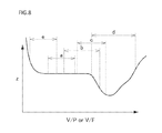
- a friction coefficient between two objects is fluctuated in accordance with a relative speed therebetween and a pressing force of each other. This relation is called a Stribeck curve.
- a friction coefficient z between the dresser 51 and the polishing pad 11 a fluctuates in accordance with a relative speed V and a pressing force F of the dresser 51 with respect to the polishing pad 11 a.
- FIG. 8 is a view schematically illustrating the Stribeck curve.
- a horizontal axis is a ratio V/F between the relative speed V and the pressing force F
- a vertical axis is a friction coefficient z.
- the friction coefficient z is almost constant regardless of the ratio V/F
- regions “b” to “e” in which the friction coefficient z fluctuates in accordance with the ratio V/F. If the dresser 51 operates in the region “a”, the friction coefficient z is constant even if the relative speed V fluctuates depending on a position of the dresser 51 .
- the controller 6 monitors a relation between the friction coefficient z and the ratio V/F, and the controller 6 adjusts the relative speed V and/or the pressing force F such that the dresser 51 operates in the region “a”. This relation is monitored as described below, and the controller 6 may display this relation on a display (not illustrated).
- the pressing force F(t) is obtained from the product of a pressure P supplied to the cylinder 532 from the electropneumatic regulator 531 and the area of the cylinder 532 (alternatively, from a load cell (not illustrated) provided on an axis between the dresser 51 and the cylinder 532 ).
- the pressing force F and the above pressure P are proportional. Therefore, instead of the pressing force F, the pressure P may be used in a state as described above.
- the rotation speed Ntt of the turntable 11 and the scanning cycle Tds of the dresser 51 can be controlled by the controller 6 , and therefore, the controller 6 can grasp them.
- a reciprocation distance L of the dresser 51 is known.
- the distance r(t) is detected by a detector of the scanning mechanism 56 .
- the friction coefficient z is a ratio f/F between the pressing force F and a force f for which the dresser 51 actually polishes the polishing pad 11 a .
- the polishing force f is almost equal to a horizontal direction force Fx acting on the polishing pad 11 a . Therefore, the friction coefficient z can be obtained by dividing the torque of the turntable 11 by dressing (difference between torque Tr of the turntable 11 and steady torque Tr 0 in the case where the dresser 51 does not contact to the polishing pad 11 a ) by the distance r.
- the torque Tr is obtained by multiplying a driving current I detected by a current detector 123 and torque constant Km[Nm/A] unique to the turntable motor 122 .
- the friction coefficient z can be monitored by obtaining the friction coefficient z, the relative speed V(t), and the pressing force F for each time t.
- the controller 6 can grasp which region in a Stribeck curve the dresser 51 is operating. Therefore, in the case where the dresser 51 operates in the regions “b” to “e”, the controller 6 can control the pressing force F (or a pressure P) and/or the relative speed V(t) such that the dresser 51 operates in the region “a”. As a result, a friction coefficient between the dresser 51 and the polishing pad 11 a becomes constant, and thus the polishing pad 11 a can be uniformly dressed.
- a controller 6 controls a turntable 11 and a dresser 51 under conditions set in any of the first to third embodiments. However, to prevent friction between the dresser 51 and the polishing pad 11 a , the controller 6 causes the turntable 11 and the dresser 51 to operate in a state in which the dresser 51 is disposed over the polishing pad 11 a without coming into contact thereto. This is called “air recipe”.
- the above condition is a condition obtained by calculation.
- the controller 6 causes the turntable 11 and the dresser 51 to operate by using the air recipe and regularly obtains the actual rotation speed Ntt of the turntable 11 , the actual scanning speed Vds of the dresser 51 , and the position r of the dresser 51 . Based on these values, the controller 6 calculates a locus of the dresser 51 on the polishing pad 11 a as illustrated in FIGS. 2A to 4C and 6A to 6B . This lotus may be displayed on a display.
- polishing pad 11 a It is determined based on this lotus whether the polishing pad 11 a is uniformly dressed. This determination may be performed by hand or by the controller 6 .
- the controller 6 causes the turntable 11 and the dresser 51 to operate by using the air recipe. Therefore, it is possible to confirm whether the polishing pad 11 a can be uniformly dressed when operating under the set condition without wearing the turntable 11 and the dresser 51 .
- a controller 6 according to a fifth embodiment performs self-control.
- the controller 6 according to the embodiment previously stores, in a database, a dressing condition in which a polishing pad 11 a is uniformly polished and a dressing condition in which the polishing pad 11 a is not uniformly dressed.
- the former condition is a condition, for example, which satisfies the above formulas (1) to (3) and in which a good result is obtained as a result of the confirmation described in the fourth embodiment.
- the latter condition is a condition, for example, which does not satisfy the above formulas (1) to (3) and in which a good result cannot be obtained as a result of the confirmation described in the fourth embodiment even if the formulas are satisfied.
- the dressing condition herein is, for example, a rotation cycle Ttt of the turntable 11 , a scanning cycle Tds of the dresser 51 , a scanning speed Vds of the dresser 51 , a pressing force F(t), and a pressure P(t), or a relation among them.
- FIG. 9 is a flowchart illustrating an example of a process operation of the controller 6 according to the fifth embodiment.
- the controller 6 receives a restriction condition for setting a dressing condition (step S 1 ).
- the restriction condition is, for example, a rotation speed Ntt of the turntable 11 and a machine constant of a polishing apparatus (such as a maximum scanning speed Vds of the dresser 51 ) in the case of performing serial processing.
- the controller 6 refers to a database and confirms whether there is a dressing condition which satisfies the restriction condition and in which the polishing pad 11 a can be uniformly dressed (step S 2 ).
- step S 2 If there is the condition (YES in step S 2 ), the controller 6 outputs the dressing condition (step S 3 ).
- step S 4 the controller 6 calculates a dressing condition by the method according to the above-described first to third embodiments. Then, the controller 6 refers to the database and confirms whether the calculated result and the dressing condition in which the polishing pad 11 a cannot be uniformly dressed are matched (step S 5 ). If matched (YES in step S 5 ), the controller 6 calculates another dressing condition (step S 4 ). If not, the confirmation described in the fourth embodiment is performed (step S 6 ).
- step S 4 Based on the obtained locus of the dresser 51 , in the case where it is determined that the polishing pad 11 a cannot be uniformly dressed (NO in step S 6 ), another dressing condition is calculated (step S 4 ).
- the controller 6 Based on the obtained locus of the dresser 51 , in the case where it is determined that the polishing pad 11 a can be uniformly dressed (YES in step S 6 ), the controller 6 adds the dressing condition calculated in step S 4 to the database (step S 7 ) and outputs the condition from the database (step S 3 ).
- step S 6 After confirmation by using the air recipe in step S 6 , it can be confirmed by further performing actual dressing whether the polishing pad 11 a can be uniformly dressed. Further, needless to say, the flowchart illustrated in FIG. 9 can be appropriately changed such as omitting a part of step.
- the controller 6 performs self-control. Therefore, a dressing condition capable of efficiently uniformly dressing the polishing pad 11 a can be obtained.
Landscapes
- Engineering & Computer Science (AREA)
- Mechanical Engineering (AREA)
- Finish Polishing, Edge Sharpening, And Grinding By Specific Grinding Devices (AREA)
- Grinding-Machine Dressing And Accessory Apparatuses (AREA)
- Mechanical Treatment Of Semiconductor (AREA)
Abstract
Description
Ttt/Tds≠an integer and Tds/Ttt≠an integer (1)
Tds/Ttt=n+1/N (2)
Tds/Ttt=n±d/2πr0 (3)
Vds=d/Ttt (4)
Vds=L/Tds (5)
Tds/Ttt=L/d (6)
Tds≤T0/m (7)
Tds=Ttt(n+d/2πr0)≈0.666(n+0.3188)≈3.54,4.21,4.87 [s] (n=5,6,7) (3′)
Tds=Ttt(n−d/2πr0)≈0.666(n−0.3188)≈3.12,3.78,4.45 [s] (n=5,6,7) (3″)
Vds=d/Ttt≈150 [mm/s] (4′)
Tds=L/Vds≈4.133 [s] (5′)
Tds(L−(Vds*total acceleration time/2))/Vds+total acceleration time=(620−(150*1.2)/2)/150+1.2=4.73 [s] (5″)
V(t)F(t)/r(t)=constant (7)
Claims (27)
Applications Claiming Priority (2)
| Application Number | Priority Date | Filing Date | Title |
|---|---|---|---|
| JP2015056922A JP6444785B2 (en) | 2015-03-19 | 2015-03-19 | Polishing apparatus, control method therefor, and dressing condition output method |
| JP2015-056922 | 2015-03-19 |
Publications (2)
| Publication Number | Publication Date |
|---|---|
| US20160271749A1 US20160271749A1 (en) | 2016-09-22 |
| US9962804B2 true US9962804B2 (en) | 2018-05-08 |
Family
ID=56923517
Family Applications (1)
| Application Number | Title | Priority Date | Filing Date |
|---|---|---|---|
| US15/071,091 Active 2036-08-10 US9962804B2 (en) | 2015-03-19 | 2016-03-15 | Polishing apparatus, method for controlling the same, and method for outputting a dressing condition |
Country Status (5)
| Country | Link |
|---|---|
| US (1) | US9962804B2 (en) |
| JP (2) | JP6444785B2 (en) |
| KR (2) | KR102292285B1 (en) |
| CN (1) | CN105983904B (en) |
| TW (2) | TWI704979B (en) |
Cited By (3)
| Publication number | Priority date | Publication date | Assignee | Title |
|---|---|---|---|---|
| US20180093363A1 (en) * | 2016-09-30 | 2018-04-05 | Ebara Corporation | Substrate polishing apparatus |
| US20180297170A1 (en) * | 2017-04-18 | 2018-10-18 | Taiwan Semiconductor Manufacturing Company, Ltd. | Apparatus and method for cmp pad conditioning |
| US10828747B2 (en) * | 2017-07-05 | 2020-11-10 | Ebara Corporation | Substrate polishing apparatus and method |
Families Citing this family (10)
| Publication number | Priority date | Publication date | Assignee | Title |
|---|---|---|---|---|
| JP6307428B2 (en) * | 2014-12-26 | 2018-04-04 | 株式会社荏原製作所 | Polishing apparatus and control method thereof |
| US10576606B2 (en) * | 2017-06-19 | 2020-03-03 | Taiwan Semiconductor Manufacturing Company, Ltd. | Platen rotation system and method |
| JP7269074B2 (en) * | 2018-04-26 | 2023-05-08 | 株式会社荏原製作所 | Polishing device and polishing system equipped with polishing pad surface texture measuring device |
| US12208487B2 (en) | 2018-10-29 | 2025-01-28 | Taiwan Semiconductor Manufacturing Co., Ltd. | Chemical mechanical polishing apparatus and method |
| TWI819138B (en) | 2018-12-21 | 2023-10-21 | 日商荏原製作所股份有限公司 | Grinding device and dressing method of grinding components |
| CN111421462B (en) * | 2019-01-08 | 2022-03-22 | 中芯国际集成电路制造(上海)有限公司 | chemical mechanical polishing method |
| US11794305B2 (en) | 2020-09-28 | 2023-10-24 | Applied Materials, Inc. | Platen surface modification and high-performance pad conditioning to improve CMP performance |
| CN112775838A (en) * | 2021-01-04 | 2021-05-11 | 长江存储科技有限责任公司 | Grinding pad trimmer and chemical mechanical grinding equipment comprising same |
| TWI813332B (en) * | 2022-06-10 | 2023-08-21 | 中國砂輪企業股份有限公司 | Chemical-mechanical polishing pad conditioner and preparation method thereof |
| CN121361023B (en) * | 2025-11-14 | 2026-04-28 | 上海矽加半导体有限公司 | Control methods, devices, equipment, media and products for CMP equipment |
Citations (10)
| Publication number | Priority date | Publication date | Assignee | Title |
|---|---|---|---|---|
| JPH09300207A (en) | 1996-05-21 | 1997-11-25 | Toshiba Mach Co Ltd | Abrasive cloth dressing method and device thereof |
| US20040242122A1 (en) * | 2003-05-28 | 2004-12-02 | Jens Kramer | Method and system for controlling the chemical mechanical polishing by using a sensor signal of a pad conditioner |
| US20080070479A1 (en) * | 2004-11-01 | 2008-03-20 | Ebara Corporation | Polishing Apparatus |
| US20080146119A1 (en) * | 2005-01-21 | 2008-06-19 | Tatsuya Sasaki | Substrate Polishing Method and Apparatus |
| US20100081361A1 (en) | 2008-09-26 | 2010-04-01 | Akira Fukuda | Dressing method, method of determining dressing conditions, program for determining dressing conditions, and polishing apparatus |
| US20110159783A1 (en) * | 2008-08-21 | 2011-06-30 | Makoto Fukushima | Method and apparatus for polishing a substrate |
| US20130122783A1 (en) * | 2010-04-30 | 2013-05-16 | Applied Materials, Inc | Pad conditioning force modeling to achieve constant removal rate |
| US9108292B2 (en) * | 2013-02-22 | 2015-08-18 | Ebara Corporation | Method of obtaining a sliding distance distribution of a dresser on a polishing member, method of obtaining a sliding vector distribution of a dresser on a polishing member, and polishing apparatus |
| US9156130B2 (en) * | 2013-02-25 | 2015-10-13 | Ebara Corporation | Method of adjusting profile of a polishing member used in a polishing apparatus, and polishing apparatus |
| US9469013B2 (en) * | 2011-06-08 | 2016-10-18 | Ebara Corporation | Method and apparatus for conditioning a polishing pad |
Family Cites Families (14)
| Publication number | Priority date | Publication date | Assignee | Title |
|---|---|---|---|---|
| JP2851839B1 (en) * | 1997-07-02 | 1999-01-27 | 松下電子工業株式会社 | Wafer polishing method and polishing pad dressing method |
| JP3788035B2 (en) * | 1998-06-15 | 2006-06-21 | 松下電器産業株式会社 | Polishing cloth dressing method |
| US6623334B1 (en) * | 1999-05-05 | 2003-09-23 | Applied Materials, Inc. | Chemical mechanical polishing with friction-based control |
| JP2001269861A (en) * | 2000-03-23 | 2001-10-02 | Sony Corp | Polishing method, polishing apparatus, processing amount calculation method in polishing processing, and processing amount calculation apparatus |
| JP2004047876A (en) * | 2002-07-15 | 2004-02-12 | Tokyo Seimitsu Co Ltd | Polishing apparatus and polishing method |
| JP4817687B2 (en) * | 2005-03-18 | 2011-11-16 | 株式会社荏原製作所 | Polishing equipment |
| US20060276111A1 (en) * | 2005-06-02 | 2006-12-07 | Applied Materials, Inc. | Conditioning element for electrochemical mechanical processing |
| JP4768335B2 (en) * | 2005-06-30 | 2011-09-07 | 株式会社東芝 | Chemical mechanical polishing method of organic film, semiconductor device manufacturing method, and program |
| JP5257752B2 (en) * | 2008-04-08 | 2013-08-07 | 株式会社ニコン | Polishing pad dressing method |
| US8096852B2 (en) * | 2008-08-07 | 2012-01-17 | Applied Materials, Inc. | In-situ performance prediction of pad conditioning disk by closed loop torque monitoring |
| CN102689266A (en) * | 2011-03-23 | 2012-09-26 | 中芯国际集成电路制造(上海)有限公司 | Polishing device and wafer polishing method |
| JP5741497B2 (en) * | 2012-02-15 | 2015-07-01 | 信越半導体株式会社 | Wafer double-side polishing method |
| JP5927083B2 (en) * | 2012-08-28 | 2016-05-25 | 株式会社荏原製作所 | Dressing process monitoring method and polishing apparatus |
| JP6372859B2 (en) * | 2015-10-01 | 2018-08-15 | 信越半導体株式会社 | Polishing pad conditioning method and polishing apparatus |
-
2015
- 2015-03-19 JP JP2015056922A patent/JP6444785B2/en active Active
-
2016
- 2016-01-29 TW TW108130946A patent/TWI704979B/en active
- 2016-01-29 TW TW105102816A patent/TWI681842B/en active
- 2016-03-15 US US15/071,091 patent/US9962804B2/en active Active
- 2016-03-16 KR KR1020160031253A patent/KR102292285B1/en active Active
- 2016-03-18 CN CN201610156885.3A patent/CN105983904B/en active Active
-
2018
- 2018-11-28 JP JP2018221925A patent/JP6625720B2/en active Active
-
2021
- 2021-08-13 KR KR1020210107062A patent/KR102455815B1/en active Active
Patent Citations (11)
| Publication number | Priority date | Publication date | Assignee | Title |
|---|---|---|---|---|
| JPH09300207A (en) | 1996-05-21 | 1997-11-25 | Toshiba Mach Co Ltd | Abrasive cloth dressing method and device thereof |
| US20040242122A1 (en) * | 2003-05-28 | 2004-12-02 | Jens Kramer | Method and system for controlling the chemical mechanical polishing by using a sensor signal of a pad conditioner |
| US20080070479A1 (en) * | 2004-11-01 | 2008-03-20 | Ebara Corporation | Polishing Apparatus |
| US20080146119A1 (en) * | 2005-01-21 | 2008-06-19 | Tatsuya Sasaki | Substrate Polishing Method and Apparatus |
| US20110159783A1 (en) * | 2008-08-21 | 2011-06-30 | Makoto Fukushima | Method and apparatus for polishing a substrate |
| US20100081361A1 (en) | 2008-09-26 | 2010-04-01 | Akira Fukuda | Dressing method, method of determining dressing conditions, program for determining dressing conditions, and polishing apparatus |
| JP2010076049A (en) | 2008-09-26 | 2010-04-08 | Ebara Corp | Dressing method, method for determining dressing condition, program for determining dressing condition, and polishing device |
| US20130122783A1 (en) * | 2010-04-30 | 2013-05-16 | Applied Materials, Inc | Pad conditioning force modeling to achieve constant removal rate |
| US9469013B2 (en) * | 2011-06-08 | 2016-10-18 | Ebara Corporation | Method and apparatus for conditioning a polishing pad |
| US9108292B2 (en) * | 2013-02-22 | 2015-08-18 | Ebara Corporation | Method of obtaining a sliding distance distribution of a dresser on a polishing member, method of obtaining a sliding vector distribution of a dresser on a polishing member, and polishing apparatus |
| US9156130B2 (en) * | 2013-02-25 | 2015-10-13 | Ebara Corporation | Method of adjusting profile of a polishing member used in a polishing apparatus, and polishing apparatus |
Cited By (6)
| Publication number | Priority date | Publication date | Assignee | Title |
|---|---|---|---|---|
| US20180093363A1 (en) * | 2016-09-30 | 2018-04-05 | Ebara Corporation | Substrate polishing apparatus |
| US10625395B2 (en) * | 2016-09-30 | 2020-04-21 | Ebara Corporation | Substrate polishing apparatus |
| US20180297170A1 (en) * | 2017-04-18 | 2018-10-18 | Taiwan Semiconductor Manufacturing Company, Ltd. | Apparatus and method for cmp pad conditioning |
| US10675732B2 (en) * | 2017-04-18 | 2020-06-09 | Taiwan Semiconductor Manufacturing Company, Ltd. | Apparatus and method for CMP pad conditioning |
| US11679472B2 (en) | 2017-04-18 | 2023-06-20 | Taiwan Semiconductor Manufacturing Company, Ltd. | Method for CMP pad conditioning |
| US10828747B2 (en) * | 2017-07-05 | 2020-11-10 | Ebara Corporation | Substrate polishing apparatus and method |
Also Published As
| Publication number | Publication date |
|---|---|
| CN105983904A (en) | 2016-10-05 |
| TWI681842B (en) | 2020-01-11 |
| KR102292285B1 (en) | 2021-08-24 |
| US20160271749A1 (en) | 2016-09-22 |
| KR20210105857A (en) | 2021-08-27 |
| TW201637778A (en) | 2016-11-01 |
| JP6444785B2 (en) | 2018-12-26 |
| KR20160112992A (en) | 2016-09-28 |
| KR102455815B1 (en) | 2022-10-18 |
| JP2016175146A (en) | 2016-10-06 |
| JP6625720B2 (en) | 2019-12-25 |
| JP2019059017A (en) | 2019-04-18 |
| TWI704979B (en) | 2020-09-21 |
| TW202005748A (en) | 2020-02-01 |
| CN105983904B (en) | 2018-11-02 |
Similar Documents
| Publication | Publication Date | Title |
|---|---|---|
| US9962804B2 (en) | Polishing apparatus, method for controlling the same, and method for outputting a dressing condition | |
| JP5964262B2 (en) | Method for adjusting profile of polishing member used in polishing apparatus, and polishing apparatus | |
| JP2968784B1 (en) | Polishing method and apparatus used therefor | |
| US10016871B2 (en) | Polishing apparatus and controlling the same | |
| US9108292B2 (en) | Method of obtaining a sliding distance distribution of a dresser on a polishing member, method of obtaining a sliding vector distribution of a dresser on a polishing member, and polishing apparatus | |
| US9017138B2 (en) | Retaining ring monitoring and control of pressure | |
| EP3812094B1 (en) | Polishing method and polishing apparatus | |
| US10335918B2 (en) | Workpiece processing apparatus | |
| CN114683161B (en) | Polishing apparatus and polishing method | |
| JP2008141186A (en) | Polishing method and polishing apparatus | |
| JP6394569B2 (en) | Wafer polishing method and polishing apparatus | |
| US6913525B2 (en) | CMP device and production method for semiconductor device | |
| JP2019147233A (en) | Processing device and processing method | |
| JP2006062055A (en) | Processing method, processing device, and rectangular flat plate processed product processed by this processing method | |
| US20250178158A1 (en) | Substrate polishing method and substrate polishing apparatus | |
| JP5120696B2 (en) | Polishing equipment | |
| JP2003022992A (en) | Semiconductor manufacturing apparatus and semiconductor manufacturing method |
Legal Events
| Date | Code | Title | Description |
|---|---|---|---|
| AS | Assignment |
Owner name: EBARA CORPORATION, JAPAN Free format text: ASSIGNMENT OF ASSIGNORS INTEREST;ASSIGNOR:SHINOZAKI, HIROYUKI;REEL/FRAME:038017/0450 Effective date: 20160311 |
|
| STCF | Information on status: patent grant |
Free format text: PATENTED CASE |
|
| MAFP | Maintenance fee payment |
Free format text: PAYMENT OF MAINTENANCE FEE, 4TH YEAR, LARGE ENTITY (ORIGINAL EVENT CODE: M1551); ENTITY STATUS OF PATENT OWNER: LARGE ENTITY Year of fee payment: 4 |
|
| MAFP | Maintenance fee payment |
Free format text: PAYMENT OF MAINTENANCE FEE, 8TH YEAR, LARGE ENTITY (ORIGINAL EVENT CODE: M1552); ENTITY STATUS OF PATENT OWNER: LARGE ENTITY Year of fee payment: 8 |