US996167A - Flexible stay-bolt. - Google Patents
Flexible stay-bolt. Download PDFInfo
- Publication number
- US996167A US996167A US47163109A US1909471631A US996167A US 996167 A US996167 A US 996167A US 47163109 A US47163109 A US 47163109A US 1909471631 A US1909471631 A US 1909471631A US 996167 A US996167 A US 996167A
- Authority
- US
- United States
- Prior art keywords
- bolt
- stay
- strands
- head
- heads
- Prior art date
- Legal status (The legal status is an assumption and is not a legal conclusion. Google has not performed a legal analysis and makes no representation as to the accuracy of the status listed.)
- Expired - Lifetime
Links
- 238000003466 welding Methods 0.000 description 6
- 239000002184 metal Substances 0.000 description 5
- 239000007787 solid Substances 0.000 description 4
- 238000010276 construction Methods 0.000 description 2
- XLYOFNOQVPJJNP-UHFFFAOYSA-N water Substances O XLYOFNOQVPJJNP-UHFFFAOYSA-N 0.000 description 2
- 238000005452 bending Methods 0.000 description 1
- 230000008602 contraction Effects 0.000 description 1
- 238000005336 cracking Methods 0.000 description 1
- 238000005553 drilling Methods 0.000 description 1
- 238000000034 method Methods 0.000 description 1
- QCOXCILKVHKOGO-UHFFFAOYSA-N n-(2-nitramidoethyl)nitramide Chemical compound [O-][N+](=O)NCCN[N+]([O-])=O QCOXCILKVHKOGO-UHFFFAOYSA-N 0.000 description 1
Images
Classifications
-
- F—MECHANICAL ENGINEERING; LIGHTING; HEATING; WEAPONS; BLASTING
- F22—STEAM GENERATION
- F22B—METHODS OF STEAM GENERATION; STEAM BOILERS
- F22B7/00—Steam boilers of furnace-tube type, i.e. the combustion of fuel being performed inside one or more furnace tubes built-in in the boiler body
- F22B7/16—Component parts thereof; Accessories therefor, e.g. stay-bolt connections
Definitions
- One object of my invention is to stay the inside and outside plates of the water-space of the fire-box of a boiler with a flexible stay-bolt that does not necessitate the drilling of a larger hole in the outside sheet or plate of the boiler, than is permissible in common practice, when the ordinary, so called, non-flexible, stay-bolt is used.
- Another object of the invention is to stay the inside and outside sheets or plates of the water-space of the fire-box of a boiler with a flexible stay-bolt of predetermined flexibility, said flexibility extending, substantially, the tot-a1 width of the water-space from the inner to the outer plates, thereby avoiding the breakage of the stay-bolt due to the expansion and contraction of the boiler plates when the boiler is in service.
- Another object of the invention is to stay the inside and outside plates of the boiler with a flexible stay-bolt, so designed and constructed that when the axis of the hole in the inner plate and the axis of the hole in the outer plate, by means of which'the stay-bolt is secured to the plates, are de flected from a straight line, the bending strain in the plates due to the strain in the stay-bolt, resulting from said deflection of the plates, will be reduced to such an extent as to avoid the cracking of the plates.
- the invention also contemplates a flexible stay-bolt for the staying of the inner and outer plates of a boiler, which can be easily applied, readily examined and tested for breakage, and can have a tell-tale hole if extreme precautions are desired.
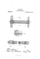
- FIG. 1 is the stay-bolt after being applied to the boiler.
- Fig. 2 is a portion of Fig. 3, which is the section of the outside head G of the stay-bolt, along axis F-E,
- Fig. 3 is the section of the outer head G of the stay-bolt, taken through the axis F-E.
- Fig. 4 is the cross-section of the stay-bolt, taken through the line AB, and at right angle to the axis F-E.
- Fig. 5 is the section of the inner head G of the stay-bolt, along the axis F-E.
- C represents the outer boiler plate
- D the inner boiler plate of the water space of the fire-box of the boiler
- G the outer head of the stay-bolt
- G the inner head, with threads cut to engage in similar threads at their respective ends in the inner and outer plates of the boiler.
- the pitch of the threads on the heads are similar on both ends, but the outer thread is of suflicient diameter to permit the application of the stay-bolt without the inner head G having its threads engage with the thread in the outer boiler plate G.
- the thread on the outer head G is cut the total length of that head, but the inner head G has the threads out only a part of its length,
- the flexible portion of the stay-bolt is between the heads G and G and is shown in the preferred form consisting of a plurality of rods or strands, so designed and con Structed as to form a stay-bolt of compact section of the desired diameter.
- Fig. 4 shows the cross-section of the flexible portion of the stay-bolt, consisting of a core rod 0; an inner layer consisting of eight (8) strand-s, surrounding the core rod; and an outer layer, consisting of twelve (12) strands, surrounding the inner layer of strands.
- the strands, as shown, lie lengthwise of the staybolt, parallel to one another and with the core rod, and merge into the heads G and G at their respective ends.
- the points of junction of the various strands and core rod, with the head, at each end, are contained in a plane perpendicular to the axis of the stay-bolt.
- the imaginary planes are represented by c and 6 at which points the strands a, m, 111, 01, and the core rod 0 are shown merging into the corresponding heads G, and G
- that portion of the strands and core which is between the heads or planes 6 and e are shaped so that when assembled in their respective positions, the adjacent surfaces of the strands and core are in close contact thereby giving a crosssection of practically solid metal of the desired diameter.
- each surface 1s given its required welding stock, so that when the strands and core are assembled preparatory to welding, those portions of the strands and core between the heads or planes 6 and e are not in contact with one another but stand apart.
- the enlarged portion of the strands and core will form a solid head without welding the portion between the heads.
- the heads G and G are designed and constructed, in the preferred form, with a sleeve or collar, 6 and b respectively, projecting from their inner end or edge, toward the water side of the bolt, the exterior diameter of the sleeve being the same size as the diameter of the head.
- the sleeve 5 is shown enlarged in Fig. 2, in order to describe its construction.
- the inner surface of the sleeve or collar has a flaring mouth, as at a, the section of which has the contour of a circle; and receding toward its base, at which point it terminates in the head G in the same plane as the junction of the strands with the head.
- the inner surface, at its base, is in close contact with the strands, thereby protecting the strands at their junction with the head, while the flaring mouth allows the strands to bend around the inner surface at that point.
- the thread on the outer head extends the total length of the head, but the thread on the inner head does not extend the full length of the head but stops at a suflicient distance from the sleeve 6 to secure the necessary amount of metal to support the sleeve.
- the outer head G is provided with a square lug cl, by means of which the stay-bolt is applied with a square wrench.
- the sect-ion of the flexible portion of the stay-bolt to be composed of a core rod, an inner layer consisting of eight strands, and an outer layer of twelve strands, all lying parallel to one another and to the axis of the stay-bolt; it is conceivable this arrangement might be advantageously replaced by a different arrangement of the strands, in regard to the number, shape, and method of assembling them around the axis, in order to secure a While the telltale hole is shown in the drawings in the outer head only, yet it is conceivable that it might bev advantageous to also have the tell-tale hole in the inner head of the stay-bolt.
- a flexible stay-bolt comprising a bodyportion consisting of a plurality of strands or rods assembled in close contact with relatively-conforming intervening faces and collectively forming a body of metal of virtually solid cross-section.
- a flexible staybolt comprising a bodyportion consisting of a plurality of strands or rods assembled in close contact with relativelyconforming intervening faces and collectively forming a body of metal of virtually solid cross-section, and threaded heads constituted by the welded terminal end-portions of the assembled set of sa1d body strands or rods.
- a flexible stay-bolt consisting of a plurality of assembled strands or rods termlnating in integral threaded heads and having an integral collar projectlng from sa1d heads over and beyond the junction of the relatively-free portions of the set of sa1d strands or rods with said terminal heads.”
- a flexible stay-bolt consisting of a plurality of assembled strands or rods terminating in integral threaded heads and having a collar projecting from sa1d heads over and beyond the junction of the relativelyfree portions of the set of sa1d strands or rods with said terminal heads, said collar having an inner flaring mouth the base of which intersects said junction of the relatively-free portions of said strands or rod with the terminal head.
- a flexible stay-bolt consisting of a plurality of strands 0r rods constituting a rods and entering one of said strands or body-portion formed by the assembled rods at the relatively-free portion thereof. 10 strands or rods and threaded heads formed In testimony whereof I affix my signature by the Welded terminal end-portions of the asin the presence of two witnesseses.
Landscapes
- Engineering & Computer Science (AREA)
- Chemical & Material Sciences (AREA)
- Combustion & Propulsion (AREA)
- Physics & Mathematics (AREA)
- Thermal Sciences (AREA)
- Mechanical Engineering (AREA)
- General Engineering & Computer Science (AREA)
- Wire Processing (AREA)
Description
H, W, UHL. FLEXIBLE STAY BOLT. APPLICATION FILED JAI I. 11,'1909.
Patented June 27, 1911.
HENRY W; UHL, OF PORTSMOUTH, OHIO.
FLEXIBLE STAY-BOLT.
Specification of Letters Patent.
Application filed January 11, 1909.
Patented June 27, 1911.
Serial No. 471,631.
To all whom it may concern:
Be it known that I, HENRY W. UHL, a citizen of the United States, residing at Portsmouth, in the county of Scioto and State of Ohio, have invented new and useful Improvements in Flexible Stay-Bolts, of which the following is a specification.
One object of my invention is to stay the inside and outside plates of the water-space of the fire-box of a boiler with a flexible stay-bolt that does not necessitate the drilling of a larger hole in the outside sheet or plate of the boiler, than is permissible in common practice, when the ordinary, so called, non-flexible, stay-bolt is used.
Another object of the invention is to stay the inside and outside sheets or plates of the water-space of the fire-box of a boiler with a flexible stay-bolt of predetermined flexibility, said flexibility extending, substantially, the tot-a1 width of the water-space from the inner to the outer plates, thereby avoiding the breakage of the stay-bolt due to the expansion and contraction of the boiler plates when the boiler is in service.
Another object of the invention is to stay the inside and outside plates of the boiler with a flexible stay-bolt, so designed and constructed that when the axis of the hole in the inner plate and the axis of the hole in the outer plate, by means of which'the stay-bolt is secured to the plates, are de flected from a straight line, the bending strain in the plates due to the strain in the stay-bolt, resulting from said deflection of the plates, will be reduced to such an extent as to avoid the cracking of the plates.
The invention also contemplates a flexible stay-bolt for the staying of the inner and outer plates of a boiler, which can be easily applied, readily examined and tested for breakage, and can have a tell-tale hole if extreme precautions are desired.
These objects I attain as hereinafter set forth, reference being had to the accompanying drawings, in which Figure 1 is the stay-bolt after being applied to the boiler. Fig. 2, is a portion of Fig. 3, which is the section of the outside head G of the stay-bolt, along axis F-E,
and enlarged to show the construction of the sleeve or collar Z) of the head. Fig. 3, is the section of the outer head G of the stay-bolt, taken through the axis F-E. Fig. 4, is the cross-section of the stay-bolt, taken through the line AB, and at right angle to the axis F-E. Fig. 5, is the section of the inner head G of the stay-bolt, along the axis F-E.
In the above drawings, C represents the outer boiler plate, and D the inner boiler plate of the water space of the fire-box of the boiler; G the outer head of the stay-bolt, and G the inner head, with threads cut to engage in similar threads at their respective ends in the inner and outer plates of the boiler. The pitch of the threads on the heads are similar on both ends, but the outer thread is of suflicient diameter to permit the application of the stay-bolt without the inner head G having its threads engage with the thread in the outer boiler plate G. The thread on the outer head G is cut the total length of that head, but the inner head G has the threads out only a part of its length,
for reasons which will be referred to later.
The flexible portion of the stay-bolt is between the heads G and G and is shown in the preferred form consisting of a plurality of rods or strands, so designed and con Structed as to form a stay-bolt of compact section of the desired diameter. Fig. 4 shows the cross-section of the flexible portion of the stay-bolt, consisting of a core rod 0; an inner layer consisting of eight (8) strand-s, surrounding the core rod; and an outer layer, consisting of twelve (12) strands, surrounding the inner layer of strands. The strands, as shown, lie lengthwise of the staybolt, parallel to one another and with the core rod, and merge into the heads G and G at their respective ends. The points of junction of the various strands and core rod, with the head, at each end, are contained in a plane perpendicular to the axis of the stay-bolt. In the drawing, the imaginary planes are represented by c and 6 at which points the strands a, m, 111, 01, and the core rod 0 are shown merging into the corresponding heads G, and G To construct such a bolt, that portion of the strands and core which is between the heads or planes 6 and e are shaped so that when assembled in their respective positions, the adjacent surfaces of the strands and core are in close contact thereby giving a crosssection of practically solid metal of the desired diameter. As the heads are formed by welding the adjacent surfaces of the strands together, I enlarge that portion of the strands and core outside of the planes 0 and 6 in order to furnish the necessary metal for Welding. In enlarging this portion of the strands and core, each surface 1s given its required welding stock, so that when the strands and core are assembled preparatory to welding, those portions of the strands and core between the heads or planes 6 and e are not in contact with one another but stand apart. By securing a welding heat on the heads, the enlarged portion of the strands and core will form a solid head without welding the portion between the heads.
The heads G and G are designed and constructed, in the preferred form, with a sleeve or collar, 6 and b respectively, projecting from their inner end or edge, toward the water side of the bolt, the exterior diameter of the sleeve being the same size as the diameter of the head. The sleeve 5 is shown enlarged in Fig. 2, in order to describe its construction. The inner surface of the sleeve or collar has a flaring mouth, as at a, the section of which has the contour of a circle; and receding toward its base, at which point it terminates in the head G in the same plane as the junction of the strands with the head. The inner surface, at its base, is in close contact with the strands, thereby protecting the strands at their junction with the head, while the flaring mouth allows the strands to bend around the inner surface at that point. The thread on the outer head extends the total length of the head, but the thread on the inner head does not extend the full length of the head but stops at a suflicient distance from the sleeve 6 to secure the necessary amount of metal to support the sleeve. The outer head G is provided with a square lug cl, by means of which the stay-bolt is applied with a square wrench.
While I have shown the sect-ion of the flexible portion of the stay-bolt to be composed of a core rod, an inner layer consisting of eight strands, and an outer layer of twelve strands, all lying parallel to one another and to the axis of the stay-bolt; it is conceivable this arrangement might be advantageously replaced by a different arrangement of the strands, in regard to the number, shape, and method of assembling them around the axis, in order to secure a While the telltale hole is shown in the drawings in the outer head only, yet it is conceivable that it might bev advantageous to also have the tell-tale hole in the inner head of the stay-bolt.
Although I have shown the heads G and G having a sleeve e and 6 respectively, to protect the strands where they terminate into the heads, when the stay-bolt is subject to extreme severe conditions; yet it is conceivable that the sleeves e and e might be advantageously omitted on stay-bolts which are subject to a less severe strain, as the head G would have its thread cut its entire length and the outer head G would be the same size as the inner head G I claim:
1. A flexible stay-bolt, comprising a bodyportion consisting of a plurality of strands or rods assembled in close contact with relatively-conforming intervening faces and collectively forming a body of metal of virtually solid cross-section.
2. A flexible staybolt, comprising a bodyportion consisting of a plurality of strands or rods assembled in close contact with relativelyconforming intervening faces and collectively forming a body of metal of virtually solid cross-section, and threaded heads constituted by the welded terminal end-portions of the assembled set of sa1d body strands or rods.
3. A flexible stay-bolt consisting of a plurality of assembled strands or rods termlnating in integral threaded heads and having an integral collar projectlng from sa1d heads over and beyond the junction of the relatively-free portions of the set of sa1d strands or rods with said terminal heads."
4;. A flexible stay-bolt consisting of a plurality of assembled strands or rods terminating in integral threaded heads and having a collar projecting from sa1d heads over and beyond the junction of the relativelyfree portions of the set of sa1d strands or rods with said terminal heads, said collar having an inner flaring mouth the base of which intersects said junction of the relatively-free portions of said strands or rod with the terminal head. q
5. A flexible stay-bolt consisting of a plurality of strands 0r rods constituting a rods and entering one of said strands or body-portion formed by the assembled rods at the relatively-free portion thereof. 10 strands or rods and threaded heads formed In testimony whereof I affix my signature by the Welded terminal end-portions of the asin the presence of two Witnesses.
sembied set of said strands or rods, and hav- HENRY W. UHL. ing a hole or channel extending through the Witnesses: head formed by the Welded terminal end- JAMES P. PURDUM,
portions of the assembled set of strands or EDNA MAE DISTELRATH.
Copies of this patent may be obtained for five cents each, by addressing the Commissioner of Patents, Washington, D. G.
Priority Applications (1)
| Application Number | Priority Date | Filing Date | Title |
|---|---|---|---|
| US47163109A US996167A (en) | 1909-01-11 | 1909-01-11 | Flexible stay-bolt. |
Applications Claiming Priority (1)
| Application Number | Priority Date | Filing Date | Title |
|---|---|---|---|
| US47163109A US996167A (en) | 1909-01-11 | 1909-01-11 | Flexible stay-bolt. |
Publications (1)
| Publication Number | Publication Date |
|---|---|
| US996167A true US996167A (en) | 1911-06-27 |
Family
ID=3064499
Family Applications (1)
| Application Number | Title | Priority Date | Filing Date |
|---|---|---|---|
| US47163109A Expired - Lifetime US996167A (en) | 1909-01-11 | 1909-01-11 | Flexible stay-bolt. |
Country Status (1)
| Country | Link |
|---|---|
| US (1) | US996167A (en) |
-
1909
- 1909-01-11 US US47163109A patent/US996167A/en not_active Expired - Lifetime
Similar Documents
| Publication | Publication Date | Title |
|---|---|---|
| US1025706A (en) | Stay-bolt construction for steam-boilers. | |
| US1229909A (en) | Stay-bolt for boilers. | |
| US1884481A (en) | Superheater header | |
| US804590A (en) | Boiler-tube fastener. | |
| US1077051A (en) | Stay-bolt. | |
| US885123A (en) | Steam-boiler. | |
| US377001A (en) | new yoek | |
| US1250979A (en) | Boiler. | |
| US1117251A (en) | Pipe-fitting. | |
| US1236224A (en) | Stay-bolt for boilers. | |
| US1359587A (en) | Staybolt structure for steam-boilers | |
| US761719A (en) | Steam-generator. | |
| US1168728A (en) | Flexible stay-bolt. | |
| US1154194A (en) | Header. | |
| US159992A (en) | Improvement in joints for steam-generators | |
| US770651A (en) | Boiler stay-bolt | |
| US1146482A (en) | Stay-bolt. | |
| US96190A (en) | Improvement in steam-generators | |
| US757973A (en) | Stay-bolt. | |
| US1229910A (en) | Stay-bolt for boilers. | |
| US423792A (en) | Jonathan gresty | |
| US1154469A (en) | Stay-bolt. | |
| US415976A (en) | Sectional steam-boiler | |
| US537935A (en) | Sectional steam-boiler | |
| US779136A (en) | Boiler tube-sheet. |