US995336A - Folding bed. - Google Patents
Folding bed. Download PDFInfo
- Publication number
- US995336A US995336A US1910579624A US995336A US 995336 A US995336 A US 995336A US 1910579624 A US1910579624 A US 1910579624A US 995336 A US995336 A US 995336A
- Authority
- US
- United States
- Prior art keywords
- bed
- posts
- vertical
- guideway
- pivoted
- Prior art date
- Legal status (The legal status is an assumption and is not a legal conclusion. Google has not performed a legal analysis and makes no representation as to the accuracy of the status listed.)
- Expired - Lifetime
Links
- 230000008093 supporting effect Effects 0.000 description 6
- 238000010276 construction Methods 0.000 description 3
- 230000006872 improvement Effects 0.000 description 2
- 238000005192 partition Methods 0.000 description 2
Images


Classifications
-
- A—HUMAN NECESSITIES
- A47—FURNITURE; DOMESTIC ARTICLES OR APPLIANCES; COFFEE MILLS; SPICE MILLS; SUCTION CLEANERS IN GENERAL
- A47C—CHAIRS; SOFAS; BEDS
- A47C17/00—Sofas; Couches; Beds
- A47C17/38—Wall beds
- A47C17/40—Wall beds having balancing members, e.g. weights, springs
-
- A—HUMAN NECESSITIES
- A47—FURNITURE; DOMESTIC ARTICLES OR APPLIANCES; COFFEE MILLS; SPICE MILLS; SUCTION CLEANERS IN GENERAL
- A47C—CHAIRS; SOFAS; BEDS
- A47C17/00—Sofas; Couches; Beds
- A47C17/52—Cabinet beds; Table beds, or like beds; Wardrobe beds
Definitions
- Mr lam A T TORNE Y 1n NORRIS PETERS ca, WASHINGTGN, :14 c.
- WITNESSES IN VEN TOR 1%, Nan/1 7 22% MW .jn; W ATTORNEY K. EVANS.
- the present invention relates to improve ments in folding beds, and particularly to beds adapted to be received within a closet or other compartment when not in use.
- the object of the invention being to provide a folding bed of great simplicity of construction, one which, being composed of few parts and those of simple construction will not readily get out of order, which will be safe and durable in use, and especially which will require very little effort to open or close the bed.
- a further object is to provide an improved construction of folding bed which will adapt itself to various styles of closets or cabinets for the purpose of concealing the same when not in use.
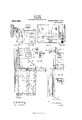
- Figure 1 is a vertical section of the bed, closed; Fig. 2 is a broken similar View of the bed in an intermediate position; Fig. 3 is a vertical section of the bed fully extended for use; Fig. 4 is an enlarged detail side view of the main portion of the supporting frame; Fig. 5 is a front view of the same; Fig. 6 is a detail horizontal section on the line 66 of Fig. 5; Fig. 7 is an enlarged side view of the movable fulcrum on which the bed turns; Fig. 8 is a cross section on the line 88 of Fig. 7 Fig.
- FIG. 9 is an enlarged detail vertical section of the upper end of a support for bed, and of the guideway for moving the support laterally into a closet or other compartment;
- Fig. 10 is a front View of the same;
- Fig. 11 is a rear detail View of a roller upon which the support travels when so moving laterally;
- Fig. 12 is a side view of the same;
- Fig. 13 is a front view of the bed, in its closed position, showing in section a partition of a closet (shown in dotted lines) into which the bed can be moved when not in use;
- Fig. 14 is a vertical section, showing the guides for moving said bed in said closet.
- 1 indicates a cabinet, to the rear wall 2 of which are secured brackets 3, by which are secured vertical angle bars 4 forming guideways for the bed frame proper. From the lower ends Specification of Letters Patent.
- angle bars project horizontal arms 5, the outer ends of which are connected to said guideways by oblique braces 6.
- To said arms are pivoted two pairs of equal and parallel posts 7, to the upper ends of which are pivoted horizontal supports 8.
- FIG. 9 indicates side pieces of the bed frame, connected at the bottom of the bed by a transverse bar 10, and sup-porting at said bottom the foot board 11.
- the side pieces 9 are connected at the head of the bed by an angle bar 14, best shown in Figs. 4 and 5, and to the bed frame thus formed is secured a fixed head board 15.
- brackets 16 Secured to the front side of said head board at its ends, and also to the said side pieces, are brackets 16, which are braced by oblique braces 17 secured at their lower ends to the side pieces.
- To the upper ends of said brackets are pivoted, as shown at 19, the side arms 20 of the head rail 21, from which side arms extend laterally forked guide pieces 22 which engage the edges of said bars at.
- pivot plates 25 To the side pieces are bolted, as shown at 24, pivot plates 25, the upper portions 26 of which extend outwardly or laterally.
- said upper portions In said upper portions are screwed two pins 27, 28, arranged obliquely with reference to said side plates, the stems of which pins engage notches 29 in 'the upper edges of the supports 8.
- each pivot pin 27 engages one of said notches in the closed position, and each pin 28 engages another notch in its open-position, so that, on each side of the bed, only two notches are in use throughout the complete operation of opening or closing the bed.
- each side there are provided, on each side, more than two notches, for the purpose of varying the position of said parallel posts relative to the'vertical. If, for instance, the two notches to the left of the series of notches were used, then, in the closed position of the bed, the parallel posts would be more nearly vertical, and, if the two notches to the right of the series were used, then said posts, in said closed position, would be at a considerable angle with the vertical.
- the middle two notches are used, and in the closed position of the bed, the pivot pin 27 engages the notch to the left of these two, and the pivot pin 28 is in a position above the notch on the right. As the bed swings from its closed position to the position shown in Fig. 2, both of the above pins engage these two notches; and as the bed swings into its extended position, the pivot pin 28 engages the notch on the right.
- the pivot pin 27 on the left supports the whole of the weight of the bed, and transmits said weight to the supporting bars 8.
- These supporting bars in turn transmit the weight to the parallel posts 7. Since the lower ends of said posts are in fixed positions and said posts support the weight of the bed, it results that if the posts extend at an angle with the vertical, the weight of the bed tends to swing said posts away from the vertical.
- the upper ends of the posts tend to move inward or toward the head of the bed, and consequently also the upper portion of the bed also tends to move inward, and, in the closed position, the foot board presses against the rear wall of the cabinet for the bed. The magnitude of this pressure depends upon the magnitude of the angle which the posts make with the vertical.
- Counterweights 37 which may be varied in number, are bolted, as shown at 30, to the angle bar 14. Also weights 31 can be dropped between the head board and the angle bar 14.
- said guideway may be secured to a traveling frame 32, mounted on rollers 33, traveling on a track 3a, and at the top carrying rollers 35 which engage a guideway 36.
- Said track and guideway may extend from the outside of a closet to within the same as shown in Figs. 13 and 14, said closet being on the left of the partition 38.
- the frame 32 carrying the bed-is moved on said track into said closet is convenient in a case where a deep closet is already constructed in the building in which the bed is to be used.
- I claim l The combination of vertical guideways, parallel posts, supports to which the lower ends of said posts are pivoted, horizontal supports on the upper ends of said posts, a
- a support pivotally attached to the upper ends of the posts of each pair and having two bearings therein, a bed frame having at each side thereof two pivot pins adapted to engage respectively said bearings, one of said pins engaging its corresponding bearing in the closed or upright position of the bed frame, and the other engaging its c0rresponding bearing in the lowered or open position thereof, the bed frame having a stationary head board, and a head rail piv otally connected to said stationary head board, and vertically movable in engagement with said guideways, substantially as described.
Landscapes
- Health & Medical Sciences (AREA)
- General Health & Medical Sciences (AREA)
- Nursing (AREA)
- Invalid Beds And Related Equipment (AREA)
Description
K. EVANS.
FOLDING BED.
. APPLICATION FILED AUG. 30. 1910.
Patented June 13, 1911.
3 SHEETS-SHEET 1.
z W I i M in m i y a,
. LNVENTOR K firm WITNESSES:
Mr lam A T TORNE Y 1n: NORRIS PETERS ca, WASHINGTGN, :14 c.
K. EVANS. FOLDING 1351;, APPLICATION FILED AUG. 30. 1910.
995,336, Patented June 13,1911.
3 SHEETS-SHEETZ.
WITNESSES: IN VEN TOR 1%, Nan/1 7 22% MW .jn; W ATTORNEY K. EVANS.
FOLDING BED.
APPLICATION FILED AUG.30, 1910.
Patented June 13,1911.
3 SHEETS-SHEET 3.
wd t
IN VEN TDR I I \\\\\\n 1 n m whmn mwm 1H: NORRIS PETERS co., WASH!NGTON n. c.
KNOWLES EVANS, OF EUREKA, CALIFORNIA.
FOLDING BED.
To all whom it may concern:
Be it known that I, KNowLEs EvANs, a citizen of the United States, residing at Eureka, in the county of Humboldt and State of California, have invented new and useful Improvements in Folding Beds, of which the following is a specification.
The present invention relates to improve ments in folding beds, and particularly to beds adapted to be received within a closet or other compartment when not in use.
The object of the invention being to provide a folding bed of great simplicity of construction, one which, being composed of few parts and those of simple construction will not readily get out of order, which will be safe and durable in use, and especially which will require very little effort to open or close the bed.
A further object is to provide an improved construction of folding bed which will adapt itself to various styles of closets or cabinets for the purpose of concealing the same when not in use.
In the accompanying drawings, Figure 1 is a vertical section of the bed, closed; Fig. 2 is a broken similar View of the bed in an intermediate position; Fig. 3 is a vertical section of the bed fully extended for use; Fig. 4 is an enlarged detail side view of the main portion of the supporting frame; Fig. 5 is a front view of the same; Fig. 6 is a detail horizontal section on the line 66 of Fig. 5; Fig. 7 is an enlarged side view of the movable fulcrum on which the bed turns; Fig. 8 is a cross section on the line 88 of Fig. 7 Fig. 9 is an enlarged detail vertical section of the upper end of a support for bed, and of the guideway for moving the support laterally into a closet or other compartment; Fig. 10 is a front View of the same; Fig. 11 is a rear detail View of a roller upon which the support travels when so moving laterally; Fig. 12 is a side view of the same; Fig. 13 is a front view of the bed, in its closed position, showing in section a partition of a closet (shown in dotted lines) into which the bed can be moved when not in use; Fig. 14 is a vertical section, showing the guides for moving said bed in said closet.
Referring to the drawing, 1 indicates a cabinet, to the rear wall 2 of which are secured brackets 3, by which are secured vertical angle bars 4 forming guideways for the bed frame proper. From the lower ends Specification of Letters Patent.
Application filed August 30, 1910.
Patented June 13, 1911. Serial No. 579,624.
of said angle bars project horizontal arms 5, the outer ends of which are connected to said guideways by oblique braces 6. To said arms are pivoted two pairs of equal and parallel posts 7, to the upper ends of which are pivoted horizontal supports 8.
9 indicates side pieces of the bed frame, connected at the bottom of the bed by a transverse bar 10, and sup-porting at said bottom the foot board 11. To said side pieces are pivotally connected the feet 12 having braces 13 crossing each other, best shown in Fig. 13. The side pieces 9 are connected at the head of the bed by an angle bar 14, best shown in Figs. 4 and 5, and to the bed frame thus formed is secured a fixed head board 15. Secured to the front side of said head board at its ends, and also to the said side pieces, are brackets 16, which are braced by oblique braces 17 secured at their lower ends to the side pieces. To the upper ends of said brackets are pivoted, as shown at 19, the side arms 20 of the head rail 21, from which side arms extend laterally forked guide pieces 22 which engage the edges of said bars at.
23 indicates the bed springs.
To the side pieces are bolted, as shown at 24, pivot plates 25, the upper portions 26 of which extend outwardly or laterally. In said upper portions are screwed two pins 27, 28, arranged obliquely with reference to said side plates, the stems of which pins engage notches 29 in 'the upper edges of the supports 8. When the bed has been assembled in proper position with relation to the supports 8 and the parallel supporting posts 7, each pivot pin 27 engages one of said notches in the closed position, and each pin 28 engages another notch in its open-position, so that, on each side of the bed, only two notches are in use throughout the complete operation of opening or closing the bed. However, there are provided, on each side, more than two notches, for the purpose of varying the position of said parallel posts relative to the'vertical. If, for instance, the two notches to the left of the series of notches were used, then, in the closed position of the bed, the parallel posts would be more nearly vertical, and, if the two notches to the right of the series were used, then said posts, in said closed position, would be at a considerable angle with the vertical. In general the middle two notches are used, and in the closed position of the bed, the pivot pin 27 engages the notch to the left of these two, and the pivot pin 28 is in a position above the notch on the right. As the bed swings from its closed position to the position shown in Fig. 2, both of the above pins engage these two notches; and as the bed swings into its extended position, the pivot pin 28 engages the notch on the right.
hen in its closed or collapsed position,-
the pivot pin 27 on the left supports the whole of the weight of the bed, and transmits said weight to the supporting bars 8. These supporting bars in turn transmit the weight to the parallel posts 7. Since the lower ends of said posts are in fixed positions and said posts support the weight of the bed, it results that if the posts extend at an angle with the vertical, the weight of the bed tends to swing said posts away from the vertical. The upper ends of the posts tend to move inward or toward the head of the bed, and consequently also the upper portion of the bed also tends to move inward, and, in the closed position, the foot board presses against the rear wall of the cabinet for the bed. The magnitude of this pressure depends upon the magnitude of the angle which the posts make with the vertical. If said posts were exactly vertical there would be no pressure; and the pressure is greater the more said posts are inclined to the vertical. It is for this reason that more than two notches are provided, so that the angle made with the vertical by the posts may be varied as desired to produce a corresponding magnitude of pressure against the cabinet of the upper portion of the bed when closed. Counterweights 37 which may be varied in number, are bolted, as shown at 30, to the angle bar 14. Also weights 31 can be dropped between the head board and the angle bar 14.
Instead of the guideway being fixedly secured to a stationary cabinet, as shown in Figs. 1 to 5, said guideway may be secured to a traveling frame 32, mounted on rollers 33, traveling on a track 3a, and at the top carrying rollers 35 which engage a guideway 36. Said track and guideway may extend from the outside of a closet to within the same as shown in Figs. 13 and 14, said closet being on the left of the partition 38. In this mode of use of the invention, after the bed has been turned up to its closed position, the frame 32 carrying the bed-is moved on said track into said closet. This arrangement is convenient in a case where a deep closet is already constructed in the building in which the bed is to be used.
I claim l. The combination of vertical guideways, parallel posts, supports to which the lower ends of said posts are pivoted, horizontal supports on the upper ends of said posts, a
bed frame pivotally supported on said supports, and a head member vertically guided by said guideways, to which said bed frame is pivotally attached, substantially as described.
2. The combination of two pairs of parallel posts, one pair at each side of the bed, the lower ends of said posts being pivoted, horizontal supports, pivoted on the upper ends of said parallel posts, and a bed frame pivotally supported on said horizontal supports, substantially as described.
3. The combination of two pairs of parallel and equal posts, one pair at each side of the bed, the lower ends of said posts being pivoted, horizontal supports, pivoted on the upper ends of said parallel posts, and a bed frame pivotally supported on said horizontal supports, substantially as described.
a. The combination of a vertical guideway, a bed frame, a part at the head of the bed frame extending at right angles thereto and guided vertically by said guideway, and a support upon which the bed frame is pivot-ally mounted, and a swinging post for supporting said support, the upper portion of said post being inclined toward said guideway when the bed frame is in its upright or closed position and from said guideway when the bed is in its lowered or open position, substantially as described.
5. The combination of a vertical guideway, a projection therefrom, posts pivoted on said projection, a support pivotally connected to the upper ends of said posts, a bed frame having two pivot pins, by one of which it is pivotally supported upon said support in its upright or closed position and by the other of which it is so supported in its lowered or open position, and means for engaging the guideway for vertically guiding the head of the bed frame, substantially as described.
6. The combination of vertical guideways,
forward extensions from the lower portions thereof, two pairs of equal and parallel posts, the posts of each pair pivoted at their lower ends on one of said extensions, a support pivotally attached to the upper ends of the posts of each pair and having two bearings therein, a bed frame having at each side thereof two pivot pins adapted to engage respectively said bearings, one of said pins engaging its corresponding bearing in the closed or upright position of the bed frame, and the other engaging its corresponding bearing in the lowered or open position thereof, and means for engaging said guideways for guiding the head of the bed, substantially as described.
7 The combination of vertical guideways, forward extensions from the lower portions thereof, two pairs of .equal and parallel posts, the posts of each pair pivoted at their lower ends on one of said extensions,
a support pivotally attached to the upper ends of the posts of each pair and having two bearings therein, a bed frame having at each side thereof two pivot pins adapted to engage respectively said bearings, one of said pins engaging its corresponding bearing in the closed or upright position of the bed frame, and the other engaging its c0rresponding bearing in the lowered or open position thereof, the bed frame having a stationary head board, and a head rail piv otally connected to said stationary head board, and vertically movable in engagement with said guideways, substantially as described.
In testimony whereof I have hereunto set my hand in the presence of two subscribing witnesses.
KNOlVLES EVANS. WVitnesses FRANCIS M. l/VRIGHT, D. B. RICHARDS.
Gopies of this patent may be obtained for five cents each, by addressing the Commissioner of Patents, Washington, D, G.
Priority Applications (1)
| Application Number | Priority Date | Filing Date | Title |
|---|---|---|---|
| US1910579624 US995336A (en) | 1910-08-30 | 1910-08-30 | Folding bed. |
Applications Claiming Priority (1)
| Application Number | Priority Date | Filing Date | Title |
|---|---|---|---|
| US1910579624 US995336A (en) | 1910-08-30 | 1910-08-30 | Folding bed. |
Publications (1)
| Publication Number | Publication Date |
|---|---|
| US995336A true US995336A (en) | 1911-06-13 |
Family
ID=3063668
Family Applications (1)
| Application Number | Title | Priority Date | Filing Date |
|---|---|---|---|
| US1910579624 Expired - Lifetime US995336A (en) | 1910-08-30 | 1910-08-30 | Folding bed. |
Country Status (1)
| Country | Link |
|---|---|
| US (1) | US995336A (en) |
Cited By (1)
| Publication number | Priority date | Publication date | Assignee | Title |
|---|---|---|---|---|
| US11950701B1 (en) * | 2023-11-28 | 2024-04-09 | Tgd North America Furniture Inc. | Foldable bed |
-
1910
- 1910-08-30 US US1910579624 patent/US995336A/en not_active Expired - Lifetime
Cited By (1)
| Publication number | Priority date | Publication date | Assignee | Title |
|---|---|---|---|---|
| US11950701B1 (en) * | 2023-11-28 | 2024-04-09 | Tgd North America Furniture Inc. | Foldable bed |
Similar Documents
| Publication | Publication Date | Title |
|---|---|---|
| US995336A (en) | Folding bed. | |
| US1164594A (en) | Wall-bed. | |
| US996243A (en) | Folding davenport. | |
| US1400534A (en) | Folding bed | |
| US427217A (en) | Melvin bancroft | |
| US581664A (en) | Harrison s | |
| US1054894A (en) | Wall-bed. | |
| US262181A (en) | Folding bed | |
| US1228021A (en) | Filing appliance. | |
| US454122A (en) | Henry s | |
| US455193A (en) | Folding bed | |
| USRE11137E (en) | Folding bed | |
| US319608A (en) | nelson | |
| US1096023A (en) | Display-cabinet. | |
| US454121A (en) | Folding bed | |
| US624716A (en) | webterfield | |
| US328200A (en) | Ebnst k dobintg | |
| US564578A (en) | Folding bed | |
| US460217A (en) | Folding bed | |
| US419288A (en) | Folding bed | |
| US441590A (en) | Combined folding bed and cabinet | |
| US896506A (en) | Drop-side couch. | |
| US864855A (en) | Combined chair and crib. | |
| US1189863A (en) | Folding cradle. | |
| US899868A (en) | Recess-bed. |