US9949734B2 - Method and apparatus for closing a fissure in the annulus of an intervertebral disc, and/or for effecting other anatomical repairs and/or fixations - Google Patents

Method and apparatus for closing a fissure in the annulus of an intervertebral disc, and/or for effecting other anatomical repairs and/or fixations Download PDF

Info

Publication number
US9949734B2
US9949734B2 US14/461,992 US201414461992A US9949734B2 US 9949734 B2 US9949734 B2 US 9949734B2 US 201414461992 A US201414461992 A US 201414461992A US 9949734 B2 US9949734 B2 US 9949734B2
Authority
US
United States
Prior art keywords
suture
anchor
cylindrical body
distal end
generally cylindrical
Prior art date
Legal status (The legal status is an assumption and is not a legal conclusion. Google has not performed a legal analysis and makes no representation as to the accuracy of the status listed.)
Active, expires
Application number
US14/461,992
Other versions
US20150051621A1 (en
US20170135690A9 (en
Inventor
Peter Sorensen
Daniel Morgan
Bret A. Ferree
Christopher Runnells
Current Assignee (The listed assignees may be inaccurate. Google has not performed a legal analysis and makes no representation or warranty as to the accuracy of the list.)
Anchor Innovation Medical Inc
Suture Concepts Inc
Original Assignee
Suture Concepts Inc
Priority date (The priority date is an assumption and is not a legal conclusion. Google has not performed a legal analysis and makes no representation as to the accuracy of the date listed.)
Filing date
Publication date
Priority claimed from US14/068,406 external-priority patent/US9433404B2/en
Priority to US14/461,992 priority Critical patent/US9949734B2/en
Application filed by Suture Concepts Inc filed Critical Suture Concepts Inc
Publication of US20150051621A1 publication Critical patent/US20150051621A1/en
Assigned to Suture Concepts Inc. reassignment Suture Concepts Inc. ASSIGNMENT OF ASSIGNORS INTEREST (SEE DOCUMENT FOR DETAILS). Assignors: MORGAN, Daniel, RUNNELLS, Christopher, SORENSEN, PETER
Publication of US20170135690A9 publication Critical patent/US20170135690A9/en
Priority to US15/827,322 priority patent/US10786235B2/en
Assigned to Suture Concepts Inc. reassignment Suture Concepts Inc. ASSIGNMENT OF ASSIGNORS INTEREST (SEE DOCUMENT FOR DETAILS). Assignors: FERREE, BRET A.
Publication of US9949734B2 publication Critical patent/US9949734B2/en
Priority to US15/961,309 priority patent/US10863979B2/en
Application granted granted Critical
Assigned to Anchor Innovation Medical, Inc. reassignment Anchor Innovation Medical, Inc. ASSIGNMENT OF ASSIGNORS INTEREST (SEE DOCUMENT FOR DETAILS). Assignors: Suture Concepts Inc.
Priority to US16/681,420 priority patent/US20200147367A1/en
Priority to US17/471,046 priority patent/US20220167960A1/en
Active legal-status Critical Current
Adjusted expiration legal-status Critical

Links

Images

Classifications

    • AHUMAN NECESSITIES
    • A61MEDICAL OR VETERINARY SCIENCE; HYGIENE
    • A61BDIAGNOSIS; SURGERY; IDENTIFICATION
    • A61B17/00Surgical instruments, devices or methods, e.g. tourniquets
    • A61B17/04Surgical instruments, devices or methods, e.g. tourniquets for suturing wounds; Holders or packages for needles or suture materials
    • A61B17/0469Suturing instruments for use in minimally invasive surgery, e.g. endoscopic surgery
    • AHUMAN NECESSITIES
    • A61MEDICAL OR VETERINARY SCIENCE; HYGIENE
    • A61BDIAGNOSIS; SURGERY; IDENTIFICATION
    • A61B17/00Surgical instruments, devices or methods, e.g. tourniquets
    • A61B17/04Surgical instruments, devices or methods, e.g. tourniquets for suturing wounds; Holders or packages for needles or suture materials
    • A61B17/0401Suture anchors, buttons or pledgets, i.e. means for attaching sutures to bone, cartilage or soft tissue; Instruments for applying or removing suture anchors
    • AHUMAN NECESSITIES
    • A61MEDICAL OR VETERINARY SCIENCE; HYGIENE
    • A61BDIAGNOSIS; SURGERY; IDENTIFICATION
    • A61B17/00Surgical instruments, devices or methods, e.g. tourniquets
    • A61B17/04Surgical instruments, devices or methods, e.g. tourniquets for suturing wounds; Holders or packages for needles or suture materials
    • A61B17/0482Needle or suture guides
    • AHUMAN NECESSITIES
    • A61MEDICAL OR VETERINARY SCIENCE; HYGIENE
    • A61BDIAGNOSIS; SURGERY; IDENTIFICATION
    • A61B17/00Surgical instruments, devices or methods, e.g. tourniquets
    • A61B17/04Surgical instruments, devices or methods, e.g. tourniquets for suturing wounds; Holders or packages for needles or suture materials
    • A61B17/0401Suture anchors, buttons or pledgets, i.e. means for attaching sutures to bone, cartilage or soft tissue; Instruments for applying or removing suture anchors
    • A61B2017/0409Instruments for applying suture anchors
    • AHUMAN NECESSITIES
    • A61MEDICAL OR VETERINARY SCIENCE; HYGIENE
    • A61BDIAGNOSIS; SURGERY; IDENTIFICATION
    • A61B17/00Surgical instruments, devices or methods, e.g. tourniquets
    • A61B17/04Surgical instruments, devices or methods, e.g. tourniquets for suturing wounds; Holders or packages for needles or suture materials
    • A61B17/0401Suture anchors, buttons or pledgets, i.e. means for attaching sutures to bone, cartilage or soft tissue; Instruments for applying or removing suture anchors
    • A61B2017/0419H-fasteners
    • AHUMAN NECESSITIES
    • A61MEDICAL OR VETERINARY SCIENCE; HYGIENE
    • A61BDIAGNOSIS; SURGERY; IDENTIFICATION
    • A61B17/00Surgical instruments, devices or methods, e.g. tourniquets
    • A61B17/04Surgical instruments, devices or methods, e.g. tourniquets for suturing wounds; Holders or packages for needles or suture materials
    • A61B17/0401Suture anchors, buttons or pledgets, i.e. means for attaching sutures to bone, cartilage or soft tissue; Instruments for applying or removing suture anchors
    • A61B2017/0446Means for attaching and blocking the suture in the suture anchor
    • A61B2017/0448Additional elements on or within the anchor
    • A61B2017/0451Cams or wedges holding the suture by friction
    • AHUMAN NECESSITIES
    • A61MEDICAL OR VETERINARY SCIENCE; HYGIENE
    • A61BDIAGNOSIS; SURGERY; IDENTIFICATION
    • A61B17/00Surgical instruments, devices or methods, e.g. tourniquets
    • A61B17/04Surgical instruments, devices or methods, e.g. tourniquets for suturing wounds; Holders or packages for needles or suture materials
    • A61B17/0401Suture anchors, buttons or pledgets, i.e. means for attaching sutures to bone, cartilage or soft tissue; Instruments for applying or removing suture anchors
    • A61B2017/0446Means for attaching and blocking the suture in the suture anchor
    • A61B2017/0456Surface features on the anchor, e.g. ribs increasing friction between the suture and the anchor
    • AHUMAN NECESSITIES
    • A61MEDICAL OR VETERINARY SCIENCE; HYGIENE
    • A61BDIAGNOSIS; SURGERY; IDENTIFICATION
    • A61B17/00Surgical instruments, devices or methods, e.g. tourniquets
    • A61B17/04Surgical instruments, devices or methods, e.g. tourniquets for suturing wounds; Holders or packages for needles or suture materials
    • A61B17/0401Suture anchors, buttons or pledgets, i.e. means for attaching sutures to bone, cartilage or soft tissue; Instruments for applying or removing suture anchors
    • A61B2017/0446Means for attaching and blocking the suture in the suture anchor
    • A61B2017/0459Multiple holes in the anchor through which the suture extends and locking the suture when tension is applied
    • AHUMAN NECESSITIES
    • A61MEDICAL OR VETERINARY SCIENCE; HYGIENE
    • A61BDIAGNOSIS; SURGERY; IDENTIFICATION
    • A61B17/00Surgical instruments, devices or methods, e.g. tourniquets
    • A61B17/04Surgical instruments, devices or methods, e.g. tourniquets for suturing wounds; Holders or packages for needles or suture materials
    • A61B17/0401Suture anchors, buttons or pledgets, i.e. means for attaching sutures to bone, cartilage or soft tissue; Instruments for applying or removing suture anchors
    • A61B2017/0464Suture anchors, buttons or pledgets, i.e. means for attaching sutures to bone, cartilage or soft tissue; Instruments for applying or removing suture anchors for soft tissue
    • AHUMAN NECESSITIES
    • A61MEDICAL OR VETERINARY SCIENCE; HYGIENE
    • A61BDIAGNOSIS; SURGERY; IDENTIFICATION
    • A61B17/00Surgical instruments, devices or methods, e.g. tourniquets
    • A61B17/04Surgical instruments, devices or methods, e.g. tourniquets for suturing wounds; Holders or packages for needles or suture materials
    • A61B2017/0496Surgical instruments, devices or methods, e.g. tourniquets for suturing wounds; Holders or packages for needles or suture materials for tensioning sutures
    • AHUMAN NECESSITIES
    • A61MEDICAL OR VETERINARY SCIENCE; HYGIENE
    • A61BDIAGNOSIS; SURGERY; IDENTIFICATION
    • A61B17/00Surgical instruments, devices or methods, e.g. tourniquets
    • A61B17/04Surgical instruments, devices or methods, e.g. tourniquets for suturing wounds; Holders or packages for needles or suture materials
    • A61B17/06Needles ; Sutures; Needle-suture combinations; Holders or packages for needles or suture materials
    • A61B2017/06052Needle-suture combinations in which a suture is extending inside a hollow tubular needle, e.g. over the entire length of the needle

Definitions

  • This invention relates to the treatment of degenerative disc disease in general, and more particularly to methods and apparatus for closing fissures in the annulus of an intervertebral disc. This invention also relates to methods and apparatus for effecting other anatomical repairs and/or fixations.
  • the human spine is a column of articulating vertebrae separated by intervertebral discs. It provides support for the torso, and houses and protects the spinal cord in its spinal canal.
  • the human intervertebral disc is an oval-shaped to kidney-shaped structure of variable size depending on its location in the spine.
  • the outer portion of the disc is known as the annulus fibrosus (or anulus fibrosus, annulus fibrosis, anulus fibrosis) or simply “the annulus”.
  • the inner portion of the disc is known as the nucleus pulposis or simply “the nucleus”.
  • the annulus is made up of ten to twenty collagen fiber lamellae.
  • the collagen fibers within a given lamella extend parallel to one another. Successive lamellae have their collagen fibers oriented in alternating directions. About 48 percent of the lamellae are incomplete, but this percentage varies with location and it increases with age. On average, the collagen fibers of a given lamella lie at an angle of about sixty degrees to the vertebral axis line, but this too varies with location.
  • the orientations of the lamellae serve to control vertebral motion (i.e., one half of the lamellae tighten to check motion when the vertebra above or below the disc are turned in either direction).
  • the annulus contains the nucleus.
  • the nucleus has a consistency generally similar to that of crabmeat.
  • the nucleus serves to transmit and dampen axial loads.
  • a high water content (approximately 70-80 percent) assists the nucleus in this function.
  • the water content has a diurnal variation.
  • the nucleus absorbs water while a person lies recumbent. Activity generates increased axial loads which squeeze water from the disc.
  • the nucleus comprises roughly 50 percent of the entire disc.
  • the nucleus contains cells (chondrocytes and fibrocytes) and proteoglycans (chondroitin sulfate and keratin sulfate).
  • the cell density in the nucleus is on the order of 4,000 cells per microliter.
  • the intervertebral disc changes, or “degenerates”, with age. As a person ages, the water content of the disc falls from approximately 85 percent at birth to approximately 70 percent in the elderly. The ratio of chondroitin sulfate to keratin sulfate decreases with age, while the ratio of chondroitin 6 sulfate to chondroitin 4 sulfate increases with age. The distinction between the annulus and the nucleus decreases with age. Generally, disc degeneration is painless.
  • Premature or accelerated disc degeneration is known as degenerative disc disease.
  • a large portion of patients suffering from chronic lower back pain are thought to have this condition.
  • the nucleus and annulus functions are compromised.
  • the nucleus becomes thinner and less able to handle compressive loads.
  • the annulus fibers become redundant as the nucleus shrinks. The redundant annular fibers are less effective in controlling vertebral motion.
  • This disc pathology can result in (i) tears of the annulus (both “full-thickness” tears and “partial-thickness” tears) as abnormal loads are transmitted to the annulus and the annulus is subjected to excessive motion between vertebrae, and (ii) disc herniation (i.e., extrusion of the nucleus) through complete (i.e., full-thickness) annular tears.
  • Degenerative disc disease is frequently the cause of substantial pain for a patient.
  • One group of procedures which includes microlumbar discectomy, removes the nucleus or a portion of the nucleus.
  • a second group of procedures destroys nuclear material.
  • This group includes Chymopapin (an enzyme) injection, laser discectomy, and thermal therapy (i.e., heat treatment to denature proteins in the nucleus).
  • a third group of procedures which includes spinal fusion procedures, either removes the disc or effectively eliminates the disc's function by connecting together two or more vertebrae, e.g., by “fusing” the vertebrae together with bone.
  • spinal fusion procedures transmit additional stress to the adjacent discs, which typically results in premature degeneration of the adjacent discs over time.
  • the “destructive” nature of current surgical treatments for disc degeneration can provide substantial pain relief for the patient, but it can also lead to further disc degeneration over time, which can result in new pain for the patient.
  • procedures to remove the nucleus or a portion of the nucleus, and procedures to destroy nuclear material compromise nucleus function and may exacerbate fissures in the annulus while accessing the nucleus, thereby leading to further disc degeneration.
  • spinal fusion procedures can induce premature disc degeneration in adjacent intervertebral discs.
  • disc herniation i.e., the extrusion of nucleus through full-thickness annular tears
  • this is difficult to achieve.
  • the first conventional toggle anchor is passed through the annulus and into the nucleus on a first side of a fissure
  • the second conventional toggle anchor is passed through the annulus and into the nucleus on a second side of the fissure, and then the cinch line is pulled to draw together the two conventional toggle anchors and thereby close the fissure.
  • this system suffers from significant drawbacks.
  • two pieces of soft tissue may need to be held in apposition to one another to effect a repair (e.g., so as to close an incision in the skin), or two pieces of cartilage may need to be held in apposition to one another to effect a repair (e.g., so as to close a tear in meniscal cartilage), or two pieces of bone may need to be held in apposition to one another so as to effect a repair (e.g., so as to fuse together bone).
  • a repair e.g., so as to close an incision in the skin
  • two pieces of cartilage may need to be held in apposition to one another to effect a repair (e.g., so as to close a tear in meniscal cartilage)
  • two pieces of bone may need to be held in apposition to one another so as to effect a repair (e.g., so as to fuse together bone).
  • a piece of soft tissue may need to be held in apposition to bone to effect a repair (e.g., so as to attach soft tissue to bone), or a piece of cartilage may need to be held in apposition to bone to effect a repair (e.g., so as to attach labrum to bone or to attach meniscal cartilage to bone).
  • a prosthesis may need to be held in apposition to soft tissue or bone, or soft tissue or bone may need to be held in apposition to a prosthesis, and/or any first object may need to be held in apposition to any second object.
  • the present invention provides a new and improved method and apparatus for closing fissures in the annulus of an intervertebral disc, whereby to treat degenerative disc disease.
  • the present invention also provides a new and improved method and apparatus for effecting other anatomical repairs and/or fixations.
  • the present invention facilitates the reconstruction of the annulus by providing a novel method and apparatus for closing fissures in the annulus of an intervertebral disc.
  • such reconstruction prevents recurrent herniation following a microlumbar discectomy.
  • the invention may also be used in the treatment of herniated discs, annular tears of the disc, and/or other disc degeneration, while enabling surgeons to preserve (or even augment or replace) the contained nucleus.
  • the method and apparatus of the present invention may be used to treat discs throughout the spine, including the cervical, thoracic, and lumbar spines of humans and animals.
  • Preferred embodiments of the present invention include a flexible longitudinal fixation component (e.g., a filament) extending across a soft tissue defect, such as a fissure in the annulus.
  • a pair of transverse anchor components e.g., bar anchors
  • the flexible longitudinal fixation component are preferably placed behind an inner layer of the annulus on opposite sides of the fissure, so as to anchor the flexible longitudinal fixation component to the annulus, with the flexible longitudinal fixation component extending axially through the annulus and laterally across the fissure so as to hold the fissure closed, whereby to prevent nucleus material from passing out the fissure and pressing on the adjacent nerves, including the spinal cord.
  • the transverse anchor components can be passed through the annulus and into the nucleus of the intervertebral disc using a direct “needle plunge” action, which facilitates passage through the tough, thick annulus, and which is highly compatible with the limited access corridors often imposed on the surgeon.
  • the present invention allows the tension of the flexible longitudinal fixation component to be adjusted as necessary so as to effect proper fissure closure, and then set in place without requiring the use of knots.
  • the flexible longitudinal fixation component e.g., the filament
  • the flexible longitudinal fixation component may be anchored to one of the upper and lower vertebral bodies adjacent to the intervertebral disc being treated.
  • two novel transverse anchor components e.g., bar anchors
  • One novel anchor component (sometimes hereinafter referred to as the distal anchor) is provided with an associated inserter and the two, in conjunction with the flexible longitudinal fixation component (e.g., filament) provide enhanced toggling of the anchor component within dense structures such as a vertebral body and/or an intervertebral disc.
  • the second novel anchor component (sometimes hereinafter referred to as the proximal anchor) is provided with novel means for knotlessly securing the flexible longitudinal fixation component to that anchor component, whereby to allow the tension of the flexible longitudinal fixation component to be reliably set between the two anchor components without requiring the use of knots.
  • the present invention may also be used to effect other anatomical repairs and/or fixations.
  • the present invention may be used to hold two pieces of soft tissue in apposition to one another to effect a repair (e.g., so as to close an incision in the skin), or the present invention may be used to hold two pieces of cartilage in apposition to one another to effect a repair (e.g., so as to close a tear in meniscal cartilage), or the present invention may be used to hold two pieces of bone in apposition to one another so as to effect a repair (e.g., so as to fuse together bone).
  • a repair e.g., so as to close an incision in the skin
  • cartilage e.g., so as to close a tear in meniscal cartilage
  • the present invention may be used to hold two pieces of bone in apposition to one another so as to effect a repair (e.g., so as to fuse together bone).
  • the present invention may be used to hold a piece of soft tissue in apposition to bone to effect a repair (e.g., so as to attach soft tissue to bone), or the present invention may be used to hold a piece of cartilage in apposition to bone to effect a repair (e.g., so as to attach labrum to bone or to attach meniscal cartilage to bone).
  • the present invention may be used to hold a prosthesis in apposition to soft tissue or bone, or to hold soft tissue or bone in apposition to a prosthesis, and/or to hold any first object in apposition to any second object.
  • apparatus for attaching a first object to a second object comprising:
  • a distal anchor comprising a generally cylindrical body, a distal end and a proximal end, wherein said distal end comprises an inclined distal end surface, and a vertical bore extending through said generally cylindrical body, perpendicular to the longitudinal axis of said generally cylindrical body;
  • a proximal anchor comprising a generally cylindrical body, a distal end and a proximal end, a top surface and a bottom surface, a first vertical bore extending through said generally cylindrical body from said top surface to said bottom surface, perpendicular to the longitudinal axis of the generally cylindrical body, a second vertical bore spaced distally from said first vertical bore and extending from said top surface to said bottom surface parallel to said first vertical bore, a third vertical bore spaced distally from said second vertical bore and extending from said top surface to said bottom surface parallel to said first vertical bore, and a fourth vertical bore spaced distally from said third vertical bore and extending from said top surface to said bottom surface parallel to said first vertical bore; and
  • a suture having a proximal end and a distal end, with an enlargement formed at said distal end, wherein said suture extends through said vertical bore of said distal anchor, through said fourth vertical bore of said proximal anchor, through said third vertical bore of said proximal anchor, through said second vertical bore of said proximal anchor and through said first vertical bore of said proximal anchor.
  • a method for connecting a first object to a second object comprising:
  • providing apparatus comprising:
  • apparatus for attaching a suture to an object comprising:
  • an anchor comprising a generally cylindrical body, a distal end and a proximal end, wherein said distal end comprises an inclined distal end surface, and a vertical bore extending through said generally cylindrical body, perpendicular to the longitudinal axis of said generally cylindrical body;
  • a suture having a proximal end and a distal end, with an enlargement formed at said distal end, wherein said suture extends through said vertical bore of said anchor.
  • a method for attaching a suture to an object comprising:
  • providing apparatus comprising:
  • apparatus for attaching a suture to an object comprising:
  • an anchor comprising a generally cylindrical body, a distal end and a proximal end, a vertical bore extending through said generally cylindrical body, perpendicular to the longitudinal axis of said generally cylindrical body, a recess formed on one side of said generally cylindrical body and a U-shaped slot formed on the opposing side of said generally cylindrical body whereby to form a flexible finger extending distally within said generally cylindrical body, and further wherein said distal end of said finger is spaced from an opposing portion of said generally cylindrical body;
  • providing apparatus comprising:
  • FIGS. 1 and 2 are schematic views showing a novel system for closing a fissure in the annulus of an intervertebral disc, whereby to treat degenerative disc disease, and/or for effecting other anatomical repairs and/or fixations;
  • FIG. 3 is a schematic view showing the anchor assembly of the novel system of FIGS. 1 and 2 ;
  • FIG. 4 is a schematic view showing the inserter of the novel system of FIGS. 1 and 2 ;
  • FIGS. 5-25 are schematic views showing further details of the anchor assembly of FIG. 3 ;
  • FIGS. 26, 27, 27A and 28-31 are schematic views showing further details of the inserter of FIG. 4 ;
  • FIGS. 32-38 and 38A-38G are schematic views showing use of the novel system of FIGS. 1 and 2 to close a fissure in the annulus of an intervertebral disc;
  • FIGS. 39-41 are schematic views showing a tensioner which may be used in conjunction with the novel system of FIGS. 1 and 2 ;
  • FIGS. 41A and 41B are schematic views showing another form of tensioner which may be used in conjunction with the novel system of FIGS. 1 and 2 ;
  • FIGS. 42-51 are schematic views showing examples of additional anatomical repairs and/or fixations which may be effected using the present invention.
  • FIG. 52 is a schematic view showing a sensory nerve stimulator (SNS) lead positioned within a spine;
  • SNS sensory nerve stimulator
  • FIGS. 53-62 are schematic views showing how the novel system may be used to hold an SNS lead in position within anatomy
  • FIGS. 63-70 are schematic views showing various ways in which the novel system may be used to secure an SNS lead adjacent to spinal structures;
  • FIGS. 71 and 72 are schematic views showing a proximal anchor comprising a flexible finger
  • FIG. 73 is a schematic view showing a single anchor system formed in accordance with the present invention.
  • FIGS. 74-85 are schematic views showing another single anchor system formed in accordance with the present invention, wherein the system comprises an anchor comprising a flexible finger;
  • FIG. 86 is a schematic view showing an alternative form of inserter with impulse driver.
  • the present invention comprises the provision and use of a novel system for closing a fissure in the annulus of an intervertebral disc, whereby to treat degenerative disc disease.
  • the present invention also provides a new and improved method and apparatus for effecting other anatomical repairs and/or fixations.
  • System 5 for, among other things, closing a fissure in the annulus of an intervertebral disc.
  • System 5 generally comprises an anchor assembly 10 ( FIGS. 1-3 ) and an inserter 15 ( FIGS. 1, 2 and 4 ).
  • anchor assembly 10 generally comprises a distal anchor 20 , a proximal anchor 25 , and a suture 30 connecting distal anchor 20 and proximal anchor 25 .
  • distal anchor 20 comprises a generally cylindrical body 35 having a distal end 40 , a proximal end 45 and a generally circular side wall 50 .
  • Distal end 40 terminates in a flat distal surface 55 and an inclined distal surface 60 .
  • Flat distal surface 55 is preferably sufficiently large to render distal end 40 of distal anchor 20 substantially blunt.
  • Inclined distal surface 60 is pitched at an appropriate angle (e.g., 30 degrees, 45 degrees, etc.) so as to cause distal anchor 20 to turn during deployment, as will hereinafter be discussed.
  • Proximal end 45 terminates in an inclined proximal surface 65 .
  • Inclined proximal surface 65 is pitched at an appropriate angle (e.g., 70 degrees) so as to cause distal anchor 20 to set during deployment, as will hereinafter be discussed.
  • a vertical bore 70 passes through distal anchor 20 .
  • Vertical bore 70 is sized to slidably receive suture 30 therein.
  • a horizontal slot 75 extends between inclined distal end surface 60 and vertical bore 70 .
  • Horizontal slot 75 is preferably also sized to slidably receive suture 30 therein and helps keep distal anchor 20 and suture 30 from binding when they are disposed within inserter 15 .
  • a pair of distal notches 80 are preferably formed in distal end 40 and intersect inclined distal surface 60 .
  • a proximal notch 85 is preferably formed near to, but proximal to, proximal end surface 65 .
  • Proximal notch 85 cooperates with inclined proximal surface 65 to form a pointed heel 87 which enhances setting of distal anchor 20 , as will hereinafter be discussed.
  • distal anchor 20 is formed out of PEEK or carbon-filled PEEK, has a length of about 0.20 inch and a width of about 0.063 inch. However, it should be appreciated that distal anchor 20 may also be formed out of other suitable materials and/or have other dimensions.
  • proximal anchor 25 comprises a generally cylindrical body 90 having a distal end 95 , a proximal end 100 and a generally circular side wall 105 .
  • Distal end 95 terminates in a flat distal surface 110 and an inclined distal surface 115 .
  • Flat distal surface 110 is preferably sufficiently large to render distal end 95 of proximal anchor 25 substantially blunt.
  • Inclined distal surface 115 is pitched at an appropriate angle (e.g., 30 degrees, 45 degrees, etc.) so as to assist proximal anchor 25 in turning during deployment, as will hereinafter be discussed.
  • Proximal end 100 terminates in an inclined proximal surface 120 .
  • Inclined proximal surface 120 is pitched at an appropriate angle (e.g., 20 degrees from the vertical) so as to assist proximal anchor 25 in setting during deployment, as will hereinafter be discussed.
  • Four vertical bores 125 , 130 , 135 and 140 pass through proximal anchor 25 .
  • Vertical bores 125 , 130 , 135 and 140 are sized to slidably receive suture 30 therein.
  • a top horizontal slot 145 extends between vertical bores 130 and 135 .
  • Top horizontal slot 145 is preferably also sized to slidably receive suture 30 therein and helps keep proximal anchor 25 and suture 30 from binding when they are disposed within inserter 15 .
  • a bottom horizontal slot 150 extends between vertical bores 125 and 130 .
  • bottom horizontal slot 150 may be stepped, and may comprise a wider outer portion 155 and a narrower inner portion 160 .
  • Wider outer portion 155 may be sized to slidingly receive suture 30 therein so as to help keep proximal anchor 25 and suture 30 from binding when they are disposed within inserter 15
  • narrower inner portion 160 may be sized to snugly receive suture 30 therein, whereby to provide a light hold on suture 30 when suture 30 is disposed therein.
  • a bottom horizontal slot 165 extends between vertical bores 135 and 140 . If desired, bottom horizontal slot 165 may also be stepped, and may comprise a wider outer portion 170 and a narrower inner portion 175 .
  • Wider outer portion 170 may be sized to slidingly receive suture 30 therein so as to help keep proximal anchor 25 and suture 30 from binding when they are disposed within inserter 15 , but narrower inner portion 175 may be sized to snugly receive suture 30 therein, whereby to provide a light hold on suture 30 when suture 30 is disposed therein.
  • suture 30 has a distal end 180 terminating in large ball (or knot) 185 and a proximal end 190 .
  • suture 30 is passed through distal anchor 20 so that the suture extends along horizontal slot 75 of distal anchor 20 and up vertical bore 70 of distal anchor 20 . Note that when suture 30 is passed through distal anchor 20 in this manner, distal anchor 20 may be slid along suture 30 .
  • FIG. 6 shows that suture 30 is passed through distal anchor 20 in this manner, distal anchor 20 may be slid along suture 30 .
  • suture 30 is also passed through proximal anchor 25 so that the suture extends down vertical bore 140 , along wider outer portion 170 of bottom horizontal slot 165 , up vertical bore 135 , forms a loop 320 above top horizontal slot 145 , down vertical bore 130 , along wider outer portion 155 of bottom horizontal slot 150 , and up vertical bore 125 .
  • proximal anchor 25 may be slid along suture 30 , albeit with some effort due to the serpentine path which suture 30 follows through proximal anchor 25 .
  • bottom horizontal slot 165 comprises a narrower inner portion 175 and/or if bottom horizontal slot 150 comprises a narrower inner portion 160 , a small amount of additional impedance may be introduced into the system when suture 30 is drawn into narrower inner portion 175 of bottom horizontal slot 165 and/or suture 30 is drawn into narrower inner portion 160 of bottom horizontal slot 150 .
  • top horizontal slot 145 of proximal anchor 25 is sized to slidingly receive one strand of suture 30 therein, two or more overlapping strands of suture 30 will form a construct of greater diameter which may be snugly received within top horizontal slot 145 , which may also provide a light hold on the two or more overlapping strands of suture when the two or more overlapping strands of suture are disposed within top horizontal slot 145 .
  • inserter 15 generally comprises a shaft 195 , a handle 200 and a pushrod 205 .
  • Shaft 195 generally comprises a hollow tube having a distal end 210 , a proximal end 215 and a lumen 220 extending therebetween.
  • Distal end 210 of shaft 195 terminates in a sharp point 225 .
  • a slot 227 is formed in distal end 210 of shaft 195 and may terminate in a shoulder 228 .
  • slot 227 extends proximally along shaft 195 so that it is coextensive with a slot 229 formed in inserter 15 ( FIG. 26 ), whereby to allow suture 30 to separate from inserter 15 after distal anchor 20 and proximal anchor 25 have been set.
  • Lumen 220 is sized to slidably receive distal anchor 20 ( FIG. 28 ) and proximal anchor 25 (as will hereinafter be discussed).
  • a mount 230 is secured to proximal end 215 of shaft 195 .
  • Handle 200 comprises a distal end 235 , a proximal end 240 , and a bore 245 extending therebetween.
  • a first counterbore 250 is formed at the distal end of handle 200
  • a second counterbore 255 is formed just proximal to first counterbore 250 , with first counterbore 250 being sized to receive shaft 195 and second counterbore 255 being sized to receive mount 230 , whereby to secure shaft 195 to handle 200 .
  • a third counterbore 260 is formed at the proximal end of handle 200 .
  • a groove 265 is formed on the top side of handle 200 for receiving proximal anchor 25 ( FIG. 27 ).
  • Groove 265 communicates with bore 245 via a passageway 270 , whereby to allow proximal anchor 25 to be advanced into bore 245 , as will hereinafter be discussed.
  • Another groove 275 is formed on the top side of handle 200 for slidably receiving a suture sled 280 .
  • Suture sled 280 is biased proximally by a spring 285 .
  • Suture sled 280 includes a pair of suture cleats 290 for releasably securing loop 320 of suture 30 to suture sled 280 , as will hereinafter be discussed.
  • Pushrod 205 comprises a pusher 295 which is sized to be slidably received within bore 245 of handle 200 and lumen 220 of shaft 195 .
  • Pusher 295 comprises a distal end 300 ( FIG. 28 ) and a proximal end 305 ( FIG. 27 ).
  • Distal end 300 of pusher 295 is preferably rounded so as to facilitate turning of distal anchor 20 and/or proximal anchor 25 when they are advanced out of shaft 195 of inserter 15 , as will hereinafter be discussed.
  • a thumb button 310 is secured to proximal end 305 of pusher 295 , whereby to allow pusher 295 to be advanced distally by pressing on thumb button 310 .
  • thumb button 310 may be used to retract pusher 295 , e.g., by gripping thumb button 310 between the thumb and forefinger of the user and pulling proximally, whereby to retract pusher 295 proximally.
  • a removable stop 315 FIG. 27A ) may be fitted about thumb button 310 , proximal to handle 200 , so as to prevent distal movement of thumb button 310 and hence prevent distal movement of pusher 295 .
  • anchor assembly 10 Prior to use, anchor assembly 10 is mounted to inserter 15 . More particularly, distal anchor 20 is loaded into distal end 210 of shaft 195 so that suture 30 extends out slot 227 of shaft 195 ( FIG. 28 ). Proximal anchor 25 is loaded into groove 265 of handle 200 , suture 30 is drawn taut by pulling on loop 320 , and then loop 320 of suture 30 is secured to suture cleats 290 . Note that loop 320 is the portion of suture 30 which extends between where the suture exits vertical bore 135 of proximal anchor 25 and re-enters vertical bore 130 of proximal anchor 25 .
  • Pushrod 205 is inserted into bore 245 of handle 200 and lumen 220 of shaft 195 until removable stop 315 engages the proximal end of handle 200 . At this point, distal end 300 of pusher 295 abuts distal anchor 20 ( FIG. 28 ).
  • suture assembly 10 is mounted to inserter 15 at the time of manufacture and prior to packaging and sterilization, although suture assembly 10 may also be mounted to inserter 15 at the time of use if desired.
  • distal anchor 20 is intended to be positioned on one side of a fissure
  • proximal anchor 25 is intended to be positioned on another side of the fissure
  • suture 30 is thereafter tensioned so as to close the fissure, whereby to treat degenerative disc disease.
  • distal anchor 20 may be passed through the annulus of an intervertebral disc 325 at a location 330 on one side of a fissure 335
  • proximal anchor 25 may be passed through the annulus of the same intervertebral disc 325 at a location 340 on the opposite side of a fissure 335 , so that the suture 30 spans fissure 335 and holds it closed.
  • distal anchor 20 may be inserted into a vertebral body 345 adjacent to an intervertebral disc 325 having a fissure 335 , and proximal anchor 25 may be passed through the annulus of that intervertebral disc 325 at a location 340 on the opposite side of a fissure 335 , so that the suture 30 spans fissure 335 and holds it closed.
  • a hole may be pre-formed in the vertebral body (e.g., by drilling, tapping, punching, etc.).
  • annulus reconstruction will now be discussed in the context of positioning distal anchor 20 in a vertebral body and proximal anchor 25 in the intervertebral disc.
  • a hole 350 is formed (e.g., by drilling, tapping, punching, etc.) in a vertebral body 345 ( FIG. 34 ), the distal end of shaft 195 is inserted into hole 350 to an appropriate depth ( FIG. 35 ), and then removable stop 315 ( FIG. 29 ) is removed from thumb button 310 . Then thumb button 310 is advanced toward handle 200 , causing the distal end of pusher 295 to advance distal anchor 20 out of shaft 195 ( FIG. 36 ).
  • suture sled 280 moves distally along handle 200 , against the power of spring 285 , thereby allowing suture 30 (and hence ball 185 set at the distal end of suture 30 ) to also move distally with distal anchor 20 .
  • thumb button 310 continues to advance distally toward handle 200 , suture sled 280 reaches the end of its stroke in groove 275 , thereby preventing further distal movement of suture 30 (and hence preventing further distal movement of ball 185 set at the distal end of suture 30 ). See FIG. 37 .
  • distal anchor 20 pivots on ball 185 as distal inclined surface 60 of distal anchor 20 rides upward on ball 185 , thereby causing distal anchor 20 to rotate within the bone ( FIG. 38 ).
  • the camming engagement of inclined distal surface 60 of distal anchor 20 with ball 185 causes distal anchor 20 to turn within vertebral body 345 .
  • the “throw” of suture sled 280 effectively sets the depth of distal anchor 20 , since it effectively sets the position of ball 185 within the vertebral body 345 .
  • Inserter 15 is then moved proximally so as to apply a proximal force to distal anchor 20 via suture 30 , whereby to set distal anchor 20 into vertebral body 345 .
  • the pointed heel 87 formed by inclined proximal surface 65 and proximal notch 85 is set into the vertebral body, whereby to facilitate setting of distal anchor 20 as suture 30 is pulled proximally. This completes setting of distal anchor 20 .
  • the provision of the novel apparatus of the present invention provides a significant advantage over conventional toggle anchors of the prior art, since the present invention permits the toggle-type distal anchor 20 to be reliably toggled and set in dense tissue such as an intervertebral body and/or an intervertebral disc.
  • conventional toggle-type anchors have had limited success when set within the interior of tissue in general, and particularly when set within the interior of dense tissue such as an intervertebral body and/or an intervertebral disc, since they provide inconsistent toggling and low pull-out strengths.
  • distal anchor 20 By contrast, with the present invention, the unique camming engagement of inclined distal surface 60 of distal anchor 20 with the restrained ball 85 causes distal anchor 20 to turn even when it is within the interior of dense tissue such as an intervertebral body and/or an intervertebral disc. Furthermore, the pointed heel 87 of distal anchor 20 facilitates setting of the anchor when suture 30 is tensioned.
  • loop 320 of suture 30 is released from suture cleats 290 , pushrod 205 is removed from shaft 195 and handle 200 , and inserter 15 is withdrawn from the bone (if it has not already been withdrawn from the bone).
  • proximal anchor 25 is drawn distally through passageway 270 and into bore 245 in handle 200 (due to the fact that proximal anchor 25 encounters some impedance to sliding along suture 30 since suture 30 follows a serpentine path through proximal anchor 25 , and due to the fact that inserter 15 is being withdrawn proximally).
  • removable stop 315 is replaced on thumb button 310 , and pushrod 205 is advanced into bore 245 of handle 200 and into lumen 220 of shaft 195 .
  • This action advances proximal anchor 25 along lumen 220 of shaft 195 .
  • Pushrod 205 is advanced until removable stop 315 engages the proximal end of handle 200 .
  • proximal anchor 25 is disposed in the distal end of shaft 195 , but is prevented from being ejected out of the distal end of shaft 195 due to the engagement of removable stop 315 with the proximal end of handle 200 .
  • shaft 195 of inserter 15 is inserted through the annulus on the far side of the fissure, so that suture 30 spans the fissure. See FIG. 38A .
  • removable stop 315 is removed from thumb button 310 , and thumb button 310 is advanced distally so as to cause pusher 295 to eject proximal anchor 25 out of shaft 195 and into the nucleus of the intervertebral disc.
  • the geometry of proximal anchor 25 and the tension on suture 30 causes proximal anchor 25 to begin turning within the nucleus of the intervertebral disc. See FIG. 38B .
  • shaft 195 of inserter 15 is removed from the annulus, and then loop 320 of suture 30 is pulled proximally, causing suture 30 to be pulled taut, whereby to cause proximal anchor 25 to turn further within the nucleus.
  • horizontal slot 165 includes a narrower inner portion 175
  • pulling proximally on loop 320 of suture 30 also causes suture 30 to be drawn into narrower inner portion 175 of bottom horizontal slot 165 .
  • This action can introduce additional impedance into the system, and this combined impedance (i.e., the combined impedance provided by (i) the serpentine path of suture 30 through proximal anchor 25 , and (ii) the light hold imposed on the suture by narrower inner portion 175 of bottom horizontal slot 165 ) is sufficient to temporarily hold suture 30 to proximal anchor 25 .
  • this combined impedance i.e., the combined impedance provided by (i) the serpentine path of suture 30 through proximal anchor 25 , and (ii) the light hold imposed on the suture by narrower inner portion 175 of bottom horizontal slot 165 .
  • proximal end 190 of suture 30 is pulled so as to draw loop 320 of suture 30 down into the nucleus of the intervertebral disc. See FIG. 38F . Pulling continues until the half-hitch configuration of loop 320 and proximal end 190 of suture 30 are drawn into top horizontal slot 145 of proximal anchor 25 , i.e., so that the aforementioned half-hitch is disposed in top horizontal slot 145 of proximal anchor 25 , whereby to prevent the half-hitch from slipping through itself and hence securing suture 30 to proximal anchor 25 .
  • suture 30 is also pulled into bottom horizontal slot 150 and, where bottom horizontal slot 150 includes narrower inner portion 160 , into the narrower inner portion 160 of bottom horizontal slot 150 , whereby to further hold suture 30 to proximal anchor 25 . See FIG. 38G .
  • the proximal end 190 of suture 30 may then be trimmed away, whereby to complete the repair.
  • proximal anchor 25 provides a significant advantage over the conventional toggle anchors of the prior art, since it provides novel means for knotlessly securing suture 30 to proximal anchor 25 , whereby to allow the tension of suture 30 to be reliably set between distal anchor 20 and proximal anchor 25 .
  • the novel construction provided by proximal anchor 25 provides a unique solution to the problem of knotlessly securing suture to an anchor. More particularly, the knotless securement mechanism of proximal anchor 25 avoids the deficiencies of prior art toggle anchor systems using cinch knots (see Cauthen III et al. as discussed above) and/or filament enlargements/anchor narrowings (see Cauthen III et al. as discussed above).
  • proximal anchor 25 provides a significant improvement over the prior art serpentine suture securement mechanisms sometimes found in prior art bone anchors. More particularly, various prior art bone anchors (e.g., screw-type bone anchors) have previously attempted to use serpentine passageways through the bone anchor to knotlessly secure a suture to the bone anchor. However, such prior art serpentine suture securement mechanisms have traditionally required the designer to choose between low holding strength (but relative ease in pulling the suture through the serpentine passageways) or high holding strength (and significant difficulty in pulling the suture through the serpentine passageways).
  • prior art serpentine suture securement mechanisms have traditionally required the designer to choose between low holding strength (but relative ease in pulling the suture through the serpentine passageways) or high holding strength (and significant difficulty in pulling the suture through the serpentine passageways).
  • the present invention avoids this problem, providing both high holding strength and relative ease of pulling the suture through the serpentine passageways, by (i) allowing the suture to be accessed at a midpoint within the anchor's serpentine pathway (e.g., by pulling on loop 320 ), and (ii) providing additional holding means to supplement the holding power of the serpentine suture pathway (i.e., the aforementioned half-hitch and, to a significantly lesser extent, the friction fit of suture 30 within narrower inner portion 175 of bottom horizontal slot 165 and narrower inner portion 160 of bottom horizontal slot 150 (to the extent that bottom horizontal slot 165 comprises a narrower inner portion 175 and bottom horizontal slot 150 comprises a narrower inner portion 160 ).
  • the distal anchor 20 is set into tissue on one side of the fissure, the proximal anchor is deployed into tissue on the other side of the fissure, and then the suture is appropriately tensioned and made fast to the proximal anchor, whereby to effect the repair with the degree of tension selected by the user.
  • the distal anchor can be reliably turned and set within the interior of relatively dense tissue such as bone (as well as within the interior of other tissue) due to its unique construction and deployment mechanism.
  • the proximal anchor is capable of providing high holding strengths, e.g., on the order of 16 pounds of holding strength.
  • proximal anchor 25 is held to suture 30 to a large extent by the impedance provided by the half-hitch construct (which is aided against slipping by virtue of its disposition in top horizontal slot 145 ), and to a lesser extent by the serpentine suture path through proximal anchor 25 , and to a much smaller extent by the light hold imposed on suture 30 by narrower inner portion 175 of bottom horizontal slot 165 and narrower inner portion 155 of bottom horizontal slot 150 (to the extent that bottom horizontal slot 165 comprises a narrower inner portion 175 and bottom horizontal slot 150 comprises a narrower inner portion 160 ).
  • bottom horizontal slot 165 comprises a narrower inner portion 175
  • the hold imposed on suture 30 by narrower inner portion 175 of bottom horizontal slot 165 may be relatively nominal, inasmuch as it provides a useful impedance on suture 30 only during the brief period of time that loop 320 is being reduced and the aforementioned half-hitch is being formed—after loop 320 has been reduced and the aforementioned half-hitch has been set, the significant holding power on suture 30 is provided by the half-hitch construct and the serpentine suture path extending through proximal anchor 25 .
  • bottom horizontal slot 165 comprises a narrower inner portion 175
  • narrower inner portion 175 is providing a useful impedance on suture 30
  • the patient is lying stationary on the operating table and only a nominal load is imposed on the suture—unlike when the patient is upright and moving about, when a substantial load is imposed on the suture.
  • bottom horizontal slot 165 comprises a narrower inner portion 175 and bottom horizontal slot 150 comprises a narrower inner portion 160
  • the serpentine suture path through proximal anchor 25 plus the light impedance imposed on suture 30 by narrower inner portion 175 of bottom horizontal slot 165 and narrower inner portion 155 of bottom horizontal slot 150 , collectively provide about 4-6 pounds of holding strength, and the half-hitch construct of proximal end 190 of suture 30 passing through loop 320 , with the half-hitch construct being drawn into top horizontal slot 145 of proximal anchor 25 , brings the total holding strength to about 16 pounds of holding strength.
  • a suture retriever 380 having a loop 385 at its distal end, is advanced through a lumen 390 of tensioner 375 ( FIG. 39 ).
  • the proximal end of suture 30 is fed through loop 385 , which is then pulled proximally through the tensioner so as to draw suture 30 through the tensioner ( FIG. 40 ).
  • the feet 395 of tensioner 375 are then placed against the annulus adjacent to where suture 30 exits the annulus, and suture 30 is then pulled proximally, whereby to tension the suture and set it in position. As this occurs, feet 395 of tensioner 375 prevent the annulus from bowing outward, which could enable proximal anchor 25 to pass through the annulus.
  • Tensioner 400 generally comprises a shaft 405 having a distal end 410 and a proximal end 415 .
  • Distal end 410 terminates in a foot 420 .
  • a ramped suture pathway 425 extends through distal end 410 of shaft 405 and through foot 420 .
  • Proximal end 415 of shaft 405 is mounted to a handle 430 .
  • a cutter tube 435 is slidably mounted on shaft 405 .
  • Cutter tube 435 has a sharpened distal rim 440 .
  • suture 30 when suture 30 is to be tensioned, the proximal end 190 of suture 30 is fed through ramped suture pathway 425 , foot 420 is placed against the annulus adjacent to where suture 30 exits the annulus, and then suture 30 is tensioned, with foot 420 of the tensioner preventing the annulus from bowing outward. Thereafter, excess suture may be cut away by moving cutter tube 435 distally along shaft 405 until its sharpened distal rim 440 engages and trims away excess suture.
  • system 5 is discussed in the context of closing a fissure in the annulus of an intervertebral disc. However, it should be appreciated that system 5 may also be used to effect other anatomical repairs and/or fixations.
  • the present invention may be used to hold two pieces of soft tissue in apposition to one another to effect a repair (e.g., so as to close an incision in the skin). See, for example, FIG. 42 , where distal anchor 20 is shown disposed within the interior of one piece of soft tissue and proximal anchor 25 is shown disposed within the interior of another piece of soft tissue; and FIG. 43 , where distal anchor 20 is shown disposed against an outer surface of one piece of soft tissue and proximal anchor 25 is shown disposed against an outer surface of another piece of soft tissue.
  • the present invention may be used to hold two pieces of cartilage in apposition to one another to effect a repair (e.g., so as to close a tear in meniscal cartilage). See, for example, FIG. 44 , where distal anchor 20 is shown disposed within the interior of one section of meniscal cartilage and proximal anchor 25 is shown disposed within the interior of another section of the same meniscal cartilage; and FIGS. 45 and 46 , where distal anchor 20 is shown disposed against an outer surface of one section of meniscal cartilage and proximal anchor 25 is shown disposed against an outer surface of another section of the same meniscal cartilage.
  • the present invention may be used to hold two pieces of bone in apposition to one another so as to effect a repair (e.g., so as to fuse together bone). See FIG. 47 .
  • the present invention may be used to hold a piece of soft tissue in apposition to bone to effect a repair (e.g., so as to attach soft tissue to bone). See, for example, FIG. 48 .
  • the present invention may be used to hold a piece of cartilage in apposition to bone to effect a repair (e.g., so as to attach labrum to bone or to attach meniscal cartilage to bone). See FIG. 49 .
  • the present invention may be used to hold a prosthesis in apposition to soft tissue or bone, or to hold soft tissue or bone in apposition to a prosthesis, and/or to hold any first object in apposition to any second object.
  • distal anchor 20 and suture 30 it is also possible to use just distal anchor 20 and suture 30 to effect anatomical repairs and/or fixations, with proximal anchor 25 being omitted altogether. See, for example, FIG. 50 , where a knot is used to hold soft tissue to a bone receiving distal anchor 20 , and FIG. 51 , where a knot is used to hold a labrum to an acetabular rim receiving distal anchor 20 .
  • multiple suture strands may be attached to the large ball (or knot) 185 which is positioned distal to distal anchor 20 , which can facilitate repair and/or fixation procedures.
  • proximal anchor 25 and suture 30 may be used with an anchor other than distal anchor 20 to effect anatomical repairs and/or fixations.
  • proximal anchor 25 and suture 30 may be used in conjunction with a conventional bone anchor (e.g., a conventional screw-type bone anchor or by a conventional barb-type bone anchor), with the conventional bone anchor replacing the aforementioned distal anchor 20 of the present invention.
  • novel system 5 may be used to close a fissure in the annulus of an intervertebral disc, and/or to effect other anatomical repairs and/or other anatomical fixations.
  • novel system 5 may be used in a novel approach to anchor sensory nerve stimulator (SNS) leads. More particularly, in sensory nerve stimulation therapy, electrical leads are positioned adjacent to nerves and used to deliver electrical stimulation to those nerves so as to provide pain relief to a patient. In one significant application of nerve stimulation therapy, sensory nerve stimulator (SNS) leads are disposed adjacent to nerves in the spinal column, whereby to deliver electrical stimulation to those nerves and provide pain relief to the patient. See, for example, FIG. 52 , which shows an SNS lead disposed adjacent to a nerve in the spinal column.
  • Novel system 5 provides a new and improved approach for stabilizing an SNS lead adjacent to a nerve in the spinal column, by anchoring the SNS lead to one mass of material using the distal anchor of system 5 and by anchoring the SNS lead to another mass of material using the proximal anchor of system 5 , with the intervening suture securing the SNS lead reliably in position.
  • novel system 5 comprises a distal anchor 20 which is deployable, using a minimally-invasive approach, against the exterior of a hard or soft object (e.g., a bone, soft tissue, a hard prosthesis, a soft prosthesis, etc.), or within the interior of a hard or soft object (e.g., a bone, soft tissue, a hard prosthesis, a soft prosthesis, etc.), thereby providing a wide range of objects to which the distal anchor may be secured.
  • a hard or soft object e.g., a bone, soft tissue, a hard prosthesis, a soft prosthesis, etc.
  • Novel system 5 also comprises a proximal anchor 25 which is deployable, using a minimally-invasive approach, against the exterior of a hard or soft object (e.g., a bone, soft tissue, a hard prosthesis, a soft prosthesis, etc.), or within the interior of a soft object (e.g., soft tissue, a soft prosthesis, etc.), thereby providing a wide range of objects to which the distal anchor may be secured.
  • novel system 5 comprises a connecting suture 30 which may be used to atraumatically, but reliably, secure an SNS lead in position.
  • the term “bone” is intended to include any bone or bone-like structure including, but not limited to, a vertebral body, a pedicle, a transverse process, a facet structure, a lamina, a spinous process, etc.
  • the term “soft tissue” is intended to include any relatively “soft” structure including, but not limited to, an intervertebral disc, a muscle, a ligament, a tendon, etc.
  • FIG. 53 shows an SNS lead L adjacent to one mass of material M 1 for receiving distal anchor 20 of system 5 , and adjacent to another mass of material M 2 for anchoring proximal anchor 25 of system 5 .
  • FIG. 54 shows distal anchor 20 deployed against the exterior of a hard or soft mass of material M 1 (e.g., a bone, soft tissue, a hard prosthesis, a soft prosthesis, etc).
  • FIG. 55 shows distal anchor 20 deployed within the interior of a hard or soft mass of material M 1 (e.g., a bone, soft tissue, a hard prosthesis, a soft prosthesis, etc.).
  • FIG. 53 shows an SNS lead L adjacent to one mass of material M 1 for receiving distal anchor 20 of system 5 , and adjacent to another mass of material M 2 for anchoring proximal anchor 25 of system 5 .
  • FIG. 54 shows distal anchor 20 deployed against the exterior of a hard or soft mass of material M 1 (e.g., a bone, soft tissue, a hard prosthesis,
  • FIG. 56 shows proximal anchor 25 deployed against the exterior of a hard or soft mass of material M 2 (e.g., a bone, soft tissue, a hard prosthesis, a soft prosthesis, etc).
  • FIG. 57 shows proximal anchor 25 deployed within the interior of a soft mass of material M 2 (e.g., soft tissue, a soft prosthesis, etc.).
  • distal anchor 20 may be deployed through, or deployed within, any appropriate anatomical or prosthetic structure
  • proximal anchor 25 may be deployed through, or deployed within, any appropriate anatomical or prosthetic structure, whereby to enable suture 30 to secure SNS lead L in the desired position within the patient's anatomy.
  • suture 30 may simply extend over SNS lead L, holding the SNS lead against underlying tissue.
  • suture 30 may be wrapped around SNS lead L. Where suture 30 is wrapped around the SNS lead, it may be possible to support the SNS lead in position even in the absence of underlying tissue, since suture 30 can be used to suspend SNS lead L over a gap in the tissue.
  • SNS lead L may include an associated mount, e.g., in the form of a web W extending laterally about the SNS lead, and distal anchor 20 and proximal anchor 25 may be advanced through web W prior to deployment through or into a mass of material (e.g., M 1 or M 2 ), in the manner shown in FIGS. 61 and 62 .
  • a mass of material e.g., M 1 or M 2
  • FIGS. 63-70 show a variety of ways in which system 5 may be used to secure SNS lead L to adjacent structures.
  • novel system 5 may be used to close a fissure in the annulus of an intervertebral disc, and/or to effect other anatomical repairs and/or other anatomical fixations, including anchoring sensory nerve stimulator (SNS) leads.
  • SNS anchoring sensory nerve stimulator
  • novel system 5 utilizes the aforementioned distal anchor 20 and the aforementioned suture 30 (and also the aforementioned inserter 15 ), but substitutes an alternative proximal anchor 25 A ( FIGS. 71 and 72 ) for the aforementioned proximal anchor 25 .
  • proximal anchor 25 A comprises a generally cylindrical body 90 A having a distal end 95 A, a proximal end 100 A and a generally circular side wall 105 A. Distal end 95 A terminates in a distal surface 110 A. Proximal end 100 A terminates in a proximal surface 120 A.
  • a vertical bore 126 A passes completely through proximal anchor 25 A. Vertical bore 126 A is sized to slidably receive suture 30 therein.
  • a recess 131 A passes part way through proximal anchor 25 A.
  • a U-shaped slot 136 A passes part way through proximal anchor 25 A. Recess 131 A and U-shaped slot 136 A together define a flexible finger 141 A.
  • a gap 142 A is formed between the inner tip 143 A of flexible finger 141 A and the edge 144 A formed at the convergence of recess 131 A and U-shaped slot 136 A.
  • gap 142 A is sized so as to be approximately 50% of the width of suture 30 when flexible finger 141 A is in its relaxed, unbiased condition (i.e., in the position shown in FIGS. 71 and 72 ) and when suture 30 is in its normal, uncompressed condition.
  • a bottom horizontal slot 151 A extends between vertical bore 126 A and recess 131 A. Bottom horizontal slot 151 A may be stepped, comprising a wider outer portion 156 A and a narrower inner portion 161 A.
  • wider outer portion 156 A may be sized to slidably receive suture 30 therein so as to help keep proximal anchor 25 A and suture 30 from binding when they are disposed within the aforementioned inserter 15 , but narrower portion 161 A may be sized to snugly receive suture 30 therein whereby to provide a light hold on suture 30 when suture 30 is disposed therein.
  • suture 30 is passed through proximal anchor 25 A so that suture 30 extends down vertical bore 126 A, through wider outer portion 156 A of bottom horizontal slot 151 A, up through recess 131 A and out U-shaped slot 136 A.
  • suture 30 has a diameter which is approximately twice the size of gap 142 A formed between inner tip 143 A of flexible finger 141 A and edge 144 A of proximal anchor 25 A, flexible finger 141 A will normally bear against the suture disposed in gap 142 A.
  • suture 30 follows a non-linear path through proximal anchor 25 A, and this non-linear path creates impedance to the passage of suture 30 through proximal anchor 25 A.
  • proximal anchor 25 A is also deployed at the surgical site (again, preferably using the aforementioned inserter 15 ), and then suture 30 is set by pulling proximally on suture 30 .
  • suture 30 is pulled proximally, flexible finger 141 A flexes away from the body of proximal anchor 25 A, thereby allowing suture 30 to slide through recess 131 A and U-shaped slot 136 A (as well as through vertical bore 126 A and wider outer portion 156 A of bottom horizontal slot 151 A).
  • bottom horizontal slot 151 A comprises a narrower portion 161 A
  • suture 30 is pulled from wider outer portion 156 A of bottom horizontal slot 151 A into narrower portion 161 A of bottom horizontal slot 151 A so that suture 30 is snugly received therein, such that proximal anchor 25 A provides a light hold on suture 30 .
  • a single anchor system 500 may be used to secure an object (e.g., a sensory nerve stimulator “SNS” lead 505 ) to tissue (e.g., fascia 510 ).
  • object e.g., a sensory nerve stimulator “SNS” lead 505
  • tissue e.g., fascia 510
  • single anchor system 500 comprises a novel anchor 515 and a suture 520 .
  • Single anchor system 500 is preferably deployed using the aforementioned inserter 15 (or another appropriate inserter).
  • anchor 515 comprises a generally cylindrical body 535 having a distal end 540 , a proximal end 545 and a generally circular side wall 550 .
  • Distal end 540 terminates in a flat or somewhat inclined distal end surface 555 and a more inclined distal end surface 560 .
  • Flat or somewhat inclined distal end surface 555 is sufficiently large so as to render distal end 540 of anchor 515 substantially blunt (but, where distal end surface 555 is somewhat inclined, also having a tapered lead-in).
  • Inclined distal end surface 560 is pitched at an appropriate angle (e.g., 30 degrees, 45 degrees, etc.) so as to cause anchor 515 to turn during deployment (in the same manner that the aforementioned distal anchor 20 comprises a corresponding inclined distal surface 60 for causing turning), as will hereinafter be discussed.
  • Proximal end 545 terminates in an inclined proximal end surface 565 .
  • a vertical bore 570 passes through anchor 515 .
  • Vertical bore 570 is sized to slidably receive suture 520 therein.
  • a horizontal slot 575 extends between inclined distal end surface 560 and vertical bore 570 .
  • Horizontal slot 575 is preferably also sized to slidably receive suture 520 therein, and helps keep anchor 515 and suture 520 from binding when they are disposed within the aforementioned inserter 15 .
  • a pair of vertical bores 581 , 583 are also disposed in anchor 515 , proximal to vertical bore 570 .
  • Vertical bores 581 , 583 are also sized to slidably receive suture 520 therein.
  • a bottom horizontal slot 586 extends between vertical bore 581 and vertical bore 583 .
  • suture 520 follows a non-linear path through anchor 515 , and this non-linear path creates impedance to the passage of suture 520 through anchor 515 .
  • bottom horizontal slot 586 may be stepped, comprising a wider outer portion 587 and a narrower inner portion 588 .
  • Wider outer portion 587 may be sized to slidably receive suture 520 therein so as to help keep anchor 515 and suture 520 from binding when they are disposed within the aforementioned inserter 15
  • narrower portion 588 may be sized to snugly receive suture 520 therein, whereby to provide a light hold on suture 520 when suture 520 is disposed therein.
  • suture 520 has a distal end 591 terminating in a large ball (or knot) 592 , and a proximal segment 593 .
  • Suture 520 is passed through anchor 515 so that so that large ball (or knot) 592 is disposed against the more inclined distal end surface 560 , and the suture extends along horizontal slot 575 of anchor 515 , up vertical bore 570 of anchor 515 , around the object (e.g., a sensory nerve stimulator “SNS” lead 505 ) which is to be secured to tissue (e.g., fascia 510 ), down vertical bore 581 , through bottom horizontal slot 586 (i.e., through wider outer portion 587 of bottom horizontal slot 586 where bottom horizontal slot is stepped), and up vertical bore 583 .
  • tissue e.g., fascia 510
  • anchor 515 is deployed at the surgical site with suture 520 under tension so that anchor 515 is turned as it is ejected from the aforementioned inserter 15 (in the same manner that the aforementioned distal anchor 20 is turned as it is ejected from the aforementioned inserter 15 ), then suture 520 is tensioned by pulling proximally on proximal end 593 of suture 520 .
  • sensory nerve stimulator “SNS” lead 505 is secured against fascia 510 (i.e., by virtue of anchor 515 being set in fascia 510 and by virtue of lead 505 being captured to anchor 515 via suture 520 ).
  • suture 520 will be held against slippage relative to anchor 515 by virtue of the fact that suture 520 follows a non-linear path through anchor 515 , and this non-linear path creates impedance to the passage of suture 520 through anchor 515 .
  • suture 520 is thereafter tensioned further, and where bottom horizontal slot 586 comprises a narrower portion 588 , suture 520 will be pulled from wider outer portion 587 of bottom horizontal slot 586 into narrower portion 588 of bottom horizontal slot 586 so that suture 520 is snugly received therein. This can provide an additional hold on suture 520 .
  • a half-hitch 594 is formed in suture 520 on the proximal side of anchor 520 so as to secure the fixation.
  • half hitch 594 will provide the primary fixation of suture 520 to anchor 515 , and the impedance created by the non-linear path of suture 520 through anchor 515 will provide significant additional fixation of suture 520 .
  • bottom horizontal slot 586 comprises a narrower portion 588
  • movement of suture 520 into narrower portion 588 can also provide a small additional holding force.
  • a single anchor system 600 may be used (e.g., with the aforementioned inserter 15 ) to secure an object (e.g., a sensory nerve stimulator SNS lead 605 ) to tissue (e.g., fascia 610 ).
  • object e.g., a sensory nerve stimulator SNS lead 605
  • tissue e.g., fascia 610
  • single anchor system 600 comprises a novel anchor 615 and a suture 620 .
  • Single anchor system 600 is preferably deployed using the aforementioned inserter 15 (or another appropriate inserter).
  • anchor 615 comprises a generally cylindrical body 625 having a distal end 630 , a proximal end 635 and a generally circular side wall 640 .
  • Distal end 630 terminates in a flat or somewhat inclined distal end surface 645 and a more inclined distal end surface 650 .
  • Flat or somewhat inclined distal end surface 645 is sufficiently large so as to render distal end 630 of anchor 615 substantially blunt (but, where distal end surface 645 is somewhat inclined, also having a tapered lead-in).
  • Inclined distal end surface 650 is pitched at an appropriate angle (e.g., 30 degrees, 45 degrees, etc.) so as to cause anchor 615 to turn during deployment (in the same manner that the aforementioned distal anchor 20 comprises a corresponding inclined distal surface 60 for causing turning), as will hereinafter be discussed.
  • Proximal end 635 terminates in an inclined proximal end surface 655 .
  • a vertical bore 660 passes completely through anchor 615 .
  • Vertical bore 660 preferably intersects inclined distal end surface 650 and is sized to slidably receive suture 620 therein.
  • a recess 665 passes part way through anchor 615 .
  • a U-shaped slot 670 passes part way through anchor 615 .
  • Recess 665 and U-shaped slot 670 together define a flexible finger 675 .
  • a gap 680 is formed between the inner tip 685 of flexible finger 675 and the edge 690 formed at the convergence of recess 665 and U-shaped slot 670 .
  • gap 680 is sized so as to be approximately 50% of the width of suture 620 when flexible finger 675 is in its relaxed, unbiased condition (i.e., in the position shown in FIGS. 78 and 83 ) and when suture 620 is in its normal, uncompressed condition.
  • a bottom horizontal slot 695 extends between vertical bore 660 and recess 665 . Bottom horizontal slot 695 may be stepped, comprising a wider outer portion 700 and a narrower inner portion 705 .
  • wider outer portion 700 may be sized to slidably receive suture 620 therein so as to help keep anchor 615 and suture 620 from binding when they are disposed within the aforementioned inserter 15 , but narrower portion 705 may be sized to snugly receive suture 620 therein whereby to provide a light hold on suture 620 when suture 620 is disposed therein.
  • bottom horizontal slot 695 may comprise a slot of uniform width with a chamfer lead-in.
  • suture 620 has a distal end 710 terminating in a large ball or knot 715 , a proximal segment 720 , and an intermediate loop 725 which may be releasably secured to suture sled 280 of inserter 15 .
  • Suture 620 is passed through anchor 615 so that large ball or knot 715 is disposed against the more inclined distal end surface 650 , and the suture extends into vertical bore 660 , loops around to form loop 725 (which is preferably releasably secured to suture sled 280 of inserter 15 ) and extends back down vertical bore 660 , through wider outer portion 700 of bottom horizontal slot 695 (if bottom horizontal slot 695 is stepped), up through recess 665 and out U-shaped slot 670 .
  • suture 620 has a diameter which is approximately twice the size of gap 680 formed between inner tip 685 of flexible finger 675 and edge 690 of anchor 615 .
  • flexible finger 675 will normally bear against the suture disposed in gap 680 .
  • the presence of the “oversized” suture 620 in the “undersized” gap 680 will cause flexible finger 675 to be flexed upwardly (from the angle of view of FIG. 83 ) so as to accommodate suture 620 , with inner tip 685 of flexible finger 675 capturing the suture against edge 690 of anchor 615 .
  • some compression of suture 620 may occur in this condition.
  • suture 620 follows a non-linear path through anchor 615 , and this non-linear path creates impedance to the passage of suture 620 through anchor 615 .
  • anchor 615 is deployed at the surgical site with suture 620 under tension so that anchor 615 is turned as it is ejected from the aforementioned inserter 15 (in the same manner that the aforementioned distal anchor 20 is turned as it is ejected from the aforementioned inserter 15 ).
  • this is accomplished by releasably mounting loop 725 of suture 620 to suture sled 280 of inserter 15 during insertion of anchor 615 . Then loop 725 of suture 620 is released from suture sled 280 , SNS lead 605 is passed through loop 725 , and then suture 620 is tensioned by pulling proximally on proximal end 720 of suture 620 .
  • suture 620 is pulled from wider outer portion 700 of bottom horizontal slot 695 into narrower portion 705 of bottom horizontal slot 695 so that suture 620 is snugly received therein, such that anchor 615 provides a light hold on suture 620 .
  • single anchor system 600 is configured so that its failure mode comprises slipping, not breaking (i.e., suture 620 will slip relative to anchor 615 before anchor 615 will break).
  • anchor 615 comprises carbon fiber-reinforced PEEK (30%).
  • anchor 615 may comprise a radiopaque material so that anchor 615 is visible under X-ray visualization.
  • a radiopaque element may be incorporated in the body of anchor 615 .
  • a piece of Nitinol wire may be molded into anchor 615 so that the Nitinol wire extends through flexible finger 675 and into the adjoining body of anchor 615 —in this form of the invention, the Nitinol wire reinforces flexible finger 675 at the same time that it provides a radiopaque element in anchor 615 .
  • inserter 15 is characterized as having a suture sled 280 which is spring mounted to handle 200 .
  • Suture sled 280 serves as a movable mount for securing the proximal portion of suture loop 320 (or suture loop 725 ) to handle 200 , such that suture sled 280 can slide along handle 200 as distal anchor 20 (or anchor 615 ) is advanced into a mass of material (e.g., an intervertebral disc, a bone, soft tissue, etc.), and then be stopped relative to handle 200 so that distal anchor 20 (or anchor 615 ) is driven against ball 185 (or ball 715 ), whereby to facilitate turning of distal anchor 20 (or anchor 615 ) within the mass of material.
  • a mass of material e.g., an intervertebral disc, a bone, soft tissue, etc.
  • suture sled 280 is characterized as being spring mounted to handle 200 so that suture sled 280 initially remains in a proximal position, whereby to hold suture 30 (or suture 620 ) under tension, until distal anchor 20 (or anchor 615 ) is driven distally by push rod 205 of inserter 15 , whereupon suture sled 280 is permitted to move distally, against the power of spring 285 , until distal anchor 20 (or anchor 615 ) is at the proper depth within the mass of material, whereupon distal movement of suture sled 280 is stopped, thereby stopping distal movement of ball 185 (or ball 715 ) and hence setting the depth of distal anchor 20 (or anchor 615 ).
  • spring 285 may be omitted, and other means may be provided for releasably holding suture sled 280 in a proximal position until distal anchor 20 (or anchor 615 ) is driven distally by push rod 205 .
  • suture sled 280 may be releasably held in a proximal position by means of a yielding stop finger, a ball-and-detent mechanism, or other releasable holding mechanism of the sort well known in the art.
  • inserter 15 is characterized as having a push rod 205 which is moved distally by manually pressing on thumb button 310 (e.g., in the manner of manually pressing on the plunger of a syringe), whereby to drive distal anchor 20 (or anchor 615 ) distally.
  • distal anchor 20 or anchor 615
  • an impulse mechanism so that an impulse of drive energy is applied to distal anchor 20 (or anchor 615 ).
  • distal anchor 20 or anchor 615
  • a material having limited strength e.g., PEEK or PLLA
  • distal anchor 20 (or anchor 615 ) is to be set in a harder mass of material (e.g., bone)
  • inserter 15 may be provided with a tension spring 800 which is secured to proximal end 240 of handle 200 and to thumb button 310 of push rod 205 .
  • thumb button 310 may be pulled proximally, away from handle 200 , so that tension spring 800 is stretched and then, when impulse energy is to be applied to distal anchor 20 (or anchor 615 ) via push rod 205 , thumb button 310 is simply released, so that tension spring 800 applies impulse energy to thumb button 310 and hence causes push rod 205 to apply impulse energy to distal anchor 20 (or anchor 615 ).

Abstract

Apparatus for attaching a first object to a second object, said apparatus comprising:
    • a distal anchor comprising a generally cylindrical body, a distal end and a proximal end, wherein said distal end comprises an inclined distal end surface, and a vertical bore extending through said generally cylindrical body, perpendicular to the longitudinal axis of said generally cylindrical body;
    • a proximal anchor comprising a generally cylindrical body, a distal end and a proximal end, a top surface and a bottom surface, a first vertical bore extending through said generally cylindrical body from said top surface to said bottom surface, perpendicular to the longitudinal axis of the generally cylindrical body, a second vertical bore spaced distally from said first vertical bore and extending from said top surface to said bottom surface parallel to said first vertical bore, a third vertical bore spaced distally from said second vertical bore and extending from said top surface to said bottom surface parallel to said first vertical bore, and a fourth vertical bore spaced distally from said third vertical bore and extending from said top surface to said bottom surface parallel to said first vertical bore; and
    • a suture having a proximal end and a distal end, with an enlargement formed at said distal end, wherein said suture extends through said vertical bore of said distal anchor, through said fourth vertical bore of said proximal anchor, through said third vertical bore of said proximal anchor, through said second vertical bore of said proximal anchor and through said first vertical bore of said proximal anchor.

Description

REFERENCE TO PENDING PRIOR PATENT APPLICATIONS
This patent application claims benefit of:
(i) U.S. Provisional Patent Application Ser. No. 61/866,955, filed Aug. 16, 2013 by Suture Concepts Inc. and Peter Sorensen et al. for METHOD AND APPARATUS FOR CLOSING A FISSURE IN THE ANNULUS OF AN INTERVERTEBRAL DISC, AND/OR FOR EFFECTING OTHER ANATOMICAL REPAIRS AND/OR FIXATIONS;
(ii) U.S. Provisional Patent Application Ser. No. 61/915,433, filed Dec. 12, 2013 by Suture Concepts Inc. and Peter Sorensen et al. for METHOD AND APPARATUS FOR CLOSING A FISSURE IN THE ANNULUS OF AN INTERVERTEBRAL DISC, AND/OR FOR EFFECTING OTHER ANATOMICAL REPAIRS AND/OR FIXATIONS; and
(iii) U.S. Provisional Patent Application Ser. No. 61/984,431, filed Apr. 25, 2014 by Suture Concepts Inc. and Peter Sorensen et al. for METHOD AND APPARATUS FOR CLOSING A FISSURE IN THE ANNULUS OF AN INTERVERTEBRAL DISC, AND/OR FOR EFFECTING OTHER ANATOMICAL REPAIRS AND/OR FIXATIONS.
The three (3) above-identified patent applications are hereby incorporated herein by reference.
This patent application is also a continuation-in-part of pending prior U.S. patent application Ser. No. 14/068,406, filed Oct. 31, 2013 by Suture Concepts Inc. and Bret A. Ferree for METHOD AND APPARATUS FOR CLOSING FISSURES IN THE ANNULUS FIBROSUS, which in turn claims benefit of prior U.S. Provisional Patent Application Ser. No. 61/720,593, filed Oct. 31, 2012 by Bret A. Ferree for METHOD AND APPARATUS FOR CLOSING FISSURES IN THE ANNULUS FIBROSUS.
FIELD OF THE INVENTION
This invention relates to the treatment of degenerative disc disease in general, and more particularly to methods and apparatus for closing fissures in the annulus of an intervertebral disc. This invention also relates to methods and apparatus for effecting other anatomical repairs and/or fixations.
BACKGROUND OF THE INVENTION
The human spine is a column of articulating vertebrae separated by intervertebral discs. It provides support for the torso, and houses and protects the spinal cord in its spinal canal.
The human intervertebral disc is an oval-shaped to kidney-shaped structure of variable size depending on its location in the spine. The outer portion of the disc is known as the annulus fibrosus (or anulus fibrosus, annulus fibrosis, anulus fibrosis) or simply “the annulus”. The inner portion of the disc is known as the nucleus pulposis or simply “the nucleus”.
The annulus is made up of ten to twenty collagen fiber lamellae. The collagen fibers within a given lamella extend parallel to one another. Successive lamellae have their collagen fibers oriented in alternating directions. About 48 percent of the lamellae are incomplete, but this percentage varies with location and it increases with age. On average, the collagen fibers of a given lamella lie at an angle of about sixty degrees to the vertebral axis line, but this too varies with location. The orientations of the lamellae serve to control vertebral motion (i.e., one half of the lamellae tighten to check motion when the vertebra above or below the disc are turned in either direction).
The annulus contains the nucleus. The nucleus has a consistency generally similar to that of crabmeat. The nucleus serves to transmit and dampen axial loads. A high water content (approximately 70-80 percent) assists the nucleus in this function. The water content has a diurnal variation. The nucleus absorbs water while a person lies recumbent. Activity generates increased axial loads which squeeze water from the disc. The nucleus comprises roughly 50 percent of the entire disc. The nucleus contains cells (chondrocytes and fibrocytes) and proteoglycans (chondroitin sulfate and keratin sulfate). The cell density in the nucleus is on the order of 4,000 cells per microliter.
The intervertebral disc changes, or “degenerates”, with age. As a person ages, the water content of the disc falls from approximately 85 percent at birth to approximately 70 percent in the elderly. The ratio of chondroitin sulfate to keratin sulfate decreases with age, while the ratio of chondroitin 6 sulfate to chondroitin 4 sulfate increases with age. The distinction between the annulus and the nucleus decreases with age. Generally, disc degeneration is painless.
Premature or accelerated disc degeneration is known as degenerative disc disease. A large portion of patients suffering from chronic lower back pain are thought to have this condition. As the disc degenerates, the nucleus and annulus functions are compromised. The nucleus becomes thinner and less able to handle compressive loads. The annulus fibers become redundant as the nucleus shrinks. The redundant annular fibers are less effective in controlling vertebral motion. This disc pathology can result in (i) tears of the annulus (both “full-thickness” tears and “partial-thickness” tears) as abnormal loads are transmitted to the annulus and the annulus is subjected to excessive motion between vertebrae, and (ii) disc herniation (i.e., extrusion of the nucleus) through complete (i.e., full-thickness) annular tears. Degenerative disc disease is frequently the cause of substantial pain for a patient.
Current surgical treatments for disc degeneration are generally “destructive”, in the sense that they generally involve the removal or destruction of disc tissue.
One group of procedures, which includes microlumbar discectomy, removes the nucleus or a portion of the nucleus.
A second group of procedures destroys nuclear material. This group includes Chymopapin (an enzyme) injection, laser discectomy, and thermal therapy (i.e., heat treatment to denature proteins in the nucleus).
The foregoing two groups of procedures compromise the nucleus of the treated disc, and may exacerbate fissures in the annulus while accessing the nucleus.
A third group of procedures, which includes spinal fusion procedures, either removes the disc or effectively eliminates the disc's function by connecting together two or more vertebrae, e.g., by “fusing” the vertebrae together with bone. However, such spinal fusion procedures transmit additional stress to the adjacent discs, which typically results in premature degeneration of the adjacent discs over time.
In general, the “destructive” nature of current surgical treatments for disc degeneration can provide substantial pain relief for the patient, but it can also lead to further disc degeneration over time, which can result in new pain for the patient. By way of example but not limitation, procedures to remove the nucleus or a portion of the nucleus, and procedures to destroy nuclear material, compromise nucleus function and may exacerbate fissures in the annulus while accessing the nucleus, thereby leading to further disc degeneration. By way of further example but not limitation, spinal fusion procedures can induce premature disc degeneration in adjacent intervertebral discs.
Ideally, disc herniation (i.e., the extrusion of nucleus through full-thickness annular tears) should be treated by closing the fissures in the annulus. However, in practice, this is difficult to achieve.
By way of example but not limitation, it is difficult to close fissures in the annulus by conventional suturing. For one thing, the annulus is tough and thick and does not lend itself to manual suturing, particularly given the limited access corridors often imposed on the surgeon. For another thing, the loads imposed on the nucleus are large, so that inadequate closure of the fissures can lead to subsequent recurrence of the fissures. Furthermore, the area surrounding the intervertebral disc is crowded with delicate structures (e.g., nerves), so that the use of knots to secure suture can be problematic.
By way of further example but not limitation, it is difficult to close fissures in the annulus using conventional toggle anchors. More particularly, in U.S. Pat. No. 7,004,970, issued Feb. 28, 2006 to Cauthen III et al., there is disclosed a system for closing fissures in the annulus, wherein the system comprises first and second conventional toggle anchors connected together by filament, and wherein the filament comprises a cinch knot and a cinch line. See, for example, FIGS. 61A, 61B, 62A-62D and 63 of Cauthen III et al. With this system, the first conventional toggle anchor is passed through the annulus and into the nucleus on a first side of a fissure, the second conventional toggle anchor is passed through the annulus and into the nucleus on a second side of the fissure, and then the cinch line is pulled to draw together the two conventional toggle anchors and thereby close the fissure. However, this system suffers from significant drawbacks. First, it is difficult to reliably toggle conventional toggle anchors within the nucleus, which can result in poor setting of the conventional toggle anchors within the intervertebral disc and hence inadequate closure of the fissure. Second, it is difficult to set the cinch knot close to the surface of the annulus, particularly given the limited access corridors often imposed on the surgeon, which can result in inadequate closure of the fissure and interference with the delicate structures around the intervertebral disc, e.g., nerves, etc. Third, the cinch knot can easily slip, thereby undermining the closure of the fissure. For this reason, systems using conventional toggle anchors have achieved limited success in closing fissures within the annulus.
In Cauthen III et al., there is also disclosed a knotless system for tensioning the filament between the two conventional toggle anchors, wherein enlargements are formed on the filament and are pulled through a narrow opening formed on one of the conventional toggle anchors so as to provide a knotless ratchet securement. However, this knotless ratchet securement is limited to preset tension levels (i.e., it is not continuously adjustable) and has limited holding power, among other things.
Thus there is a need for a new and improved method and apparatus for closing fissures in the annulus of an intervertebral disc, whereby to treat degenerative disc disease.
In addition to the foregoing, in many other situations it may be necessary and/or desirable to effect anatomical repairs and/or fixations.
By way of example but not limitation, two pieces of soft tissue may need to be held in apposition to one another to effect a repair (e.g., so as to close an incision in the skin), or two pieces of cartilage may need to be held in apposition to one another to effect a repair (e.g., so as to close a tear in meniscal cartilage), or two pieces of bone may need to be held in apposition to one another so as to effect a repair (e.g., so as to fuse together bone).
By way of further example but not limitation, a piece of soft tissue may need to be held in apposition to bone to effect a repair (e.g., so as to attach soft tissue to bone), or a piece of cartilage may need to be held in apposition to bone to effect a repair (e.g., so as to attach labrum to bone or to attach meniscal cartilage to bone).
By way of further example but not limitation, a prosthesis may need to be held in apposition to soft tissue or bone, or soft tissue or bone may need to be held in apposition to a prosthesis, and/or any first object may need to be held in apposition to any second object.
In these and other situations, it would also be advantageous to provide a new and improved method and apparatus for effecting anatomical repairs and/or fixations.
SUMMARY OF THE INVENTION
The present invention provides a new and improved method and apparatus for closing fissures in the annulus of an intervertebral disc, whereby to treat degenerative disc disease.
The present invention also provides a new and improved method and apparatus for effecting other anatomical repairs and/or fixations.
More particularly, among other things, the present invention facilitates the reconstruction of the annulus by providing a novel method and apparatus for closing fissures in the annulus of an intervertebral disc. Among other things, such reconstruction prevents recurrent herniation following a microlumbar discectomy. The invention may also be used in the treatment of herniated discs, annular tears of the disc, and/or other disc degeneration, while enabling surgeons to preserve (or even augment or replace) the contained nucleus. The method and apparatus of the present invention may be used to treat discs throughout the spine, including the cervical, thoracic, and lumbar spines of humans and animals.
Preferred embodiments of the present invention include a flexible longitudinal fixation component (e.g., a filament) extending across a soft tissue defect, such as a fissure in the annulus. A pair of transverse anchor components (e.g., bar anchors), selectively connected to the flexible longitudinal fixation component, are preferably placed behind an inner layer of the annulus on opposite sides of the fissure, so as to anchor the flexible longitudinal fixation component to the annulus, with the flexible longitudinal fixation component extending axially through the annulus and laterally across the fissure so as to hold the fissure closed, whereby to prevent nucleus material from passing out the fissure and pressing on the adjacent nerves, including the spinal cord. Significantly, with the present invention, the transverse anchor components can be passed through the annulus and into the nucleus of the intervertebral disc using a direct “needle plunge” action, which facilitates passage through the tough, thick annulus, and which is highly compatible with the limited access corridors often imposed on the surgeon. Furthermore, the present invention allows the tension of the flexible longitudinal fixation component to be adjusted as necessary so as to effect proper fissure closure, and then set in place without requiring the use of knots.
And the flexible longitudinal fixation component (e.g., the filament) may be anchored to one of the upper and lower vertebral bodies adjacent to the intervertebral disc being treated.
In one preferred form of the present invention, two novel transverse anchor components (e.g., bar anchors) are provided. One novel anchor component (sometimes hereinafter referred to as the distal anchor) is provided with an associated inserter and the two, in conjunction with the flexible longitudinal fixation component (e.g., filament) provide enhanced toggling of the anchor component within dense structures such as a vertebral body and/or an intervertebral disc. The second novel anchor component (sometimes hereinafter referred to as the proximal anchor) is provided with novel means for knotlessly securing the flexible longitudinal fixation component to that anchor component, whereby to allow the tension of the flexible longitudinal fixation component to be reliably set between the two anchor components without requiring the use of knots.
The present invention may also be used to effect other anatomical repairs and/or fixations.
By way of example but not limitation, the present invention may be used to hold two pieces of soft tissue in apposition to one another to effect a repair (e.g., so as to close an incision in the skin), or the present invention may be used to hold two pieces of cartilage in apposition to one another to effect a repair (e.g., so as to close a tear in meniscal cartilage), or the present invention may be used to hold two pieces of bone in apposition to one another so as to effect a repair (e.g., so as to fuse together bone).
By way of further example but not limitation, the present invention may be used to hold a piece of soft tissue in apposition to bone to effect a repair (e.g., so as to attach soft tissue to bone), or the present invention may be used to hold a piece of cartilage in apposition to bone to effect a repair (e.g., so as to attach labrum to bone or to attach meniscal cartilage to bone).
By way of further example but not limitation, the present invention may be used to hold a prosthesis in apposition to soft tissue or bone, or to hold soft tissue or bone in apposition to a prosthesis, and/or to hold any first object in apposition to any second object.
In one preferred form of the present invention, there is provided apparatus for attaching a first object to a second object, said apparatus comprising:
a distal anchor comprising a generally cylindrical body, a distal end and a proximal end, wherein said distal end comprises an inclined distal end surface, and a vertical bore extending through said generally cylindrical body, perpendicular to the longitudinal axis of said generally cylindrical body;
a proximal anchor comprising a generally cylindrical body, a distal end and a proximal end, a top surface and a bottom surface, a first vertical bore extending through said generally cylindrical body from said top surface to said bottom surface, perpendicular to the longitudinal axis of the generally cylindrical body, a second vertical bore spaced distally from said first vertical bore and extending from said top surface to said bottom surface parallel to said first vertical bore, a third vertical bore spaced distally from said second vertical bore and extending from said top surface to said bottom surface parallel to said first vertical bore, and a fourth vertical bore spaced distally from said third vertical bore and extending from said top surface to said bottom surface parallel to said first vertical bore; and
a suture having a proximal end and a distal end, with an enlargement formed at said distal end, wherein said suture extends through said vertical bore of said distal anchor, through said fourth vertical bore of said proximal anchor, through said third vertical bore of said proximal anchor, through said second vertical bore of said proximal anchor and through said first vertical bore of said proximal anchor.
In another preferred form of the present invention, there is provided a method for connecting a first object to a second object, said method comprising:
providing apparatus comprising:
    • a distal anchor comprising a generally cylindrical body, a distal end and a proximal end, wherein said distal end comprises an inclined distal end surface, and a vertical bore extending through said generally cylindrical body, perpendicular to the longitudinal axis of said generally cylindrical body;
    • a proximal anchor comprising a generally cylindrical body, a distal end and a proximal end, a top surface and a bottom surface, a first vertical bore extending through said generally cylindrical body from said top surface to said bottom surface, perpendicular to the longitudinal axis of the generally cylindrical body, a second vertical bore spaced distally from said first vertical bore and extending from said top surface to said bottom surface parallel to said first vertical bore, a third vertical bore spaced distally from said second vertical bore and extending from said top surface to said bottom surface parallel to said first vertical bore, and a fourth vertical bore spaced distally from said third vertical bore and extending from said top surface to said bottom surface parallel to said first vertical bore; and
    • a suture having a proximal end and a distal end, with an enlargement formed at said distal end, wherein said suture extends through said vertical bore of said distal anchor, through said fourth vertical bore of said proximal anchor, through said third vertical bore of said proximal anchor, through said second vertical bore of said proximal anchor and through said first vertical bore of said proximal anchor;
advancing said distal anchor into the first object, with said suture and said enlargement advancing with said distal anchor;
while holding said suture and said enlargement in place, further advancing said distal anchor so that said inclined distal end surface of said distal anchor engages said enlargement and causes said distal anchor to turn relative to the first object;
advancing said proximal anchor into the second object;
pulling proximally on the portion of said suture extending between said second vertical bore of said proximal anchor and said third vertical bore of said proximal anchor so as to cause said proximal anchor to turn relative to the second object;
passing said proximal end of said suture between (i) the portion of said suture extending between said second vertical bore of said proximal anchor and said third vertical bore of said proximal anchor and (ii) said proximal anchor, so as to form a half hitch in said suture; and
pulling proximally on said proximal end of said suture so as to set said half hitch.
In another preferred form of the present invention, there is provided apparatus for attaching a suture to an object, said apparatus comprising:
an anchor comprising a generally cylindrical body, a distal end and a proximal end, wherein said distal end comprises an inclined distal end surface, and a vertical bore extending through said generally cylindrical body, perpendicular to the longitudinal axis of said generally cylindrical body; and
a suture having a proximal end and a distal end, with an enlargement formed at said distal end, wherein said suture extends through said vertical bore of said anchor.
In another preferred form of the present invention, there is provided a method for attaching a suture to an object, said method comprising:
providing apparatus comprising:
    • an anchor comprising a generally cylindrical body, a distal end and a proximal end, wherein said distal end comprises an inclined distal end surface, and a vertical bore extending through said generally cylindrical body, perpendicular to the longitudinal axis of said generally cylindrical body; and
    • a suture having a proximal end and a distal end, with an enlargement formed at said distal end, wherein said suture extends through said vertical bore of said anchor;
advancing said anchor into said object, with said suture and said enlargement advancing with said anchor;
while holding said suture and said enlargement in place, further advancing said anchor so that said inclined distal end surface of said anchor engages said enlargement and causes said anchor to turn relative to said object.
In another preferred form of the present invention, there is provided apparatus for attaching a suture to an object, said apparatus comprising:
an anchor comprising a generally cylindrical body, a distal end and a proximal end, a vertical bore extending through said generally cylindrical body, perpendicular to the longitudinal axis of said generally cylindrical body, a recess formed on one side of said generally cylindrical body and a U-shaped slot formed on the opposing side of said generally cylindrical body whereby to form a flexible finger extending distally within said generally cylindrical body, and further wherein said distal end of said finger is spaced from an opposing portion of said generally cylindrical body; and
a suture extending through said vertical bore, said recess and said U-shaped slot.
In another preferred form of the present invention, there is provided a method for attaching a suture to an object, said method comprising
providing apparatus comprising:
    • an anchor comprising a generally cylindrical body, a distal end and a proximal end, a vertical bore extending through said generally cylindrical body, perpendicular to the longitudinal axis of said generally cylindrical body, a recess formed on one side of said generally cylindrical body and a U-shaped slot formed on the opposing side of said generally cylindrical body whereby to form a flexible finger extending distally within said generally cylindrical body, and further wherein said distal end of said finger is spaced from an opposing portion of said generally cylindrical body; and
    • a suture extending through said vertical bore, said recess and said U-shaped slot;
advancing said anchor into the object; and
pulling on said proximal end of said suture.
BRIEF DESCRIPTION OF THE DRAWINGS
These and other objects and features of the present invention will be more fully disclosed or rendered obvious by the following detailed description of the preferred embodiments of the invention, which is to be considered together with the accompanying drawings wherein like numbers refer to like parts, and further wherein:
FIGS. 1 and 2 are schematic views showing a novel system for closing a fissure in the annulus of an intervertebral disc, whereby to treat degenerative disc disease, and/or for effecting other anatomical repairs and/or fixations;
FIG. 3 is a schematic view showing the anchor assembly of the novel system of FIGS. 1 and 2;
FIG. 4 is a schematic view showing the inserter of the novel system of FIGS. 1 and 2;
FIGS. 5-25 are schematic views showing further details of the anchor assembly of FIG. 3;
FIGS. 26, 27, 27A and 28-31 are schematic views showing further details of the inserter of FIG. 4;
FIGS. 32-38 and 38A-38G are schematic views showing use of the novel system of FIGS. 1 and 2 to close a fissure in the annulus of an intervertebral disc;
FIGS. 39-41 are schematic views showing a tensioner which may be used in conjunction with the novel system of FIGS. 1 and 2;
FIGS. 41A and 41B are schematic views showing another form of tensioner which may be used in conjunction with the novel system of FIGS. 1 and 2;
FIGS. 42-51 are schematic views showing examples of additional anatomical repairs and/or fixations which may be effected using the present invention;
FIG. 52 is a schematic view showing a sensory nerve stimulator (SNS) lead positioned within a spine;
FIGS. 53-62 are schematic views showing how the novel system may be used to hold an SNS lead in position within anatomy;
FIGS. 63-70 are schematic views showing various ways in which the novel system may be used to secure an SNS lead adjacent to spinal structures;
FIGS. 71 and 72 are schematic views showing a proximal anchor comprising a flexible finger;
FIG. 73 is a schematic view showing a single anchor system formed in accordance with the present invention;
FIGS. 74-85 are schematic views showing another single anchor system formed in accordance with the present invention, wherein the system comprises an anchor comprising a flexible finger; and
FIG. 86 is a schematic view showing an alternative form of inserter with impulse driver.
DETAILED DESCRIPTION OF THE PREFERRED EMBODIMENTS
The present invention comprises the provision and use of a novel system for closing a fissure in the annulus of an intervertebral disc, whereby to treat degenerative disc disease.
The present invention also provides a new and improved method and apparatus for effecting other anatomical repairs and/or fixations.
Novel System for Closing a Fissure in the Annulus of an Intervertebral Disc and/or for Effecting Other Anatomical Repairs and/or Fixations
More particularly, and looking first at FIGS. 1 and 2, there is shown a novel system 5 for, among other things, closing a fissure in the annulus of an intervertebral disc. System 5 generally comprises an anchor assembly 10 (FIGS. 1-3) and an inserter 15 (FIGS. 1, 2 and 4).
Novel Anchor Assembly
Looking now at FIGS. 3 and 5-8, anchor assembly 10 generally comprises a distal anchor 20, a proximal anchor 25, and a suture 30 connecting distal anchor 20 and proximal anchor 25.
Novel Distal Anchor
As seen in FIGS. 5, 6 and 9-16, distal anchor 20 comprises a generally cylindrical body 35 having a distal end 40, a proximal end 45 and a generally circular side wall 50. Distal end 40 terminates in a flat distal surface 55 and an inclined distal surface 60. Flat distal surface 55 is preferably sufficiently large to render distal end 40 of distal anchor 20 substantially blunt. Inclined distal surface 60 is pitched at an appropriate angle (e.g., 30 degrees, 45 degrees, etc.) so as to cause distal anchor 20 to turn during deployment, as will hereinafter be discussed. Proximal end 45 terminates in an inclined proximal surface 65. Inclined proximal surface 65 is pitched at an appropriate angle (e.g., 70 degrees) so as to cause distal anchor 20 to set during deployment, as will hereinafter be discussed. A vertical bore 70 passes through distal anchor 20. Vertical bore 70 is sized to slidably receive suture 30 therein. A horizontal slot 75 extends between inclined distal end surface 60 and vertical bore 70. Horizontal slot 75 is preferably also sized to slidably receive suture 30 therein and helps keep distal anchor 20 and suture 30 from binding when they are disposed within inserter 15. A pair of distal notches 80 are preferably formed in distal end 40 and intersect inclined distal surface 60. A proximal notch 85 is preferably formed near to, but proximal to, proximal end surface 65. Proximal notch 85 cooperates with inclined proximal surface 65 to form a pointed heel 87 which enhances setting of distal anchor 20, as will hereinafter be discussed. In one preferred form of the invention, distal anchor 20 is formed out of PEEK or carbon-filled PEEK, has a length of about 0.20 inch and a width of about 0.063 inch. However, it should be appreciated that distal anchor 20 may also be formed out of other suitable materials and/or have other dimensions.
Novel Proximal Anchor
As seen in FIGS. 7, 8 and 17-25, proximal anchor 25 comprises a generally cylindrical body 90 having a distal end 95, a proximal end 100 and a generally circular side wall 105. Distal end 95 terminates in a flat distal surface 110 and an inclined distal surface 115. Flat distal surface 110 is preferably sufficiently large to render distal end 95 of proximal anchor 25 substantially blunt. Inclined distal surface 115 is pitched at an appropriate angle (e.g., 30 degrees, 45 degrees, etc.) so as to assist proximal anchor 25 in turning during deployment, as will hereinafter be discussed. Proximal end 100 terminates in an inclined proximal surface 120. Inclined proximal surface 120 is pitched at an appropriate angle (e.g., 20 degrees from the vertical) so as to assist proximal anchor 25 in setting during deployment, as will hereinafter be discussed. Four vertical bores 125, 130, 135 and 140 pass through proximal anchor 25. Vertical bores 125, 130, 135 and 140 are sized to slidably receive suture 30 therein. A top horizontal slot 145 extends between vertical bores 130 and 135. Top horizontal slot 145 is preferably also sized to slidably receive suture 30 therein and helps keep proximal anchor 25 and suture 30 from binding when they are disposed within inserter 15. A bottom horizontal slot 150 extends between vertical bores 125 and 130. If desired, bottom horizontal slot 150 may be stepped, and may comprise a wider outer portion 155 and a narrower inner portion 160. Wider outer portion 155 may be sized to slidingly receive suture 30 therein so as to help keep proximal anchor 25 and suture 30 from binding when they are disposed within inserter 15, but narrower inner portion 160 may be sized to snugly receive suture 30 therein, whereby to provide a light hold on suture 30 when suture 30 is disposed therein. A bottom horizontal slot 165 extends between vertical bores 135 and 140. If desired, bottom horizontal slot 165 may also be stepped, and may comprise a wider outer portion 170 and a narrower inner portion 175. Wider outer portion 170 may be sized to slidingly receive suture 30 therein so as to help keep proximal anchor 25 and suture 30 from binding when they are disposed within inserter 15, but narrower inner portion 175 may be sized to snugly receive suture 30 therein, whereby to provide a light hold on suture 30 when suture 30 is disposed therein.
The Suture
As seen in FIGS. 3 and 5-8, suture 30 has a distal end 180 terminating in large ball (or knot) 185 and a proximal end 190. As seen in FIG. 6, suture 30 is passed through distal anchor 20 so that the suture extends along horizontal slot 75 of distal anchor 20 and up vertical bore 70 of distal anchor 20. Note that when suture 30 is passed through distal anchor 20 in this manner, distal anchor 20 may be slid along suture 30. As seen in FIG. 8, suture 30 is also passed through proximal anchor 25 so that the suture extends down vertical bore 140, along wider outer portion 170 of bottom horizontal slot 165, up vertical bore 135, forms a loop 320 above top horizontal slot 145, down vertical bore 130, along wider outer portion 155 of bottom horizontal slot 150, and up vertical bore 125. Note that when suture 30 is passed through proximal anchor 25 in this manner, proximal anchor 25 may be slid along suture 30, albeit with some effort due to the serpentine path which suture 30 follows through proximal anchor 25. Note also that, if bottom horizontal slot 165 comprises a narrower inner portion 175 and/or if bottom horizontal slot 150 comprises a narrower inner portion 160, a small amount of additional impedance may be introduced into the system when suture 30 is drawn into narrower inner portion 175 of bottom horizontal slot 165 and/or suture 30 is drawn into narrower inner portion 160 of bottom horizontal slot 150. In addition, it should be appreciated that while top horizontal slot 145 of proximal anchor 25 is sized to slidingly receive one strand of suture 30 therein, two or more overlapping strands of suture 30 will form a construct of greater diameter which may be snugly received within top horizontal slot 145, which may also provide a light hold on the two or more overlapping strands of suture when the two or more overlapping strands of suture are disposed within top horizontal slot 145.
The Inserter
As seen in FIGS. 4 and 26, 27 and 28, inserter 15 generally comprises a shaft 195, a handle 200 and a pushrod 205.
Shaft 195 generally comprises a hollow tube having a distal end 210, a proximal end 215 and a lumen 220 extending therebetween. Distal end 210 of shaft 195 terminates in a sharp point 225. A slot 227 is formed in distal end 210 of shaft 195 and may terminate in a shoulder 228. Alternatively, and more preferably, slot 227 extends proximally along shaft 195 so that it is coextensive with a slot 229 formed in inserter 15 (FIG. 26), whereby to allow suture 30 to separate from inserter 15 after distal anchor 20 and proximal anchor 25 have been set. Lumen 220 is sized to slidably receive distal anchor 20 (FIG. 28) and proximal anchor 25 (as will hereinafter be discussed). A mount 230 is secured to proximal end 215 of shaft 195.
Handle 200 comprises a distal end 235, a proximal end 240, and a bore 245 extending therebetween. A first counterbore 250 is formed at the distal end of handle 200, and a second counterbore 255 is formed just proximal to first counterbore 250, with first counterbore 250 being sized to receive shaft 195 and second counterbore 255 being sized to receive mount 230, whereby to secure shaft 195 to handle 200. A third counterbore 260 is formed at the proximal end of handle 200. A groove 265 is formed on the top side of handle 200 for receiving proximal anchor 25 (FIG. 27). Groove 265 communicates with bore 245 via a passageway 270, whereby to allow proximal anchor 25 to be advanced into bore 245, as will hereinafter be discussed. Another groove 275 is formed on the top side of handle 200 for slidably receiving a suture sled 280. Suture sled 280 is biased proximally by a spring 285. Suture sled 280 includes a pair of suture cleats 290 for releasably securing loop 320 of suture 30 to suture sled 280, as will hereinafter be discussed.
Pushrod 205 comprises a pusher 295 which is sized to be slidably received within bore 245 of handle 200 and lumen 220 of shaft 195. Pusher 295 comprises a distal end 300 (FIG. 28) and a proximal end 305 (FIG. 27). Distal end 300 of pusher 295 is preferably rounded so as to facilitate turning of distal anchor 20 and/or proximal anchor 25 when they are advanced out of shaft 195 of inserter 15, as will hereinafter be discussed. A thumb button 310 is secured to proximal end 305 of pusher 295, whereby to allow pusher 295 to be advanced distally by pressing on thumb button 310. Alternatively, thumb button 310 may be used to retract pusher 295, e.g., by gripping thumb button 310 between the thumb and forefinger of the user and pulling proximally, whereby to retract pusher 295 proximally. A removable stop 315 (FIG. 27A) may be fitted about thumb button 310, proximal to handle 200, so as to prevent distal movement of thumb button 310 and hence prevent distal movement of pusher 295.
Prior to use, anchor assembly 10 is mounted to inserter 15. More particularly, distal anchor 20 is loaded into distal end 210 of shaft 195 so that suture 30 extends out slot 227 of shaft 195 (FIG. 28). Proximal anchor 25 is loaded into groove 265 of handle 200, suture 30 is drawn taut by pulling on loop 320, and then loop 320 of suture 30 is secured to suture cleats 290. Note that loop 320 is the portion of suture 30 which extends between where the suture exits vertical bore 135 of proximal anchor 25 and re-enters vertical bore 130 of proximal anchor 25. Pushrod 205 is inserted into bore 245 of handle 200 and lumen 220 of shaft 195 until removable stop 315 engages the proximal end of handle 200. At this point, distal end 300 of pusher 295 abuts distal anchor 20 (FIG. 28).
Preferably suture assembly 10 is mounted to inserter 15 at the time of manufacture and prior to packaging and sterilization, although suture assembly 10 may also be mounted to inserter 15 at the time of use if desired.
Exemplary Use of the Novel System to Close a Fissure in the Annulus of an Intervertebral Disc
In use, in order to close a fissure in the annulus of an intervertebral disc, distal anchor 20 is intended to be positioned on one side of a fissure, proximal anchor 25 is intended to be positioned on another side of the fissure, and suture 30 is thereafter tensioned so as to close the fissure, whereby to treat degenerative disc disease.
By way of example but not limitation, and looking now at FIG. 32, distal anchor 20 may be passed through the annulus of an intervertebral disc 325 at a location 330 on one side of a fissure 335, and proximal anchor 25 may be passed through the annulus of the same intervertebral disc 325 at a location 340 on the opposite side of a fissure 335, so that the suture 30 spans fissure 335 and holds it closed.
By way of further example but not limitation, and looking now at FIG. 33, distal anchor 20 may be inserted into a vertebral body 345 adjacent to an intervertebral disc 325 having a fissure 335, and proximal anchor 25 may be passed through the annulus of that intervertebral disc 325 at a location 340 on the opposite side of a fissure 335, so that the suture 30 spans fissure 335 and holds it closed. Where distal anchor 320 is to be inserted into vertebral body 345, a hole may be pre-formed in the vertebral body (e.g., by drilling, tapping, punching, etc.).
For purposes of illustrating the present invention, an annulus reconstruction will now be discussed in the context of positioning distal anchor 20 in a vertebral body and proximal anchor 25 in the intervertebral disc.
More particularly, and looking now at FIGS. 34-38, a hole 350 is formed (e.g., by drilling, tapping, punching, etc.) in a vertebral body 345 (FIG. 34), the distal end of shaft 195 is inserted into hole 350 to an appropriate depth (FIG. 35), and then removable stop 315 (FIG. 29) is removed from thumb button 310. Then thumb button 310 is advanced toward handle 200, causing the distal end of pusher 295 to advance distal anchor 20 out of shaft 195 (FIG. 36). Note that as distal anchor 20 is advanced out of shaft 195, suture sled 280 moves distally along handle 200, against the power of spring 285, thereby allowing suture 30 (and hence ball 185 set at the distal end of suture 30) to also move distally with distal anchor 20. As thumb button 310 continues to advance distally toward handle 200, suture sled 280 reaches the end of its stroke in groove 275, thereby preventing further distal movement of suture 30 (and hence preventing further distal movement of ball 185 set at the distal end of suture 30). See FIG. 37. Thereafter, continued advancement of thumb button 310 toward handle 200 causes distal anchor 20 to pivot on ball 185 as distal inclined surface 60 of distal anchor 20 rides upward on ball 185, thereby causing distal anchor 20 to rotate within the bone (FIG. 38). In essence, as pusher 295 forces distal anchor 20 against the now-stationary ball 185, the camming engagement of inclined distal surface 60 of distal anchor 20 with ball 185 causes distal anchor 20 to turn within vertebral body 345. Thus, the “throw” of suture sled 280 effectively sets the depth of distal anchor 20, since it effectively sets the position of ball 185 within the vertebral body 345. Inserter 15 is then moved proximally so as to apply a proximal force to distal anchor 20 via suture 30, whereby to set distal anchor 20 into vertebral body 345. Among other things, the pointed heel 87 formed by inclined proximal surface 65 and proximal notch 85 is set into the vertebral body, whereby to facilitate setting of distal anchor 20 as suture 30 is pulled proximally. This completes setting of distal anchor 20.
In this respect it should be appreciated that the provision of the novel apparatus of the present invention (i.e., distal anchor 20, suture 30 and inserter 15) provides a significant advantage over conventional toggle anchors of the prior art, since the present invention permits the toggle-type distal anchor 20 to be reliably toggled and set in dense tissue such as an intervertebral body and/or an intervertebral disc. As noted above, conventional toggle-type anchors have had limited success when set within the interior of tissue in general, and particularly when set within the interior of dense tissue such as an intervertebral body and/or an intervertebral disc, since they provide inconsistent toggling and low pull-out strengths. By contrast, with the present invention, the unique camming engagement of inclined distal surface 60 of distal anchor 20 with the restrained ball 85 causes distal anchor 20 to turn even when it is within the interior of dense tissue such as an intervertebral body and/or an intervertebral disc. Furthermore, the pointed heel 87 of distal anchor 20 facilitates setting of the anchor when suture 30 is tensioned.
Thereafter, loop 320 of suture 30 is released from suture cleats 290, pushrod 205 is removed from shaft 195 and handle 200, and inserter 15 is withdrawn from the bone (if it has not already been withdrawn from the bone). As this occurs, proximal anchor 25 is drawn distally through passageway 270 and into bore 245 in handle 200 (due to the fact that proximal anchor 25 encounters some impedance to sliding along suture 30 since suture 30 follows a serpentine path through proximal anchor 25, and due to the fact that inserter 15 is being withdrawn proximally).
Then removable stop 315 is replaced on thumb button 310, and pushrod 205 is advanced into bore 245 of handle 200 and into lumen 220 of shaft 195. This action advances proximal anchor 25 along lumen 220 of shaft 195. Pushrod 205 is advanced until removable stop 315 engages the proximal end of handle 200. At this point, proximal anchor 25 is disposed in the distal end of shaft 195, but is prevented from being ejected out of the distal end of shaft 195 due to the engagement of removable stop 315 with the proximal end of handle 200.
Next, shaft 195 of inserter 15 is inserted through the annulus on the far side of the fissure, so that suture 30 spans the fissure. See FIG. 38A. Then removable stop 315 is removed from thumb button 310, and thumb button 310 is advanced distally so as to cause pusher 295 to eject proximal anchor 25 out of shaft 195 and into the nucleus of the intervertebral disc. As this occurs, the geometry of proximal anchor 25 and the tension on suture 30 causes proximal anchor 25 to begin turning within the nucleus of the intervertebral disc. See FIG. 38B. Next, shaft 195 of inserter 15 is removed from the annulus, and then loop 320 of suture 30 is pulled proximally, causing suture 30 to be pulled taut, whereby to cause proximal anchor 25 to turn further within the nucleus. Where horizontal slot 165 includes a narrower inner portion 175, pulling proximally on loop 320 of suture 30 also causes suture 30 to be drawn into narrower inner portion 175 of bottom horizontal slot 165. This action can introduce additional impedance into the system, and this combined impedance (i.e., the combined impedance provided by (i) the serpentine path of suture 30 through proximal anchor 25, and (ii) the light hold imposed on the suture by narrower inner portion 175 of bottom horizontal slot 165) is sufficient to temporarily hold suture 30 to proximal anchor 25. See FIG. 38C. Thereafter, the proximal end 190 of suture 30 is pulled lightly so as to close down loop 320 of suture 30 somewhat. See FIG. 38D. Then proximal end 190 of suture 30 is passed through loop 320 of suture 30, whereby to form a so-called “half-hitch” configuration. See FIG. 38E. Next, proximal end 190 of suture 30 is pulled so as to draw loop 320 of suture 30 down into the nucleus of the intervertebral disc. See FIG. 38F. Pulling continues until the half-hitch configuration of loop 320 and proximal end 190 of suture 30 are drawn into top horizontal slot 145 of proximal anchor 25, i.e., so that the aforementioned half-hitch is disposed in top horizontal slot 145 of proximal anchor 25, whereby to prevent the half-hitch from slipping through itself and hence securing suture 30 to proximal anchor 25. As this occurs, suture 30 is also pulled into bottom horizontal slot 150 and, where bottom horizontal slot 150 includes narrower inner portion 160, into the narrower inner portion 160 of bottom horizontal slot 150, whereby to further hold suture 30 to proximal anchor 25. See FIG. 38G.
The proximal end 190 of suture 30 may then be trimmed away, whereby to complete the repair.
In this respect it should be appreciated that the unique construction of proximal anchor 25 provides a significant advantage over the conventional toggle anchors of the prior art, since it provides novel means for knotlessly securing suture 30 to proximal anchor 25, whereby to allow the tension of suture 30 to be reliably set between distal anchor 20 and proximal anchor 25. Significantly, the novel construction provided by proximal anchor 25 provides a unique solution to the problem of knotlessly securing suture to an anchor. More particularly, the knotless securement mechanism of proximal anchor 25 avoids the deficiencies of prior art toggle anchor systems using cinch knots (see Cauthen III et al. as discussed above) and/or filament enlargements/anchor narrowings (see Cauthen III et al. as discussed above).
In addition, the knotless securement mechanism of proximal anchor 25 provides a significant improvement over the prior art serpentine suture securement mechanisms sometimes found in prior art bone anchors. More particularly, various prior art bone anchors (e.g., screw-type bone anchors) have previously attempted to use serpentine passageways through the bone anchor to knotlessly secure a suture to the bone anchor. However, such prior art serpentine suture securement mechanisms have traditionally required the designer to choose between low holding strength (but relative ease in pulling the suture through the serpentine passageways) or high holding strength (and significant difficulty in pulling the suture through the serpentine passageways). The present invention avoids this problem, providing both high holding strength and relative ease of pulling the suture through the serpentine passageways, by (i) allowing the suture to be accessed at a midpoint within the anchor's serpentine pathway (e.g., by pulling on loop 320), and (ii) providing additional holding means to supplement the holding power of the serpentine suture pathway (i.e., the aforementioned half-hitch and, to a significantly lesser extent, the friction fit of suture 30 within narrower inner portion 175 of bottom horizontal slot 165 and narrower inner portion 160 of bottom horizontal slot 150 (to the extent that bottom horizontal slot 165 comprises a narrower inner portion 175 and bottom horizontal slot 150 comprises a narrower inner portion 160).
Thus, with the present invention, the distal anchor 20 is set into tissue on one side of the fissure, the proximal anchor is deployed into tissue on the other side of the fissure, and then the suture is appropriately tensioned and made fast to the proximal anchor, whereby to effect the repair with the degree of tension selected by the user. Furthermore, with the present invention, the distal anchor can be reliably turned and set within the interior of relatively dense tissue such as bone (as well as within the interior of other tissue) due to its unique construction and deployment mechanism. And with the present invention, the proximal anchor is capable of providing high holding strengths, e.g., on the order of 16 pounds of holding strength. In this respect it should be appreciated that proximal anchor 25 is held to suture 30 to a large extent by the impedance provided by the half-hitch construct (which is aided against slipping by virtue of its disposition in top horizontal slot 145), and to a lesser extent by the serpentine suture path through proximal anchor 25, and to a much smaller extent by the light hold imposed on suture 30 by narrower inner portion 175 of bottom horizontal slot 165 and narrower inner portion 155 of bottom horizontal slot 150 (to the extent that bottom horizontal slot 165 comprises a narrower inner portion 175 and bottom horizontal slot 150 comprises a narrower inner portion 160).
Note that where bottom horizontal slot 165 comprises a narrower inner portion 175, the hold imposed on suture 30 by narrower inner portion 175 of bottom horizontal slot 165 may be relatively nominal, inasmuch as it provides a useful impedance on suture 30 only during the brief period of time that loop 320 is being reduced and the aforementioned half-hitch is being formed—after loop 320 has been reduced and the aforementioned half-hitch has been set, the significant holding power on suture 30 is provided by the half-hitch construct and the serpentine suture path extending through proximal anchor 25. In this respect it should also be appreciated that, where bottom horizontal slot 165 comprises a narrower inner portion 175, and during the brief period of time that narrower inner portion 175 is providing a useful impedance on suture 30, the patient is lying stationary on the operating table and only a nominal load is imposed on the suture—unlike when the patient is upright and moving about, when a substantial load is imposed on the suture.
By way of example but not limitation, in one form of the present invention, where bottom horizontal slot 165 comprises a narrower inner portion 175 and bottom horizontal slot 150 comprises a narrower inner portion 160, the serpentine suture path through proximal anchor 25, plus the light impedance imposed on suture 30 by narrower inner portion 175 of bottom horizontal slot 165 and narrower inner portion 155 of bottom horizontal slot 150, collectively provide about 4-6 pounds of holding strength, and the half-hitch construct of proximal end 190 of suture 30 passing through loop 320, with the half-hitch construct being drawn into top horizontal slot 145 of proximal anchor 25, brings the total holding strength to about 16 pounds of holding strength.
Tensioner(s) which May be Used in Conjunction with the Novel System
It will be appreciated that, due to the tortuous path of suture 30 through proximal anchor 25, as well as the need to pull the half-hitch construct into top horizontal slot 145 and, where bottom horizontal slot 165 comprises a narrower inner portion 175 and bottom horizontal slot 150 comprises a narrower inner portion 160, to pull suture 30 into the narrower inner portion 175 of bottom horizontal slot 165 and narrower inner portion 160 of bottom horizontal slot 150, substantial force must be applied to the proximal end of suture 30 in order to pull the length of suture between the anchors 20, 25 taut and secure the suture in position. This level of force is significantly greater than the level of force required to set distal anchor 20. Where the annulus of the vertebral disc is weak, the application of such a force to the proximal end of suture 30 presents the possibility of pulling proximal anchor 25 through the annulus. Therefore, in order to eliminate the possibility of this occurrence, it may be desirable to utilize a tensioner 375 (FIGS. 39-41) to hold the annulus in place while applying proximal tension to suture 30.
More particularly, a suture retriever 380, having a loop 385 at its distal end, is advanced through a lumen 390 of tensioner 375 (FIG. 39). The proximal end of suture 30 is fed through loop 385, which is then pulled proximally through the tensioner so as to draw suture 30 through the tensioner (FIG. 40). The feet 395 of tensioner 375 are then placed against the annulus adjacent to where suture 30 exits the annulus, and suture 30 is then pulled proximally, whereby to tension the suture and set it in position. As this occurs, feet 395 of tensioner 375 prevent the annulus from bowing outward, which could enable proximal anchor 25 to pass through the annulus.
Alternatively, and looking now at FIGS. 41A and 41B, a tensioner 400 may be provided. Tensioner 400 generally comprises a shaft 405 having a distal end 410 and a proximal end 415. Distal end 410 terminates in a foot 420. A ramped suture pathway 425 extends through distal end 410 of shaft 405 and through foot 420. Proximal end 415 of shaft 405 is mounted to a handle 430. A cutter tube 435 is slidably mounted on shaft 405. Cutter tube 435 has a sharpened distal rim 440.
In use, when suture 30 is to be tensioned, the proximal end 190 of suture 30 is fed through ramped suture pathway 425, foot 420 is placed against the annulus adjacent to where suture 30 exits the annulus, and then suture 30 is tensioned, with foot 420 of the tensioner preventing the annulus from bowing outward. Thereafter, excess suture may be cut away by moving cutter tube 435 distally along shaft 405 until its sharpened distal rim 440 engages and trims away excess suture.
Further Applications of the Novel System
In the foregoing description, system 5 is discussed in the context of closing a fissure in the annulus of an intervertebral disc. However, it should be appreciated that system 5 may also be used to effect other anatomical repairs and/or fixations.
By way of example but not limitation, the present invention may be used to hold two pieces of soft tissue in apposition to one another to effect a repair (e.g., so as to close an incision in the skin). See, for example, FIG. 42, where distal anchor 20 is shown disposed within the interior of one piece of soft tissue and proximal anchor 25 is shown disposed within the interior of another piece of soft tissue; and FIG. 43, where distal anchor 20 is shown disposed against an outer surface of one piece of soft tissue and proximal anchor 25 is shown disposed against an outer surface of another piece of soft tissue. Or the present invention may be used to hold two pieces of cartilage in apposition to one another to effect a repair (e.g., so as to close a tear in meniscal cartilage). See, for example, FIG. 44, where distal anchor 20 is shown disposed within the interior of one section of meniscal cartilage and proximal anchor 25 is shown disposed within the interior of another section of the same meniscal cartilage; and FIGS. 45 and 46, where distal anchor 20 is shown disposed against an outer surface of one section of meniscal cartilage and proximal anchor 25 is shown disposed against an outer surface of another section of the same meniscal cartilage. Or the present invention may be used to hold two pieces of bone in apposition to one another so as to effect a repair (e.g., so as to fuse together bone). See FIG. 47.
By way of further example but not limitation, the present invention may be used to hold a piece of soft tissue in apposition to bone to effect a repair (e.g., so as to attach soft tissue to bone). See, for example, FIG. 48. Or the present invention may be used to hold a piece of cartilage in apposition to bone to effect a repair (e.g., so as to attach labrum to bone or to attach meniscal cartilage to bone). See FIG. 49.
By way of further example but not limitation, the present invention may be used to hold a prosthesis in apposition to soft tissue or bone, or to hold soft tissue or bone in apposition to a prosthesis, and/or to hold any first object in apposition to any second object.
It is also possible to use just distal anchor 20 and suture 30 to effect anatomical repairs and/or fixations, with proximal anchor 25 being omitted altogether. See, for example, FIG. 50, where a knot is used to hold soft tissue to a bone receiving distal anchor 20, and FIG. 51, where a knot is used to hold a labrum to an acetabular rim receiving distal anchor 20. If desired, multiple suture strands may be attached to the large ball (or knot) 185 which is positioned distal to distal anchor 20, which can facilitate repair and/or fixation procedures.
It is also possible to use proximal anchor 25 and suture 30 with an anchor other than distal anchor 20 to effect anatomical repairs and/or fixations. By way of example but not limitation, proximal anchor 25 and suture 30 may be used in conjunction with a conventional bone anchor (e.g., a conventional screw-type bone anchor or by a conventional barb-type bone anchor), with the conventional bone anchor replacing the aforementioned distal anchor 20 of the present invention.
The following is a list of just some of the indications in which the present invention may be used:
    • Foot/Ankle
      • Hallux Valgus Repair
      • Hallux Varus Repair
      • Lisframe Repair
      • Correction Of The Intermediate Tarsal Angle
      • Brostrum Repair
      • Achilles Tendon Repair/Reconstruction
      • Medial Capsuloraphy Hallus Valgus
      • Lateral Stabilization
      • Medial Stabilization
      • Great Toe Tendon Repair
      • Mid- And Forefoot Tendon Reconstruction
    • Hand/Wrist
      • CMC—Thumb Instability
      • CMC—Ligament Reconstruction
      • Ulnar—Collateral Ligament Repair
      • Scaphonlunate Repair
      • TFCC
      • Flexor Tendon Repair
    • Plastics/Maxillofacial
      • Brow Lift
      • Face/Forehead Lift
      • Breast Lift
      • Breast Reconstruction
      • Crows Feet Repair
      • Blepharoplasty
    • Hip
      • Hip Labrum Repair
    • Shoulder
      • Rotator Cuff Repair
      • Partial Rotator Cuff Repair
      • Instability Repair (SLAP, Bankhart)
      • Capsular Shift
      • Capsular Plication
      • Tendon Transfers For Arthroplasty
      • Reverse Shoulder Arthroplasty Soft Tissue
    • Management
      • Acromio-Clavicular Separation
      • Deltoid Repair
      • Biceps Tenodesis
    • Knee
      • Meniscus Repair
      • Medial Collateral Ligament Repair
      • Lateral Collateral Ligament Repair
    • Elbow
      • Distal Biceps Repair
      • Medial And Lateral Repairs
      • Tennis Elbow Repair
Use in Anchoring Sensory Nerve Stimulator (SNS) Leads
As noted above, novel system 5 may be used to close a fissure in the annulus of an intervertebral disc, and/or to effect other anatomical repairs and/or other anatomical fixations.
In one preferred form of the invention, novel system 5 may be used in a novel approach to anchor sensory nerve stimulator (SNS) leads. More particularly, in sensory nerve stimulation therapy, electrical leads are positioned adjacent to nerves and used to deliver electrical stimulation to those nerves so as to provide pain relief to a patient. In one significant application of nerve stimulation therapy, sensory nerve stimulator (SNS) leads are disposed adjacent to nerves in the spinal column, whereby to deliver electrical stimulation to those nerves and provide pain relief to the patient. See, for example, FIG. 52, which shows an SNS lead disposed adjacent to a nerve in the spinal column.
In practice, it has been found extremely difficult to reliably anchor an SNS lead adjacent to a nerve in the spinal column. This is due to, among other things, the highly complex and varying anatomy of the spinal column, the need to fabricate the SNS lead with an atraumatic configuration, and the need to ensure that the SNS lead is reliably fixed in position. These factors, and others, combine to make it extremely difficult to reliably anchor an SNS lead adjacent to a specific nerve in the spinal column.
Novel system 5 provides a new and improved approach for stabilizing an SNS lead adjacent to a nerve in the spinal column, by anchoring the SNS lead to one mass of material using the distal anchor of system 5 and by anchoring the SNS lead to another mass of material using the proximal anchor of system 5, with the intervening suture securing the SNS lead reliably in position. Among other things, novel system 5 comprises a distal anchor 20 which is deployable, using a minimally-invasive approach, against the exterior of a hard or soft object (e.g., a bone, soft tissue, a hard prosthesis, a soft prosthesis, etc.), or within the interior of a hard or soft object (e.g., a bone, soft tissue, a hard prosthesis, a soft prosthesis, etc.), thereby providing a wide range of objects to which the distal anchor may be secured. Novel system 5 also comprises a proximal anchor 25 which is deployable, using a minimally-invasive approach, against the exterior of a hard or soft object (e.g., a bone, soft tissue, a hard prosthesis, a soft prosthesis, etc.), or within the interior of a soft object (e.g., soft tissue, a soft prosthesis, etc.), thereby providing a wide range of objects to which the distal anchor may be secured. And novel system 5 comprises a connecting suture 30 which may be used to atraumatically, but reliably, secure an SNS lead in position.
Note that for the purposes of the present invention, the term “bone” is intended to include any bone or bone-like structure including, but not limited to, a vertebral body, a pedicle, a transverse process, a facet structure, a lamina, a spinous process, etc. Note also that for the purposes of the present invention, the term “soft tissue” is intended to include any relatively “soft” structure including, but not limited to, an intervertebral disc, a muscle, a ligament, a tendon, etc.
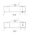
See, for example, FIG. 53, which shows an SNS lead L adjacent to one mass of material M1 for receiving distal anchor 20 of system 5, and adjacent to another mass of material M2 for anchoring proximal anchor 25 of system 5. FIG. 54 shows distal anchor 20 deployed against the exterior of a hard or soft mass of material M1 (e.g., a bone, soft tissue, a hard prosthesis, a soft prosthesis, etc). FIG. 55 shows distal anchor 20 deployed within the interior of a hard or soft mass of material M1 (e.g., a bone, soft tissue, a hard prosthesis, a soft prosthesis, etc.). FIG. 56 shows proximal anchor 25 deployed against the exterior of a hard or soft mass of material M2 (e.g., a bone, soft tissue, a hard prosthesis, a soft prosthesis, etc). FIG. 57 shows proximal anchor 25 deployed within the interior of a soft mass of material M2 (e.g., soft tissue, a soft prosthesis, etc.).
Thus, with the present invention, distal anchor 20 may be deployed through, or deployed within, any appropriate anatomical or prosthetic structure, and proximal anchor 25 may be deployed through, or deployed within, any appropriate anatomical or prosthetic structure, whereby to enable suture 30 to secure SNS lead L in the desired position within the patient's anatomy.
As seen in FIG. 58, suture 30 may simply extend over SNS lead L, holding the SNS lead against underlying tissue. Alternatively, as shown in FIG. 59, suture 30 may be wrapped around SNS lead L. Where suture 30 is wrapped around the SNS lead, it may be possible to support the SNS lead in position even in the absence of underlying tissue, since suture 30 can be used to suspend SNS lead L over a gap in the tissue. Furthermore, if desired, SNS lead L may include an associated mount, e.g., in the form of a web W extending laterally about the SNS lead, and distal anchor 20 and proximal anchor 25 may be advanced through web W prior to deployment through or into a mass of material (e.g., M1 or M2), in the manner shown in FIGS. 61 and 62.
FIGS. 63-70 show a variety of ways in which system 5 may be used to secure SNS lead L to adjacent structures.
Proximal Anchor Comprising Flexible Finger
As noted above, novel system 5 may be used to close a fissure in the annulus of an intervertebral disc, and/or to effect other anatomical repairs and/or other anatomical fixations, including anchoring sensory nerve stimulator (SNS) leads.
In another preferred form of the present invention, novel system 5 utilizes the aforementioned distal anchor 20 and the aforementioned suture 30 (and also the aforementioned inserter 15), but substitutes an alternative proximal anchor 25A (FIGS. 71 and 72) for the aforementioned proximal anchor 25.
More particularly, in this form of the invention, proximal anchor 25A comprises a generally cylindrical body 90A having a distal end 95A, a proximal end 100A and a generally circular side wall 105A. Distal end 95A terminates in a distal surface 110A. Proximal end 100A terminates in a proximal surface 120A. A vertical bore 126A passes completely through proximal anchor 25A. Vertical bore 126A is sized to slidably receive suture 30 therein. A recess 131A passes part way through proximal anchor 25A. A U-shaped slot 136A passes part way through proximal anchor 25A. Recess 131A and U-shaped slot 136A together define a flexible finger 141A. In this form of the invention, a gap 142A is formed between the inner tip 143A of flexible finger 141A and the edge 144A formed at the convergence of recess 131A and U-shaped slot 136A. Preferably gap 142A is sized so as to be approximately 50% of the width of suture 30 when flexible finger 141A is in its relaxed, unbiased condition (i.e., in the position shown in FIGS. 71 and 72) and when suture 30 is in its normal, uncompressed condition. A bottom horizontal slot 151A extends between vertical bore 126A and recess 131A. Bottom horizontal slot 151A may be stepped, comprising a wider outer portion 156A and a narrower inner portion 161A. If desired, wider outer portion 156A may be sized to slidably receive suture 30 therein so as to help keep proximal anchor 25A and suture 30 from binding when they are disposed within the aforementioned inserter 15, but narrower portion 161A may be sized to snugly receive suture 30 therein whereby to provide a light hold on suture 30 when suture 30 is disposed therein.
As seen in FIGS. 71 and 72, suture 30 is passed through proximal anchor 25A so that suture 30 extends down vertical bore 126A, through wider outer portion 156A of bottom horizontal slot 151A, up through recess 131A and out U-shaped slot 136A. Note that inasmuch as suture 30 has a diameter which is approximately twice the size of gap 142A formed between inner tip 143A of flexible finger 141A and edge 144A of proximal anchor 25A, flexible finger 141A will normally bear against the suture disposed in gap 142A. In this condition, the presence of the “oversized” suture 30 in the “undersized” gap 142A will cause flexible finger 141A to be flexed upwardly (from the angle of view of FIGS. 71 and 72) so as to accommodate suture 30, with inner tip 143A of flexible finger 141A capturing the suture against edge 144A of proximal anchor 25A. Note that some compression of suture 30 may occur in this condition.
In addition to the foregoing, it should be appreciated that suture 30 follows a non-linear path through proximal anchor 25A, and this non-linear path creates impedance to the passage of suture 30 through proximal anchor 25A.
In use, after the aforementioned distal anchor 20 has been deployed at the surgical site (preferably using the aforementioned inserter 15), proximal anchor 25A is also deployed at the surgical site (again, preferably using the aforementioned inserter 15), and then suture 30 is set by pulling proximally on suture 30. As suture 30 is pulled proximally, flexible finger 141A flexes away from the body of proximal anchor 25A, thereby allowing suture 30 to slide through recess 131A and U-shaped slot 136A (as well as through vertical bore 126A and wider outer portion 156A of bottom horizontal slot 151A). When the slack in suture 30 has been taken up, and suture 30 is thereafter tensioned further, where bottom horizontal slot 151A comprises a narrower portion 161A, suture 30 is pulled from wider outer portion 156A of bottom horizontal slot 151A into narrower portion 161A of bottom horizontal slot 151A so that suture 30 is snugly received therein, such that proximal anchor 25A provides a light hold on suture 30. When tension on the free end of suture 30 is thereafter relaxed, flexible finger 141A flexes back toward the body of proximal anchor 25A, whereby to lock suture 30 to proximal anchor 25A (i.e., with inner tip 143A of flexible finger 141A capturing the suture against edge 144A of proximal anchor 25A). In addition, inasmuch as suture 30 follows a non-linear path through proximal anchor 25A, the non-linear path creates impedance to the passage of suture 30 through proximal anchor 25A. In this way, suture 30 is secured to proximal anchor 25A. Thereafter, a half-hitch may be formed in suture 30 on the proximal side of proximal anchor 25A so as to further secure suture 30 to proximal anchor 25A.
Single Anchor Fixation
In another preferred form of the present invention, and looking now at FIG. 73, a single anchor system 500 may be used to secure an object (e.g., a sensory nerve stimulator “SNS” lead 505) to tissue (e.g., fascia 510). In this form of the invention, single anchor system 500 comprises a novel anchor 515 and a suture 520. Single anchor system 500 is preferably deployed using the aforementioned inserter 15 (or another appropriate inserter).
More particularly, anchor 515 comprises a generally cylindrical body 535 having a distal end 540, a proximal end 545 and a generally circular side wall 550. Distal end 540 terminates in a flat or somewhat inclined distal end surface 555 and a more inclined distal end surface 560. Flat or somewhat inclined distal end surface 555 is sufficiently large so as to render distal end 540 of anchor 515 substantially blunt (but, where distal end surface 555 is somewhat inclined, also having a tapered lead-in). Inclined distal end surface 560 is pitched at an appropriate angle (e.g., 30 degrees, 45 degrees, etc.) so as to cause anchor 515 to turn during deployment (in the same manner that the aforementioned distal anchor 20 comprises a corresponding inclined distal surface 60 for causing turning), as will hereinafter be discussed. Proximal end 545 terminates in an inclined proximal end surface 565.
A vertical bore 570 passes through anchor 515. Vertical bore 570 is sized to slidably receive suture 520 therein. A horizontal slot 575 extends between inclined distal end surface 560 and vertical bore 570. Horizontal slot 575 is preferably also sized to slidably receive suture 520 therein, and helps keep anchor 515 and suture 520 from binding when they are disposed within the aforementioned inserter 15. A pair of vertical bores 581, 583 are also disposed in anchor 515, proximal to vertical bore 570. Vertical bores 581, 583 are also sized to slidably receive suture 520 therein. A bottom horizontal slot 586 extends between vertical bore 581 and vertical bore 583.
Significantly, suture 520 follows a non-linear path through anchor 515, and this non-linear path creates impedance to the passage of suture 520 through anchor 515.
If desired, bottom horizontal slot 586 may be stepped, comprising a wider outer portion 587 and a narrower inner portion 588. Wider outer portion 587 may be sized to slidably receive suture 520 therein so as to help keep anchor 515 and suture 520 from binding when they are disposed within the aforementioned inserter 15, but narrower portion 588 may be sized to snugly receive suture 520 therein, whereby to provide a light hold on suture 520 when suture 520 is disposed therein.
As seen in FIG. 73, suture 520 has a distal end 591 terminating in a large ball (or knot) 592, and a proximal segment 593. Suture 520 is passed through anchor 515 so that so that large ball (or knot) 592 is disposed against the more inclined distal end surface 560, and the suture extends along horizontal slot 575 of anchor 515, up vertical bore 570 of anchor 515, around the object (e.g., a sensory nerve stimulator “SNS” lead 505) which is to be secured to tissue (e.g., fascia 510), down vertical bore 581, through bottom horizontal slot 586 (i.e., through wider outer portion 587 of bottom horizontal slot 586 where bottom horizontal slot is stepped), and up vertical bore 583.
In use, anchor 515 is deployed at the surgical site with suture 520 under tension so that anchor 515 is turned as it is ejected from the aforementioned inserter 15 (in the same manner that the aforementioned distal anchor 20 is turned as it is ejected from the aforementioned inserter 15), then suture 520 is tensioned by pulling proximally on proximal end 593 of suture 520. As suture 520 is tensioned, sensory nerve stimulator “SNS” lead 505 is secured against fascia 510 (i.e., by virtue of anchor 515 being set in fascia 510 and by virtue of lead 505 being captured to anchor 515 via suture 520). Note that suture 520 will be held against slippage relative to anchor 515 by virtue of the fact that suture 520 follows a non-linear path through anchor 515, and this non-linear path creates impedance to the passage of suture 520 through anchor 515. When suture 520 is thereafter tensioned further, and where bottom horizontal slot 586 comprises a narrower portion 588, suture 520 will be pulled from wider outer portion 587 of bottom horizontal slot 586 into narrower portion 588 of bottom horizontal slot 586 so that suture 520 is snugly received therein. This can provide an additional hold on suture 520. Thereafter, a half-hitch 594 is formed in suture 520 on the proximal side of anchor 520 so as to secure the fixation. In this form of the invention, half hitch 594 will provide the primary fixation of suture 520 to anchor 515, and the impedance created by the non-linear path of suture 520 through anchor 515 will provide significant additional fixation of suture 520. Where bottom horizontal slot 586 comprises a narrower portion 588, movement of suture 520 into narrower portion 588 can also provide a small additional holding force.
Single Anchor Fixation Utilizing Anchor Comprising Flexible Finger
In another preferred form of the present invention, and looking now at FIGS. 74-85, a single anchor system 600 may be used (e.g., with the aforementioned inserter 15) to secure an object (e.g., a sensory nerve stimulator SNS lead 605) to tissue (e.g., fascia 610). In this form of the invention, single anchor system 600 comprises a novel anchor 615 and a suture 620. Single anchor system 600 is preferably deployed using the aforementioned inserter 15 (or another appropriate inserter).
More particularly, anchor 615 comprises a generally cylindrical body 625 having a distal end 630, a proximal end 635 and a generally circular side wall 640. Distal end 630 terminates in a flat or somewhat inclined distal end surface 645 and a more inclined distal end surface 650. Flat or somewhat inclined distal end surface 645 is sufficiently large so as to render distal end 630 of anchor 615 substantially blunt (but, where distal end surface 645 is somewhat inclined, also having a tapered lead-in). Inclined distal end surface 650 is pitched at an appropriate angle (e.g., 30 degrees, 45 degrees, etc.) so as to cause anchor 615 to turn during deployment (in the same manner that the aforementioned distal anchor 20 comprises a corresponding inclined distal surface 60 for causing turning), as will hereinafter be discussed. Proximal end 635 terminates in an inclined proximal end surface 655.
A vertical bore 660 passes completely through anchor 615. Vertical bore 660 preferably intersects inclined distal end surface 650 and is sized to slidably receive suture 620 therein. A recess 665 passes part way through anchor 615. A U-shaped slot 670 passes part way through anchor 615. Recess 665 and U-shaped slot 670 together define a flexible finger 675. In this form of the invention, a gap 680 is formed between the inner tip 685 of flexible finger 675 and the edge 690 formed at the convergence of recess 665 and U-shaped slot 670. Preferably gap 680 is sized so as to be approximately 50% of the width of suture 620 when flexible finger 675 is in its relaxed, unbiased condition (i.e., in the position shown in FIGS. 78 and 83) and when suture 620 is in its normal, uncompressed condition. A bottom horizontal slot 695 extends between vertical bore 660 and recess 665. Bottom horizontal slot 695 may be stepped, comprising a wider outer portion 700 and a narrower inner portion 705. If desired, wider outer portion 700 may be sized to slidably receive suture 620 therein so as to help keep anchor 615 and suture 620 from binding when they are disposed within the aforementioned inserter 15, but narrower portion 705 may be sized to snugly receive suture 620 therein whereby to provide a light hold on suture 620 when suture 620 is disposed therein. Alternatively, bottom horizontal slot 695 may comprise a slot of uniform width with a chamfer lead-in.
As seen in FIG. 83, suture 620 has a distal end 710 terminating in a large ball or knot 715, a proximal segment 720, and an intermediate loop 725 which may be releasably secured to suture sled 280 of inserter 15. Suture 620 is passed through anchor 615 so that large ball or knot 715 is disposed against the more inclined distal end surface 650, and the suture extends into vertical bore 660, loops around to form loop 725 (which is preferably releasably secured to suture sled 280 of inserter 15) and extends back down vertical bore 660, through wider outer portion 700 of bottom horizontal slot 695 (if bottom horizontal slot 695 is stepped), up through recess 665 and out U-shaped slot 670. Note that inasmuch as suture 620 has a diameter which is approximately twice the size of gap 680 formed between inner tip 685 of flexible finger 675 and edge 690 of anchor 615, flexible finger 675 will normally bear against the suture disposed in gap 680. In this condition, the presence of the “oversized” suture 620 in the “undersized” gap 680 will cause flexible finger 675 to be flexed upwardly (from the angle of view of FIG. 83) so as to accommodate suture 620, with inner tip 685 of flexible finger 675 capturing the suture against edge 690 of anchor 615. Note that some compression of suture 620 may occur in this condition.
In addition to the foregoing, it should be appreciated that suture 620 follows a non-linear path through anchor 615, and this non-linear path creates impedance to the passage of suture 620 through anchor 615.
In use, anchor 615 is deployed at the surgical site with suture 620 under tension so that anchor 615 is turned as it is ejected from the aforementioned inserter 15 (in the same manner that the aforementioned distal anchor 20 is turned as it is ejected from the aforementioned inserter 15). In one preferred form of the invention, this is accomplished by releasably mounting loop 725 of suture 620 to suture sled 280 of inserter 15 during insertion of anchor 615. Then loop 725 of suture 620 is released from suture sled 280, SNS lead 605 is passed through loop 725, and then suture 620 is tensioned by pulling proximally on proximal end 720 of suture 620. As suture 620 is tensioned, flexible finger 675 flexes away from the body of anchor 615, thereby allowing suture 620 to slide through recess 680 and U-shaped slot 670 (as well as through vertical bore 660 and wider outer portion 700 of bottom horizontal slot 695). When the slack in suture 620 has been taken up, whereby to pull SNS lead 605 tight against fascia 610, and suture 620 is thereafter tensioned further, where bottom horizontal slot 695 comprises a narrower portion 705, suture 620 is pulled from wider outer portion 700 of bottom horizontal slot 695 into narrower portion 705 of bottom horizontal slot 695 so that suture 620 is snugly received therein, such that anchor 615 provides a light hold on suture 620. When tension on the free end of suture 620 is thereafter relaxed, flexible finger 675 flexes back toward the body of anchor 615, whereby to lock suture 620 to anchor 615 (i.e., with inner tip 685 of flexible finger 675 capturing the suture against edge 690 of anchor 615). In addition, inasmuch as suture 620 follows a non-linear path through anchor 615, the non-linear path creates impedance to the passage of suture 620 through anchor 615. In this way, suture 620 is secured to anchor 615. Thereafter, if desired, a half-hitch may be formed in suture 620 on the proximal side of anchor 615 so as to further secure suture 620 to anchor 615, and hence secure SNS lead 605 to fascia 610.
In one preferred form of the invention, single anchor system 600 is configured so that its failure mode comprises slipping, not breaking (i.e., suture 620 will slip relative to anchor 615 before anchor 615 will break).
And in one preferred form of the invention, anchor 615 comprises carbon fiber-reinforced PEEK (30%).
Furthermore, if desired, anchor 615 may comprise a radiopaque material so that anchor 615 is visible under X-ray visualization. By way of example but not limitation, a radiopaque element may be incorporated in the body of anchor 615. By way of further example but not limitation, a piece of Nitinol wire may be molded into anchor 615 so that the Nitinol wire extends through flexible finger 675 and into the adjoining body of anchor 615—in this form of the invention, the Nitinol wire reinforces flexible finger 675 at the same time that it provides a radiopaque element in anchor 615.
Inserter with Alternative Suture Sled
In the foregoing disclosure, inserter 15 is characterized as having a suture sled 280 which is spring mounted to handle 200. Suture sled 280 serves as a movable mount for securing the proximal portion of suture loop 320 (or suture loop 725) to handle 200, such that suture sled 280 can slide along handle 200 as distal anchor 20 (or anchor 615) is advanced into a mass of material (e.g., an intervertebral disc, a bone, soft tissue, etc.), and then be stopped relative to handle 200 so that distal anchor 20 (or anchor 615) is driven against ball 185 (or ball 715), whereby to facilitate turning of distal anchor 20 (or anchor 615) within the mass of material.
To this end, in the foregoing disclosure, suture sled 280 is characterized as being spring mounted to handle 200 so that suture sled 280 initially remains in a proximal position, whereby to hold suture 30 (or suture 620) under tension, until distal anchor 20 (or anchor 615) is driven distally by push rod 205 of inserter 15, whereupon suture sled 280 is permitted to move distally, against the power of spring 285, until distal anchor 20 (or anchor 615) is at the proper depth within the mass of material, whereupon distal movement of suture sled 280 is stopped, thereby stopping distal movement of ball 185 (or ball 715) and hence setting the depth of distal anchor 20 (or anchor 615).
However, if desired, spring 285 may be omitted, and other means may be provided for releasably holding suture sled 280 in a proximal position until distal anchor 20 (or anchor 615) is driven distally by push rod 205. By way of example but not limitation, suture sled 280 may be releasably held in a proximal position by means of a yielding stop finger, a ball-and-detent mechanism, or other releasable holding mechanism of the sort well known in the art.
Inserter with Impulse Driver
In the foregoing disclosure, inserter 15 is characterized as having a push rod 205 which is moved distally by manually pressing on thumb button 310 (e.g., in the manner of manually pressing on the plunger of a syringe), whereby to drive distal anchor 20 (or anchor 615) distally.
However, in some circumstances it can be desirable to drive distal anchor 20 (or anchor 615) with an impulse mechanism, so that an impulse of drive energy is applied to distal anchor 20 (or anchor 615). By way of example but not limitation, where distal anchor 20 (or anchor 615) is formed out of a material having limited strength (e.g., PEEK or PLLA), and where distal anchor 20 (or anchor 615) is to be set in a harder mass of material (e.g., bone), it can be helpful to set distal anchor 20 (or anchor 615) with an impulse mechanism.
To this end, and looking now at FIG. 86, inserter 15 may be provided with a tension spring 800 which is secured to proximal end 240 of handle 200 and to thumb button 310 of push rod 205. With such a construction, thumb button 310 may be pulled proximally, away from handle 200, so that tension spring 800 is stretched and then, when impulse energy is to be applied to distal anchor 20 (or anchor 615) via push rod 205, thumb button 310 is simply released, so that tension spring 800 applies impulse energy to thumb button 310 and hence causes push rod 205 to apply impulse energy to distal anchor 20 (or anchor 615).
MODIFICATIONS OF THE PREFERRED EMBODIMENTS
It should be understood that many additional changes in the details, materials, steps and arrangements of parts, which have been herein described and illustrated in order to explain the nature of the present invention, may be made by those skilled in the art while still remaining within the principles and scope of the invention.

Claims (71)

What is claimed is:
1. Apparatus for attaching a suture to an object, said apparatus comprising:
an anchor comprising a generally cylindrical body, a distal end and a proximal end, wherein said distal end comprises an inclined distal end surface, and a vertical bore extending through said generally cylindrical body, perpendicular to the longitudinal axis of said generally cylindrical body; and
a suture having a proximal end and a distal end, with an enlargement formed at said distal end, wherein said suture extends through said vertical bore of said anchor;
wherein said anchor further comprises a recess formed on one side of said generally cylindrical body and a U-shaped slot formed on the opposing side of said generally cylindrical body whereby to form a flexible finger extending distally within said generally cylindrical body, and further wherein a distal end of said finger is spaced from a bottom edge of said U-shaped slot of said generally cylindrical body.
2. Apparatus according to claim 1 further comprising an inserter, said inserter comprising:
a handle;
a tube mounted to said handle and extending distally therefrom, said tube being sized to receive said anchor;
a push rod slidably disposed within said tube; and
a suture sled movably mounted to said handle, said suture sled comprising means for releasably securing said suture to said suture sled.
3. Apparatus according to claim 2 further comprising releasable holding means for releasably holding said suture sled in a proximal position.
4. Apparatus according to claim 3 wherein said releasable holding means comprise a spring.
5. Apparatus according to claim 2 wherein said anchor is releasably disposed within said tube, and wherein the suture extending through said vertical bore of said anchor is releasably secured to said suture sled.
6. Apparatus according to claim 5 wherein said tube comprises an elongated opening for accommodating said suture.
7. Apparatus according to claim 6 wherein said handle comprises a passageway.
8. Apparatus according to claim 1 wherein said proximal end of said suture extends through said recess and through said U-shaped slot.
9. Apparatus according to claim 8 wherein said distal end of said flexible finger is spaced from said bottom edge of said U-shaped slot of said generally cylindrical body by a distance which is less than the diameter of said suture, such that said flexible finger applies a compressive force against said suture.
10. Apparatus according to claim 9 wherein the distance is approximately 50% of the diameter of the suture.
11. Apparatus according to claim 1 wherein said anchor further comprises a horizontally-extending slot formed in said anchor and in communication with said vertical bore and said recess.
12. Apparatus according to claim 11 wherein said horizontally-extending slot comprises a wider outer portion and a narrower inner portion.
13. Apparatus according to claim 1 wherein the wider outer portion is sized to slidably receive the suture, and further wherein the narrower inner portion is sized to snugly receive the suture.
14. Apparatus according to claim 1 wherein the object comprises tissue.
15. Apparatus according to claim 14 wherein the suture is configured to secure a sensory nerve stimulator lead to the tissue.
16. Apparatus according to claim 1 wherein said proximal end of said anchor comprises an inclined proximal end surface.
17. Apparatus according to claim 1 wherein said flexible finger comprises Nitinol.
18. A method for attaching a suture to an object, said method comprising:
providing apparatus comprising:
an anchor comprising a generally cylindrical body, a distal end and a proximal end, wherein said distal end comprises an inclined distal end surface, and a vertical bore extending through said generally cylindrical body, perpendicular to the longitudinal axis of said generally cylindrical body; and
a suture having a proximal end and a distal end, with an enlargement formed at said distal end, wherein said suture extends through said vertical bore of said anchor;
advancing said anchor into said object, with said suture and said enlargement advancing with said anchor;
while holding said suture and said enlargement in place, further advancing said anchor so that said inclined distal end surface of said anchor engages said enlargement and causes said anchor to turn relative to said object.
19. A method according to claim 18 wherein the object comprises tissue.
20. A method according to claim 19 wherein the suture secures a sensory nerve stimulator lead to the tissue.
21. A method according to claim 18 wherein said anchor further comprises a recess formed on one side of said generally cylindrical body and a U-shaped slot formed on the opposing side of said generally cylindrical body whereby to form a flexible finger extending distally within said generally cylindrical body, and further wherein a distal end of said finger is spaced from a bottom edge of said U-shaped slot of said generally cylindrical body.
22. A method according to claim 21 wherein said proximal end of said suture extends through said recess and through said U-shaped slot.
23. A method according to claim 22 wherein said distal end of said flexible finger is spaced from said bottom edge of said U-shaped slot of said generally cylindrical body by a distance which is less than the diameter of said suture, such that said flexible finger applies a compressive force against said suture.
24. A method according to claim 23 wherein the distance is approximately 50% of the diameter of the suture.
25. A method according to claim 21 wherein said anchor further comprises a horizontally-extending slot formed in said anchor and in communication with said vertical bore and said recess.
26. A method according to claim 25 wherein said horizontally-extending slot comprises a wider outer portion and a narrower inner portion.
27. A method according to claim 26 wherein the wider outer portion is sized to slidably receive the suture, and further wherein the narrower inner portion is sized to snugly receive the suture.
28. A method according to claim 26 wherein pulling proximally on said proximal end of said suture causes said suture to enter said narrower inner portion of said horizontally-extending slot formed in said anchor.
29. A method according to claim 18 further comprising an inserter, said inserter comprising:
a handle;
a tube mounted to said handle and extending distally therefrom, said tube being sized to receive said anchor;
a push rod slidably disposed within said tube; and
a suture sled movably mounted to said handle, said suture sled comprising means for releasably securing said suture to said suture sled.
30. A method according to claim 29 further comprising releasable holding means for releasably holding said suture sled in a proximal position.
31. A method according to claim 30 wherein said releasable holding means comprise a spring.
32. A method according to claim 29 wherein said anchor is releasably disposed within said tube, and wherein the suture extending through said vertical bore of said anchor is releasably secured to said suture sled.
33. A method according to claim 32 wherein said tube comprises an elongated opening for accommodating said suture.
34. A method according to claim 33 wherein said handle comprises a passageway.
35. A method according to claim 18 wherein said proximal end of said anchor comprises an inclined proximal end surface.
36. A method according to claim 18 wherein said flexible finger comprises Nitinol.
37. Apparatus for attaching a suture to an object, said apparatus comprising:
an anchor comprising a generally cylindrical body, a distal end and a proximal end, a vertical bore extending through said generally cylindrical body, perpendicular to the longitudinal axis of said generally cylindrical body, a recess formed on one side of said generally cylindrical body and a U-shaped slot formed on the opposing side of said generally cylindrical body whereby to form a flexible finger extending distally within said generally cylindrical body, and further wherein a distal end of said finger is spaced from a bottom portion of said U-shaped slot of said generally cylindrical body; and
a suture extending through said vertical bore, said recess and said U-shaped slot.
38. Apparatus according to claim 37 wherein said distal end of said anchor comprises an inclined distal end surface, and further wherein the suture comprises a proximal end and a distal end, with an enlargement formed at said distal end.
39. Apparatus according to claim 37 wherein said distal end of said flexible finger is spaced from said bottom edge of said U-shaped slot of said generally cylindrical body by a distance which is less than the diameter of said suture, such that said flexible finger applies a compressive force against said suture.
40. Apparatus according to claim 39 wherein the distance is approximately 50% of the diameter of the suture.
41. Apparatus according to claim 37 wherein said anchor further comprises a horizontally-extending slot formed in said anchor and in communication with said vertical bore and said recess.
42. Apparatus according to claim 41 wherein said horizontally-extending slot comprises a wider outer portion and a narrower inner portion.
43. Apparatus according to claim 42 wherein the wider outer portion is sized to slidably receive the suture, and further wherein the narrower inner portion is sized to snugly receive the suture.
44. Apparatus according to claim 37 further comprising an inserter, said inserter comprising:
a handle;
a tube mounted to said handle and extending distally therefrom, said tube being sized to receive said anchor;
a push rod slidably disposed within said tube; and
a suture sled movably mounted to said handle, said suture sled comprising means for releasably securing said suture to said suture sled.
45. Apparatus according to claim 44 further comprising releasable holding means for releasably holding said suture sled in a proximal position.
46. Apparatus according to claim 45 wherein said releasable holding means comprise a spring.
47. Apparatus according to claim 44 wherein said anchor is releasably disposed within said tube, and wherein the suture extending through said vertical bore of said anchor is releasably secured to said suture sled.
48. Apparatus according to claim 47 wherein said tube comprises an elongated opening for accommodating said suture.
49. Apparatus according to claim 48 wherein said handle comprises a passageway.
50. Apparatus according to claim 37 wherein the object comprises tissue.
51. Apparatus according to claim 50 wherein the suture is configured to secure a sensory nerve stimulator lead to the tissue.
52. Apparatus according to claim 37 wherein said proximal end of said anchor comprises an inclined proximal end surface.
53. Apparatus according to claim 37 wherein said flexible finger comprises Nitinol.
54. A method for attaching a suture to an object, said method comprising
providing apparatus comprising:
an anchor comprising a generally cylindrical body, a distal end and a proximal end, a vertical bore extending through said generally cylindrical body, perpendicular to the longitudinal axis of said generally cylindrical body, a recess formed on one side of said generally cylindrical body and a U-shaped slot formed on the opposing side of said generally cylindrical body whereby to form a flexible finger extending distally within said generally cylindrical body, and further wherein a distal end of said finger is spaced from a bottom edge of said U-shaped slot of said generally cylindrical body; and
a suture extending through said vertical bore, said recess and said U-shaped slot;
advancing said anchor into the object; and
pulling on said proximal end of said suture.
55. A method according to claim 54 wherein said distal end of said anchor comprises an inclined distal end surface, and further wherein the suture comprises a proximal end and a distal end, with an enlargement formed at said distal end.
56. A method according to claim 54 wherein said distal end of said flexible finger is spaced from said bottom edge of said U-shaped slot of said generally cylindrical body by a distance which is less than the diameter of said suture, such that said flexible finger applies a compressive force against said suture.
57. A method according to claim 56 wherein the distance is approximately 50% of the diameter of the suture.
58. A method according to claim 54 wherein said anchor further comprises a horizontally-extending slot formed in said anchor and in communication with said vertical bore and said recess.
59. A method according to claim 58 wherein said horizontally-extending slot comprises a wider outer portion and a narrower inner portion.
60. A method according to claim 59 wherein the wider outer portion is sized to slidably receive the suture, and further wherein the narrower inner portion is sized to snugly receive the suture.
61. A method according to claim 59 wherein pulling proximally on said proximal end of said suture causes said suture to enter said narrower inner portion of said horizontally-extending slot formed in said anchor.
62. A method according to claim 54 further comprising an inserter, said inserter comprising:
a handle;
a tube mounted to said handle and extending distally therefrom, said tube being sized to receive said anchor;
a push rod slidably disposed within said tube; and
a suture sled movably mounted to said handle, said suture sled comprising means for releasably securing said suture to said suture sled.
63. A method according to claim 62 further comprising releasable holding means for releasably holding said suture sled in a proximal position.
64. A method according to claim 63 wherein said releasable holding means comprise a spring.
65. A method according to claim 62 wherein said anchor is releasably disposed within said tube, and wherein the suture extending through said vertical bore of said anchor is releasably secured to said suture sled.
66. A method according to claim 65 wherein said tube comprises an elongated opening for accommodating said suture.
67. A method according to claim 66 wherein said handle comprises a passageway.
68. A method according to claim 54 wherein the object comprises tissue.
69. A method according to claim 68 wherein the suture secures a sensory nerve stimulator lead to the tissue.
70. A method according to claim 54 wherein said proximal end of said anchor comprises an inclined proximal end surface.
71. A method according to claim 54 wherein said flexible finger comprises Nitinol.
US14/461,992 2012-10-31 2014-08-18 Method and apparatus for closing a fissure in the annulus of an intervertebral disc, and/or for effecting other anatomical repairs and/or fixations Active 2034-04-26 US9949734B2 (en)

Priority Applications (5)

Application Number Priority Date Filing Date Title
US14/461,992 US9949734B2 (en) 2012-10-31 2014-08-18 Method and apparatus for closing a fissure in the annulus of an intervertebral disc, and/or for effecting other anatomical repairs and/or fixations
US15/827,322 US10786235B2 (en) 2012-10-31 2017-11-30 Method and apparatus for closing a fissure in the annulus of an intervertebral disc, and/or for effecting other anatomical repairs and/or fixations
US15/961,309 US10863979B2 (en) 2012-10-31 2018-04-24 Method and apparatus for closing a fissure in the annulus of an intervertebral disc, and/or for effecting other anatomical repairs and/or fixations
US16/681,420 US20200147367A1 (en) 2012-10-31 2019-11-12 Method and apparatus for closing a fissure in the annulus of an intervertebral disc, and/or for effecting other anatomical repairs and/or fixations
US17/471,046 US20220167960A1 (en) 2012-10-31 2021-09-09 Method and apparatus for closing a fissure in the annulus of an intervertebral disc, and/or for effecting other anatomical repairs and/or fixations

Applications Claiming Priority (6)

Application Number Priority Date Filing Date Title
US201261720593P 2012-10-31 2012-10-31
US201361866955P 2013-08-16 2013-08-16
US14/068,406 US9433404B2 (en) 2012-10-31 2013-10-31 Method and apparatus for closing fissures in the annulus fibrosus
US201361915433P 2013-12-12 2013-12-12
US201461984431P 2014-04-25 2014-04-25
US14/461,992 US9949734B2 (en) 2012-10-31 2014-08-18 Method and apparatus for closing a fissure in the annulus of an intervertebral disc, and/or for effecting other anatomical repairs and/or fixations

Related Parent Applications (1)

Application Number Title Priority Date Filing Date
US14/068,406 Continuation-In-Part US9433404B2 (en) 2012-10-31 2013-10-31 Method and apparatus for closing fissures in the annulus fibrosus

Related Child Applications (2)

Application Number Title Priority Date Filing Date
US15/827,322 Continuation-In-Part US10786235B2 (en) 2012-10-31 2017-11-30 Method and apparatus for closing a fissure in the annulus of an intervertebral disc, and/or for effecting other anatomical repairs and/or fixations
US15/961,309 Continuation US10863979B2 (en) 2012-10-31 2018-04-24 Method and apparatus for closing a fissure in the annulus of an intervertebral disc, and/or for effecting other anatomical repairs and/or fixations

Publications (3)

Publication Number Publication Date
US20150051621A1 US20150051621A1 (en) 2015-02-19
US20170135690A9 US20170135690A9 (en) 2017-05-18
US9949734B2 true US9949734B2 (en) 2018-04-24

Family

ID=52467341

Family Applications (2)

Application Number Title Priority Date Filing Date
US14/461,992 Active 2034-04-26 US9949734B2 (en) 2012-10-31 2014-08-18 Method and apparatus for closing a fissure in the annulus of an intervertebral disc, and/or for effecting other anatomical repairs and/or fixations
US15/961,309 Active 2033-12-28 US10863979B2 (en) 2012-10-31 2018-04-24 Method and apparatus for closing a fissure in the annulus of an intervertebral disc, and/or for effecting other anatomical repairs and/or fixations

Family Applications After (1)

Application Number Title Priority Date Filing Date
US15/961,309 Active 2033-12-28 US10863979B2 (en) 2012-10-31 2018-04-24 Method and apparatus for closing a fissure in the annulus of an intervertebral disc, and/or for effecting other anatomical repairs and/or fixations

Country Status (5)

Country Link
US (2) US9949734B2 (en)
EP (1) EP3033014B1 (en)
AU (2) AU2014306454B2 (en)
CA (1) CA2920546A1 (en)
WO (1) WO2015024013A2 (en)

Cited By (2)

* Cited by examiner, † Cited by third party
Publication number Priority date Publication date Assignee Title
US10786235B2 (en) 2012-10-31 2020-09-29 Anchor Innovation Medical, Inc. Method and apparatus for closing a fissure in the annulus of an intervertebral disc, and/or for effecting other anatomical repairs and/or fixations
US10863979B2 (en) 2012-10-31 2020-12-15 Anchor Innovation Medical, Inc. Method and apparatus for closing a fissure in the annulus of an intervertebral disc, and/or for effecting other anatomical repairs and/or fixations

Families Citing this family (15)

* Cited by examiner, † Cited by third party
Publication number Priority date Publication date Assignee Title
US10588691B2 (en) 2012-09-12 2020-03-17 Relievant Medsystems, Inc. Radiofrequency ablation of tissue within a vertebral body
US20200147367A1 (en) * 2012-10-31 2020-05-14 Anchor Innovation Medical, Inc. Method and apparatus for closing a fissure in the annulus of an intervertebral disc, and/or for effecting other anatomical repairs and/or fixations
CA3093398C (en) 2012-11-05 2022-05-24 Relievant Medsystems, Inc. Systems and methods for creating curved paths through bone and modulating nerves within the bone
US9724151B2 (en) 2013-08-08 2017-08-08 Relievant Medsystems, Inc. Modulating nerves within bone using bone fasteners
KR20180108661A (en) * 2016-02-05 2018-10-04 듀라 탭 엘엘씨 Apparatus and method for suture placement
US20180085110A1 (en) * 2016-09-28 2018-03-29 Arthrex, Inc. Instrument for manual insertion of button
AU2017353857A1 (en) 2016-11-02 2019-06-06 Anchor Innovation Medical, Inc. Method and apparatus for anchoring electrical leads and/or other elongated flexible elements to patient skin
CA3044663A1 (en) * 2016-11-30 2018-06-07 Anchor Innovation Medical, Inc. Method and apparatus for closing a fissure in the annulus of an intervertebral disc
CN107714116B (en) * 2017-09-07 2020-07-14 深圳市第二人民医院 Laparoscope stitching instrument
WO2021050767A1 (en) 2019-09-12 2021-03-18 Relievant Medsystems, Inc. Systems and methods for tissue modulation
US11382613B1 (en) 2021-04-08 2022-07-12 Integrity Orthopaedics, Inc. Methods for transtendinous implantation of knotless micro suture anchors and anchor arrays
US11382612B1 (en) 2021-04-08 2022-07-12 Integrity Orthopaedics, Inc. Method for creating a tensionable and lockable suture anchor array for anatomical attachment of tissue to bone
US11375992B1 (en) 2021-04-08 2022-07-05 Integrity Orthopaedics, Inc. Cartridge device for suture anchor and suture management during implantation of a micro suture anchor array
US11375995B1 (en) 2021-04-08 2022-07-05 Integrity Orthopaedics, Inc. Locking suture construct for tensioned suture to suture stitches in anchor arrays for attaching soft tissue to bone
US11375991B1 (en) 2021-04-08 2022-07-05 Integrity Orthopaedics, Inc. Tensionable and lockable micro suture anchors and anchor arrays for anatomical attachment of soft tissue to bone

Citations (227)

* Cited by examiner, † Cited by third party
Publication number Priority date Publication date Assignee Title
US4235238A (en) 1978-05-11 1980-11-25 Olympus Optical Co., Ltd. Apparatus for suturing coeliac tissues
US4413359A (en) 1981-03-04 1983-11-08 Koken Co., Ltd. Impermeable laminate membrane
US4512338A (en) 1983-01-25 1985-04-23 Balko Alexander B Process for restoring patency to body vessels
US4663358A (en) 1985-05-01 1987-05-05 Biomaterials Universe, Inc. Porous and transparent poly(vinyl alcohol) gel and method of manufacturing the same
US4669473A (en) 1985-09-06 1987-06-02 Acufex Microsurgical, Inc. Surgical fastener
US4772287A (en) 1987-08-20 1988-09-20 Cedar Surgical, Inc. Prosthetic disc and method of implanting
US4834757A (en) 1987-01-22 1989-05-30 Brantigan John W Prosthetic implant
US4932969A (en) 1987-01-08 1990-06-12 Sulzer Brothers Limited Joint endoprosthesis
US5015255A (en) 1989-05-10 1991-05-14 Spine-Tech, Inc. Spinal stabilization method
US5041129A (en) 1990-07-02 1991-08-20 Acufex Microsurgical, Inc. Slotted suture anchor and method of anchoring a suture
US5047055A (en) 1990-12-21 1991-09-10 Pfizer Hospital Products Group, Inc. Hydrogel intervertebral disc nucleus
US5100422A (en) 1989-05-26 1992-03-31 Impra, Inc. Blood vessel patch
US5147374A (en) 1991-12-05 1992-09-15 Alfredo Fernandez Prosthetic mesh patch for hernia repair
US5171278A (en) 1991-02-22 1992-12-15 Madhavan Pisharodi Middle expandable intervertebral disk implants
US5192326A (en) 1990-12-21 1993-03-09 Pfizer Hospital Products Group, Inc. Hydrogel bead intervertebral disc nucleus
US5258043A (en) 1987-07-20 1993-11-02 Regen Corporation Method for making a prosthetic intervertebral disc
US5304194A (en) 1991-10-02 1994-04-19 Target Therapeutics Vasoocclusion coil with attached fibrous element(s)
US5342394A (en) 1990-05-16 1994-08-30 Olympus Optical Co., Ltd. Apparatus for blocking a vein branch and method of blocking a vein branch
US5370660A (en) 1993-11-01 1994-12-06 Cordis Corporation Apparatus and method for delivering a vessel plug into the body of a patient
US5390683A (en) 1991-02-22 1995-02-21 Pisharodi; Madhavan Spinal implantation methods utilizing a middle expandable implant
US5413585A (en) 1992-12-22 1995-05-09 Pagedas; Anthony C. Self locking suture lock
US5425772A (en) 1993-09-20 1995-06-20 Brantigan; John W. Prosthetic implant for intervertebral spinal fusion
US5489307A (en) 1993-02-10 1996-02-06 Spine-Tech, Inc. Spinal stabilization surgical method
US5540715A (en) 1992-07-16 1996-07-30 Sherwood Medical Company Device for sealing hemostatic incisions
US5545229A (en) 1988-08-18 1996-08-13 University Of Medicine And Dentistry Of Nj Functional and biocompatible intervertebral disc spacer containing elastomeric material of varying hardness
US5549679A (en) 1994-05-20 1996-08-27 Kuslich; Stephen D. Expandable fabric implant for stabilizing the spinal motion segment
US5562736A (en) 1994-10-17 1996-10-08 Raymedica, Inc. Method for surgical implantation of a prosthetic spinal disc nucleus
US5645597A (en) 1995-12-29 1997-07-08 Krapiva; Pavel I. Disc replacement method and apparatus
US5681310A (en) 1994-07-20 1997-10-28 Yuan; Hansen A. Vertebral auxiliary fixation device having holding capability
US5702454A (en) 1993-04-21 1997-12-30 Sulzer Orthopadie Ag Process for implanting an invertebral prosthesis
US5716418A (en) 1992-08-22 1998-02-10 Henkel Kommanditgesellschaft Auf Aktien Coloring of keratin-containing fibers with preparations which contain alkyl glycosides and oxidation dye precursors
US5735877A (en) 1996-02-28 1998-04-07 Pagedas; Anthony C. Self locking suture lock
US5800550A (en) 1996-03-13 1998-09-01 Sertich; Mario M. Interbody fusion cage
US5800549A (en) 1997-04-30 1998-09-01 Howmedica Inc. Method and apparatus for injecting an elastic spinal implant
US5824093A (en) 1994-10-17 1998-10-20 Raymedica, Inc. Prosthetic spinal disc nucleus
US5827328A (en) 1996-11-22 1998-10-27 Buttermann; Glenn R. Intervertebral prosthetic device
US5879366A (en) 1996-12-20 1999-03-09 W.L. Gore & Associates, Inc. Self-expanding defect closure device and method of making and using
US5916225A (en) 1994-09-29 1999-06-29 Surgical Sense, Inc. Hernia mesh patch
US5976186A (en) 1994-09-08 1999-11-02 Stryker Technologies Corporation Hydrogel intervertebral disc nucleus
US5976174A (en) 1997-12-15 1999-11-02 Ruiz; Carlos E. Medical hole closure device and methods of use
US6015428A (en) 1997-06-03 2000-01-18 Anthony C. Pagedas Integrally formed suture and suture lock
US6024754A (en) 1996-01-18 2000-02-15 Target Therapeutics Inc. Aneurysm closure method
US6066160A (en) 1998-11-23 2000-05-23 Quickie Llc Passive knotless suture terminator for use in minimally invasive surgery and to facilitate standard tissue securing
US6224630B1 (en) 1998-05-29 2001-05-01 Advanced Bio Surfaces, Inc. Implantable tissue repair device
US6235107B1 (en) 1997-06-16 2001-05-22 Imerys Pigments, Inc. Method for separating mixture of finely divided minerals and product thereof
US6245107B1 (en) 1999-05-28 2001-06-12 Bret A. Ferree Methods and apparatus for treating disc herniation
US6245106B1 (en) 1998-10-29 2001-06-12 Allergan Sales, Inc. Intraocular lenses made from polymeric compositions and monomers useful in said compositions
US20020019649A1 (en) 1999-12-02 2002-02-14 Smith & Nephew, Inc., Delaware Corporation Closure device and method for tissue repair
US20020032155A1 (en) 2000-06-30 2002-03-14 Ferree Bret A. Method of treating disc herniation and disc degeneration with concentrated growth and differentiation factors
US6371990B1 (en) 1999-10-08 2002-04-16 Bret A. Ferree Annulus fibrosis augmentation methods and apparatus
US6402750B1 (en) 2000-04-04 2002-06-11 Spinlabs, Llc Devices and methods for the treatment of spinal disorders
US6419704B1 (en) 1999-10-08 2002-07-16 Bret Ferree Artificial intervertebral disc replacement methods and apparatus
US6423065B2 (en) 2000-02-25 2002-07-23 Bret A. Ferree Cross-coupled vertebral stabilizers including cam-operated cable connectors
US6425919B1 (en) 1999-08-18 2002-07-30 Intrinsic Orthopedics, Inc. Devices and methods of vertebral disc augmentation
US20020128713A1 (en) 1999-08-13 2002-09-12 Bret Ferree Spinal fusion cage with lordosis correction
US6454804B1 (en) 1999-10-08 2002-09-24 Bret A. Ferree Engineered tissue annulus fibrosis augmentation methods and apparatus
US20020151896A1 (en) 2001-03-27 2002-10-17 Ferree Bret A. Hinged anterior thoracic/lumbar plate
US20020151981A1 (en) 1999-10-14 2002-10-17 Ferree Bret A. Transplantation of engineered meniscus tissue to the intervertebral disc
US20020156533A1 (en) 1999-10-08 2002-10-24 Ferree Bret A. Natural and synthetic supplements to engineered annulus and disc tissues
US20020156532A1 (en) 1999-10-08 2002-10-24 Ferree Bret A. Supplementing engineered annulus tissues with autograft or allograft tendons
US20020165542A1 (en) 1999-10-08 2002-11-07 Ferree Bret A. Annulus fibrosis augmentation methods and apparatus
US20030004574A1 (en) 1999-10-08 2003-01-02 Ferree Bret A. Disc and annulus augmentation using biologic tissue
US6508839B1 (en) 1999-08-18 2003-01-21 Intrinsic Orthopedics, Inc. Devices and methods of vertebral disc augmentation
US20030040796A1 (en) 1999-10-08 2003-02-27 Ferree Bret A. Devices used to treat disc herniation and attachment mechanisms therefore
US20030074076A1 (en) 1999-10-08 2003-04-17 Ferree Bret A. Artificial intervertebral disc replacements with endplates
US20030078579A1 (en) 2001-04-19 2003-04-24 Ferree Bret A. Annular repair devices and methods
US6579291B1 (en) 2000-10-10 2003-06-17 Spinalabs, Llc Devices and methods for the treatment of spinal disorders
US6592625B2 (en) 1999-10-20 2003-07-15 Anulex Technologies, Inc. Spinal disc annulus reconstruction method and spinal disc annulus stent
US20030167062A1 (en) 2003-03-13 2003-09-04 Gambale Richard A Suture clips,delivery devices and methods
US20030185812A1 (en) 2000-06-30 2003-10-02 Ferree Bret A. Method of treating dural leaks with platelet-rich plasma (PRP)
US20030191536A1 (en) 1999-10-08 2003-10-09 Ferree Bret A. Artificial intervertebral disc replacements incorporating reinforced wall sections
US20030195631A1 (en) 2002-04-12 2003-10-16 Ferree Bret A. Shape-memory spacers for artificial disc replacements
WO2003088876A2 (en) 2002-04-16 2003-10-30 Sdgi Holdings, Inc. Annulus repair systems and techniques
US20030204260A1 (en) 2002-04-30 2003-10-30 Ferree Bret A. Methods and apparatus for preventing the migration of intradiscal devices
US6652585B2 (en) 2001-02-28 2003-11-25 Sdgi Holdings, Inc. Flexible spine stabilization system
US20040010318A1 (en) 2002-05-15 2004-01-15 Ferree Bret A. Conformable endplates for artificial disc replacement (ADR) devices and other applications
US6689125B1 (en) 2000-04-04 2004-02-10 Spinalabs, Llc Devices and methods for the treatment of spinal disorders
US6719797B1 (en) 1999-08-13 2004-04-13 Bret A. Ferree Nucleus augmentation with in situ formed hydrogels
US6723335B1 (en) 2000-04-07 2004-04-20 Jeffrey William Moehlenbruck Methods and compositions for treating intervertebral disc degeneration
US6733531B1 (en) 2000-10-20 2004-05-11 Sdgi Holdings, Inc. Anchoring devices and implants for intervertebral disc augmentation
US20040092945A1 (en) 2002-04-10 2004-05-13 Ferree Bret A. Implant integrity measurement apparatus
US20040093092A1 (en) 1999-10-08 2004-05-13 Ferree Bret A. Rotator cuff repair using engineered tissues
US20040093087A1 (en) 2002-11-05 2004-05-13 Ferree Bret A. Fluid-filled artificial disc replacement (ADR)
US20040097980A1 (en) 1999-05-28 2004-05-20 Ferree Bret A. Methods and apparatus for treating disc herniation and preventing the extrusion of interbody bone graft
US20040138753A1 (en) 2003-01-07 2004-07-15 Ferree Bret A. Artificial disc replacements with articulating components
US20040143334A1 (en) 2003-01-08 2004-07-22 Ferree Bret A. Artificial disc replacements (ADRS) with features to enhance longevity and prevent extrusion
US20040148028A1 (en) 2002-12-19 2004-07-29 Ferree Bret A. Artificial disc replacement (ADR) extraction methods and apparatus
US20040186573A1 (en) 1999-10-08 2004-09-23 Ferree Bret A. Annulus fibrosis augmentation methods and apparatus
US20040186577A1 (en) 2003-01-29 2004-09-23 Ferree Bret A. In situ artificaial disc replacements and other prosthetic components
US6805695B2 (en) 2000-04-04 2004-10-19 Spinalabs, Llc Devices and methods for annular repair of intervertebral discs
US20040230310A1 (en) 1999-08-13 2004-11-18 Ferree Bret A. Use of morphogenic proteins to treat human disc disease
US6821276B2 (en) 1999-08-18 2004-11-23 Intrinsic Therapeutics, Inc. Intervertebral diagnostic and manipulation device
US20040236342A1 (en) 2002-04-23 2004-11-25 Ferree Bret A. Device to assess ADR motion
US20040249461A1 (en) 1999-08-13 2004-12-09 Ferree Bret A. Coupled artificial disc replacements methods and apparatus
US20040244806A1 (en) 2003-06-09 2004-12-09 Ferree Bret A. Treating disc herniation and other conditions with leukocytes
US20040249465A1 (en) 2003-06-06 2004-12-09 Ferree Bret A. Methods and apparatus for total disc replacements with oblique keels
US20040249459A1 (en) 2003-06-02 2004-12-09 Ferree Bret A. Nucleus replacements with asymmetrical stiffness
US20040260396A1 (en) 1999-10-08 2004-12-23 Ferree Bret A. Artificial disc and joint replacements with modular cushioning components
US20050033338A1 (en) 2003-06-19 2005-02-10 Ferree Bret A. Surgical instruments particularly suited to severing ligaments and fibrous tissues
US20050065089A1 (en) 2000-06-30 2005-03-24 Ferree Bret A. TGF-beta activation and use
DE10340150A1 (en) 2003-08-26 2005-03-31 Aesculap Ag & Co. Kg Implant for closing an opening of the annulus fibrosus
US6878167B2 (en) 2002-04-24 2005-04-12 Bret A. Ferree Methods and apparatus for placing intradiscal devices
US6883520B2 (en) 1999-08-18 2005-04-26 Intrinsic Therapeutics, Inc. Methods and apparatus for dynamically stable spinal implant
US20050165484A1 (en) 2004-01-22 2005-07-28 Ferree Bret A. Artificial disc replacement (ADR) fixation methods and apparatus
US6936072B2 (en) 1999-08-18 2005-08-30 Intrinsic Therapeutics, Inc. Encapsulated intervertebral disc prosthesis and methods of manufacture
US20050256582A1 (en) 1999-10-08 2005-11-17 Ferree Bret A Spinal implants, including devices that reduce pressure on the annulus fibrosis
US20050261773A1 (en) 2002-05-15 2005-11-24 Ferree Bret A Lateral-approach artificial disc replacements
US20060004454A1 (en) 2002-04-24 2006-01-05 Ferree Bret A Assembled disc spacers
US7004945B2 (en) 2001-11-01 2006-02-28 Spinewave, Inc. Devices and methods for the restoration of a spinal disc
US7004970B2 (en) 1999-10-20 2006-02-28 Anulex Technologies, Inc. Methods and devices for spinal disc annulus reconstruction and repair
US20060052870A1 (en) 2004-09-09 2006-03-09 Ferree Bret A Methods and apparatus to prevent movement through artificial disc replacements
WO2006028986A2 (en) 2004-09-02 2006-03-16 Crosstrees Medical, Inc. Device and method for distraction of the spinal disc space
US20060064169A1 (en) 2002-09-10 2006-03-23 Ferree Bret A Shock-absorbing joint and spine replacements
US7033393B2 (en) 2002-06-27 2006-04-25 Raymedica, Inc. Self-transitioning spinal disc anulus occulsion device and method of use
US7052516B2 (en) 1999-10-20 2006-05-30 Anulex Technologies, Inc. Spinal disc annulus reconstruction method and deformable spinal disc annulus stent
US20060247778A1 (en) 2005-01-26 2006-11-02 Ferree Bret A Intradiscal devices including spacers facilitating posterior-lateral and other insertion approaches
US20060247665A1 (en) 1999-05-28 2006-11-02 Ferree Bret A Methods and apparatus for treating disc herniation and preventing the extrusion of interbody bone graft
WO2007001936A2 (en) 2005-06-20 2007-01-04 Sutura, Inc. Method and apparatus for applying a knot to a suture
US20070027471A1 (en) 1999-05-28 2007-02-01 Ferree Bret A Methods and apparatus for treating disc herniation and preventing the extrusion of interbody bone graft
US20070055375A1 (en) 2005-09-02 2007-03-08 Anova Corporation Methods and apparatus for reconstructing the annulus fibrosis
US20070067040A1 (en) 2005-09-02 2007-03-22 Anova Corporation Methods and apparatus for reconstructing the anulus fibrosus
US7198047B2 (en) 1999-08-18 2007-04-03 Intrinsic Therapeutics, Inc. Anchored anulus method
US7201775B2 (en) 2002-09-24 2007-04-10 Bogomir Gorensek Stabilizing device for intervertebral disc, and methods thereof
US7226481B2 (en) 2000-07-21 2007-06-05 Spineology, Inc. Expandable porous mesh bag device and methods of use for reduction, filling, fixation, and supporting of bone
US20070135920A1 (en) 2005-12-08 2007-06-14 Anova Corporation Sutures for use in the repair of defects in the anulus fibrosus
US7232455B2 (en) 1996-04-10 2007-06-19 Depuy Mitek, Inc. Wedge shaped suture anchor and method of implantation
US20070168043A1 (en) 2006-01-13 2007-07-19 Anova Corporation Percutaneous cervical disc reconstruction
US20070179530A1 (en) * 2006-01-31 2007-08-02 Tai Tieu System, apparatus, and method for fastening tissue
US7267688B2 (en) 2002-10-22 2007-09-11 Ferree Bret A Biaxial artificial disc replacement
US20070219558A1 (en) 2006-03-15 2007-09-20 Allen Deutsch Method and apparatus for arthroscopic surgery using suture anchors
US20070276494A1 (en) 2006-05-26 2007-11-29 Anova Corporation Fastening assemblies for disc herniation repair and methods of use
US20070288040A1 (en) 2006-06-13 2007-12-13 Anova Corporation Devices for disc herniation repair and methods of use
US20080014179A1 (en) 2006-07-11 2008-01-17 Ferree Bret A Tissue transplantation compositions and methods
US20080097479A1 (en) 2006-10-20 2008-04-24 Raimar Boehlke Device and method for vascular closure
US20080125780A1 (en) 2006-11-28 2008-05-29 Ferree Bret A Methods of posterior fixation and stabilization of a spinal segment
US20080125779A1 (en) 2006-11-28 2008-05-29 Ferree Bret A Methods of anterior fixation and stabilization of a spinal segment
US20080140126A1 (en) 2002-10-03 2008-06-12 Ferree Bret A Annular repair devices and methods
US20080140123A1 (en) 2006-11-28 2008-06-12 Ferree Bret A Methods and apparatus for stabilizing a spinal segment
US20080195151A1 (en) 2007-02-13 2008-08-14 Ferree Bret A Methods of Bone, Joint, and Ligament Reconstruction
US20080221686A1 (en) 1999-10-08 2008-09-11 Ferree Bret A Devices used to treat disc herniation and attachment mechanisms therefore
US20080243220A1 (en) 2007-03-28 2008-10-02 Advanced Bionics Corporation Lead anchor for implantable stimulation devices
US7445634B2 (en) 2000-10-27 2008-11-04 Warsaw Orthopedic, Inc. Annulus repair systems and methods
US7465318B2 (en) 2004-04-15 2008-12-16 Soteira, Inc. Cement-directing orthopedic implants
US20080311114A1 (en) 1999-08-13 2008-12-18 Ferree Bret A Use of morphogenic proteins to treat human disc disease
US20090012591A1 (en) 2007-07-05 2009-01-08 Advanced Bionics Corporation Lead with contacts formed by coiled conductor and methods of manufacture and use
US20090024165A1 (en) 2007-07-17 2009-01-22 Ferree Bret A Methods of annulus and ligament reconstruction using flexible devices
US7500978B2 (en) 2003-06-20 2009-03-10 Intrinsic Therapeutics, Inc. Method for delivering and positioning implants in the intervertebral disc environment
US7547326B2 (en) 2005-04-29 2009-06-16 Jmea Corporation Disc annulus repair system
US7553329B2 (en) 1999-08-18 2009-06-30 Intrinsic Therapeutics, Inc. Stabilized intervertebral disc barrier
US7556650B2 (en) 2004-06-29 2009-07-07 Spine Wave, Inc. Methods for injecting a curable biomaterial into an intervertebral space
US20090216306A1 (en) 2008-02-21 2009-08-27 Boston Scientific Neuromodulation Corporation Temporary neurostimulation lead identification device
US20090222073A1 (en) 2007-12-21 2009-09-03 Boston Scientific Neuromodulation Corporation Neurostimulation lead with stiffened proximal array
US7601172B2 (en) 2005-06-15 2009-10-13 Ouroboros Medical, Inc. Mechanical apparatus and method for artificial disc replacement
US7608108B2 (en) 2005-04-29 2009-10-27 Jmea Corporation Tissue repair system
US7615076B2 (en) 1999-10-20 2009-11-10 Anulex Technologies, Inc. Method and apparatus for the treatment of the intervertebral disc annulus
US20100016889A1 (en) 2006-06-13 2010-01-21 Anova Corporation Methods and apparatus for anulus repair
US20100049248A1 (en) * 2008-08-22 2010-02-25 Del Rio Eddy H Suture tensioning device
US20100069957A1 (en) 2007-04-25 2010-03-18 Ferass Abuzaina Coated Filaments
US7682400B2 (en) 2004-06-10 2010-03-23 Spinal Ventures, Llc Non-soft tissue repair
US7682393B2 (en) 2004-10-14 2010-03-23 Warsaw Orthopedic, Inc. Implant system, method, and instrument for augmentation or reconstruction of intervertebral disc
US7717961B2 (en) 1999-08-18 2010-05-18 Intrinsic Therapeutics, Inc. Apparatus delivery in an intervertebral disc
US7727241B2 (en) 2003-06-20 2010-06-01 Intrinsic Therapeutics, Inc. Device for delivering an implant through an annular defect in an intervertebral disc
US7740659B2 (en) 2006-06-29 2010-06-22 Depuy Spine, Inc. Insert for nucleus implant
US20100174328A1 (en) 2005-11-22 2010-07-08 Seaton Jr James P Method and compostion for repair and reconstruction of intervertebral discs and other reconstructive surgery
US7789912B2 (en) 2004-01-08 2010-09-07 Spine Wave, Inc. Apparatus and method for injecting fluent material at a distracted tissue site
US7799833B2 (en) 2001-11-01 2010-09-21 Spine Wave, Inc. System and method for the pretreatment of the endplates of an intervertebral disc
US7824414B2 (en) 2005-07-22 2010-11-02 Kensey Nash Corporation System and devices for the repair of a vertebral disc defect
US7828807B2 (en) 2005-04-29 2010-11-09 Warsaw Orthopedic, Inc. Implantation of a deformable prosthesic device
US7846208B2 (en) 1999-10-20 2010-12-07 Anulex Technologies, Inc. Spinal disc annulus reconstruction method and deformable spinal disc annulus stent
US20100318091A1 (en) 2009-06-10 2010-12-16 Linares Medical Devices, Llc Plasticized material, delivery device and method for filling a bone cavity and including both foam plastic spray and injected liquid pellets and for promoting bone growth and adhesion
US7856277B1 (en) 2001-05-29 2010-12-21 Boston Scientific Neuromodulation Corporation Neural stimulation lead fixation
US7857857B2 (en) 2005-05-02 2010-12-28 The Board Of Trustees Of The Leland Stanford Junior University Devices, systems and methods for augmenting intervertebral discs
US7879102B2 (en) 2003-09-30 2011-02-01 Depuy Acromed, Inc. Method for treatment of defects in the intervertebral disc
US7879103B2 (en) 2005-04-15 2011-02-01 Musculoskeletal Transplant Foundation Vertebral disc repair
US7883527B2 (en) 1999-09-20 2011-02-08 Nuvasive, Inc. Annulotomy closure device and related methods
US20110034975A1 (en) 2006-05-26 2011-02-10 Ferree Bret A Methods and apparatus for repairing and/or replacing intervertebral disc components and promoting healing
US7887551B2 (en) 1999-12-02 2011-02-15 Smith & Nephew, Inc. Soft tissue attachment and repair
US7891085B1 (en) 2005-01-11 2011-02-22 Boston Scientific Neuromodulation Corporation Electrode array assembly and method of making same
US7935147B2 (en) 1999-10-20 2011-05-03 Anulex Technologies, Inc. Method and apparatus for enhanced delivery of treatment device to the intervertebral disc annulus
WO2011057394A1 (en) 2009-11-12 2011-05-19 Anchor Orthopedics Xt, Inc. Devices and methods for treating tissue defects
US7953498B1 (en) 2006-03-15 2011-05-31 Boston Scientific Neuromodulation Corporation Resorbable anchor arrangements for implantable devices and methods of making and using
US7951201B2 (en) 1999-10-20 2011-05-31 Anulex Technologies, Inc. Method and apparatus for the treatment of the intervertebral disc annulus
US7959863B2 (en) 2006-08-09 2011-06-14 Ngk Spark Plug Co., Ltd. Liquid state detecting sensor
US7959679B2 (en) 1999-08-18 2011-06-14 Intrinsic Therapeutics, Inc. Intervertebral anulus and nucleus augmentation
US7963991B2 (en) 2005-08-26 2011-06-21 Magellan Spine Technologies, Inc. Spinal implants and methods of providing dynamic stability to the spine
US7972337B2 (en) 2005-12-28 2011-07-05 Intrinsic Therapeutics, Inc. Devices and methods for bone anchoring
US20110190893A1 (en) 2006-06-13 2011-08-04 Ferree Bret A Intervertebral disc treatment methods and apparatus
US7993343B2 (en) 2003-09-29 2011-08-09 Crosstrees Medical, Inc. Extractable filler for inserting medicine into vertebral body
US7998208B2 (en) 2005-02-17 2011-08-16 Kyphon Sarl Percutaneous spinal implants and methods
US8007500B2 (en) 2003-05-21 2011-08-30 Crosstrees Medical, Inc. Extractable filler for inserting medicine into animal tissue
US8012211B2 (en) 2002-11-05 2011-09-06 Spineology, Inc. Semi-biological intervertebral disc replacement system
US20110218573A1 (en) 2006-06-13 2011-09-08 Anova Corporation Methods and apparatus for anulus repair
US8029536B2 (en) 2005-11-14 2011-10-04 Tornier, Inc. Multiple offset eyelet suture anchor
US8048618B2 (en) 2006-07-26 2011-11-01 The University Of Hong Kong Method for preparing and preserving a natural allograft intervertebral disk for humans
US8062337B2 (en) 2006-05-04 2011-11-22 Warsaw Orthopedic, Inc. Expandable device for insertion between anatomical structures and a procedure utilizing same
US20110288618A1 (en) 2010-05-20 2011-11-24 Boston Scientific Neuromodulation Corporation Neurostimulation lead anchors
US20110295276A1 (en) 2010-03-01 2011-12-01 Anulex Technologies, Inc. System and method for intervertebral disc bulge reduction
US8092536B2 (en) 2006-05-24 2012-01-10 Disc Dynamics, Inc. Retention structure for in situ formation of an intervertebral prosthesis
USRE43143E1 (en) 1982-05-20 2012-01-24 Hayhurst John O Tissue manipulation
US8105382B2 (en) 2006-12-07 2012-01-31 Interventional Spine, Inc. Intervertebral implant
US8114161B2 (en) 2005-05-06 2012-02-14 Kensey Nash Corporation System and devices for the repair of a vertebral disc defect
US20120071896A1 (en) 2006-06-13 2012-03-22 Ferree Bret A Soft tissue repair methods and apparatus
US8163019B2 (en) 2006-12-22 2012-04-24 Pioneer Surgical Technology, Inc. Implant restraint device and methods
US8211126B2 (en) 2009-09-22 2012-07-03 Jmea Corporation Tissue repair system
US8224451B2 (en) 2005-03-14 2012-07-17 Boston Scientific Neuromodulation Corporation Methods and systems for facilitating stimulation of one or more stimulation sites
US8224465B2 (en) 2004-09-28 2012-07-17 International Business Machines Corporation Coordinating service performance and application placement management
US8231678B2 (en) 1999-08-18 2012-07-31 Intrinsic Therapeutics, Inc. Method of treating a herniated disc
US20120203302A1 (en) 2011-02-08 2012-08-09 Boston Scientific Neuromodulation Corporation Systems and methods for making and using improved lead extension connectors for electrical stimulation systems
US8252031B2 (en) 2006-04-28 2012-08-28 Warsaw Orthopedic, Inc. Molding device for an expandable interspinous process implant
US8267939B2 (en) 2008-02-28 2012-09-18 Stryker Spine Tool for implanting expandable intervertebral implant
WO2012135141A2 (en) 2011-03-25 2012-10-04 Redyns Medical Llc Suture anchor
US8285397B2 (en) 2003-09-16 2012-10-09 Boston Scientific Neuromodulation Corporation System and method for lead fixation
US8295945B1 (en) 2001-05-29 2012-10-23 Boston Scientific Neuromodulation Corporation Neural stimulation lead fixation
US20120277766A1 (en) 2010-11-16 2012-11-01 Anova Corporation Apparatus and methods for closure of fissures in the anulus fibrosis
US20120283835A1 (en) * 2011-05-03 2012-11-08 Anulex Technologies, Inc. Tissue fixation and repair systems and methods
US20130013005A1 (en) 2006-06-13 2013-01-10 Ferree Bret A Method and apparatus for closing fissures in the annulus fibrosus
US8442649B2 (en) 2009-07-22 2013-05-14 Boston Scientific Neuromodulation Corporation Systems and methods for anchoring leads of electrical stimulation systems in and around bony structures
US8470043B2 (en) 2008-12-23 2013-06-25 Benvenue Medical, Inc. Tissue removal tools and methods of use
US8494626B2 (en) 2008-12-03 2013-07-23 Boston Scientific Neuromodulation Corporation Implantable neurostimulators having reduced pocket stimulation
US8506633B2 (en) 2005-12-27 2013-08-13 Warsaw Orthopedic, Inc. Rehydration and restoration of intervertebral discs with polyelectrolytes
US20130226271A1 (en) 2010-08-13 2013-08-29 Bret A. Ferree Method and apparatus to promote inflammation in spinal tissues
US20130268040A1 (en) 2010-07-29 2013-10-10 Boston Scientific Neuromodulation Corporation Systems and methods for making and using electrical stimulation systems having multi-lead-element lead bodies
US8594807B2 (en) 2005-05-02 2013-11-26 Boston Scientific Neuromodulation Corporation Compliant stimulating electrodes and leads and methods of manufacture and use
US8594785B2 (en) 2007-02-01 2013-11-26 Boston Scientific Neuromodulation Corporation Neurostimulation system and method for measuring patient activity
US20130317587A1 (en) 2012-05-25 2013-11-28 Boston Scientific Neuromodulation Corporation Methods for stimulating the dorsal root ganglion with a lead having segmented electrodes
US20130317585A1 (en) 2012-05-25 2013-11-28 Boston Scientific Neuromodulation Corporation Systems and methods for electrically stimulating patient tissue on or around one or more bony structures
US8612023B2 (en) 2009-07-08 2013-12-17 Boston Scientific Neuromodulation Corporation Systems and methods of making and using support elements for elongated members of implantable electric stimulation systems

Family Cites Families (18)

* Cited by examiner, † Cited by third party
Publication number Priority date Publication date Assignee Title
US4386606A (en) 1979-12-26 1983-06-07 Waters Instruments, Inc. Syringe lock
US5810848A (en) * 1996-08-21 1998-09-22 Hayhurst; John O. Suturing system
US5716416A (en) 1996-09-10 1998-02-10 Lin; Chih-I Artificial intervertebral disk and method for implanting the same
US6972027B2 (en) * 2002-06-26 2005-12-06 Stryker Endoscopy Soft tissue repair system
US7594923B2 (en) 2003-06-11 2009-09-29 Medicine Lodge, Inc Line lock suture attachment systems and methods
US20050251208A1 (en) 2004-05-07 2005-11-10 Usgi Medical Inc. Linear anchors for anchoring to tissue
US20060058844A1 (en) 2004-09-13 2006-03-16 St. Jude Medical Puerto Rico B.V. Vascular sealing device with locking system
US9089323B2 (en) 2005-02-22 2015-07-28 P Tech, Llc Device and method for securing body tissue
US8075533B2 (en) 2005-05-02 2011-12-13 Preventiv, Inc. Autoflush syringe
CN103961193A (en) 2007-12-18 2014-08-06 因特尔赛克特耳鼻喉公司 Self-expanding devices and methods therefor
US7866527B2 (en) 2008-02-14 2011-01-11 Ethicon Endo-Surgery, Inc. Surgical stapling apparatus with interlockable firing system
US8517239B2 (en) 2009-02-05 2013-08-27 Ethicon Endo-Surgery, Inc. Surgical stapling instrument comprising a magnetic element driver
US20100292731A1 (en) 2009-05-12 2010-11-18 Foundry Newco Xl, Inc. Methods and devices to treat diseased or injured musculoskeletal tissue
US9107654B2 (en) 2012-01-05 2015-08-18 Cook Medical Technologies Llc Attachment device for tissue approximation and retraction
US9498202B2 (en) 2012-07-10 2016-11-22 Edwards Lifesciences Corporation Suture securement devices
US9433404B2 (en) 2012-10-31 2016-09-06 Suture Concepts Inc. Method and apparatus for closing fissures in the annulus fibrosus
US10786235B2 (en) 2012-10-31 2020-09-29 Anchor Innovation Medical, Inc. Method and apparatus for closing a fissure in the annulus of an intervertebral disc, and/or for effecting other anatomical repairs and/or fixations
AU2014306454B2 (en) 2013-08-16 2019-06-13 Suture Concepts Inc. Method and apparatus for closing a fissure in the annulus of an intervertebral disc, and/or for effecting other anatomical repairs and/or fixations

Patent Citations (342)

* Cited by examiner, † Cited by third party
Publication number Priority date Publication date Assignee Title
US4235238A (en) 1978-05-11 1980-11-25 Olympus Optical Co., Ltd. Apparatus for suturing coeliac tissues
US4413359A (en) 1981-03-04 1983-11-08 Koken Co., Ltd. Impermeable laminate membrane
USRE43143E1 (en) 1982-05-20 2012-01-24 Hayhurst John O Tissue manipulation
US4512338A (en) 1983-01-25 1985-04-23 Balko Alexander B Process for restoring patency to body vessels
US4663358A (en) 1985-05-01 1987-05-05 Biomaterials Universe, Inc. Porous and transparent poly(vinyl alcohol) gel and method of manufacturing the same
US4669473A (en) 1985-09-06 1987-06-02 Acufex Microsurgical, Inc. Surgical fastener
US4932969A (en) 1987-01-08 1990-06-12 Sulzer Brothers Limited Joint endoprosthesis
US4834757A (en) 1987-01-22 1989-05-30 Brantigan John W Prosthetic implant
US5258043A (en) 1987-07-20 1993-11-02 Regen Corporation Method for making a prosthetic intervertebral disc
US4904260A (en) 1987-08-20 1990-02-27 Cedar Surgical, Inc. Prosthetic disc containing therapeutic material
US4772287A (en) 1987-08-20 1988-09-20 Cedar Surgical, Inc. Prosthetic disc and method of implanting
US5545229A (en) 1988-08-18 1996-08-13 University Of Medicine And Dentistry Of Nj Functional and biocompatible intervertebral disc spacer containing elastomeric material of varying hardness
US5015255A (en) 1989-05-10 1991-05-14 Spine-Tech, Inc. Spinal stabilization method
US5100422A (en) 1989-05-26 1992-03-31 Impra, Inc. Blood vessel patch
US5342394A (en) 1990-05-16 1994-08-30 Olympus Optical Co., Ltd. Apparatus for blocking a vein branch and method of blocking a vein branch
US5041129A (en) 1990-07-02 1991-08-20 Acufex Microsurgical, Inc. Slotted suture anchor and method of anchoring a suture
US5192326A (en) 1990-12-21 1993-03-09 Pfizer Hospital Products Group, Inc. Hydrogel bead intervertebral disc nucleus
US5047055A (en) 1990-12-21 1991-09-10 Pfizer Hospital Products Group, Inc. Hydrogel intervertebral disc nucleus
US5171278A (en) 1991-02-22 1992-12-15 Madhavan Pisharodi Middle expandable intervertebral disk implants
US5390683A (en) 1991-02-22 1995-02-21 Pisharodi; Madhavan Spinal implantation methods utilizing a middle expandable implant
US5304194A (en) 1991-10-02 1994-04-19 Target Therapeutics Vasoocclusion coil with attached fibrous element(s)
US5147374A (en) 1991-12-05 1992-09-15 Alfredo Fernandez Prosthetic mesh patch for hernia repair
US5540715A (en) 1992-07-16 1996-07-30 Sherwood Medical Company Device for sealing hemostatic incisions
US5716418A (en) 1992-08-22 1998-02-10 Henkel Kommanditgesellschaft Auf Aktien Coloring of keratin-containing fibers with preparations which contain alkyl glycosides and oxidation dye precursors
US5413585A (en) 1992-12-22 1995-05-09 Pagedas; Anthony C. Self locking suture lock
US5489307A (en) 1993-02-10 1996-02-06 Spine-Tech, Inc. Spinal stabilization surgical method
US5702454A (en) 1993-04-21 1997-12-30 Sulzer Orthopadie Ag Process for implanting an invertebral prosthesis
US5425772A (en) 1993-09-20 1995-06-20 Brantigan; John W. Prosthetic implant for intervertebral spinal fusion
US5370660A (en) 1993-11-01 1994-12-06 Cordis Corporation Apparatus and method for delivering a vessel plug into the body of a patient
US5549679A (en) 1994-05-20 1996-08-27 Kuslich; Stephen D. Expandable fabric implant for stabilizing the spinal motion segment
US5681310A (en) 1994-07-20 1997-10-28 Yuan; Hansen A. Vertebral auxiliary fixation device having holding capability
US5976186A (en) 1994-09-08 1999-11-02 Stryker Technologies Corporation Hydrogel intervertebral disc nucleus
US5916225A (en) 1994-09-29 1999-06-29 Surgical Sense, Inc. Hernia mesh patch
US5562736A (en) 1994-10-17 1996-10-08 Raymedica, Inc. Method for surgical implantation of a prosthetic spinal disc nucleus
US5824093A (en) 1994-10-17 1998-10-20 Raymedica, Inc. Prosthetic spinal disc nucleus
US5645597A (en) 1995-12-29 1997-07-08 Krapiva; Pavel I. Disc replacement method and apparatus
US6024754A (en) 1996-01-18 2000-02-15 Target Therapeutics Inc. Aneurysm closure method
US5735877A (en) 1996-02-28 1998-04-07 Pagedas; Anthony C. Self locking suture lock
US5800550A (en) 1996-03-13 1998-09-01 Sertich; Mario M. Interbody fusion cage
US7232455B2 (en) 1996-04-10 2007-06-19 Depuy Mitek, Inc. Wedge shaped suture anchor and method of implantation
US5827328A (en) 1996-11-22 1998-10-27 Buttermann; Glenn R. Intervertebral prosthetic device
US5879366A (en) 1996-12-20 1999-03-09 W.L. Gore & Associates, Inc. Self-expanding defect closure device and method of making and using
US5800549A (en) 1997-04-30 1998-09-01 Howmedica Inc. Method and apparatus for injecting an elastic spinal implant
US6015428A (en) 1997-06-03 2000-01-18 Anthony C. Pagedas Integrally formed suture and suture lock
US6235107B1 (en) 1997-06-16 2001-05-22 Imerys Pigments, Inc. Method for separating mixture of finely divided minerals and product thereof
US5976174A (en) 1997-12-15 1999-11-02 Ruiz; Carlos E. Medical hole closure device and methods of use
US6224630B1 (en) 1998-05-29 2001-05-01 Advanced Bio Surfaces, Inc. Implantable tissue repair device
US6245106B1 (en) 1998-10-29 2001-06-12 Allergan Sales, Inc. Intraocular lenses made from polymeric compositions and monomers useful in said compositions
US6066160A (en) 1998-11-23 2000-05-23 Quickie Llc Passive knotless suture terminator for use in minimally invasive surgery and to facilitate standard tissue securing
US20040097980A1 (en) 1999-05-28 2004-05-20 Ferree Bret A. Methods and apparatus for treating disc herniation and preventing the extrusion of interbody bone graft
US7947080B2 (en) 1999-05-28 2011-05-24 Anova Corporation Methods for treating a defect in the annulus fibrosis
US20070038231A1 (en) 1999-05-28 2007-02-15 Ferree Bret A Methods and apparatus for treating disc herniation and preventing the extrusion of interbody bone graft
US20070027471A1 (en) 1999-05-28 2007-02-01 Ferree Bret A Methods and apparatus for treating disc herniation and preventing the extrusion of interbody bone graft
US7273497B2 (en) 1999-05-28 2007-09-25 Anova Corp. Methods for treating a defect in the annulus fibrosis
US20060247665A1 (en) 1999-05-28 2006-11-02 Ferree Bret A Methods and apparatus for treating disc herniation and preventing the extrusion of interbody bone graft
US20070156152A1 (en) 1999-05-28 2007-07-05 Anova Corp. Methods for treating a defect in the annulus fibrosis
US20060217747A1 (en) 1999-05-28 2006-09-28 Ferree Bret A Methods and apparatus for treating disc herniation and preventing the extrusion of interbody bone graft
US20110288647A1 (en) 1999-05-28 2011-11-24 Ferree Bret A Methods for treating a defect in the annulus fibrosis
US20110264224A1 (en) 1999-05-28 2011-10-27 Anova Corporation Methods and apparatus for treating disc herniation and preventing the extrusion of interbody bone graft
US6245107B1 (en) 1999-05-28 2001-06-12 Bret A. Ferree Methods and apparatus for treating disc herniation
US20020128713A1 (en) 1999-08-13 2002-09-12 Bret Ferree Spinal fusion cage with lordosis correction
US7914553B2 (en) 1999-08-13 2011-03-29 Anova Corporation Methods and apparatus for treating disc herniation and preventing the extrusion of interbody bone graft
US6743255B2 (en) 1999-08-13 2004-06-01 Bret Ferree Spinal fusion cage with lordosis correction
US20070142839A1 (en) 1999-08-13 2007-06-21 Ferree Bret A Methods and apparatus for treating disc herniation and preventing the extrusion of interbody bone graft
US6491724B1 (en) 1999-08-13 2002-12-10 Bret Ferree Spinal fusion cage with lordosis correction
US20040230310A1 (en) 1999-08-13 2004-11-18 Ferree Bret A. Use of morphogenic proteins to treat human disc disease
US20040249461A1 (en) 1999-08-13 2004-12-09 Ferree Bret A. Coupled artificial disc replacements methods and apparatus
US6719797B1 (en) 1999-08-13 2004-04-13 Bret A. Ferree Nucleus augmentation with in situ formed hydrogels
US20110178602A1 (en) 1999-08-13 2011-07-21 Ferree Bret A Methods and apparatus for treating disc herniation and preventing the extrusion of interbody bone graft
US20080311114A1 (en) 1999-08-13 2008-12-18 Ferree Bret A Use of morphogenic proteins to treat human disc disease
US7435260B2 (en) 1999-08-13 2008-10-14 Ferree Bret A Use of morphogenetic proteins to treat human disc disease
US6883520B2 (en) 1999-08-18 2005-04-26 Intrinsic Therapeutics, Inc. Methods and apparatus for dynamically stable spinal implant
US7749275B2 (en) 1999-08-18 2010-07-06 Intrinsic Therapeutics, Inc. Method of reducing spinal implant migration
US8231678B2 (en) 1999-08-18 2012-07-31 Intrinsic Therapeutics, Inc. Method of treating a herniated disc
US7553330B2 (en) 1999-08-18 2009-06-30 Intrinsic Therapeutics, Inc. Methods of reinforcing an intervertebral disc annulus
US8025698B2 (en) 1999-08-18 2011-09-27 Intrinsic Therapeutics, Inc. Method of rehabilitating an anulus fibrosus
US8021425B2 (en) 1999-08-18 2011-09-20 Intrinsic Therapeutics, Inc. Versatile method of repairing an intervertebral disc
US7998213B2 (en) 1999-08-18 2011-08-16 Intrinsic Therapeutics, Inc. Intervertebral disc herniation repair
US7553329B2 (en) 1999-08-18 2009-06-30 Intrinsic Therapeutics, Inc. Stabilized intervertebral disc barrier
US7524333B2 (en) 1999-08-18 2009-04-28 Intrinsic Therapeutics, Inc. Method of anchoring an implant in an intervertebral disc
US7513911B2 (en) 1999-08-18 2009-04-07 Intrinsic Therapeutics, Inc. Method of implanting dynamically stable spinal implant
US7658765B2 (en) 1999-08-18 2010-02-09 Intrinsic Therapeutics, Inc. Resilient intervertebral disc implant
US6936072B2 (en) 1999-08-18 2005-08-30 Intrinsic Therapeutics, Inc. Encapsulated intervertebral disc prosthesis and methods of manufacture
US20140005786A1 (en) 1999-08-18 2014-01-02 Intrinsic Therapeutics, Inc. Methods of repairing herniated segments in the disc
US7220281B2 (en) 1999-08-18 2007-05-22 Intrinsic Therapeutics, Inc. Implant for reinforcing and annulus fibrosis
US6508839B1 (en) 1999-08-18 2003-01-21 Intrinsic Orthopedics, Inc. Devices and methods of vertebral disc augmentation
US7959679B2 (en) 1999-08-18 2011-06-14 Intrinsic Therapeutics, Inc. Intervertebral anulus and nucleus augmentation
US7198047B2 (en) 1999-08-18 2007-04-03 Intrinsic Therapeutics, Inc. Anchored anulus method
US7717961B2 (en) 1999-08-18 2010-05-18 Intrinsic Therapeutics, Inc. Apparatus delivery in an intervertebral disc
US7563282B2 (en) 1999-08-18 2009-07-21 Intrinsic Therapeutics, Inc. Method of supporting nucleus pulposus
US6482235B1 (en) 1999-08-18 2002-11-19 Intrinsic Orthopedics, Inc. Devices and methods of vertebral disc augmentation
US7094258B2 (en) 1999-08-18 2006-08-22 Intrinsic Therapeutics, Inc. Methods of reinforcing an annulus fibrosis
US7124761B2 (en) 1999-08-18 2006-10-24 Intrinsic Therapeutics, Inc. Deployment devices and methods for vertebral disc augmentation
US7867278B2 (en) 1999-08-18 2011-01-11 Intrinsic Therapeutics, Inc. Intervertebral disc anulus implant
US7879097B2 (en) 1999-08-18 2011-02-01 Intrinsic Therapeutics, Inc. Method of performing a procedure within a disc
US8257437B2 (en) 1999-08-18 2012-09-04 Intrinsic Therapeutics, Inc. Methods of intervertebral disc augmentation
US6821276B2 (en) 1999-08-18 2004-11-23 Intrinsic Therapeutics, Inc. Intervertebral diagnostic and manipulation device
US6425919B1 (en) 1999-08-18 2002-07-30 Intrinsic Orthopedics, Inc. Devices and methods of vertebral disc augmentation
US7258700B2 (en) 1999-08-18 2007-08-21 Intrinsic Therapeutics, Inc. Devices and method for nucleus pulposus augmentation and retention
US7883527B2 (en) 1999-09-20 2011-02-08 Nuvasive, Inc. Annulotomy closure device and related methods
US7901430B2 (en) 1999-09-20 2011-03-08 Nuvasive, Inc. Annulotomy closure device and related methods
US20080243256A1 (en) 1999-10-08 2008-10-02 Ferree Bret A Devices used to treat disc herniation and attachment mechanisms therefore
US7201774B2 (en) 1999-10-08 2007-04-10 Ferree Bret A Artificial intervertebral disc replacements incorporating reinforced wall sections
US20020156532A1 (en) 1999-10-08 2002-10-24 Ferree Bret A. Supplementing engineered annulus tissues with autograft or allograft tendons
US6419704B1 (en) 1999-10-08 2002-07-16 Bret Ferree Artificial intervertebral disc replacement methods and apparatus
US6371990B1 (en) 1999-10-08 2002-04-16 Bret A. Ferree Annulus fibrosis augmentation methods and apparatus
US20020156533A1 (en) 1999-10-08 2002-10-24 Ferree Bret A. Natural and synthetic supplements to engineered annulus and disc tissues
US8679180B2 (en) 1999-10-08 2014-03-25 Anova Corporation Devices used to treat disc herniation and attachment mechanisms therefore
US7857855B2 (en) 1999-10-08 2010-12-28 Ferree Bret A Devices used to treat disc herniation and attachment mechanisms therefore
US6755863B2 (en) 1999-10-08 2004-06-29 Bret A. Ferree Rotator cuff repair using engineered tissues
US20040260396A1 (en) 1999-10-08 2004-12-23 Ferree Bret A. Artificial disc and joint replacements with modular cushioning components
US20060235535A1 (en) 1999-10-08 2006-10-19 Ferree Bret A Artificial disc and joint replacements with modular cushioning components
US6454804B1 (en) 1999-10-08 2002-09-24 Bret A. Ferree Engineered tissue annulus fibrosis augmentation methods and apparatus
US20030191536A1 (en) 1999-10-08 2003-10-09 Ferree Bret A. Artificial intervertebral disc replacements incorporating reinforced wall sections
US20040186573A1 (en) 1999-10-08 2004-09-23 Ferree Bret A. Annulus fibrosis augmentation methods and apparatus
US7201776B2 (en) 1999-10-08 2007-04-10 Ferree Bret A Artificial intervertebral disc replacements with endplates
US7060100B2 (en) 1999-10-08 2006-06-13 Ferree Bret A Artificial disc and joint replacements with modular cushioning components
US20040093092A1 (en) 1999-10-08 2004-05-13 Ferree Bret A. Rotator cuff repair using engineered tissues
US20030040796A1 (en) 1999-10-08 2003-02-27 Ferree Bret A. Devices used to treat disc herniation and attachment mechanisms therefore
US20030004574A1 (en) 1999-10-08 2003-01-02 Ferree Bret A. Disc and annulus augmentation using biologic tissue
US20080221686A1 (en) 1999-10-08 2008-09-11 Ferree Bret A Devices used to treat disc herniation and attachment mechanisms therefore
US20050256582A1 (en) 1999-10-08 2005-11-17 Ferree Bret A Spinal implants, including devices that reduce pressure on the annulus fibrosis
US6645247B2 (en) 1999-10-08 2003-11-11 Bret A. Ferree Supplementing engineered annulus tissues with autograft of allograft tendons
US6969404B2 (en) 1999-10-08 2005-11-29 Ferree Bret A Annulus fibrosis augmentation methods and apparatus
US20030074076A1 (en) 1999-10-08 2003-04-17 Ferree Bret A. Artificial intervertebral disc replacements with endplates
US6648920B2 (en) 1999-10-08 2003-11-18 Bret A. Ferree Natural and synthetic supplements to engineered annulus and disc tissues
US20020165542A1 (en) 1999-10-08 2002-11-07 Ferree Bret A. Annulus fibrosis augmentation methods and apparatus
US20020151981A1 (en) 1999-10-14 2002-10-17 Ferree Bret A. Transplantation of engineered meniscus tissue to the intervertebral disc
US6648919B2 (en) 1999-10-14 2003-11-18 Bret A. Ferree Transplantation of engineered meniscus tissue to the intervertebral disc
US7935147B2 (en) 1999-10-20 2011-05-03 Anulex Technologies, Inc. Method and apparatus for enhanced delivery of treatment device to the intervertebral disc annulus
US7909879B2 (en) 1999-10-20 2011-03-22 Anulex Technologies, Inc. Intervertebral disc annulus stent
US7615076B2 (en) 1999-10-20 2009-11-10 Anulex Technologies, Inc. Method and apparatus for the treatment of the intervertebral disc annulus
US6997956B2 (en) 1999-10-20 2006-02-14 Anulex Technologies, Inc. Spinal disc annulus reconstruction method and spinal disc annulus stent
US7033395B2 (en) 1999-10-20 2006-04-25 Anulex Technologies, Inc. Spinal disc annulus reconstruction method and spinal disc annulus stent
US6984247B2 (en) 1999-10-20 2006-01-10 Anulex Technologies, Inc. Spinal disc annulus reconstruction method and spinal disc annulus stent
US7670379B2 (en) 1999-10-20 2010-03-02 Anulex Technologies, Inc. Spinal disc annulus reconstruction method
US7670380B2 (en) 1999-10-20 2010-03-02 Anulex Technologies, Inc. Intervertebral disc annulus stent
US7052516B2 (en) 1999-10-20 2006-05-30 Anulex Technologies, Inc. Spinal disc annulus reconstruction method and deformable spinal disc annulus stent
US7749273B2 (en) 1999-10-20 2010-07-06 Anulex Technologies, Inc. Method and apparatus for the treatment of the intervertebral disc annulus
US7963992B2 (en) 1999-10-20 2011-06-21 Anulex Technologies, Inc. Method and apparatus for the treatment of the intervertebral disc annulus
US7776096B2 (en) 1999-10-20 2010-08-17 Anulex Technologies, Inc. Intervertebral disc annulus stent
US7828850B2 (en) 1999-10-20 2010-11-09 Anulex Technologies, Inc. Methods and devices for spinal disc annulus reconstruction and repair
US7951201B2 (en) 1999-10-20 2011-05-31 Anulex Technologies, Inc. Method and apparatus for the treatment of the intervertebral disc annulus
US7846208B2 (en) 1999-10-20 2010-12-07 Anulex Technologies, Inc. Spinal disc annulus reconstruction method and deformable spinal disc annulus stent
US6592625B2 (en) 1999-10-20 2003-07-15 Anulex Technologies, Inc. Spinal disc annulus reconstruction method and spinal disc annulus stent
US7189235B2 (en) 1999-10-20 2007-03-13 Anulex Technologies, Inc. Spinal disc annulus reconstruction method and spinal disc annulus stent
US7922768B2 (en) 1999-10-20 2011-04-12 Anulex Technologies, Inc. Spinal disc annulus reconstruction method and deformable spinal disc annulus stent
US7004970B2 (en) 1999-10-20 2006-02-28 Anulex Technologies, Inc. Methods and devices for spinal disc annulus reconstruction and repair
US7887551B2 (en) 1999-12-02 2011-02-15 Smith & Nephew, Inc. Soft tissue attachment and repair
US20020019649A1 (en) 1999-12-02 2002-02-14 Smith & Nephew, Inc., Delaware Corporation Closure device and method for tissue repair
US6423065B2 (en) 2000-02-25 2002-07-23 Bret A. Ferree Cross-coupled vertebral stabilizers including cam-operated cable connectors
US7905923B2 (en) 2000-04-04 2011-03-15 Anulex Technologies, Inc. Devices and methods for annular repair of intervertebral discs
US6402750B1 (en) 2000-04-04 2002-06-11 Spinlabs, Llc Devices and methods for the treatment of spinal disorders
US6805695B2 (en) 2000-04-04 2004-10-19 Spinalabs, Llc Devices and methods for annular repair of intervertebral discs
US6835205B2 (en) 2000-04-04 2004-12-28 Spinalabs, Llc Devices and methods for the treatment of spinal disorders
US6689125B1 (en) 2000-04-04 2004-02-10 Spinalabs, Llc Devices and methods for the treatment of spinal disorders
US7753941B2 (en) 2000-04-04 2010-07-13 Anulex Technologies, Inc. Devices and methods for annular repair of intervertebral discs
US6723335B1 (en) 2000-04-07 2004-04-20 Jeffrey William Moehlenbruck Methods and compositions for treating intervertebral disc degeneration
US7556649B2 (en) 2000-04-07 2009-07-07 Zimmer Orthobiologics, Inc. Methods and compositions for treating intervertebral disc degeneration
US20050065089A1 (en) 2000-06-30 2005-03-24 Ferree Bret A. TGF-beta activation and use
US20020032155A1 (en) 2000-06-30 2002-03-14 Ferree Bret A. Method of treating disc herniation and disc degeneration with concentrated growth and differentiation factors
US20030185812A1 (en) 2000-06-30 2003-10-02 Ferree Bret A. Method of treating dural leaks with platelet-rich plasma (PRP)
US20040220102A1 (en) 2000-06-30 2004-11-04 Ferree Bret A. Method of treating disc herniation and disc degeneration with concentrated growth and differentiation factors
US20040220101A1 (en) 2000-06-30 2004-11-04 Ferree Bret A. Method of treating disc herniation and disc degeneration with concentrated growth and differentiation factors
US7226481B2 (en) 2000-07-21 2007-06-05 Spineology, Inc. Expandable porous mesh bag device and methods of use for reduction, filling, fixation, and supporting of bone
US7144397B2 (en) 2000-08-18 2006-12-05 Intrinsic Therapeutics, Inc. Minimally invasive system for manipulating intervertebral disc tissue
US6579291B1 (en) 2000-10-10 2003-06-17 Spinalabs, Llc Devices and methods for the treatment of spinal disorders
US6733531B1 (en) 2000-10-20 2004-05-11 Sdgi Holdings, Inc. Anchoring devices and implants for intervertebral disc augmentation
US7445634B2 (en) 2000-10-27 2008-11-04 Warsaw Orthopedic, Inc. Annulus repair systems and methods
US6852128B2 (en) 2001-02-28 2005-02-08 Sdgi Holdings, Inc. Flexible spine stabilization systems
US6652585B2 (en) 2001-02-28 2003-11-25 Sdgi Holdings, Inc. Flexible spine stabilization system
US7041138B2 (en) 2001-02-28 2006-05-09 Sdgi Holdings, Inc. Flexible spine stabilization systems
US20040225290A1 (en) 2001-03-27 2004-11-11 Nuvasive, Inc. Hinged anterior thoracic/lumbar plate
US20020161367A1 (en) 2001-03-27 2002-10-31 Ferree Bret A. Anatomic posterior lumbar plate
US7341590B2 (en) 2001-03-27 2008-03-11 Nuvasive, Inc. Hinged anterior thoracic/lumbar plate
US20020151896A1 (en) 2001-03-27 2002-10-17 Ferree Bret A. Hinged anterior thoracic/lumbar plate
US6843790B2 (en) 2001-03-27 2005-01-18 Bret A. Ferree Anatomic posterior lumbar plate
US6764489B2 (en) 2001-03-27 2004-07-20 Novasive, Inc Hinged anterior thoracic/lumbar plate
US20080228230A1 (en) 2001-03-27 2008-09-18 Nuvasive, Inc. Hinged Bone Plate and Related Methods
US20030078579A1 (en) 2001-04-19 2003-04-24 Ferree Bret A. Annular repair devices and methods
US8554342B2 (en) 2001-05-29 2013-10-08 Boston Scientific Neuromodulation Corporation Neural stimulation lead fixation
US8295945B1 (en) 2001-05-29 2012-10-23 Boston Scientific Neuromodulation Corporation Neural stimulation lead fixation
US7856277B1 (en) 2001-05-29 2010-12-21 Boston Scientific Neuromodulation Corporation Neural stimulation lead fixation
US7601157B2 (en) 2001-11-01 2009-10-13 Spine Wave, Inc. Devices and methods for the restoration of a spinal disc
US7004945B2 (en) 2001-11-01 2006-02-28 Spinewave, Inc. Devices and methods for the restoration of a spinal disc
US8450288B2 (en) 2001-11-01 2013-05-28 Spine Wave, Inc. System and method for the pretreatment of the endplates of an intervertebral disc
US7799833B2 (en) 2001-11-01 2010-09-21 Spine Wave, Inc. System and method for the pretreatment of the endplates of an intervertebral disc
US20040092945A1 (en) 2002-04-10 2004-05-13 Ferree Bret A. Implant integrity measurement apparatus
US20080027459A1 (en) 2002-04-10 2008-01-31 Anova Corp. Implant integrity measurement apparatus
US20030195631A1 (en) 2002-04-12 2003-10-16 Ferree Bret A. Shape-memory spacers for artificial disc replacements
US7223289B2 (en) 2002-04-16 2007-05-29 Warsaw Orthopedic, Inc. Annulus repair systems and techniques
WO2003088876A2 (en) 2002-04-16 2003-10-30 Sdgi Holdings, Inc. Annulus repair systems and techniques
US8075618B2 (en) 2002-04-16 2011-12-13 Warsaw Orthopedic, Inc. Annulus repair systems and techniques
US20040236342A1 (en) 2002-04-23 2004-11-25 Ferree Bret A. Device to assess ADR motion
US20060004454A1 (en) 2002-04-24 2006-01-05 Ferree Bret A Assembled disc spacers
US6878167B2 (en) 2002-04-24 2005-04-12 Bret A. Ferree Methods and apparatus for placing intradiscal devices
US7338525B2 (en) 2002-04-30 2008-03-04 Ferree Bret A Methods and apparatus for preventing the migration of intradiscal devices
US20030204260A1 (en) 2002-04-30 2003-10-30 Ferree Bret A. Methods and apparatus for preventing the migration of intradiscal devices
US20040010318A1 (en) 2002-05-15 2004-01-15 Ferree Bret A. Conformable endplates for artificial disc replacement (ADR) devices and other applications
US20050261773A1 (en) 2002-05-15 2005-11-24 Ferree Bret A Lateral-approach artificial disc replacements
US7033393B2 (en) 2002-06-27 2006-04-25 Raymedica, Inc. Self-transitioning spinal disc anulus occulsion device and method of use
US20060064169A1 (en) 2002-09-10 2006-03-23 Ferree Bret A Shock-absorbing joint and spine replacements
US7201775B2 (en) 2002-09-24 2007-04-10 Bogomir Gorensek Stabilizing device for intervertebral disc, and methods thereof
US8679179B2 (en) 2002-10-03 2014-03-25 Anova Corp. Annular repair devices and methods
US20080140126A1 (en) 2002-10-03 2008-06-12 Ferree Bret A Annular repair devices and methods
US7267688B2 (en) 2002-10-22 2007-09-11 Ferree Bret A Biaxial artificial disc replacement
US20040093087A1 (en) 2002-11-05 2004-05-13 Ferree Bret A. Fluid-filled artificial disc replacement (ADR)
US8012211B2 (en) 2002-11-05 2011-09-06 Spineology, Inc. Semi-biological intervertebral disc replacement system
US20120116514A1 (en) 2002-11-05 2012-05-10 Kuslich Stephen D Semi-biological intervertebral disc replacement system
US20040148028A1 (en) 2002-12-19 2004-07-29 Ferree Bret A. Artificial disc replacement (ADR) extraction methods and apparatus
US7048764B2 (en) 2003-01-07 2006-05-23 Ferree Bret A Artificial disc replacements with articulating components
US20040138753A1 (en) 2003-01-07 2004-07-15 Ferree Bret A. Artificial disc replacements with articulating components
US20040143334A1 (en) 2003-01-08 2004-07-22 Ferree Bret A. Artificial disc replacements (ADRS) with features to enhance longevity and prevent extrusion
US20040186577A1 (en) 2003-01-29 2004-09-23 Ferree Bret A. In situ artificaial disc replacements and other prosthetic components
US20030167062A1 (en) 2003-03-13 2003-09-04 Gambale Richard A Suture clips,delivery devices and methods
US8007500B2 (en) 2003-05-21 2011-08-30 Crosstrees Medical, Inc. Extractable filler for inserting medicine into animal tissue
US20040249459A1 (en) 2003-06-02 2004-12-09 Ferree Bret A. Nucleus replacements with asymmetrical stiffness
US20040249465A1 (en) 2003-06-06 2004-12-09 Ferree Bret A. Methods and apparatus for total disc replacements with oblique keels
US7048766B2 (en) 2003-06-06 2006-05-23 Ferree Bret A Methods and apparatus for total disc replacements with oblique keels
US20060212121A1 (en) 2003-06-06 2006-09-21 Bret Ferree Method and apparatus for total disc replacements with oblique keels
US20040244806A1 (en) 2003-06-09 2004-12-09 Ferree Bret A. Treating disc herniation and other conditions with leukocytes
US20050033338A1 (en) 2003-06-19 2005-02-10 Ferree Bret A. Surgical instruments particularly suited to severing ligaments and fibrous tissues
US7500978B2 (en) 2003-06-20 2009-03-10 Intrinsic Therapeutics, Inc. Method for delivering and positioning implants in the intervertebral disc environment
US7727241B2 (en) 2003-06-20 2010-06-01 Intrinsic Therapeutics, Inc. Device for delivering an implant through an annular defect in an intervertebral disc
DE10340150A1 (en) 2003-08-26 2005-03-31 Aesculap Ag & Co. Kg Implant for closing an opening of the annulus fibrosus
US8285397B2 (en) 2003-09-16 2012-10-09 Boston Scientific Neuromodulation Corporation System and method for lead fixation
US7993343B2 (en) 2003-09-29 2011-08-09 Crosstrees Medical, Inc. Extractable filler for inserting medicine into vertebral body
US7879102B2 (en) 2003-09-30 2011-02-01 Depuy Acromed, Inc. Method for treatment of defects in the intervertebral disc
US8197544B1 (en) 2004-01-08 2012-06-12 Spine Wave, Inc. Method for distracting opposing vertebral bodies of a spine
US7789912B2 (en) 2004-01-08 2010-09-07 Spine Wave, Inc. Apparatus and method for injecting fluent material at a distracted tissue site
US8317802B1 (en) 2004-01-08 2012-11-27 Spine Wave, Inc. System for distracting opposing vertebral bodies of a spine
US8246630B2 (en) 2004-01-08 2012-08-21 Spine Wave, Inc. Apparatus and method for injecting fluent material at a distracted tissue site
US20050165484A1 (en) 2004-01-22 2005-07-28 Ferree Bret A. Artificial disc replacement (ADR) fixation methods and apparatus
US7465318B2 (en) 2004-04-15 2008-12-16 Soteira, Inc. Cement-directing orthopedic implants
US8100973B2 (en) 2004-04-15 2012-01-24 Soteira, Inc. Cement-directing orthopedic implants
US7682400B2 (en) 2004-06-10 2010-03-23 Spinal Ventures, Llc Non-soft tissue repair
US7740660B2 (en) 2004-06-29 2010-06-22 Spine Wave, Inc. Methods for treating defects and injuries of an intervertebral disc
US7789913B2 (en) 2004-06-29 2010-09-07 Spine Wave, Inc. Methods for injecting a curable biomaterial into an intervertebral space
US8337557B2 (en) 2004-06-29 2012-12-25 Spine Wave, Inc. Apparatus and kit for injecting a curable biomaterial into an intervertebral space
US7837733B2 (en) 2004-06-29 2010-11-23 Spine Wave, Inc. Percutaneous methods for injecting a curable biomaterial into an intervertebral space
US7556650B2 (en) 2004-06-29 2009-07-07 Spine Wave, Inc. Methods for injecting a curable biomaterial into an intervertebral space
WO2006028986A2 (en) 2004-09-02 2006-03-16 Crosstrees Medical, Inc. Device and method for distraction of the spinal disc space
US7749230B2 (en) 2004-09-02 2010-07-06 Crosstrees Medical, Inc. Device and method for distraction of the spinal disc space
US7993345B2 (en) 2004-09-02 2011-08-09 Crosstress Medical, Inc. Device and method for distraction of the spinal disc space
US20060052870A1 (en) 2004-09-09 2006-03-09 Ferree Bret A Methods and apparatus to prevent movement through artificial disc replacements
US8224465B2 (en) 2004-09-28 2012-07-17 International Business Machines Corporation Coordinating service performance and application placement management
US7682393B2 (en) 2004-10-14 2010-03-23 Warsaw Orthopedic, Inc. Implant system, method, and instrument for augmentation or reconstruction of intervertebral disc
US7891085B1 (en) 2005-01-11 2011-02-22 Boston Scientific Neuromodulation Corporation Electrode array assembly and method of making same
US20060247778A1 (en) 2005-01-26 2006-11-02 Ferree Bret A Intradiscal devices including spacers facilitating posterior-lateral and other insertion approaches
US7998208B2 (en) 2005-02-17 2011-08-16 Kyphon Sarl Percutaneous spinal implants and methods
US8224451B2 (en) 2005-03-14 2012-07-17 Boston Scientific Neuromodulation Corporation Methods and systems for facilitating stimulation of one or more stimulation sites
US7879103B2 (en) 2005-04-15 2011-02-01 Musculoskeletal Transplant Foundation Vertebral disc repair
US8177847B2 (en) 2005-04-29 2012-05-15 Jmea Corporation Disc repair system
US7547326B2 (en) 2005-04-29 2009-06-16 Jmea Corporation Disc annulus repair system
US8317868B2 (en) 2005-04-29 2012-11-27 Jmea Corporation Disc repair system
US8070818B2 (en) 2005-04-29 2011-12-06 Jmea Corporation Disc annulus repair system
US7632313B2 (en) 2005-04-29 2009-12-15 Jmea Corporation Disc repair system
US7828807B2 (en) 2005-04-29 2010-11-09 Warsaw Orthopedic, Inc. Implantation of a deformable prosthesic device
US7608108B2 (en) 2005-04-29 2009-10-27 Jmea Corporation Tissue repair system
US7857857B2 (en) 2005-05-02 2010-12-28 The Board Of Trustees Of The Leland Stanford Junior University Devices, systems and methods for augmenting intervertebral discs
US8594807B2 (en) 2005-05-02 2013-11-26 Boston Scientific Neuromodulation Corporation Compliant stimulating electrodes and leads and methods of manufacture and use
US8114161B2 (en) 2005-05-06 2012-02-14 Kensey Nash Corporation System and devices for the repair of a vertebral disc defect
US7601172B2 (en) 2005-06-15 2009-10-13 Ouroboros Medical, Inc. Mechanical apparatus and method for artificial disc replacement
WO2007001936A2 (en) 2005-06-20 2007-01-04 Sutura, Inc. Method and apparatus for applying a knot to a suture
US7824414B2 (en) 2005-07-22 2010-11-02 Kensey Nash Corporation System and devices for the repair of a vertebral disc defect
US7963991B2 (en) 2005-08-26 2011-06-21 Magellan Spine Technologies, Inc. Spinal implants and methods of providing dynamic stability to the spine
US20070067040A1 (en) 2005-09-02 2007-03-22 Anova Corporation Methods and apparatus for reconstructing the anulus fibrosus
US20070055375A1 (en) 2005-09-02 2007-03-08 Anova Corporation Methods and apparatus for reconstructing the annulus fibrosis
US8029536B2 (en) 2005-11-14 2011-10-04 Tornier, Inc. Multiple offset eyelet suture anchor
US20100174328A1 (en) 2005-11-22 2010-07-08 Seaton Jr James P Method and compostion for repair and reconstruction of intervertebral discs and other reconstructive surgery
US20070135920A1 (en) 2005-12-08 2007-06-14 Anova Corporation Sutures for use in the repair of defects in the anulus fibrosus
US8449614B2 (en) 2005-12-08 2013-05-28 Anova Corporation Sutures for use in the repair of defects in the anulus fibrosus
US8506633B2 (en) 2005-12-27 2013-08-13 Warsaw Orthopedic, Inc. Rehydration and restoration of intervertebral discs with polyelectrolytes
US7972337B2 (en) 2005-12-28 2011-07-05 Intrinsic Therapeutics, Inc. Devices and methods for bone anchoring
US20070168043A1 (en) 2006-01-13 2007-07-19 Anova Corporation Percutaneous cervical disc reconstruction
US20070179530A1 (en) * 2006-01-31 2007-08-02 Tai Tieu System, apparatus, and method for fastening tissue
US20070219558A1 (en) 2006-03-15 2007-09-20 Allen Deutsch Method and apparatus for arthroscopic surgery using suture anchors
US7953498B1 (en) 2006-03-15 2011-05-31 Boston Scientific Neuromodulation Corporation Resorbable anchor arrangements for implantable devices and methods of making and using
US8494657B2 (en) 2006-03-15 2013-07-23 Boston Scientific Neuromodulation Corporation Resorbable anchor arrangements for implantable devices and methods of making and using
US8252031B2 (en) 2006-04-28 2012-08-28 Warsaw Orthopedic, Inc. Molding device for an expandable interspinous process implant
US8062337B2 (en) 2006-05-04 2011-11-22 Warsaw Orthopedic, Inc. Expandable device for insertion between anatomical structures and a procedure utilizing same
US8092536B2 (en) 2006-05-24 2012-01-10 Disc Dynamics, Inc. Retention structure for in situ formation of an intervertebral prosthesis
US20070276494A1 (en) 2006-05-26 2007-11-29 Anova Corporation Fastening assemblies for disc herniation repair and methods of use
US20110034975A1 (en) 2006-05-26 2011-02-10 Ferree Bret A Methods and apparatus for repairing and/or replacing intervertebral disc components and promoting healing
US20120071896A1 (en) 2006-06-13 2012-03-22 Ferree Bret A Soft tissue repair methods and apparatus
US20110190893A1 (en) 2006-06-13 2011-08-04 Ferree Bret A Intervertebral disc treatment methods and apparatus
US20100016889A1 (en) 2006-06-13 2010-01-21 Anova Corporation Methods and apparatus for anulus repair
US20110218573A1 (en) 2006-06-13 2011-09-08 Anova Corporation Methods and apparatus for anulus repair
US8075619B2 (en) 2006-06-13 2011-12-13 Anova Corporation Devices for disc herniation repair and methods of use
US20120089162A1 (en) 2006-06-13 2012-04-12 Anova Corporation Devices for disc herniation repair and methods of use
US20070288040A1 (en) 2006-06-13 2007-12-13 Anova Corporation Devices for disc herniation repair and methods of use
US20130013005A1 (en) 2006-06-13 2013-01-10 Ferree Bret A Method and apparatus for closing fissures in the annulus fibrosus
US7740659B2 (en) 2006-06-29 2010-06-22 Depuy Spine, Inc. Insert for nucleus implant
US20080014179A1 (en) 2006-07-11 2008-01-17 Ferree Bret A Tissue transplantation compositions and methods
US8048618B2 (en) 2006-07-26 2011-11-01 The University Of Hong Kong Method for preparing and preserving a natural allograft intervertebral disk for humans
US7959863B2 (en) 2006-08-09 2011-06-14 Ngk Spark Plug Co., Ltd. Liquid state detecting sensor
US20080097479A1 (en) 2006-10-20 2008-04-24 Raimar Boehlke Device and method for vascular closure
US20130274809A1 (en) 2006-11-28 2013-10-17 Anova Corporation Methods and apparatus for stabilizing a spinal segment
US20080140123A1 (en) 2006-11-28 2008-06-12 Ferree Bret A Methods and apparatus for stabilizing a spinal segment
US20080125779A1 (en) 2006-11-28 2008-05-29 Ferree Bret A Methods of anterior fixation and stabilization of a spinal segment
US20080125780A1 (en) 2006-11-28 2008-05-29 Ferree Bret A Methods of posterior fixation and stabilization of a spinal segment
US8337528B2 (en) 2006-11-28 2012-12-25 Anova Corporation Methods and apparatus for stabilizing a spinal segment
US8162993B2 (en) 2006-11-28 2012-04-24 Anova Corporation Methods of anterior fixation and stabilization of a spinal segment
US8109978B2 (en) 2006-11-28 2012-02-07 Anova Corporation Methods of posterior fixation and stabilization of a spinal segment
US8105382B2 (en) 2006-12-07 2012-01-31 Interventional Spine, Inc. Intervertebral implant
US8568481B2 (en) 2006-12-07 2013-10-29 Interventional Spine, Inc. Intervertebral implant
US8163019B2 (en) 2006-12-22 2012-04-24 Pioneer Surgical Technology, Inc. Implant restraint device and methods
US8594785B2 (en) 2007-02-01 2013-11-26 Boston Scientific Neuromodulation Corporation Neurostimulation system and method for measuring patient activity
US20080195151A1 (en) 2007-02-13 2008-08-14 Ferree Bret A Methods of Bone, Joint, and Ligament Reconstruction
US8267943B2 (en) 2007-02-13 2012-09-18 Anova Corporation Methods and devices for bone, joint, and ligament reconstruction with bands
US8337529B2 (en) 2007-02-13 2012-12-25 Anova Corp. Methods of bone, joint, and ligament reconstruction
US20080195119A1 (en) 2007-02-13 2008-08-14 Ferree Bret A Methods and Devices for Bone, Joint, and Ligament Reconstruction with Bands
US20080243220A1 (en) 2007-03-28 2008-10-02 Advanced Bionics Corporation Lead anchor for implantable stimulation devices
US20100069957A1 (en) 2007-04-25 2010-03-18 Ferass Abuzaina Coated Filaments
US20090012591A1 (en) 2007-07-05 2009-01-08 Advanced Bionics Corporation Lead with contacts formed by coiled conductor and methods of manufacture and use
US20130131728A1 (en) 2007-07-17 2013-05-23 Bret A. Ferree Methods of annulus and ligament reconstruction using flexible devices
US20090024165A1 (en) 2007-07-17 2009-01-22 Ferree Bret A Methods of annulus and ligament reconstruction using flexible devices
US8177810B2 (en) 2007-07-17 2012-05-15 Anova Corporation Methods of annulus and ligament reconstruction using flexible devices
US20090222073A1 (en) 2007-12-21 2009-09-03 Boston Scientific Neuromodulation Corporation Neurostimulation lead with stiffened proximal array
US20090216306A1 (en) 2008-02-21 2009-08-27 Boston Scientific Neuromodulation Corporation Temporary neurostimulation lead identification device
US8267939B2 (en) 2008-02-28 2012-09-18 Stryker Spine Tool for implanting expandable intervertebral implant
US8603170B2 (en) 2008-02-28 2013-12-10 Stryker Spine Expandable intervertebral implant
US20100049248A1 (en) * 2008-08-22 2010-02-25 Del Rio Eddy H Suture tensioning device
US8494626B2 (en) 2008-12-03 2013-07-23 Boston Scientific Neuromodulation Corporation Implantable neurostimulators having reduced pocket stimulation
US8470043B2 (en) 2008-12-23 2013-06-25 Benvenue Medical, Inc. Tissue removal tools and methods of use
US20100318091A1 (en) 2009-06-10 2010-12-16 Linares Medical Devices, Llc Plasticized material, delivery device and method for filling a bone cavity and including both foam plastic spray and injected liquid pellets and for promoting bone growth and adhesion
US8612023B2 (en) 2009-07-08 2013-12-17 Boston Scientific Neuromodulation Corporation Systems and methods of making and using support elements for elongated members of implantable electric stimulation systems
US8442649B2 (en) 2009-07-22 2013-05-14 Boston Scientific Neuromodulation Corporation Systems and methods for anchoring leads of electrical stimulation systems in and around bony structures
US8211126B2 (en) 2009-09-22 2012-07-03 Jmea Corporation Tissue repair system
US8603118B2 (en) 2009-09-22 2013-12-10 Jmea Corporation Tissue repair system
WO2011057394A1 (en) 2009-11-12 2011-05-19 Anchor Orthopedics Xt, Inc. Devices and methods for treating tissue defects
US8535338B2 (en) 2010-03-01 2013-09-17 Anulex Technologies, Inc. System and method for intervertebral disc bulge reduction
US20110295276A1 (en) 2010-03-01 2011-12-01 Anulex Technologies, Inc. System and method for intervertebral disc bulge reduction
US20110288618A1 (en) 2010-05-20 2011-11-24 Boston Scientific Neuromodulation Corporation Neurostimulation lead anchors
US20130268040A1 (en) 2010-07-29 2013-10-10 Boston Scientific Neuromodulation Corporation Systems and methods for making and using electrical stimulation systems having multi-lead-element lead bodies
US20130226271A1 (en) 2010-08-13 2013-08-29 Bret A. Ferree Method and apparatus to promote inflammation in spinal tissues
US20120277766A1 (en) 2010-11-16 2012-11-01 Anova Corporation Apparatus and methods for closure of fissures in the anulus fibrosis
US20120203302A1 (en) 2011-02-08 2012-08-09 Boston Scientific Neuromodulation Corporation Systems and methods for making and using improved lead extension connectors for electrical stimulation systems
WO2012135141A2 (en) 2011-03-25 2012-10-04 Redyns Medical Llc Suture anchor
US20120283835A1 (en) * 2011-05-03 2012-11-08 Anulex Technologies, Inc. Tissue fixation and repair systems and methods
US20130317585A1 (en) 2012-05-25 2013-11-28 Boston Scientific Neuromodulation Corporation Systems and methods for electrically stimulating patient tissue on or around one or more bony structures
US20130317587A1 (en) 2012-05-25 2013-11-28 Boston Scientific Neuromodulation Corporation Methods for stimulating the dorsal root ganglion with a lead having segmented electrodes

Non-Patent Citations (9)

* Cited by examiner, † Cited by third party
Title
Attaway, Stephen W., The Mechanics of Friction in Rope Rescue, International Technical Rescue Symposium (ITRS), 1999.
Boston Scientific, Clik™ Anchor, Precision Spinal Cord Stimulation System, 2011.
Boston Scientific, Percutaneous Leads Directions for Use, 2012.
Boston Scientific, Precision Spectra™ System Information for Prescribers, 2012.
Boston Scientific, Precision Spectra™: Innovation Focused on Pain Relief, 2013, http://hcp.controlyourpain.com/products-helping-patients/precision-spectra/.
Boston Scientific, Surgical Leads Directions for Use, 2012.
Mehta, Vishal M. et al., Cyclic Testing of 3 All-Inside Meniscal Repair Devices, The American Journal of Sports Medicine vol. X, No. X, 2009 pp. 1-5.
Ostrovsky, Gene, Boston Scientific's Clik Anchor for Faster, Easier SCS Lead Placements, Mar. 2011, http://www.medgadget.com/2011/03/boston_scientifics_clik_anchor_for_faste.
Yeung, Anthony T., YESS Transforaminal Endoscopic Technique, Desert Institute for Spine Care, Workshop, 2009.

Cited By (2)

* Cited by examiner, † Cited by third party
Publication number Priority date Publication date Assignee Title
US10786235B2 (en) 2012-10-31 2020-09-29 Anchor Innovation Medical, Inc. Method and apparatus for closing a fissure in the annulus of an intervertebral disc, and/or for effecting other anatomical repairs and/or fixations
US10863979B2 (en) 2012-10-31 2020-12-15 Anchor Innovation Medical, Inc. Method and apparatus for closing a fissure in the annulus of an intervertebral disc, and/or for effecting other anatomical repairs and/or fixations

Also Published As

Publication number Publication date
US10863979B2 (en) 2020-12-15
EP3033014A4 (en) 2017-07-19
AU2019229418A1 (en) 2019-10-10
WO2015024013A3 (en) 2015-04-09
US20150051621A1 (en) 2015-02-19
AU2014306454A1 (en) 2016-03-10
WO2015024013A2 (en) 2015-02-19
CA2920546A1 (en) 2015-02-19
EP3033014A2 (en) 2016-06-22
AU2014306454B2 (en) 2019-06-13
EP3033014B1 (en) 2021-04-14
US20190021724A1 (en) 2019-01-24
US20170135690A9 (en) 2017-05-18

Similar Documents

Publication Publication Date Title
US10863979B2 (en) Method and apparatus for closing a fissure in the annulus of an intervertebral disc, and/or for effecting other anatomical repairs and/or fixations
US10786235B2 (en) Method and apparatus for closing a fissure in the annulus of an intervertebral disc, and/or for effecting other anatomical repairs and/or fixations
US8267943B2 (en) Methods and devices for bone, joint, and ligament reconstruction with bands
US10238378B2 (en) Tissue fixation system and method
US9814495B2 (en) Methods, systems and apparatuses for torsional stabilization
US9192372B2 (en) Method for the treatment of tissue
US20100016889A1 (en) Methods and apparatus for anulus repair
AU2015274479B2 (en) Method of glenohumeral instability repair
US9433404B2 (en) Method and apparatus for closing fissures in the annulus fibrosus
US20220167960A1 (en) Method and apparatus for closing a fissure in the annulus of an intervertebral disc, and/or for effecting other anatomical repairs and/or fixations
US8764835B2 (en) Intervertebral disc treatment methods and apparatus
US20200147367A1 (en) Method and apparatus for closing a fissure in the annulus of an intervertebral disc, and/or for effecting other anatomical repairs and/or fixations
EP3547932A1 (en) Method and apparatus for closing a fissure in the annulus of an intervertebral disc

Legal Events

Date Code Title Description
AS Assignment

Owner name: SUTURE CONCEPTS INC., MASSACHUSETTS

Free format text: ASSIGNMENT OF ASSIGNORS INTEREST;ASSIGNORS:SORENSEN, PETER;MORGAN, DANIEL;RUNNELLS, CHRISTOPHER;REEL/FRAME:038852/0215

Effective date: 20151201

AS Assignment

Owner name: SUTURE CONCEPTS INC., MASSACHUSETTS

Free format text: ASSIGNMENT OF ASSIGNORS INTEREST;ASSIGNOR:FERREE, BRET A.;REEL/FRAME:045128/0568

Effective date: 20180306

STCF Information on status: patent grant

Free format text: PATENTED CASE

AS Assignment

Owner name: ANCHOR INNOVATION MEDICAL, INC., NEW JERSEY

Free format text: ASSIGNMENT OF ASSIGNORS INTEREST;ASSIGNOR:SUTURE CONCEPTS INC.;REEL/FRAME:047317/0592

Effective date: 20161230

MAFP Maintenance fee payment

Free format text: PAYMENT OF MAINTENANCE FEE, 4TH YR, SMALL ENTITY (ORIGINAL EVENT CODE: M2551); ENTITY STATUS OF PATENT OWNER: SMALL ENTITY

Year of fee payment: 4