US9947480B2 - Electrolyte material formulation, electrolyte material composition formed therefrom and use thereof - Google Patents
Electrolyte material formulation, electrolyte material composition formed therefrom and use thereof Download PDFInfo
- Publication number
- US9947480B2 US9947480B2 US15/135,720 US201615135720A US9947480B2 US 9947480 B2 US9947480 B2 US 9947480B2 US 201615135720 A US201615135720 A US 201615135720A US 9947480 B2 US9947480 B2 US 9947480B2
- Authority
- US
- United States
- Prior art keywords
- weight
- monomer
- material formulation
- electrolyte material
- parts
- Prior art date
- Legal status (The legal status is an assumption and is not a legal conclusion. Google has not performed a legal analysis and makes no representation as to the accuracy of the status listed.)
- Active
Links
- NUBBLMYRONUHIX-UHFFFAOYSA-N C1=C2CCCOC2=CS1 Chemical compound C1=C2CCCOC2=CS1 NUBBLMYRONUHIX-UHFFFAOYSA-N 0.000 description 15
- 0 *1CC2=CSC=C2C1 Chemical compound *1CC2=CSC=C2C1 0.000 description 14
- OERNGHXVZHWZLB-UHFFFAOYSA-N CCC1=CSC=C1OC Chemical compound CCC1=CSC=C1OC OERNGHXVZHWZLB-UHFFFAOYSA-N 0.000 description 9
- ZMANZCXQSJIPKH-UHFFFAOYSA-N CCN(CC)CC Chemical compound CCN(CC)CC ZMANZCXQSJIPKH-UHFFFAOYSA-N 0.000 description 7
- GKWLILHTTGWKLQ-UHFFFAOYSA-N C1=C2OCCOC2=CS1 Chemical compound C1=C2OCCOC2=CS1 GKWLILHTTGWKLQ-UHFFFAOYSA-N 0.000 description 6
- YBRVSVVVWCFQMG-UHFFFAOYSA-N NC1=CC=C(CC2=CC=C(N)C=C2)C=C1 Chemical compound NC1=CC=C(CC2=CC=C(N)C=C2)C=C1 YBRVSVVVWCFQMG-UHFFFAOYSA-N 0.000 description 5
- JLTDJTHDQAWBAV-UHFFFAOYSA-N CN(C)C1=CC=CC=C1 Chemical compound CN(C)C1=CC=CC=C1 JLTDJTHDQAWBAV-UHFFFAOYSA-N 0.000 description 4
- LGRFSURHDFAFJT-UHFFFAOYSA-N O=C1OC(=O)C2=CC=CC=C12 Chemical compound O=C1OC(=O)C2=CC=CC=C12 LGRFSURHDFAFJT-UHFFFAOYSA-N 0.000 description 4
- MUTGBJKUEZFXGO-UHFFFAOYSA-N O=C1OC(=O)C2CCCCC12 Chemical compound O=C1OC(=O)C2CCCCC12 MUTGBJKUEZFXGO-UHFFFAOYSA-N 0.000 description 4
- OPSCWDASULUTIB-UHFFFAOYSA-N C1=C2CCOC2=CS1 Chemical compound C1=C2CCOC2=CS1 OPSCWDASULUTIB-UHFFFAOYSA-N 0.000 description 3
- QMHIMXFNBOYPND-UHFFFAOYSA-N CC1=CSC=N1 Chemical compound CC1=CSC=N1 QMHIMXFNBOYPND-UHFFFAOYSA-N 0.000 description 3
- NNJJCTHLXYOHOV-UHFFFAOYSA-N CC1CCC2=CSC=C2OC1 Chemical compound CC1CCC2=CSC=C2OC1 NNJJCTHLXYOHOV-UHFFFAOYSA-N 0.000 description 3
- NHLUVTZJQOJKCC-UHFFFAOYSA-N CCCCCCCCCCCCCCCCN(C)C Chemical compound CCCCCCCCCCCCCCCCN(C)C NHLUVTZJQOJKCC-UHFFFAOYSA-N 0.000 description 3
- QOHMWDJIBGVPIF-UHFFFAOYSA-N CCN(CC)CCCN Chemical compound CCN(CC)CCCN QOHMWDJIBGVPIF-UHFFFAOYSA-N 0.000 description 3
- SVYKKECYCPFKGB-UHFFFAOYSA-N CN(C)C1CCCCC1 Chemical compound CN(C)C1CCCCC1 SVYKKECYCPFKGB-UHFFFAOYSA-N 0.000 description 3
- MCTWTZJPVLRJOU-UHFFFAOYSA-N CN1C=CN=C1 Chemical compound CN1C=CN=C1 MCTWTZJPVLRJOU-UHFFFAOYSA-N 0.000 description 3
- RFSKGCVUDQRZSD-UHFFFAOYSA-N COC1=CSC=C1 Chemical compound COC1=CSC=C1 RFSKGCVUDQRZSD-UHFFFAOYSA-N 0.000 description 3
- ZUDCKLVMBAXBIF-UHFFFAOYSA-N COc1c[s]cc1OC Chemical compound COc1c[s]cc1OC ZUDCKLVMBAXBIF-UHFFFAOYSA-N 0.000 description 3
- AVBCFBRGFCGJKX-UHFFFAOYSA-N C1=C2OCOC2=CS1 Chemical compound C1=C2OCOC2=CS1 AVBCFBRGFCGJKX-UHFFFAOYSA-N 0.000 description 2
- YTPLMLYBLZKORZ-UHFFFAOYSA-N C1=CSC=C1 Chemical compound C1=CSC=C1 YTPLMLYBLZKORZ-UHFFFAOYSA-N 0.000 description 2
- OZAIFHULBGXAKX-UHFFFAOYSA-N CC(C)(C#N)N=NC(C)(C)C#N Chemical compound CC(C)(C#N)N=NC(C)(C)C#N OZAIFHULBGXAKX-UHFFFAOYSA-N 0.000 description 2
- YYBKKRDGPIPLLV-UHFFFAOYSA-N CC(C)(C1=CC=C(OCC(O)COC2=CC=C(C(C)(C)C3=CC=C(OCC(O)COC4=CC=C(C(C)(C)C5=CC=C(OCC(O)COC6=CC=C(C(C)(C)C7=CC=C(OCC(O)COC8=CC=C(C(C)(C)C9=CC=C(OCC(O)COC%10=CC=C(C(C)(C)C%11=CC=C(OCC%12CC%12)C=C%11)C=C%10)C=C9)C=C8)C=C7)C=C6)C=C5)C=C4)C=C3)C=C2)C=C1)C1=CC=C(OCC(O)COC2=CC=C(C(C)(C)C3=CC=C(OCC(O)COC4=CC=C(C(C)(C)C5=CC=C(OCC(O)COC6=CC=C(C(C)(C)C7=CC=C(OCC(O)COC8=CC=C(C(C)(C)C9=CC=C(OCC(O)COC%10=CC=C(C(C)(C)C%11=CC=C(OCC%12CO%12)C=C%11)C=C%10)C=C9)C=C8)C=C7)C=C6)C=C5)C=C4)C=C3)C=C2)C=C1 Chemical compound CC(C)(C1=CC=C(OCC(O)COC2=CC=C(C(C)(C)C3=CC=C(OCC(O)COC4=CC=C(C(C)(C)C5=CC=C(OCC(O)COC6=CC=C(C(C)(C)C7=CC=C(OCC(O)COC8=CC=C(C(C)(C)C9=CC=C(OCC(O)COC%10=CC=C(C(C)(C)C%11=CC=C(OCC%12CC%12)C=C%11)C=C%10)C=C9)C=C8)C=C7)C=C6)C=C5)C=C4)C=C3)C=C2)C=C1)C1=CC=C(OCC(O)COC2=CC=C(C(C)(C)C3=CC=C(OCC(O)COC4=CC=C(C(C)(C)C5=CC=C(OCC(O)COC6=CC=C(C(C)(C)C7=CC=C(OCC(O)COC8=CC=C(C(C)(C)C9=CC=C(OCC(O)COC%10=CC=C(C(C)(C)C%11=CC=C(OCC%12CO%12)C=C%11)C=C%10)C=C9)C=C8)C=C7)C=C6)C=C5)C=C4)C=C3)C=C2)C=C1 YYBKKRDGPIPLLV-UHFFFAOYSA-N 0.000 description 2
- QENGPZGAWFQWCZ-UHFFFAOYSA-N CC1=CSC=C1 Chemical compound CC1=CSC=C1 QENGPZGAWFQWCZ-UHFFFAOYSA-N 0.000 description 2
- ZPNBZMUFFHCECY-UHFFFAOYSA-N CC1COC2=CSC=C2OC1 Chemical compound CC1COC2=CSC=C2OC1 ZPNBZMUFFHCECY-UHFFFAOYSA-N 0.000 description 2
- XFUOBHWPTSIEOV-UHFFFAOYSA-N O=C(OCC1CO1)C1CCCCC1C(=O)OCC1CO1 Chemical compound O=C(OCC1CO1)C1CCCCC1C(=O)OCC1CO1 XFUOBHWPTSIEOV-UHFFFAOYSA-N 0.000 description 2
- HBHQEUQFFQFTNX-UHFFFAOYSA-N C#CC(C)(C)N=NC(C)(C)C#N.CC(C)(C)C(=O)C1=CC=CC=C1.CCCCCCCCCCCCCCCCN(C)C.CCN(CC)CC.CN(C)C1=CC=CC=C1.CN(C)C1CCCCC1.O=C(C1=CC=CC=C1)C1(O)=CC=CC=C1.O=C(C1=CC=CC=C1)C1=CC=CC=C1 Chemical compound C#CC(C)(C)N=NC(C)(C)C#N.CC(C)(C)C(=O)C1=CC=CC=C1.CCCCCCCCCCCCCCCCN(C)C.CCN(CC)CC.CN(C)C1=CC=CC=C1.CN(C)C1CCCCC1.O=C(C1=CC=CC=C1)C1(O)=CC=CC=C1.O=C(C1=CC=CC=C1)C1=CC=CC=C1 HBHQEUQFFQFTNX-UHFFFAOYSA-N 0.000 description 1
- UTUPNHWWJINIAL-UHFFFAOYSA-N C(CCCOCC1CO1)CCOCC1CC1 Chemical compound C(CCCOCC1CO1)CCOCC1CC1 UTUPNHWWJINIAL-UHFFFAOYSA-N 0.000 description 1
- HPNLETIRRQTMGB-UHFFFAOYSA-N C(CCCOCC1CO1)CCOCC1CC1.C(CCOCCCCOCCCCOCCCCOCCCCOCC1CO1)COCCCCOCCCCOCCCCOCCCCOCC1CC1.C1=CC(C(C2=CC=C(OCC3CO3)C=C2)C2=CC=C(OCC3CO3)C=C2)=CC=C1OCC1CO1.C1=CC(N(CC2CC2)CC2CO2)=CC=C1CC1=CC=C(N(CC2CO2)CC2CO2)C=C1.C1=CC=C(OCC2CC2)C=C1.C1=CC=C(OCC2CO2)C=C1.C1=CC=C(OCC2CO2)C=C1.CC(C)(C)C1=CC=C(OCC2CC2)C=C1.CC(C)(C1=CC=C(OCC(O)COC2=CC=C(C(C)(C)C3=CC=C(OCC4CO4)C=C3)C=C2)C=C1)C1=CC=C(OCC2CC2)C=C1.CCC.CCC.CCC(COCC1CO1)(COCC1CO1)COCC1CO1.CCCCCCCCCCCCOCC1CC1.CCO[Si](CCCOCC1CO1)(OCC)OCC.CO[Si](CCC1CCC2CC2C1)(OC)OC.O=C(OCC1CO1)C1=CC=CC=C1C(=O)OCC1CO1.O=C(OCC1CO1)C1CCCCC1C(=O)OCC1CO1.OC(COC1=CC=C(CC2=CC=C(OCC3CC3)C=C2)C=C1)COC1=CC=C(CC2=CC=C(OCC3CO3)C=C2)C=C1 Chemical compound C(CCCOCC1CO1)CCOCC1CC1.C(CCOCCCCOCCCCOCCCCOCCCCOCC1CO1)COCCCCOCCCCOCCCCOCCCCOCC1CC1.C1=CC(C(C2=CC=C(OCC3CO3)C=C2)C2=CC=C(OCC3CO3)C=C2)=CC=C1OCC1CO1.C1=CC(N(CC2CC2)CC2CO2)=CC=C1CC1=CC=C(N(CC2CO2)CC2CO2)C=C1.C1=CC=C(OCC2CC2)C=C1.C1=CC=C(OCC2CO2)C=C1.C1=CC=C(OCC2CO2)C=C1.CC(C)(C)C1=CC=C(OCC2CC2)C=C1.CC(C)(C1=CC=C(OCC(O)COC2=CC=C(C(C)(C)C3=CC=C(OCC4CO4)C=C3)C=C2)C=C1)C1=CC=C(OCC2CC2)C=C1.CCC.CCC.CCC(COCC1CO1)(COCC1CO1)COCC1CO1.CCCCCCCCCCCCOCC1CC1.CCO[Si](CCCOCC1CO1)(OCC)OCC.CO[Si](CCC1CCC2CC2C1)(OC)OC.O=C(OCC1CO1)C1=CC=CC=C1C(=O)OCC1CO1.O=C(OCC1CO1)C1CCCCC1C(=O)OCC1CO1.OC(COC1=CC=C(CC2=CC=C(OCC3CC3)C=C2)C=C1)COC1=CC=C(CC2=CC=C(OCC3CO3)C=C2)C=C1 HPNLETIRRQTMGB-UHFFFAOYSA-N 0.000 description 1
- ADOQHBDOFZAKKA-UHFFFAOYSA-N C(CCOCC1CO1)COCC1CC1 Chemical compound C(CCOCC1CO1)COCC1CC1 ADOQHBDOFZAKKA-UHFFFAOYSA-N 0.000 description 1
- PJLUVOPVWUOIJX-UHFFFAOYSA-N C.C.C.C.C.C.C.C.C=CC(=O)OC1CC(C)CC(C)(C)C1.C=CC(=O)OCC(CC)(COC(=O)C=C)COC(=O)C=C.C=CC(=O)OCCC(COCC(COC(=O)C=C)(COC(=O)C=C)COC(=O)C=C)(COC(=O)C=C)COC(=O)C=C.C=CC(=O)OCCCOCCC(COCCCOC(=O)C=C)(COCCOC(=O)C=C)COCCOC(=O)C=C.C=CC(=O)OCCC[Si](OC)(OC)OC.C=CC(=O)OCCOC1=CC=CC=C1.C=CC(=O)OCCOCCOCC.C=CC(=O)OCCOCCOCCOCCOC(=O)C=C.C=CC(=O)OCOC1=CC=C(C(C)(C)C2=CC=C(OCOC(=O)C=C)C=C2)C=C1.C=CC1=CC=C([Si](OC)(OC)OC)C=C1.CCC(COC1CC(OC)CC(C2CO2)C1)(COC1CCCC(C2CC2)C1OC)COC1CCCC(C2CO2)C1OC Chemical compound C.C.C.C.C.C.C.C.C=CC(=O)OC1CC(C)CC(C)(C)C1.C=CC(=O)OCC(CC)(COC(=O)C=C)COC(=O)C=C.C=CC(=O)OCCC(COCC(COC(=O)C=C)(COC(=O)C=C)COC(=O)C=C)(COC(=O)C=C)COC(=O)C=C.C=CC(=O)OCCCOCCC(COCCCOC(=O)C=C)(COCCOC(=O)C=C)COCCOC(=O)C=C.C=CC(=O)OCCC[Si](OC)(OC)OC.C=CC(=O)OCCOC1=CC=CC=C1.C=CC(=O)OCCOCCOCC.C=CC(=O)OCCOCCOCCOCCOC(=O)C=C.C=CC(=O)OCOC1=CC=C(C(C)(C)C2=CC=C(OCOC(=O)C=C)C=C2)C=C1.C=CC1=CC=C([Si](OC)(OC)OC)C=C1.CCC(COC1CC(OC)CC(C2CO2)C1)(COC1CCCC(C2CC2)C1OC)COC1CCCC(C2CO2)C1OC PJLUVOPVWUOIJX-UHFFFAOYSA-N 0.000 description 1
- LIVSTQOSVMBFDE-UHFFFAOYSA-N C.C.C.C.C1CC1C(C1CO1)(C1CO1)C1CO1.C1CC1C(C1CO1)(C1CO1)C1CO1.C1CC1C(C1CO1)C1CO1.C1OC1C(C1CO1)C1CO1.C1OC1CC1CO1.C=CC.C=CC(=O)OC.C=CC(=O)OC(OC(=O)C=C)(OC(=O)C=C)(OC(=O)C=C)(OC(=O)C=C)OC(=O)C=C.C=CC(=O)OC(OC(=O)C=C)(OC(=O)C=C)(OC(=O)C=C)OC(=O)C=C.C=CC(=O)OC(OC(=O)C=C)(OC(=O)C=C)OC(=O)C=C.C=CC(=O)OC(OC(=O)C=C)OC(=O)C=C.C=CC(=O)OCOC(=O)C=C.C=CC(C=C)(C=C)C=C.C=CC(C=C)C=C.C=CCC=C.CC1CO1 Chemical compound C.C.C.C.C1CC1C(C1CO1)(C1CO1)C1CO1.C1CC1C(C1CO1)(C1CO1)C1CO1.C1CC1C(C1CO1)C1CO1.C1OC1C(C1CO1)C1CO1.C1OC1CC1CO1.C=CC.C=CC(=O)OC.C=CC(=O)OC(OC(=O)C=C)(OC(=O)C=C)(OC(=O)C=C)(OC(=O)C=C)OC(=O)C=C.C=CC(=O)OC(OC(=O)C=C)(OC(=O)C=C)(OC(=O)C=C)OC(=O)C=C.C=CC(=O)OC(OC(=O)C=C)(OC(=O)C=C)OC(=O)C=C.C=CC(=O)OC(OC(=O)C=C)OC(=O)C=C.C=CC(=O)OCOC(=O)C=C.C=CC(C=C)(C=C)C=C.C=CC(C=C)C=C.C=CCC=C.CC1CO1 LIVSTQOSVMBFDE-UHFFFAOYSA-N 0.000 description 1
- ALZCPKNCMSOTBK-UHFFFAOYSA-N C.C.C.C1=CNC=C1.C1=CSC=C1.CC1=COC=C1.CC1=COC=N1.CC1=CSC=C1.CC1=CSC=N1.CCC1=CSC=C1.CCC1=CSC=C1OC.CN1C=CN=C1 Chemical compound C.C.C.C1=CNC=C1.C1=CSC=C1.CC1=COC=C1.CC1=COC=N1.CC1=CSC=C1.CC1=CSC=N1.CCC1=CSC=C1.CCC1=CSC=C1OC.CN1C=CN=C1 ALZCPKNCMSOTBK-UHFFFAOYSA-N 0.000 description 1
- WHGULZHPGAWRBU-UHFFFAOYSA-N C.CC1=CC=C(CC2=CC=C(N)C=C2)C=C1.CCCCN(CC)CC.O=C1CC(=O)C2=CC=CC=C12.O=C1CC(=O)C2CCCCC12 Chemical compound C.CC1=CC=C(CC2=CC=C(N)C=C2)C=C1.CCCCN(CC)CC.O=C1CC(=O)C2=CC=CC=C12.O=C1CC(=O)C2CCCCC12 WHGULZHPGAWRBU-UHFFFAOYSA-N 0.000 description 1
- IGZBSJAMZHNHKE-UHFFFAOYSA-N C1=CC(C(C2=CC=C(OCC3CO3)C=C2)C2=CC=C(OCC3CO3)C=C2)=CC=C1OCC1CO1 Chemical compound C1=CC(C(C2=CC=C(OCC3CO3)C=C2)C2=CC=C(OCC3CO3)C=C2)=CC=C1OCC1CO1 IGZBSJAMZHNHKE-UHFFFAOYSA-N 0.000 description 1
- YPTSLKDOQXRXIF-UHFFFAOYSA-N C1=CC(C(C2=CC=C(OCC3CO3)C=C2)C2=CC=C(OCC3CO3)C=C2)=CC=C1OCC1CO1.CC(C)(C)C1=CC=C(OCC2CC2)C=C1.CCCCCCCCCCCCOCC1CC1.CCO[Si](CCCOCC1CO1)(OCC)OCC.CO[Si](CCC1CCC2CC2C1)(OC)OC.O=C(OCC1CO1)C1=CC=CC=C1C(=O)OCC1CO1.O=C(OCC1CO1)C1CCCCC1C(=O)OCC1CO1 Chemical compound C1=CC(C(C2=CC=C(OCC3CO3)C=C2)C2=CC=C(OCC3CO3)C=C2)=CC=C1OCC1CO1.CC(C)(C)C1=CC=C(OCC2CC2)C=C1.CCCCCCCCCCCCOCC1CC1.CCO[Si](CCCOCC1CO1)(OCC)OCC.CO[Si](CCC1CCC2CC2C1)(OC)OC.O=C(OCC1CO1)C1=CC=CC=C1C(=O)OCC1CO1.O=C(OCC1CO1)C1CCCCC1C(=O)OCC1CO1 YPTSLKDOQXRXIF-UHFFFAOYSA-N 0.000 description 1
- KCONUHZIDNPKHB-UHFFFAOYSA-N C1=CC(N(CC2CC2)CC2CO2)=CC=C1CC1=CC=C(N(CC2CO2)CC2CO2)C=C1 Chemical compound C1=CC(N(CC2CC2)CC2CO2)=CC=C1CC1=CC=C(N(CC2CO2)CC2CO2)C=C1 KCONUHZIDNPKHB-UHFFFAOYSA-N 0.000 description 1
- VUCBJQDBTRLWJV-UHFFFAOYSA-N C1=CC=C(OCC2CC2)C(CC2=C(OCC3CO3)C(CC3=C(OCC4CO4)C=CC=C3)=CC=C2)=C1 Chemical compound C1=CC=C(OCC2CC2)C(CC2=C(OCC3CO3)C(CC3=C(OCC4CO4)C=CC=C3)=CC=C2)=C1 VUCBJQDBTRLWJV-UHFFFAOYSA-N 0.000 description 1
- CXDSXUZNZLCIMZ-UHFFFAOYSA-N C1=CC=C(OCC2CC2)C=C1.C1=CC=C(OCC2CO2)C=C1.C1=CC=C(OCC2CO2)C=C1.CCC.CCC.CCC(COC1CC(OC)CC(C2CO2)C1)(COC1CCCC(C2CC2)C1OC)COC1CCCC(C2CO2)C1OC.CCC(O)COC1=CC=C(C(C)(C)C2=CC=C(OCC3CO3)C=C2)C=C1.CCC(O)COC1=CC=C(CC2=CC=C(OCC3CO3)C=C2)C=C1.COC1=CC=C(C(C)(C)C2=CC=C(OCC3CC3)C=C2)C=C1.COC1=CC=C(CC2=CC=C(OCC3CC3)C=C2)C=C1 Chemical compound C1=CC=C(OCC2CC2)C=C1.C1=CC=C(OCC2CO2)C=C1.C1=CC=C(OCC2CO2)C=C1.CCC.CCC.CCC(COC1CC(OC)CC(C2CO2)C1)(COC1CCCC(C2CC2)C1OC)COC1CCCC(C2CO2)C1OC.CCC(O)COC1=CC=C(C(C)(C)C2=CC=C(OCC3CO3)C=C2)C=C1.CCC(O)COC1=CC=C(CC2=CC=C(OCC3CO3)C=C2)C=C1.COC1=CC=C(C(C)(C)C2=CC=C(OCC3CC3)C=C2)C=C1.COC1=CC=C(CC2=CC=C(OCC3CC3)C=C2)C=C1 CXDSXUZNZLCIMZ-UHFFFAOYSA-N 0.000 description 1
- KAESVJOAVNADME-UHFFFAOYSA-N C1=CNC=C1 Chemical compound C1=CNC=C1 KAESVJOAVNADME-UHFFFAOYSA-N 0.000 description 1
- JTDUOGKJKAAMBE-UHFFFAOYSA-N C=CC(=O)O.C=CC(=O)OCC(CC)(COCC(COC(=O)C=C)(COC(=O)C=C)COC(=O)C=C)COC(=O)C=C Chemical compound C=CC(=O)O.C=CC(=O)OCC(CC)(COCC(COC(=O)C=C)(COC(=O)C=C)COC(=O)C=C)COC(=O)C=C JTDUOGKJKAAMBE-UHFFFAOYSA-N 0.000 description 1
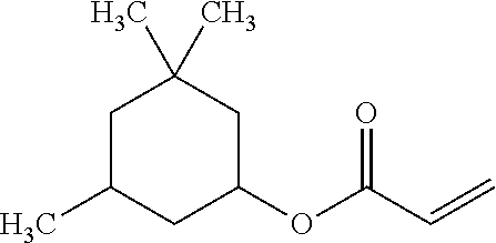
- ZMTBGVBNTHTBEC-UHFFFAOYSA-N C=CC(=O)OC1CC(C)CC(C)(C)C1 Chemical compound C=CC(=O)OC1CC(C)CC(C)(C)C1 ZMTBGVBNTHTBEC-UHFFFAOYSA-N 0.000 description 1
- DAKWPKUUDNSNPN-UHFFFAOYSA-N C=CC(=O)OCC(CC)(COC(=O)C=C)COC(=O)C=C Chemical compound C=CC(=O)OCC(CC)(COC(=O)C=C)COC(=O)C=C DAKWPKUUDNSNPN-UHFFFAOYSA-N 0.000 description 1
- WQYSWQUCKYYWKW-UHFFFAOYSA-N C=CC(=O)OCCCOCCC(COCCCOC(=O)C=C)(COCCOC(=O)C=C)COCCOC(=O)C=C Chemical compound C=CC(=O)OCCCOCCC(COCCCOC(=O)C=C)(COCCOC(=O)C=C)COCCOC(=O)C=C WQYSWQUCKYYWKW-UHFFFAOYSA-N 0.000 description 1
- KBQVDAIIQCXKPI-UHFFFAOYSA-N C=CC(=O)OCCC[Si](OC)(OC)OC Chemical compound C=CC(=O)OCCC[Si](OC)(OC)OC KBQVDAIIQCXKPI-UHFFFAOYSA-N 0.000 description 1
- RZVINYQDSSQUKO-UHFFFAOYSA-N C=CC(=O)OCCOC1=CC=CC=C1 Chemical compound C=CC(=O)OCCOC1=CC=CC=C1 RZVINYQDSSQUKO-UHFFFAOYSA-N 0.000 description 1
- FTALTLPZDVFJSS-UHFFFAOYSA-N C=CC(=O)OCCOCCOCC Chemical compound C=CC(=O)OCCOCCOCC FTALTLPZDVFJSS-UHFFFAOYSA-N 0.000 description 1
- HCLJOFJIQIJXHS-UHFFFAOYSA-N C=CC(=O)OCCOCCOCCOCCOC(=O)C=C Chemical compound C=CC(=O)OCCOCCOCCOCCOC(=O)C=C HCLJOFJIQIJXHS-UHFFFAOYSA-N 0.000 description 1
- XBCFXELSWDAYIW-UHFFFAOYSA-N C=CC(=O)OCOC1=CC=C(C(C)(C)C2=CC=C(OCOC(=O)C=C)C=C2)C=C1 Chemical compound C=CC(=O)OCOC1=CC=C(C(C)(C)C2=CC=C(OCOC(=O)C=C)C=C2)C=C1 XBCFXELSWDAYIW-UHFFFAOYSA-N 0.000 description 1
- LTQBNYCMVZQRSD-UHFFFAOYSA-N C=CC1=CC=C([Si](OC)(OC)OC)C=C1 Chemical compound C=CC1=CC=C([Si](OC)(OC)OC)C=C1 LTQBNYCMVZQRSD-UHFFFAOYSA-N 0.000 description 1
- YDMNUIPUMHFGNE-UHFFFAOYSA-N CC(C)(C)C1=CC=C(OCC2CC2)C=C1 Chemical compound CC(C)(C)C1=CC=C(OCC2CC2)C=C1 YDMNUIPUMHFGNE-UHFFFAOYSA-N 0.000 description 1
- XMLYCEVDHLAQEL-UHFFFAOYSA-N CC(C)(O)C(=O)C1=CC=CC=C1 Chemical compound CC(C)(O)C(=O)C1=CC=CC=C1 XMLYCEVDHLAQEL-UHFFFAOYSA-N 0.000 description 1
- KJRRQXYWFQKJIP-UHFFFAOYSA-N CC1=COC=C1 Chemical compound CC1=COC=C1 KJRRQXYWFQKJIP-UHFFFAOYSA-N 0.000 description 1
- PUMREIFKTMLCAF-UHFFFAOYSA-N CC1=COC=N1 Chemical compound CC1=COC=N1 PUMREIFKTMLCAF-UHFFFAOYSA-N 0.000 description 1
- UPTDGLUMDSQHIA-UHFFFAOYSA-N CCC(COC1CC(OC2CC(OC3CC(OC4CC(OC5CC(OC)CC(C6CO6)C5)CC(C5CO5)C4)CC(C4CO4)C3)CC(C3CO3)C2)CC(C2CO2)C1)(COC1CCCC(C2CC2)C1OC)COC1CCCC(C2CO2)C1OC1CCCC(C2CO2)C1OC1CCCC(C2CO2)C1OC1CCCC(C2CO2)C1OC1CCCC(C2CO2)C1OC Chemical compound CCC(COC1CC(OC2CC(OC3CC(OC4CC(OC5CC(OC)CC(C6CO6)C5)CC(C5CO5)C4)CC(C4CO4)C3)CC(C3CO3)C2)CC(C2CO2)C1)(COC1CCCC(C2CC2)C1OC)COC1CCCC(C2CO2)C1OC1CCCC(C2CO2)C1OC1CCCC(C2CO2)C1OC1CCCC(C2CO2)C1OC1CCCC(C2CO2)C1OC UPTDGLUMDSQHIA-UHFFFAOYSA-N 0.000 description 1
- QECCQGLIYMMHCR-UHFFFAOYSA-N CCC(COCC1CO1)(COCC1CO1)COCC1CO1 Chemical compound CCC(COCC1CO1)(COCC1CO1)COCC1CO1 QECCQGLIYMMHCR-UHFFFAOYSA-N 0.000 description 1
- SLDBAXYJAIRQMX-UHFFFAOYSA-N CCC1=CSC=C1 Chemical compound CCC1=CSC=C1 SLDBAXYJAIRQMX-UHFFFAOYSA-N 0.000 description 1
- ROSZGQWDLUNVKX-UHFFFAOYSA-N CCCCCCCCCCCCOCC1CC1 Chemical compound CCCCCCCCCCCCOCC1CC1 ROSZGQWDLUNVKX-UHFFFAOYSA-N 0.000 description 1
- JXUKBNICSRJFAP-UHFFFAOYSA-N CCO[Si](CCCOCC1CO1)(OCC)OCC Chemical compound CCO[Si](CCCOCC1CO1)(OCC)OCC JXUKBNICSRJFAP-UHFFFAOYSA-N 0.000 description 1
- AQLHWLRXOLFKKN-UHFFFAOYSA-N CO[Si](CCC1CCC2CC2C1)(OC)OC Chemical compound CO[Si](CCC1CCC2CC2C1)(OC)OC AQLHWLRXOLFKKN-UHFFFAOYSA-N 0.000 description 1
- QNODIIQQMGDSEF-UHFFFAOYSA-N O=C(C1=CC=CC=C1)C1(O)CCCCC1 Chemical compound O=C(C1=CC=CC=C1)C1(O)CCCCC1 QNODIIQQMGDSEF-UHFFFAOYSA-N 0.000 description 1
- RWCCWEUUXYIKHB-UHFFFAOYSA-N O=C(C1=CC=CC=C1)C1=CC=CC=C1 Chemical compound O=C(C1=CC=CC=C1)C1=CC=CC=C1 RWCCWEUUXYIKHB-UHFFFAOYSA-N 0.000 description 1
Images


Classifications
-
- C—CHEMISTRY; METALLURGY
- C08—ORGANIC MACROMOLECULAR COMPOUNDS; THEIR PREPARATION OR CHEMICAL WORKING-UP; COMPOSITIONS BASED THEREON
- C08G—MACROMOLECULAR COMPOUNDS OBTAINED OTHERWISE THAN BY REACTIONS ONLY INVOLVING UNSATURATED CARBON-TO-CARBON BONDS
- C08G61/00—Macromolecular compounds obtained by reactions forming a carbon-to-carbon link in the main chain of the macromolecule
- C08G61/12—Macromolecular compounds containing atoms other than carbon in the main chain of the macromolecule
-
- H—ELECTRICITY
- H01—ELECTRIC ELEMENTS
- H01G—CAPACITORS; CAPACITORS, RECTIFIERS, DETECTORS, SWITCHING DEVICES, LIGHT-SENSITIVE OR TEMPERATURE-SENSITIVE DEVICES OF THE ELECTROLYTIC TYPE
- H01G9/00—Electrolytic capacitors, rectifiers, detectors, switching devices, light-sensitive or temperature-sensitive devices; Processes of their manufacture
- H01G9/004—Details
- H01G9/022—Electrolytes; Absorbents
- H01G9/025—Solid electrolytes
- H01G9/028—Organic semiconducting electrolytes, e.g. TCNQ
-
- C—CHEMISTRY; METALLURGY
- C08—ORGANIC MACROMOLECULAR COMPOUNDS; THEIR PREPARATION OR CHEMICAL WORKING-UP; COMPOSITIONS BASED THEREON
- C08G—MACROMOLECULAR COMPOUNDS OBTAINED OTHERWISE THAN BY REACTIONS ONLY INVOLVING UNSATURATED CARBON-TO-CARBON BONDS
- C08G73/00—Macromolecular compounds obtained by reactions forming a linkage containing nitrogen with or without oxygen or carbon in the main chain of the macromolecule, not provided for in groups C08G12/00 - C08G71/00
-
- H—ELECTRICITY
- H01—ELECTRIC ELEMENTS
- H01G—CAPACITORS; CAPACITORS, RECTIFIERS, DETECTORS, SWITCHING DEVICES, LIGHT-SENSITIVE OR TEMPERATURE-SENSITIVE DEVICES OF THE ELECTROLYTIC TYPE
- H01G9/00—Electrolytic capacitors, rectifiers, detectors, switching devices, light-sensitive or temperature-sensitive devices; Processes of their manufacture
- H01G9/0029—Processes of manufacture
- H01G9/0036—Formation of the solid electrolyte layer
-
- H—ELECTRICITY
- H01—ELECTRIC ELEMENTS
- H01G—CAPACITORS; CAPACITORS, RECTIFIERS, DETECTORS, SWITCHING DEVICES, LIGHT-SENSITIVE OR TEMPERATURE-SENSITIVE DEVICES OF THE ELECTROLYTIC TYPE
- H01G9/00—Electrolytic capacitors, rectifiers, detectors, switching devices, light-sensitive or temperature-sensitive devices; Processes of their manufacture
- H01G9/004—Details
- H01G9/022—Electrolytes; Absorbents
- H01G9/025—Solid electrolytes
-
- H—ELECTRICITY
- H01—ELECTRIC ELEMENTS
- H01G—CAPACITORS; CAPACITORS, RECTIFIERS, DETECTORS, SWITCHING DEVICES, LIGHT-SENSITIVE OR TEMPERATURE-SENSITIVE DEVICES OF THE ELECTROLYTIC TYPE
- H01G9/00—Electrolytic capacitors, rectifiers, detectors, switching devices, light-sensitive or temperature-sensitive devices; Processes of their manufacture
- H01G9/15—Solid electrolytic capacitors
Definitions
- the present invention relates to an electrolyte material formulation, an electrolyte material composition formed from the electrolyte material formulation, and a solid capacitor using the electrolytic material composition.
- Capacitors are a type of electronic elements that are widely used in various electronic products. With advancement in technology development, electronic products are being developed in the direction of miniaturization and light weight, and the capacitors used in electronic products are required to be miniaturized and have a high capacitance and low impedance when being used at a high frequency.
- Capacitors may be classified into conventional liquid capacitors and newly developed solid capacitors.
- a liquid electrolyte is used as a charge transfer substance.
- the main components of the liquid electrolyte include a high-boiling point alcohol, an ionic liquid, boric acid, phosphoric acid, an organic carboxylic acid, an ammonium, a high-polarity organic solvent, and a small amount of water.
- the components not only serve as charge transfer substances, but also have the function of patching a dielectric layer of aluminum oxide on an aluminum foil.
- the electrolyte may react with the exposed aluminum metal and aluminum oxide is generated, thus achieving the patching function.
- the conventional aluminum liquid capacitor can meet the requirement of high capacitance at a low cost, as the electrolyte used is a liquid, it has the disadvantages of low conductivity and poor high temperature resistance; moreover, in the process of aluminum oxide generation, hydrogen is also generated, and if excessive hydrogen is accumulated in the capacitor, capacitor rupture can easily occur, which will damage the electronic product.
- a hydrogen absorbing agent may be added to the liquid electrolyte to reduce the risk of capacity rupture, the problem is not eliminated.
- a new generation of solid capacitor in which the liquid electrolyte is directly replaced by a solid electrolyte.
- the solid electrolyte is formed by a conductive polymer. Anions of an oxidant are blended in the structure of the polymer as a dopant and holes are formed, so that the polymer has conductivity.
- the conductive polymer Compared with the liquid electrolyte or a solid organic semiconductor complex salt such as tetracyanoquinodimethane (TCNQ) composite salt and inorganic semiconductor MnO 2 used in conventional electrolyte capacitor, the conductive polymer has a high conductivity and a suitable high high-temperature insulation property, so the conductive polymer has propelled the development of the trend of using solid electrolyte in current electrolytic capacitors.
- the solid capacitor In addition to having long service life that is 6 times longer than that of a common capacitor, the solid capacitor has improved stability and its capacitance is not easily influenced by an ambient temperature and humidity in use. Additionally, the solid capacitor has the advantage of a low ESR, a low capacitance variation rate, an excellent frequency response (high frequency resistance), a high temperature resistance, and a high current resistance, and the problem of leakage and plasma explosion is eliminated. Although conventional liquid capacitor has high capacitance, its application is limited due to a high ESR.
- Jesse S. Shaffer et al disclose a method of using a conductive polymer in an electrolyte of an electrolytic capacitor for the first time in U.S. Pat. No. 4,609,971.
- the method includes immersing an anode aluminum foil of a capacitor in a mixture solution formed by a conductive polymer polyaniline powder and a dopant LiClO 4 , and then removing a solvent on the aluminum foil. Due to its excessively high molecular weight, polyaniline cannot permeate into micropores of the anode foil, so the impregnation rate of the capacitor obtained through this method is poor, and the impedance is high.
- Gerhard Hellwig et al disclose a chemical oxidation polymerization method of using a conductive polymer as an electrolyte of a capacitor in U.S. Pat. No. 4,803,596.
- the method includes respectively immersing a capacitor anode foil in a solution of a conductive polymer monomer and an oxidant, and polymerizing the conductive polymer monomer at a suitable condition, in which the conductive polymer electrolyte is accumulated to a sufficient thickness through multiple immersions.
- the conductive polymer PEDOT has the advantages of a high heat resistance, a high conductivity, a high charge transfer velocity, being non-toxic, a long service life, and no occurrence of capacitor rupture when being applied in a capacitor.
- Most solid capacitor manufacturers use the two materials to manufacture aluminum or tantalum solid capacitor.
- PEDOT on the aluminum foil surface or pores that is polymerized by immersing the capacitor element in a mixture solution containing the monomer EDOT and iron (III) p-toluenesulfonate mostly has a powder structure with a lower polymerization degree, and the physical properties of the powder structure are poor, so the powder structure cannot be easily adhered on the aluminum foil surface or pores as it is more likely to fall off from the surface or pores, and a complete PEDOT polymer structure cannot be easily formed on the aluminum foil surface or pores. Therefore, the stability of the solid capacitor at a voltage of 16 V or higher is poor, resulting in that the solid capacitor cannot be used in the process of a voltage of 16 V or higher, or the yield of the process is low. Moreover, since the powder structure formed by the conductive polymer PEDOT cannot be easily adhered on the aluminum foil pores, when the problem of falling off occurs, the withstandable working voltage is limited.
- a capacitor element is directly immersed in a polymer solution containing a polymer PEDOT, and a complete PEDOT polymer structure is formed on an aluminum foil surface or pores, so that a solid capacitor is applicable in a working environment of a voltage of 50 V.
- the cost of the polymer PEDOT material is higher than that of the monomer EDOT; the polymer PEDOT material is difficult to store; and the process needs more time and is more difficult to control.
- the industry calls for the development of a solid capacitor that can withstand a higher voltage, such as 50 V or more, has good stability and is priced at a relatively low cost, so as to replace the liquid capacitor in 3C products that require high temperature resistance and high frequency resistance.
- an electrolyte material formulation which comprises:
- the present invention is further directed to an electrolytic material composition formed from the electrolytic material formulation of the present invention through polymerization.
- the present invention is yet further directed to a solid capacitor, which comprises:
- the electrolyte material composition according to the present invention exhibits a better structural stability, and the solid capacitor manufactured from the electrolyte material composition, with the advantages of easy construction, low cost, and good process stability, thereby has a high withstanding voltage (or called sparkling voltage) and a high capacitance and can be working at 25 V, 35 V, 50 V, 63 V, or a higher voltage.
- FIG. 1 shows a capacitor element according to an embodiment of the present invention.
- alkyl it means a straight or branched carbon chain radical.
- alkyl is a carbon chain radical having 1 to 20 carbons (C 1-20 ), 1 to 15 carbons (C 1-15 ), 1 to 10 carbons (C 1-10 ), or 1 to 6 carbons (C 1-6 ).
- alkyl include, but are not limited to, methyl, ethyl, propyl (including all the isomer forms), n-propyl, isopropyl, butyl (including all the isomer forms), n-butyl, isobutyl, tert-butyl, pentyl (including all the isomer forms), and hexyl (including all the isomer forms).
- alkylene it means an optionally substituted, divalent, straight or branched carbon chain radical.
- alkylene is a carbon chain radical having 1 to 4 carbons (C 1-4 ).
- alkylene include, but are not limited to, methylene, ethylene, propylene (including all the isomer forms), n-propylene, isopropylene, butylene (including all the isomer forms), n-butylene, isobutylene, and tert-butylene.
- alkoxy means an alkyl as described above that is attached with an oxygen atom.
- alkoxy include, but are not limited to methoxy, ethoxy, propoxy, n-propoxy, 2-propoxy, n-butoxy, iso-butoxy, tert-butoxy, cyclohexyloxy, phenoxy, benzyloxy, and 2-naphthoxy.
- aryl it means mono-cyclic or multi-cyclic, monovalent aromatic radical.
- an aryl has 6 to 20 (C 6-20 ), 6 to 15 (C 6-15 ), or 6 to 10 (C 6-10 ) ring atoms.
- Examples of aryl include, but are not limited to, phenyl, naphthyl, fluorenyl, azulenyl, anthracyl, phenanthryl, pyrenyl, biphenyl, and terphenyl.
- bicyclic or tricyclic carbon ring one of whose rings is an aromatic ring and the other one or two rings can be saturated, partially unsaturated, or aromatic rings, such as dihydronaphthyl, indenyl, dihydroindenyl, and tetrahydronaphthyl.
- the present invention pertains to an electrolyte material formulation comprising (a) a monomer of formula (I), (b) a monomer of formula (II), and (c) a polymerizable compound.
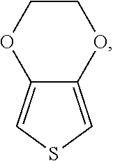
- the monomer (a) used in the present invention has the structure of the following formula (I):
- A is a C 1-4 alkylene substituted by (Rx) p and X is O or S, where Rx are independently H, unsubstituted or substituted C 1-20 alkyl or alkoxy, or unsubstituted or substituted C 6-20 aryl, and p is an integer from 0 to 2.
- the monomer (a) preferably includes, but is not limited to
- R4 and R5 each independently represent H, unsubstituted or substituted C 1-15 alkyl or alkoxy, or unsubstituted or substituted C 6-15 aryl.
- R4 and R5 each independently represent H or C 1-3 alkyl or alkoxy.
- the monomer (a) is N-(2-aminoethyl)-2-aminoethyl-N-(2-aminoethyl)-2-aminoethyl-N-(2-aminoethyl)-2-aminoethyl-N-(2-aminoethyl)-2-aminoethyl-N-(2-aminoethyl)-2-aminoethyl
- the electrolyte material formulation of the present invention comprises a monomer (b), thereby forming a highly polymerized conductive polymeric structure with the monomer (a).
- the monomer (b) has the structure of the following formula (II):
- the monomer (b) preferably includes, but is not limited to,
- R1, R2, and R3 each independently represent H or C 1-3 alkyl or alkoxy.
- the monomer (b) is N-(2-aminoethyl)-2-aminoethyl-N-(2-aminoethyl)-2-aminoethyl-N-(2-aminoethyl)-2-aminoethyl-N-(2-aminoethyl)-2-aminoethyl-N-(2-aminoethyl)-2-aminoethyl-N-(2-aminoethyl)-2-aminoethyl-N-(2-aminoethyl)-2-aminoethyl-N-(2-aminoethyl)-2-aminoethyl-N-(2-aminoethyl)-2-aminoethyl-N-(2-aminoethyl)-2-aminoethyl-N-(2-aminoethyl)-2-aminoethyl
- the electrolyte material formulation of the present invention comprises a polymerizable compound (c), thereby forming a second polymer to allow the highly polymerized first polymer polymerized from the monomer (a) and the monomer (b) to be easily adhered on the aluminum foil surface or pores without falling off from the surface or pores.
- the polymerizable compound (c) used in the present invention is present in the inventive electrolyte material formulation in the form of a monomer, an oligomer, or a combination thereof.
- the polymerizable compound used in the electrolytic material formulation of the present invention may be an epoxy group-containing polymerizable compound, vinyl-containing unsaturated polymerizable compound, acrylate-containing unsaturated polymerizable compound, or a mixture thereof.
- the polymerizable compound (c) is selected from the group consisting of:
- n is an integer greater than or equal to 3
- m is an integer greater than or equal to 2
- G is an organic group, an inorganic group, or a mixture thereof.
- the polymerizable compound is selected from the group consisting of:
- the polymerizable compound (c) has a molecular weight preferably ranging from 40 to 1,000,000, more preferably ranging from 40 to 500,000, and most preferably ranging from 40 to 100,000.
- the monomer (b) is in an amount of about 1 part by weight to about 800 parts by weight and the polymerizable compound (c) is in an amount of about 1 part by weight to about 10000 parts by weight based on 100 parts by weight of the monomer (a).
- the amount of the monomer (b) is about 5 parts by weight to about 400 parts by weight, and the amount of the polymerizable compound (c) is about 5 parts by weight to about 5000 parts by weight.
- the electrolyte material formulation according to the present invention may optionally contain an oxidant, which promotes the formation of the conductive polymer from the monomer (a) and the monomer (b).
- the oxidants useful in the present invention are known in the art, and can be, for example, alkali metal persulfates, ammonium salts, peroxides, or ferric salts of organic acids, or the combination thereof.
- the oxidant can be iron (III) p-toluenesulphonate, ammonium sulfate, ammonium persulfate, ammonium oxalate, ammonium perchlorate, or hydrogen peroxide or the mixtures thereof.
- the oxidant is iron (III) p-toluenesulfonate.
- the amount of the oxidant is preferably about 5 parts by weight to about 3000 parts by weight, more preferably about 100 parts by weight to about 1000 parts by weight, and most preferably about 100 parts by weight to about 300 parts by weight.
- the electrolyte material formulation of the present invention can optionally comprise a curing agent.
- a curing agent is added, and upon crosslinking and curing, a three-dimensional network structure is formed.
- the curing agent useful in the present invention is known in the art, and for example, can be an amine or an acid anhydride, such as,
- the weight ratio of the amount of the curing agent to that of the polymerizable compound (c) is 0 to 2, preferably 0 to 1.5.
- the electrolyte material formulation of the present invention may further comprise a catalyst.
- the catalyst useful in the present invention is known in the art, which for example, can be a tertiary amine, an azo compound, or a benzoyl compound.
- the useful catalyst includes:
- the catalyst is used in an amount such that a weight ratio of the catalyst to that of the polymerizable compound (c) is 0.001 to 1, preferably 0.005 to 0.5, and more preferably 0.01 to 0.25.
- the present invention also provides an electrolyte material composition formed from the electrolyte material formulation through polymerization, which comprises:
- the conductive polymer used in conventional solid electrolyte is normally in a lowly polymerized powder-like structure, which is not easy to be adhered on an anode foil surface or pores but likely to fall off from the surface or pores, exhibits a poor stability, and the production yield is low.
- the electrolyte material composition of the present invention contains a first polymer and a second polymer, and the first polymer and the second polymer do not react with each other.
- the first polymer is used as a conductive polymer and exhibits the characteristics of high heat resistance, high conductivity, high charge transfer velocity, being non-toxic, a long service life, and no occurrence of capacitor rupture when being applied in a capacitor.
- the first polymer is formed from the polymerization of the monomer (a) and the monomer (b) in the presence of an oxidant.
- the first polymer has a molecular weight ranging from 1000 to 500000, preferably ranging from 1000 to 50000, and more preferably ranging from 1000 to 20000.
- the second polymer is used as a polymerizable material, and in order to increase the degree of crosslinking of molecules in polymerization and enable the second polymer to be cured, the second polymer is optionally formed from the polymerization units derived from a polymerizable compound and a curing agent.
- the network structure of the second polymer will form a thin film to improve the stability of molecular structure of the first polymer, so that the first polymer can be adhered onto a capacitor element without falling off, and is applicable in a high-voltage (a voltage of 16 V or higher) working environment, preferably a working environment of a voltage of 63 V or higher.
- the electrolyte material formulation of the present invention is polymerized in a capacitor, and the process pertains to an in situ reaction.
- the in situ process may be classified into a one-solution method, a two-solution method, and a multiple-solution method.
- the electrolyte material formulation of the present invention and an oxidant can be formulated into a single solution, or formulated into two solutions including a first solution and a second solution, where the first solution contains the monomer (a), the monomer (b), and the polymerizable compound (c), and the second solution contains the oxidant.
- the electrolyte material formulation of the present invention can also be formulated into multiple solutions including a first solution, a second solution, and a third solution, where the first solution contains the monomer (a) and the monomer (b), the second solution contains the oxidant, and the third solution contains the polymerizable compound (c).
- a curing agent and a catalyst may be optionally added, where the curing agent and the catalyst are as defined above.
- the electrolyte material formulation of the present invention may further contain a solvent.
- the solvent useful in the present invention is not particularly limited in principle, which for example, can be water, alcohols, or benzenes, or combinations thereof, preferably methanol, ethanol, propanol, n-butanol, tert-butanol, or water, or combinations thereof.
- the present invention further provides a solid capacitor, comprising: an anode; a dielectric layer formed on the anode; a cathode; and a solid electrolyte located between the dielectric layer and the cathode, wherein the solid electrolyte comprises the electrolyte material composition mentioned above.
- the solid capacitor may be an aluminum solid capacitor, a tantalum solid capacitor, or a niobium solid capacitor.
- the anode is formed by, with an etched conductive metal foil as an anode foil, performing anode oxidation processing on a surface of the anode foil and introducing a wire from the anode foil
- the cathode is formed by, with another metal foil as a cathode foil, introducing a wire from the cathode foil.
- the dielectric layer is formed from an oxide or the like and is formed on the surface of the anode foil, and is located between the anode foil and the cathode foil.
- the anode foil and the cathode foil are formed from aluminum, tantalum, niobium, aluminum oxide, tantalum oxide, niobium oxide, titanium plated aluminum, or carbon plated aluminum.
- the anode foil and the cathode foil are wound into a cylinder, and immersed in the electrolyte material formulation and oxidant in the form of a solution, and after curing treatment (for example, thermal curing or photo curing), a solid electrolyte is formed between the dielectric layer and the cathode foil of the solid capacitor.
- a solid capacitor may be formed by using conventional technologies and materials.
- the capacitor element may be installed in a box with a bottom, and a seal element with an opening for exposing the wires may be disposed at the top of the box, and a solid capacitor may be formed after being sealed.
- the solid capacitor manufactured from the electrolyte material formulation of the present invention exhibits the advantages of easy construction, low cost, high voltage resistance (63 V or higher), high capacitance, and low impedance (35 m ⁇ or lower).
- FIG. 1 shows a capacitor element according to an embodiment of the present invention.
- an anode foil 1 and a cathode foil 3 and spacer components 5 a and 5 b that are inserted between the anode foil 1 and the cathode foil 3 are wound together to form a capacitor element 9 .
- Wires 7 a and 7 b serve as terminals for connecting the cathode foil 3 and the anode foil 1 to an external circuit.
- the number of wires connected to the cathode foil and the anode foil is not particularly limited, provided that the cathode foil and the anode foil both are wire connected.
- the number of the cathode foils and the anode foils is not particularly limited, and for example, the number of the cathode foils may be the same as that of the anode foils, or the number of the cathode foils may be greater than that of the anode foils.
- the dielectric layer (not shown) formed from an oxide or the like is formed on the surface of the anode foil, and is located between the anode foil and the cathode foil.
- the anode foil 1 , the cathode foil 3 , the spacer components 5 a and 5 b , and the wires 7 a and 7 b are manufactured by using known materials through known technologies.
- the capacitor element is immersed in the electrolyte material formulation in the form of a solution so that a solid electrolyte is formed between the dielectric layer and the cathode foil of the solid capacitor.
- the method for forming the solid electrolyte includes, first, as described above, formulating the electrolytic material formulation and an oxidant into a single solution or multiple solutions. If the electrolytic material formulation and the oxidant is formulated into a single solution, the capacitor element 9 is directly immersed in the solution of the electrolytic material formulation and the oxidant; and if the electrolyte material formulation and the oxidant is formulated into two solutions as mentioned above, the capacitor element 9 can be first immersed in the first solution and then immersed in the second solution, or the capacitor element 9 can be first immersed in the second solution and then immersed in the first solution, and thereafter performing polymerization reaction.
- the polymerization reaction can be performed at a temperature of 25° C. to 260° C., preferably of 85° C.
- the monomer (a) first reacts with monomer (b) in the presence of the oxidant to form a conductive polymer.
- the polymerizable compound is subjected to curing treatment (for example, heat treatment) to form a polymerizable material, and optionally, a curing agent, or catalyst, or a mixture thereof is added in the heat treatment process.
- an electrolyte material composition containing the conductive polymer and the polymerizable material is formed between the dielectric layer of the anode foil and the cathode foil.
- the electrolyte material composition containing the conductive polymer and the polymerizable material is formed from the electrolyte material formulation of the present invention upon heat treatment.
- the polymerizable material can enhance the stability of the structure of the conductive polymer and prevent the anode from being stricken through by leakage current, thereby avoiding short circuit of the solid capacitor. Therefore, the polymerizable material can improve the voltage resistance of the solid capacitor, and can improve the adhesion property of the conductive polymer, so a highly polymerized structure of the conductive polymer can be formed on an electrode surface or pores of the metal foil, and can withstand a higher voltage and has a higher capacitance.
- the solid capacitor can be widely used in industries requiring high-voltage capacitors, for example, drive power supplies for LED lamps, electronic energy-saving lamps and rectifiers, motor electronic devices, computer motherboards, frequency converters, network communications, power supplies for medical devices, and other high-end areas including UPS.
- drive power supplies for LED lamps for example, drive power supplies for LED lamps, electronic energy-saving lamps and rectifiers, motor electronic devices, computer motherboards, frequency converters, network communications, power supplies for medical devices, and other high-end areas including UPS.
- a capacitor element 9 was immersed in an electrolyte material formulation formed by mixing 30 g
- the capacitor element was taken out from the electrolyte material formulation, and subjected to heat polymerization at a temperature in the range of 25° C. to 260° C., so as to form a solid electrolyte containing a mixture of a conductive polymer and a polymerizable material.
- a capacitor element 9 was first immersed in a first solution formed by mixing 30 g
- the capacitor element was taken out from the electrolytic material formulation, and subjected to heat polymerization at a temperature in the range of 25° C. to 260° C., so as to form a solid electrolyte containing a mixture of a conductive polymer and a polymerizable material.
- a capacitor element 9 was first immersed in a second solution of 100 g tert-butanol solution containing 50% iron (III) p-toluenesulphonate for 5 min, and then immersed in a first solution formed by mixing 7.9 g
- the capacitor element was taken from the electrolytic material formulation, and subjected to heat polymerization at a temperature in the range of 25° C. to 260° C., so as to form a solid electrolyte containing a mixture of a conductive polymer and a polymerizable material.
- a capacitor element 9 was first immersed in a first solution containing 30 g
- the capacitor element was taken from the electrolytic material formulation, and subjected to heat polymerization at a temperature in the range of 25° C. to 260° C., so as to form a solid electrolyte containing a mixture of a conductive polymer and a polymerizable material.
- a capacitor element 9 was first immersed in a second solution formed by mixing 100 g ethanol solution containing 55% iron (III) p-toluenesulphonate, 20 g polymerizable compound
- the capacitor element was taken from the electrolytic material formulation, and subjected to heat polymerization at a temperature in the range of 25° C. to 260° C., so as to form a solid electrolyte containing a mixture of a conductive polymer and a polymerizable material.
- a capacitor element 9 was immersed in an electrolyte material formulation formed by mixing 40 g
- the capacitor element was taken from the electrolytic material formulation, and subjected to heat polymerization at a temperature in the range of 25° C. to 260° C., so as to form a solid electrolyte containing a mixture of polymers of a conductive polymer and a polymerizable material.
- a capacitor element 9 was immersed in an electrolyte material formulation formed by mixing 30 g
- the capacitor element was taken from the electrolytic material formulation, and subjected to heat polymerization at a temperature in the range of 25° C. to 260° C., so as to form a solid electrolyte containing a mixture of a conductive polymer and a polymerizable material.
- a capacitor element 9 was first immersed in a first solution formed by mixing 7.9 g 95% ethanol diluted
- the capacitor element was taken from the electrolytic material formulation, and subjected to heat polymerization at a temperature in the range of 25° C. to 260° C., so as to form a solid electrolyte containing a mixture of a conductive polymer and a polymerizable material.
- a capacitor element 9 was immersed in an electrolyte material formulation formed by mixing 30 g
- the capacitor element was taken from the electrolytic material formulation, and subjected to heat polymerization at a temperature in the range of 25° C. to 260° C., so as to form a solid electrolyte containing a mixture of a conductive polymer and a polymerizable material.
- a capacitor element 9 was immersed in an electrolyte material formulation formed by mixing 7.9 g
- the capacitor element was taken from the electrolytic material formulation, and subjected to heat polymerization at a temperature in the range of 25° C. to 260° C. so as to form a solid electrolyte containing a mixture of a conductive polymer and a polymerizable material.
- a capacitor element 9 was first immersed in a first solution formed by mixing 30 g
- the capacitor element was taken from the electrolytic material formulation, and subjected to heat polymerization at a temperature in the range of 25° C. to 260° C., so as to form a solid electrolyte containing a mixture of a conductive polymer and a polymerizable material.
- the capacitor element 9 was first immersed in a second solution of 100 g tert-butanol solution containing 40% iron (III) p-toluenesulphonate for 5 min, and then immersed in a first solution formed by mixing 30 g
- the capacitor element was taken from the electrolytic material formulation, and subjected to heat polymerization at a temperature in the range of 25° C. to 260° C., so as to form a solid electrolyte containing a mixture of a conductive polymer and a polymerizable material.
- a capacitor element 9 was first immersed in a first solution containing 30 g
- the capacitor element was taken from the electrolytic material formulation, and subjected to heat polymerization at a temperature in the range of 25° C. to 260° C., so as to form a solid electrolyte containing a mixture of a conductive polymer and a polymerizable material.
- a capacitor element 9 was first immersed in a second solution formed by mixing 100 g tert-butanol solution containing 40% iron (III) p-toluenesulphonate and 30 g polymerizable compound
- the capacitor element was taken from the electrolytic material formulation, and subjected to heat polymerization at a temperature in the range of 25° C. to 260° C., so as to form a solid electrolyte containing a mixture of a conductive polymer and a polymerizable material.
- a capacitor element 9 was immersed in an electrolyte material formulation formed by mixing 50 g
- the capacitor element was taken from the electrolytic material formulation, and subjected to heat polymerization at a temperature in the range of 25° C. to 260° C., so as to form a solid electrolyte containing a mixture of a conductive polymer and a polymerizable material.
- a capacitor element 9 shown in FIG. 1 was immersed in an electrolyte material formulation formed by mixing 10 g
- the capacitor elements having the solid electrolytes prepared according to Examples 1 to 25 and Comparative Example 1 were disposed in boxes with a bottom, and the boxes were sealed with a seal element formed by an elastic substance with wires exposed, thus forming solid capacitors.
- the solid capacitors were tested by HP4284A LCR meter at a temperature of 20° C. and a frequency of 120 Hz.
Landscapes
- Engineering & Computer Science (AREA)
- Power Engineering (AREA)
- Chemical & Material Sciences (AREA)
- Chemical Kinetics & Catalysis (AREA)
- Electrochemistry (AREA)
- Microelectronics & Electronic Packaging (AREA)
- Manufacturing & Machinery (AREA)
- Health & Medical Sciences (AREA)
- Medicinal Chemistry (AREA)
- Polymers & Plastics (AREA)
- Organic Chemistry (AREA)
- Polyoxymethylene Polymers And Polymers With Carbon-To-Carbon Bonds (AREA)
- Conductive Materials (AREA)
- Compositions Of Macromolecular Compounds (AREA)
- Epoxy Resins (AREA)
Abstract
-
- (a) a monomer of formula (I)

-
- (b) a monomer of formula (II)

-
- and
- (c) a polymerizable compound,
- wherein A, X, B1, B2, R1 to R3, q and w are defined as those recited in the specification, and the monomer (b) is in an amount of about 1 part by weight to about 800 parts by weight and the polymerizable compound (c) is in an amount of about 1 part by weight to about 10000 parts by weight based on 100 parts by weight of the monomer (a). The present invention further provides an electrolytic material composition obtained by the polymerization of the aforementioned electrolytic material formulation. The electrolytic material composition can be applied to a solid electrolyte capacitor.
Description
-
- (a) a monomer of formula (I):

-
- (b) a monomer of formula (II):

-
- and
- (c) a polymerizable compound,
- wherein:
- A is a C1-4 alkylene substituted by (Rx)p:
- X is O or S;
- B1 is O, S, or N;
- B2 is N or C;
- R1, R2, R3 and Rx are independently H, unsubstituted or substituted C1-20 alkyl or alkoxy, or unsubstituted or substituted C6-20 aryl;
- p is an integer from 0 to 2; and
- q and w are independently an integer of 0 or 1, and
- wherein the monomer (b) is in an amount of about 1 part by weight to about 800 parts by weight and the polymerizable compound (c) is in an amount of about 1 part by weight to about 10000 parts by weight based on 100 parts by weight of the monomer (a).
-
- an anode;
- a dielectric layer formed on the anode;
- a cathode; and
- a solid electrolyte located between the dielectric layer and the cathode, in which the solid electrolyte comprises the electrolyte material composition according to the present invention.

wherein A is a C1-4alkylene substituted by (Rx)p and X is O or S, where Rx are independently H, unsubstituted or substituted C1-20 alkyl or alkoxy, or unsubstituted or substituted C6-20 aryl, and p is an integer from 0 to 2.

wherein R4 and R5 each independently represent H, unsubstituted or substituted C1-15 alkyl or alkoxy, or unsubstituted or substituted C6-15 aryl. Preferably, R4 and R5 each independently represent H or C1-3alkyl or alkoxy.

(EDOT),

(3-methyl-3,4-dihydro-2H-thieno[3,4-b][1,4]dioxepine), or
(thieno [3,4-d][1,3]dioxole).

wherein, B1 is O, S or N; B2 is N or C; q and w each independently represent an integer of 0 or 1; R1, R2 and R3 each independently represent H, unsubstituted or substituted C1-20 alkyl or alkoxy, or unsubstituted or substituted C6-20 aryl, when B1 being O or S, q being 0; and when B2 being N, w being 0.

or a combination thereof, wherein R1, R2, and R3 each independently represent H or C1-3alkyl or alkoxy.


where n is an integer greater than or equal to 3, m is an integer greater than or equal to 2, and G is an organic group, an inorganic group, or a mixture thereof.


-
- (A) a first polymer, formed from the polymerization units derived from the monomer (a) and the monomer (b); and
- (B) a second polymer, formed from the polymerization units derived from the polymerizable compound (c).

2.6 g

100 g ethanol solution containing 40% iron (III) p-toluenesulphonate, 20 g polymerizable compound
20 g curing agent
and 2 g catalyst
for 5 min. Then, the capacitor element was taken out from the electrolyte material formulation, and subjected to heat polymerization at a temperature in the range of 25° C. to 260° C., so as to form a solid electrolyte containing a mixture of a conductive polymer and a polymerizable material.

5.3 g

15 g polymerizable compound

20 g curing agent
and 2 g catalyst

for 5 min, and then immersed in a second solution of 100 g n-butanol solution containing 45% iron (III) p-toluenesulfonate for 5 min. Then, the capacitor element was taken out from the electrolytic material formulation, and subjected to heat polymerization at a temperature in the range of 25° C. to 260° C., so as to form a solid electrolyte containing a mixture of a conductive polymer and a polymerizable material.

30 g

15 g polymerizable compound
15 g curing agent

and 2 g catalyst

for 5 min. Then, the capacitor element was taken from the electrolytic material formulation, and subjected to heat polymerization at a temperature in the range of 25° C. to 260° C., so as to form a solid electrolyte containing a mixture of a conductive polymer and a polymerizable material.

and 2.6 g
for 5 min, and then immersed in a second solution formed by mixing 100 g tert-butanol solution containing 50% iron (III) p-toluenesulfonate, 20 g polymerizable compound
20 g curing agent
and 2 g catalyst

for 5 min. The capacitor element was taken from the electrolytic material formulation, and subjected to heat polymerization at a temperature in the range of 25° C. to 260° C., so as to form a solid electrolyte containing a mixture of a conductive polymer and a polymerizable material.

20 g curing agent

and 2 g catalyst

for 5 min, and then immersed in a first solution containing 30 g
and 5.3 g
for 5 min. Then, the capacitor element was taken from the electrolytic material formulation, and subjected to heat polymerization at a temperature in the range of 25° C. to 260° C., so as to form a solid electrolyte containing a mixture of a conductive polymer and a polymerizable material.

5.3 g
120 g propanol solution containing 40% iron (III) p-toluenesulfonate, 50 g polymerizable compound

50 g curing agent
and 5 g catalyst

for 5 min. Then, the capacitor element was taken from the electrolytic material formulation, and subjected to heat polymerization at a temperature in the range of 25° C. to 260° C., so as to form a solid electrolyte containing a mixture of a conductive polymer and a polymerizable material.

2.6 g
120 g ethanol solution containing 40% iron (III) p-toluenesulphonate, 40 g polymerizable compound

40 g curing agent

and 5 g catalyst

for 5 min. Then, the capacitor element was taken from the electrolytic material formulation, and subjected to heat polymerization at a temperature in the range of 25° C. to 260° C., so as to form a solid electrolyte containing a mixture of polymers of a conductive polymer and a polymerizable material.

5.3 g
100 g tert-butanol solution containing 40% iron (III) p-toluenesulfonate, 20 g polymerizable compound

and 20 g curing agent
for 5 min. Then, the capacitor element was taken from the electrolytic material formulation, and subjected to heat polymerization at a temperature in the range of 25° C. to 260° C., so as to form a solid electrolyte containing a mixture of a conductive polymer and a polymerizable material.

30 g
15 g polymerizable compound

15 g curing agent
and 2 g catalyst

for 5 min, and then immersed in a second solution of 100 g n-butanol solution containing 45% iron (III) p-toluenesulphonate for 5 min. Then, the capacitor element was taken from the electrolytic material formulation, and subjected to heat polymerization at a temperature in the range of 25° C. to 260° C., so as to form a solid electrolyte containing a mixture of a conductive polymer and a polymerizable material.

2.6 g
150 g tert-butanol solution containing 40% iron (III) p-toluenesulfonate, 20 g polymerizable compound

20 g curing agent
and 2 g catalyst

for 5 min. Then, the capacitor element was taken from the electrolytic material formulation, and subjected to heat polymerization at a temperature in the range of 25° C. to 260° C., so as to form a solid electrolyte containing a mixture of a conductive polymer and a polymerizable material.

5.3 g
150 g tert-butanol solution containing 40% iron (III) p-toluenesulfonate, 20 g polymerizable compound

20 g curing agent
and 2 g catalyst

for 5 min. Then, the capacitor element was taken from the electrolytic material formulation, and subjected to heat polymerization at a temperature in the range of 25° C. to 260° C., so as to form a solid electrolyte containing a mixture of a conductive polymer and a polymerizable material.
7.9 g
150 g tert-butanol solution containing 40% iron (III) p-toluenesulfonate, 20 g polymerizable compound

15 g curing agent

and 2 g catalyst

for 5 min. Then, the capacitor element was taken from the electrolytic material formulation, and subjected to heat polymerization at a temperature in the range of 25° C. to 260° C., so as to form a solid electrolyte containing a mixture of a conductive polymer and a polymerizable material.

2.6 g
150 g tert-butanol solution containing 40% iron (III) p-toluenesulfonate, 20 g polymerizable compound

15 g curing agent

and 2 g catalyst

for 5 min. Then, the capacitor element was taken from the electrolytic material formulation, and subjected to heat polymerization at a temperature in the range of 25° C. to 260° C., so as to form a solid electrolyte containing a mixture of a conductive polymer and a polymerizable material.

5.3 g
150 g tert-butanol solution containing 40% iron (III) p-toluenesulfonate, 20 g polymerizable compound

40 g curing agent

and 5 g catalyst

for 5 min. Then, the capacitor element was taken from the electrolytic material formulation, and subjected to heat polymerization at a temperature in the range of 25° C. to 260° C., so as to form a solid electrolyte containing a mixture of a conductive polymer and a polymerizable material.

30 g
100 g tert-butanol solution containing 40% iron (III) p-toluenesulfonate, 30 g polymerizable compound

40 g curing agent

and 3 g catalyst

for 5 min. Then, the capacitor element was taken from the electrolytic material formulation, and subjected to heat polymerization at a temperature in the range of 25° C. to 260° C. so as to form a solid electrolyte containing a mixture of a conductive polymer and a polymerizable material.

2.6 g
30 g polymerizable compound

and 3 g catalyst

for 5 min, and then immersed in a second solution of a 100 g tert-butanol solution containing 50% iron (III) p-toluenesulfonate for 5 min. Then, the capacitor element was taken from the electrolytic material formulation, and subjected to heat polymerization at a temperature in the range of 25° C. to 260° C., so as to form a solid electrolyte containing a mixture of a conductive polymer and a polymerizable material.
5.3 g
and 30 g polymerizable compound
for 5 min. Then, the capacitor element was taken from the electrolytic material formulation, and subjected to heat polymerization at a temperature in the range of 25° C. to 260° C., so as to form a solid electrolyte containing a mixture of a conductive polymer and a polymerizable material.

and 7.9 g
for 5 min, and then immersed in a second solution formed by mixing 100 g tert-butanol solution containing 40% iron (III) p-toluenesulfonate, 25 g polymerizable compound
and 3 g catalyst

for 5 min. Then, the capacitor element was taken from the electrolytic material formulation, and subjected to heat polymerization at a temperature in the range of 25° C. to 260° C., so as to form a solid electrolyte containing a mixture of a conductive polymer and a polymerizable material.

for 5 min, and then immersed in a first solution containing 2.6 g
and 30 g

for 5 min. Then, the capacitor element was taken from the electrolytic material formulation, and subjected to heat polymerization at a temperature in the range of 25° C. to 260° C., so as to form a solid electrolyte containing a mixture of a conductive polymer and a polymerizable material.
5.3 g

150 g tert-butanol solution containing 40% iron (III) p-toluenesulfonate, 30 g polymerizable compound

and 3 g catalyst

for 5 min. Then, the capacitor element was taken from the electrolytic material formulation, and subjected to heat polymerization at a temperature in the range of 25° C. to 260° C., so as to form a solid electrolyte containing a mixture of a conductive polymer and a polymerizable material.

7.9 g

150 g tert-butanol solution containing 40% iron (III) p-toluenesulfonate, 30 g polymerizable compound

and 3 g catalyst
for 5 min. Then, the capacitor element was taken from the electrolytic material formulation, and subjected to heat polymerization at a temperature in the range of 25° C. to 260° C., so as to form a solid electrolyte containing a mixture of a conductive polymer and a polymerizable material.

7.9 g

150 g tert-butanol solution containing 40% iron (I) p-toluenesulfonate, 30 g polymerizable compound

and 3 g catalyst

for 5 min. Then, the capacitor element was taken from the electrolytic material formulation, and subjected to heat polymerization at a temperature in the range of 25° C. to 260° C., so as to form a solid electrolyte containing a mixture of a conductive polymer and a polymerizable material.
7.9 g

150 g tert-butanol solution containing 40% iron (III) p-toluenesulfonate, 30 g polymerizable compound

and 3 g catalyst
for 5 min. Then, the capacitor element was taken from the electrolytic material formulation, and subjected to heat polymerization at a temperature in the range of 25° C. to 260° C., so as to form a solid electrolyte containing a mixture of a conductive polymer and a polymerizable material.

7.9 g

150 g tert-butanol solution containing 40% iron (III) p-toluenesulfonate, 30 g polymerizable compound

and 3 g catalyst

for 5 min. Then, the capacitor element was taken from the electrolytic material formulation, and subjected to heat polymerization at a temperature in the range of 25° C. to 260° C., so as to form a solid electrolyte containing a mixture of a conductive polymer and a polymerizable material.

7.9 g

150 g tert-butanol solution containing 40% iron (I) p-toluenesulfonate, 30 g polymerizable compound

and 3 g catalyst

for 5 min. Then, the capacitor element was taken from the electrolytic material formulation, and subjected to heat polymerization at a temperature in the range of 25° C. to 260° C., so as to form a solid electrolyte containing a mixture of a conductive polymer and a polymerizable material.

and 100 g tert-butanol solution containing 40% iron (III) p-toluenesulphonate for 5 min. Then, the capacitor element was taken from the electrolytic material formulation, and subjected to heat polymerization at a temperature in the range of 25° C. to 260° C., to form a solid electrolyte.
Preparation of Solid Capacitor and Electrical Property Test
| TABLE 1 | |||
| Capacitance for | |||
| Storage (CS) | Withstand | ||
| (μF, 120 Hz) | Voltage | ||
| Example 1 | 104 | 66 | ||
| Example 2 | 103 | 79 | ||
| Example 3 | 98 | 87 | ||
| Example 4 | 97 | 67 | ||
| Example 5 | 96 | 71 | ||
| Example 6 | 95 | 72 | ||
| Example 7 | 103 | 70 | ||
| Example 8 | 108 | 71 | ||
| Example 9 | 105 | 90 | ||
| Example 10 | 106 | 74 | ||
| Example 11 | 103 | 76 | ||
| Example 12 | 104 | 84 | ||
| Example 13 | 98 | 72 | ||
| Example 14 | 103 | 79 | ||
| Example 15 | 100 | 83 | ||
| Example 16 | 100 | 66 | ||
| Example 17 | 97 | 81 | ||
| Example 18 | 99 | 91 | ||
| Example 19 | 107 | 79 | ||
| Example 20 | 101 | 81 | ||
| Example 21 | 105 | 84 | ||
| Example 22 | 98 | 82 | ||
| Example 23 | 102 | 81 | ||
| Example 24 | 97 | 86 | ||
| Example 25 | 104 | 84 | ||
| Comparative | 92 | 51 | ||
| Example 1 | ||||
Claims (6)


Priority Applications (1)
| Application Number | Priority Date | Filing Date | Title |
|---|---|---|---|
| US15/135,720 US9947480B2 (en) | 2011-12-30 | 2016-04-22 | Electrolyte material formulation, electrolyte material composition formed therefrom and use thereof |
Applications Claiming Priority (5)
| Application Number | Priority Date | Filing Date | Title |
|---|---|---|---|
| TW100150078A | 2011-12-30 | ||
| TW100150078A TWI460203B (en) | 2011-12-30 | 2011-12-30 | Electrolyte material formulation, electrolyte material composition formed therefrom and use thereof |
| TW100150078 | 2011-12-30 | ||
| US13/717,984 US9691551B2 (en) | 2011-12-30 | 2012-12-18 | Electrolyte material formulation, electrolyte material composition formed therefrom and use thereof |
| US15/135,720 US9947480B2 (en) | 2011-12-30 | 2016-04-22 | Electrolyte material formulation, electrolyte material composition formed therefrom and use thereof |
Related Parent Applications (1)
| Application Number | Title | Priority Date | Filing Date |
|---|---|---|---|
| US13/717,984 Division US9691551B2 (en) | 2011-12-30 | 2012-12-18 | Electrolyte material formulation, electrolyte material composition formed therefrom and use thereof |
Publications (2)
| Publication Number | Publication Date |
|---|---|
| US20160240321A1 US20160240321A1 (en) | 2016-08-18 |
| US9947480B2 true US9947480B2 (en) | 2018-04-17 |
Family
ID=47031191
Family Applications (2)
| Application Number | Title | Priority Date | Filing Date |
|---|---|---|---|
| US13/717,984 Active 2034-05-23 US9691551B2 (en) | 2011-12-30 | 2012-12-18 | Electrolyte material formulation, electrolyte material composition formed therefrom and use thereof |
| US15/135,720 Active US9947480B2 (en) | 2011-12-30 | 2016-04-22 | Electrolyte material formulation, electrolyte material composition formed therefrom and use thereof |
Family Applications Before (1)
| Application Number | Title | Priority Date | Filing Date |
|---|---|---|---|
| US13/717,984 Active 2034-05-23 US9691551B2 (en) | 2011-12-30 | 2012-12-18 | Electrolyte material formulation, electrolyte material composition formed therefrom and use thereof |
Country Status (6)
| Country | Link |
|---|---|
| US (2) | US9691551B2 (en) |
| JP (2) | JP5872451B2 (en) |
| KR (1) | KR101510746B1 (en) |
| CN (2) | CN105261482B (en) |
| DE (1) | DE102012224220A1 (en) |
| TW (1) | TWI460203B (en) |
Families Citing this family (5)
| Publication number | Priority date | Publication date | Assignee | Title |
|---|---|---|---|---|
| TWI532783B (en) | 2013-05-20 | 2016-05-11 | 長興材料工業股份有限公司 | Conductive material formulation and use thereof |
| KR101784738B1 (en) * | 2013-05-21 | 2017-10-13 | 삼성에스디아이 주식회사 | Additive for electrolyte and electrolyte and lithium secondary battery |
| CN111138634B (en) | 2015-06-25 | 2022-11-22 | 东丽株式会社 | Epoxy resin composition, fiber-reinforced composite material, molded article, and pressure vessel |
| JP7269883B2 (en) * | 2017-10-24 | 2023-05-09 | 三洋化成工業株式会社 | Electrolyte for electrolytic capacitor and electrolytic capacitor |
| JP2024503376A (en) * | 2021-01-08 | 2024-01-25 | グローバル グラフェン グループ,インコーポレイテッド | Flame-resistant quasi-solid and solid state electrolytes and manufacturing methods for lithium ion and lithium metal batteries |
Citations (9)
| Publication number | Priority date | Publication date | Assignee | Title |
|---|---|---|---|---|
| US20030040578A1 (en) * | 2001-03-27 | 2003-02-27 | Michihiro Sugo | Electrode-forming compositions and electrode members |
| US6878491B1 (en) * | 1998-10-13 | 2005-04-12 | Daiso Co., Ltd. | Solid polymer electrolyte and use thereof |
| US20060109604A1 (en) * | 2002-11-13 | 2006-05-25 | Tomoko Kawashima | Solid electrolytic capacitor and process for producing the same |
| US20070129534A1 (en) * | 2003-09-25 | 2007-06-07 | Showa Denko K.K. | Conjugated copolymer, production method thereof and capacitor using the copolymer |
| US20110135939A1 (en) * | 2008-07-29 | 2011-06-09 | Tadayuki Isaji | Conductive coating composition |
| US20110233532A1 (en) * | 2010-03-25 | 2011-09-29 | Sotzing Gregory A | Formation of conjugated polymers for solid-state devices |
| US20110233450A1 (en) * | 2010-03-25 | 2011-09-29 | Nec Tokin Corporation | Conductive polymer and method for producing the same, conductive polymer dispersion, and solid electrolytic capacitor and method for producing the same |
| JP4798812B1 (en) * | 2010-08-19 | 2011-10-19 | テイカ株式会社 | Oxidizing agent / dopant solution for conductive polymer production, conductive polymer and solid electrolytic capacitor |
| JP2011228636A (en) * | 2010-04-01 | 2011-11-10 | Japan Carlit Co Ltd | Solid-state capacitor and manufacturing method of the same |
Family Cites Families (20)
| Publication number | Priority date | Publication date | Assignee | Title |
|---|---|---|---|---|
| US4609971A (en) | 1983-08-11 | 1986-09-02 | North American Philips Corporation | Electrolytic capacitor with polymer conductor |
| DE3636100A1 (en) | 1986-10-23 | 1988-05-05 | Roederstein Kondensatoren | SOLID CONDENSER WITH AN ELECTRICALLY CONDUCTIVE POLYMER AS A COMPONENT OF THE FIXED ELECTROLYTE |
| JP2578881B2 (en) * | 1987-02-25 | 1997-02-05 | 昭和電工株式会社 | Radical polymerizable composition |
| DE3814730A1 (en) | 1988-04-30 | 1989-11-09 | Bayer Ag | SOLID ELECTROLYTE AND ELECTROLYTE CONDENSERS CONTAINING THEM |
| JPH04268375A (en) | 1991-02-25 | 1992-09-24 | Fuji Xerox Co Ltd | Polyamide composite |
| JP3399095B2 (en) | 1994-07-04 | 2003-04-21 | 新日本理化株式会社 | Liquid epoxy resin composition |
| CN1096481C (en) * | 1996-08-20 | 2002-12-18 | 大曹株式会社 | Solid polyelectrolyte |
| CN2340078Y (en) * | 1998-02-18 | 1999-09-22 | 至美电器股份有限公司 | Automatic operation device for impregnating electrolytic solution with elements of electrolytic capacitor |
| EP1323763A1 (en) | 2001-12-20 | 2003-07-02 | Agfa-Gevaert | 3,4-Alkylenedioxy-thiophene copolymers |
| JP2006028439A (en) | 2004-07-21 | 2006-02-02 | Shin Etsu Polymer Co Ltd | Electroconductive polymer solution and electroconductive coated film |
| JP4442361B2 (en) | 2004-08-11 | 2010-03-31 | 日本ケミコン株式会社 | Manufacturing method of solid electrolytic capacitor |
| TWI325007B (en) * | 2004-10-08 | 2010-05-21 | Shinetsu Polymer Co | Conductive composition and production method thereof, antistatic coating material, antistatic coating, antistatic film, optical filter, and optical information recording medium, and capacitors and production method thereof |
| US7645830B2 (en) * | 2005-01-21 | 2010-01-12 | Nippon Soda Co., Ltd. | Polymer, crosslinked polymer, composition for solid polymer electrolyte, solid polymer electrolyte, and adhesive composition |
| TWI460741B (en) * | 2006-02-09 | 2014-11-11 | Shinetsu Polymer Co | Conductive polymer solution, conductive coating film, capacitor, and capacitor manufacturing method |
| US20100165548A1 (en) * | 2006-06-07 | 2010-07-01 | Tayca Corporation | Reaction accelerator for conductive polymer synthesis, conductive polymer and solid electrolytic capacitor |
| CN101271764B (en) * | 2007-03-19 | 2011-05-18 | 至美电器股份有限公司 | Electrolytic capacitor |
| DE102007052522A1 (en) | 2007-11-01 | 2009-05-07 | H.C. Starck Gmbh | Process for coating non-polar polyaromatic-containing layers |
| JP2010129651A (en) | 2008-11-26 | 2010-06-10 | Nichicon Corp | Method for producing solid electrolytic capacitor |
| JP5470831B2 (en) | 2008-12-17 | 2014-04-16 | 東洋インキScホールディングス株式会社 | Polythiophene composition, conductive film using the same, and laminate |
| TWI465503B (en) | 2011-07-08 | 2014-12-21 | Eternal Materials Co Ltd | Electrolytic material formulation, electrolytic material composition formed therefrom and use thereof |
-
2011
- 2011-12-30 TW TW100150078A patent/TWI460203B/en active
-
2012
- 2012-05-15 CN CN201510558234.2A patent/CN105261482B/en active Active
- 2012-05-15 CN CN201210150594.5A patent/CN102751095B/en active Active
- 2012-12-18 US US13/717,984 patent/US9691551B2/en active Active
- 2012-12-21 DE DE102012224220A patent/DE102012224220A1/en active Pending
- 2012-12-27 JP JP2012284254A patent/JP5872451B2/en active Active
- 2012-12-28 KR KR20120156458A patent/KR101510746B1/en active Active
-
2015
- 2015-04-01 JP JP2015075096A patent/JP5968485B2/en active Active
-
2016
- 2016-04-22 US US15/135,720 patent/US9947480B2/en active Active
Patent Citations (10)
| Publication number | Priority date | Publication date | Assignee | Title |
|---|---|---|---|---|
| US6878491B1 (en) * | 1998-10-13 | 2005-04-12 | Daiso Co., Ltd. | Solid polymer electrolyte and use thereof |
| US20030040578A1 (en) * | 2001-03-27 | 2003-02-27 | Michihiro Sugo | Electrode-forming compositions and electrode members |
| US20060109604A1 (en) * | 2002-11-13 | 2006-05-25 | Tomoko Kawashima | Solid electrolytic capacitor and process for producing the same |
| US20070129534A1 (en) * | 2003-09-25 | 2007-06-07 | Showa Denko K.K. | Conjugated copolymer, production method thereof and capacitor using the copolymer |
| US20110135939A1 (en) * | 2008-07-29 | 2011-06-09 | Tadayuki Isaji | Conductive coating composition |
| US20110233532A1 (en) * | 2010-03-25 | 2011-09-29 | Sotzing Gregory A | Formation of conjugated polymers for solid-state devices |
| US20110233450A1 (en) * | 2010-03-25 | 2011-09-29 | Nec Tokin Corporation | Conductive polymer and method for producing the same, conductive polymer dispersion, and solid electrolytic capacitor and method for producing the same |
| JP2011228636A (en) * | 2010-04-01 | 2011-11-10 | Japan Carlit Co Ltd | Solid-state capacitor and manufacturing method of the same |
| JP4798812B1 (en) * | 2010-08-19 | 2011-10-19 | テイカ株式会社 | Oxidizing agent / dopant solution for conductive polymer production, conductive polymer and solid electrolytic capacitor |
| US20120165488A1 (en) * | 2010-08-19 | 2012-06-28 | Tayca Corporation | Oxidant and dopant solution for conductive polymer production, a conductive polymer and a solid electrolyte capacitor |
Non-Patent Citations (1)
| Title |
|---|
| Ishikita et al., JP 2011-228636 A machine translation in English, Nov. 10, 2011. * |
Also Published As
| Publication number | Publication date |
|---|---|
| DE102012224220A1 (en) | 2013-07-04 |
| JP5968485B2 (en) | 2016-08-10 |
| CN105261482A (en) | 2016-01-20 |
| KR20130079273A (en) | 2013-07-10 |
| US9691551B2 (en) | 2017-06-27 |
| TW201326247A (en) | 2013-07-01 |
| CN102751095B (en) | 2015-09-09 |
| JP2015129309A (en) | 2015-07-16 |
| JP2013139564A (en) | 2013-07-18 |
| CN105261482B (en) | 2018-12-11 |
| CN102751095A (en) | 2012-10-24 |
| KR101510746B1 (en) | 2015-04-10 |
| US20130170103A1 (en) | 2013-07-04 |
| JP5872451B2 (en) | 2016-03-01 |
| TWI460203B (en) | 2014-11-11 |
| US20160240321A1 (en) | 2016-08-18 |
Similar Documents
| Publication | Publication Date | Title |
|---|---|---|
| US9947480B2 (en) | Electrolyte material formulation, electrolyte material composition formed therefrom and use thereof | |
| US9613757B2 (en) | Conductive polymer composite and preparation and use thereof | |
| US10504658B2 (en) | Conductive material formulation and use thereof | |
| KR101499289B1 (en) | Electrolytic material formulation, electrolytic material polymer formed therefrom and use thereof | |
| US20130010403A1 (en) | Electrolytic material formulation, electrolytic material composition formed therefrom and use thereof | |
| JP7241658B2 (en) | Capacitor, manufacturing method thereof, and conductive polymer dispersion | |
| US20210221933A1 (en) | Conductive polymer material and use thereof | |
| TWI447141B (en) | Conductive polymer and device thereof | |
| JP2026021222A (en) | Electrolyte solution for pyrrole polymerization and method for manufacturing solid electrolytic capacitor using the same | |
| JP2020088332A (en) | Electrolyte for electrolytic capacitor and electrolytic capacitor |
Legal Events
| Date | Code | Title | Description |
|---|---|---|---|
| STCF | Information on status: patent grant |
Free format text: PATENTED CASE |
|
| AS | Assignment |
Owner name: ETERNAL MATERIALS CO., LTD., TAIWAN Free format text: ASSIGNMENT OF ASSIGNORS INTEREST;ASSIGNOR:GEMMY ELECTRONIC CO., LTD.;REEL/FRAME:046246/0930 Effective date: 20160620 |
|
| MAFP | Maintenance fee payment |
Free format text: PAYMENT OF MAINTENANCE FEE, 4TH YEAR, LARGE ENTITY (ORIGINAL EVENT CODE: M1551); ENTITY STATUS OF PATENT OWNER: LARGE ENTITY Year of fee payment: 4 |
|
| MAFP | Maintenance fee payment |
Free format text: PAYMENT OF MAINTENANCE FEE, 8TH YEAR, LARGE ENTITY (ORIGINAL EVENT CODE: M1552); ENTITY STATUS OF PATENT OWNER: LARGE ENTITY Year of fee payment: 8 |