US9932870B2 - Exhaust gas aftertreatment device for a combustion engine, in particular of a motor vehicle - Google Patents
Exhaust gas aftertreatment device for a combustion engine, in particular of a motor vehicle Download PDFInfo
- Publication number
- US9932870B2 US9932870B2 US14/875,970 US201514875970A US9932870B2 US 9932870 B2 US9932870 B2 US 9932870B2 US 201514875970 A US201514875970 A US 201514875970A US 9932870 B2 US9932870 B2 US 9932870B2
- Authority
- US
- United States
- Prior art keywords
- exhaust gas
- passage
- baffle
- flow
- exhaust
- Prior art date
- Legal status (The legal status is an assumption and is not a legal conclusion. Google has not performed a legal analysis and makes no representation as to the accuracy of the status listed.)
- Active, expires
Links
Images


Classifications
-
- F—MECHANICAL ENGINEERING; LIGHTING; HEATING; WEAPONS; BLASTING
- F01—MACHINES OR ENGINES IN GENERAL; ENGINE PLANTS IN GENERAL; STEAM ENGINES
- F01N—GAS-FLOW SILENCERS OR EXHAUST APPARATUS FOR MACHINES OR ENGINES IN GENERAL; GAS-FLOW SILENCERS OR EXHAUST APPARATUS FOR INTERNAL COMBUSTION ENGINES
- F01N3/00—Exhaust or silencing apparatus having means for purifying, rendering innocuous, or otherwise treating exhaust
- F01N3/08—Exhaust or silencing apparatus having means for purifying, rendering innocuous, or otherwise treating exhaust for rendering innocuous
- F01N3/10—Exhaust or silencing apparatus having means for purifying, rendering innocuous, or otherwise treating exhaust for rendering innocuous by thermal or catalytic conversion of noxious components of exhaust
- F01N3/18—Exhaust or silencing apparatus having means for purifying, rendering innocuous, or otherwise treating exhaust for rendering innocuous by thermal or catalytic conversion of noxious components of exhaust characterised by methods of operation; Control
- F01N3/20—Exhaust or silencing apparatus having means for purifying, rendering innocuous, or otherwise treating exhaust for rendering innocuous by thermal or catalytic conversion of noxious components of exhaust characterised by methods of operation; Control specially adapted for catalytic conversion ; Methods of operation or control of catalytic converters
- F01N3/2066—Selective catalytic reduction [SCR]
-
- F—MECHANICAL ENGINEERING; LIGHTING; HEATING; WEAPONS; BLASTING
- F01—MACHINES OR ENGINES IN GENERAL; ENGINE PLANTS IN GENERAL; STEAM ENGINES
- F01N—GAS-FLOW SILENCERS OR EXHAUST APPARATUS FOR MACHINES OR ENGINES IN GENERAL; GAS-FLOW SILENCERS OR EXHAUST APPARATUS FOR INTERNAL COMBUSTION ENGINES
- F01N13/00—Exhaust or silencing apparatus characterised by constructional features ; Exhaust or silencing apparatus, or parts thereof, having pertinent characteristics not provided for in, or of interest apart from, groups F01N1/00 - F01N5/00, F01N9/00, F01N11/00
- F01N13/08—Other arrangements or adaptations of exhaust conduits
-
- F—MECHANICAL ENGINEERING; LIGHTING; HEATING; WEAPONS; BLASTING
- F01—MACHINES OR ENGINES IN GENERAL; ENGINE PLANTS IN GENERAL; STEAM ENGINES
- F01N—GAS-FLOW SILENCERS OR EXHAUST APPARATUS FOR MACHINES OR ENGINES IN GENERAL; GAS-FLOW SILENCERS OR EXHAUST APPARATUS FOR INTERNAL COMBUSTION ENGINES
- F01N13/00—Exhaust or silencing apparatus characterised by constructional features ; Exhaust or silencing apparatus, or parts thereof, having pertinent characteristics not provided for in, or of interest apart from, groups F01N1/00 - F01N5/00, F01N9/00, F01N11/00
- F01N13/18—Construction facilitating manufacture, assembly, or disassembly
- F01N13/1872—Construction facilitating manufacture, assembly, or disassembly the assembly using stamp-formed parts or otherwise deformed sheet-metal
-
- F—MECHANICAL ENGINEERING; LIGHTING; HEATING; WEAPONS; BLASTING
- F01—MACHINES OR ENGINES IN GENERAL; ENGINE PLANTS IN GENERAL; STEAM ENGINES
- F01N—GAS-FLOW SILENCERS OR EXHAUST APPARATUS FOR MACHINES OR ENGINES IN GENERAL; GAS-FLOW SILENCERS OR EXHAUST APPARATUS FOR INTERNAL COMBUSTION ENGINES
- F01N13/00—Exhaust or silencing apparatus characterised by constructional features ; Exhaust or silencing apparatus, or parts thereof, having pertinent characteristics not provided for in, or of interest apart from, groups F01N1/00 - F01N5/00, F01N9/00, F01N11/00
- F01N13/18—Construction facilitating manufacture, assembly, or disassembly
- F01N13/1888—Construction facilitating manufacture, assembly, or disassembly the housing of the assembly consisting of two or more parts, e.g. two half-shells
-
- F—MECHANICAL ENGINEERING; LIGHTING; HEATING; WEAPONS; BLASTING
- F01—MACHINES OR ENGINES IN GENERAL; ENGINE PLANTS IN GENERAL; STEAM ENGINES
- F01N—GAS-FLOW SILENCERS OR EXHAUST APPARATUS FOR MACHINES OR ENGINES IN GENERAL; GAS-FLOW SILENCERS OR EXHAUST APPARATUS FOR INTERNAL COMBUSTION ENGINES
- F01N3/00—Exhaust or silencing apparatus having means for purifying, rendering innocuous, or otherwise treating exhaust
- F01N3/08—Exhaust or silencing apparatus having means for purifying, rendering innocuous, or otherwise treating exhaust for rendering innocuous
- F01N3/10—Exhaust or silencing apparatus having means for purifying, rendering innocuous, or otherwise treating exhaust for rendering innocuous by thermal or catalytic conversion of noxious components of exhaust
- F01N3/24—Exhaust or silencing apparatus having means for purifying, rendering innocuous, or otherwise treating exhaust for rendering innocuous by thermal or catalytic conversion of noxious components of exhaust characterised by constructional aspects of converting apparatus
- F01N3/28—Construction of catalytic reactors
- F01N3/2892—Exhaust flow directors or the like, e.g. upstream of catalytic device
-
- F—MECHANICAL ENGINEERING; LIGHTING; HEATING; WEAPONS; BLASTING
- F01—MACHINES OR ENGINES IN GENERAL; ENGINE PLANTS IN GENERAL; STEAM ENGINES
- F01N—GAS-FLOW SILENCERS OR EXHAUST APPARATUS FOR MACHINES OR ENGINES IN GENERAL; GAS-FLOW SILENCERS OR EXHAUST APPARATUS FOR INTERNAL COMBUSTION ENGINES
- F01N2240/00—Combination or association of two or more different exhaust treating devices, or of at least one such device with an auxiliary device, not covered by indexing codes F01N2230/00 or F01N2250/00, one of the devices being
- F01N2240/20—Combination or association of two or more different exhaust treating devices, or of at least one such device with an auxiliary device, not covered by indexing codes F01N2230/00 or F01N2250/00, one of the devices being a flow director or deflector
-
- F—MECHANICAL ENGINEERING; LIGHTING; HEATING; WEAPONS; BLASTING
- F01—MACHINES OR ENGINES IN GENERAL; ENGINE PLANTS IN GENERAL; STEAM ENGINES
- F01N—GAS-FLOW SILENCERS OR EXHAUST APPARATUS FOR MACHINES OR ENGINES IN GENERAL; GAS-FLOW SILENCERS OR EXHAUST APPARATUS FOR INTERNAL COMBUSTION ENGINES
- F01N2610/00—Adding substances to exhaust gases
- F01N2610/02—Adding substances to exhaust gases the substance being ammonia or urea
-
- F—MECHANICAL ENGINEERING; LIGHTING; HEATING; WEAPONS; BLASTING
- F01—MACHINES OR ENGINES IN GENERAL; ENGINE PLANTS IN GENERAL; STEAM ENGINES
- F01N—GAS-FLOW SILENCERS OR EXHAUST APPARATUS FOR MACHINES OR ENGINES IN GENERAL; GAS-FLOW SILENCERS OR EXHAUST APPARATUS FOR INTERNAL COMBUSTION ENGINES
- F01N2610/00—Adding substances to exhaust gases
- F01N2610/14—Arrangements for the supply of substances, e.g. conduits
- F01N2610/1453—Sprayers or atomisers; Arrangement thereof in the exhaust apparatus
-
- Y—GENERAL TAGGING OF NEW TECHNOLOGICAL DEVELOPMENTS; GENERAL TAGGING OF CROSS-SECTIONAL TECHNOLOGIES SPANNING OVER SEVERAL SECTIONS OF THE IPC; TECHNICAL SUBJECTS COVERED BY FORMER USPC CROSS-REFERENCE ART COLLECTIONS [XRACs] AND DIGESTS
- Y02—TECHNOLOGIES OR APPLICATIONS FOR MITIGATION OR ADAPTATION AGAINST CLIMATE CHANGE
- Y02A—TECHNOLOGIES FOR ADAPTATION TO CLIMATE CHANGE
- Y02A50/00—TECHNOLOGIES FOR ADAPTATION TO CLIMATE CHANGE in human health protection, e.g. against extreme weather
- Y02A50/20—Air quality improvement or preservation, e.g. vehicle emission control or emission reduction by using catalytic converters
-
- Y—GENERAL TAGGING OF NEW TECHNOLOGICAL DEVELOPMENTS; GENERAL TAGGING OF CROSS-SECTIONAL TECHNOLOGIES SPANNING OVER SEVERAL SECTIONS OF THE IPC; TECHNICAL SUBJECTS COVERED BY FORMER USPC CROSS-REFERENCE ART COLLECTIONS [XRACs] AND DIGESTS
- Y02—TECHNOLOGIES OR APPLICATIONS FOR MITIGATION OR ADAPTATION AGAINST CLIMATE CHANGE
- Y02T—CLIMATE CHANGE MITIGATION TECHNOLOGIES RELATED TO TRANSPORTATION
- Y02T10/00—Road transport of goods or passengers
- Y02T10/10—Internal combustion engine [ICE] based vehicles
- Y02T10/12—Improving ICE efficiencies
-
- Y02T10/24—
Definitions
- the invention relates to an exhaust gas aftertreatment device for a combustion engine, in particular of a motor vehicle.
- the exhaust gas aftertreatment device includes at least one exhaust pipe element having an exhaust duct through which exhaust gas of the combustion engine can flow.
- the exhaust gas aftertreatment device includes a dosage device which opens into the exhaust duct at a feed point.
- the dosage device is configured to introduce a reduction agent which is also referred to as a reducing agent into the exhaust pipe element at the feed point.
- the reduction agent is urea which is present in an aqueous urea solution.
- the reduction agent is stored in a tank of the motor vehicle and carried along in the tank.
- the exhaust gas and the reduction agent contained in the exhaust gas flow to an SCR catalytic converter (SCR—Selective Catalytic Reduction) by means of which a reaction of the exhaust gas and in particular of nitrogen oxides (NOx) contained in the exhaust gas with ammoniac (NH3) contained in the reduction agent is caused.
- SCR Selective Catalytic Reduction
- a reaction of the exhaust gas and in particular of nitrogen oxides (NOx) contained in the exhaust gas with ammoniac (NH3) contained in the reduction agent is caused.
- the ammoniac reacts with the nitrogen oxides to produce water and nitrogen.
- the reduction agent is used for the so-called denitriding of the exhaust gas.
- DE 10 2011 051 875 A1 shows a dosing module for an exhaust gas aftertreatment system of a vehicle, the dosing module being used to inject a reducing agent along a flow of exhaust gas at a front side of an SCR catalytic converter.
- the exhaust gas aftertreatment device includes a baffle which is arranged in the exhaust duct.
- the exhaust duct is at least partially divided into two passages which have an inlet opening for the exhaust gas respectively so that the exhaust gas can flow through the passages.
- the passages are fluidically arranged in parallel. This means the passages are not arranged in sequence so that the exhaust gas does not need to flow through one of the passages at first and then through the other passage, but the exhaust gas can flow simultaneously or fluidically parallel through both passages.
- a main flow of the exhaust gas is divided into two partial flows by means of the baffle, where one of the partial flows flows through one of the passages and the other partial flow flows through the other passage, in particular in a parallel manner.
- the feed point of the reduction agent for the exhaust gas aftertreatment device is arranged in one of the passages and shielded from the other passage by the baffle, where at least the inlet opening of the other passage is arranged upstream of the feed point.
- the one passage is a mixing passage in which the reduction agent is mixed with the exhaust gas flowing through one passage.
- the reduction agent in particular urea, can deposit on the baffle, in particular on an inner surface of the baffle, bounding the one passage at least partially.
- the other passage can be used as a heating passage which starts from a location before the feed point and a mixing zone in which the reduction agent is mixed with exhaust gas since the inlet opening of the other passage is arranged upstream of the feed point.
- the baffle can be implemented in existing exhaust gas aftertreatment devices with little changes at the most so that the costs for retrofitting existing exhaust gas aftertreatment devices can be kept low. Since the deposit of the reduction agent can be avoided or kept particularly low, a less frequent regeneration is needed which results in a reduced fuel consumption of the combustion engine.
- the baffle is configured as an entirely closed dividing wall. This means the baffle does not have any through openings through which exhaust gas or reduction agent can flow. Thereby, the other passage can be shielded from reduction agent particular effectively so that reduction agent deposit can be kept particularly low, especially on the inner surface of the baffle since the baffle can be heated by the exhaust gas flowing through the passage very efficiently.
- the baffle has at least one curved portion for diverting or deflecting the exhaust gas.
- a particularly advantageous flow of the exhaust gas can be realized so that reduction agent deposit can be kept particularly low.
- the back pressure caused by the exhaust gas aftertreatment device can be kept very low.
- the baffle has at least one straight portion extending parallel to the direction of flow of the exhaust gas, the straight portion being arranged upstream of the curved portion.
- the baffle has at least one end portion which is bent to one of the passages, in particular towards the one passage, with respect to at least one other portion of the baffle.
- the baffle can be streamlined.
- the invention further relates to a motor vehicle including a combustion engine and at least one exhaust gas aftertreatment device according to the present invention.
- Advantageous embodiments of the exhaust gas aftertreatment device according to the present invention are to be regarded as advantageous embodiments of the motor vehicle according to the present invention and vice versa.
- FIG. 1 is a schematic top view of an exhaust gas aftertreatment device for a combustion engine of a motor vehicle, the exhaust gas aftertreatment device including a baffle arranged in an exhaust duct and dividing the exhaust duct at least partially into two passages having an inlet opening for exhaust gas respectively and being fluidically arranged in parallel, where a feed point is arranged in one of the passages and shielded from the other passage by the baffle, and where at least the inlet opening of the other passage is arranged upstream of the feed point;
- FIG. 2 is part of a schematic and perspective view of the exhaust gas aftertreatment device according to FIG. 1 ;
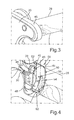
- FIG. 3 is part of a schematic perspective view of the exhaust gas aftertreatment device
- FIG. 4 is part of a schematic perspective view of the exhaust gas aftertreatment device
- FIG. 5 is part of a schematic and perspective sectional view of the exhaust gas aftertreatment device
- FIG. 6 is a schematic perspective view of the baffle according to a first embodiment.
- FIG. 7 is a schematic perspective view of the baffle according to a second embodiment.
- FIG. 1 shows a schematic top view of an exhaust gas aftertreatment device 10 for a combustion engine of a motor vehicle in the form of a utility motor vehicle, the combustion engine being configured as an internal combustion engine.
- the exhaust gas aftertreatment device 10 includes an exhaust pipe element in the form of an exhaust gas aftertreatment box 12 which is a guide element for guiding exhaust gas of the combustion engine.
- the exhaust gas aftertreatment box 12 is an at least substantially box-like container for guiding the exhaust gas which can flow through the exhaust gas aftertreatment box 12 (exhaust pipe element).
- the exhaust gas aftertreatment box 12 is arranged in an exhaust tract of the combustion engine and fluidically connected to an exhaust gas pipe through which the exhaust gas can flow.
- the exhaust gas pipe By means of the exhaust gas pipe the exhaust gas leaving combustion chambers in the form of cylinders of the combustion engines is fed into the exhaust gas aftertreatment box 12 so that the exhaust gas can flow from the exhaust gas pipe into the exhaust gas aftertreatment box 12 and can flow through it—as indicated in FIG. 1 by directional arrows 14 , 16 , 18 , 20 and 22 .
- the exhaust gas aftertreatment box 12 includes first guide portions 24 bounding respective exhaust gas guide ducts 26 .
- the exhaust gas guide ducts 26 are at least in portions fluidically separate from each other, and the exhaust gas can flow through the exhaust gas guide ducts 26 in a first flow direction which is indicated by the directional arrows 14 .
- the exhaust gas flows through the exhaust gas guide ducts 26 in a first flow direction during a fired operation of the combustion engine.
- the first guide portions 24 form respective connection elements by means of which each first guide portion 24 is fluidically connectable to a particle filter.
- the particle filters are not shown in FIG. 1 and are arranged in parallel to each other with regard to the flow of the exhaust gas through the particle filters and the first guide portions 24 . Accordingly, the guide elements 24 are fluidically arranged in parallel to each other.
- the combustion engine is a diesel engine which can be operated on liquid fuel in the form of diesel.
- the particle filters which are accordingly also referred to as diesel particle filters (DPF) in this connection serve for filtering particles contained in the exhaust gas from the exhaust gas.
- the exhaust gas aftertreatment box 12 also includes a second guide portion 28 which is also referred to as a hydraulic pipe or a hydrolysis tube through which the exhaust gas of the combustion engine can flow in a second flow direction which is illustrated by the directional arrow 18 .
- the second flow direction is opposite to the first flow direction.
- the exhaust gas during a fired operation of the combustion engine flows through the first guide portions 24 in the first flow direction and through the second guide portion 28 in the second flow direction which is contrary to the first flow direction.
- the exhaust gas aftertreatment box 12 includes a third guide portion in the form of a first collection chamber 30 .
- the first collection chamber 30 is fluidically connected both to the first guide portions 24 as well as the second guide portion 28 so that the guide portions 24 , 28 are fluidically connected to each other via the first collection chamber 30 .
- the exhaust gas flowing from the first guide portions 24 into the collection chamber 30 is collected in the collection chamber 30 and by means of the collection chamber 30 —as it is illustrated by the directional arrow 16 in FIG. 1 —is redirected from the first flow direction indicated by the directional arrows 14 into the second flow direction indicated by the directional arrow 18 .
- a particularly small construction space required by the exhaust gas aftertreatment device 10 can be realized.
- the first collection chamber 30 which is also referred to as a DPF out chamber has an exhaust duct 31 through which the exhaust gas flowing from the first guide portions 24 to the second guide portion 28 can flow.
- the second guide portion 28 is fluidically connected with the first collection chamber 30 on one side.
- the second guide portion 28 is fluidically connected with a fourth guide portion in the form of a second collection chamber 32 of the exhaust gas aftertreatment box 12 so that the exhaust gas flowing through the second guide portion 28 flows from the latter into the second collection chamber 32 .
- the exhaust gas aftertreatment box 12 includes two fifth guide portions 34 which are fluidically connected to the second collection chamber 32 .
- the fifth guide portions 34 bound respective exhaust gas guide ducts through which the exhaust gas can flow.
- the exhaust gas which flows into the second collection chamber 32 and is collected by the same flows from the second collection chamber 32 into the exhaust guide ducts and thus into the fifth guide portions 34 and flows through the fifth guide portions 34 in a third flow direction which is illustrated by the directional arrows 22 .
- the third flow direction corresponds to the first flow direction.
- the exhaust gas guide ducts of the respective fifth guide portions 34 are at least in portion separate from each other.
- a respective connection element is formed by means of which the fifth guide portions 34 are fluidically connected to a respective SCR catalytic converter 36 (SCR—Selective Catalytic Reduction).
- SCR Selective Catalytic Reduction
- the SCR catalytic converters 36 serve for denitriding the exhaust gas. This means the SCR catalytic converters 36 are used for at least reducing nitrogen oxides (NOx) contained in the exhaust gas.
- the first guide portions 24 and the fifth guide portions 34 are arranged at different levels of height, i.e., in planes that are spaced apart from each other.
- the fifth guide portions 34 for instance in the vertical direction of the vehicle are arranged below the first guide portions 24 , i.e., they have a lower level than these.
- the exhaust gas in this setup is guided by means of the first collection chamber 30 in the vertical direction of the vehicle downwards to the second guide portion 28 which is arranged below the first guide portions 24 .
- the exhaust gas aftertreatment device 10 includes a dosage device 38 from which a urea doser mounting 39 can be seen in FIG. 2 .
- the dosage device 38 serves for introducing a reduction agent for the aftertreatment of the exhaust gas, i.e., for denitriding the exhaust gas, at a feed point 40 into the first collection chamber 30 and, thus, the exhaust gas aftertreatment box 12 (exhaust pipe).
- the dosage device 38 opens into the exhaust duct 31 via the urea doser mounting 39 at the feed point 40 .
- the reduction agent is present in the form of an aqueous urea solution containing urea and, thus, ammoniac.
- an aqueous urea solution containing urea and, thus, ammoniac.
- the ammoniac (NH3) contained in the aqueous urea solution is used, the ammoniac reacting in the respective SCR catalytic converter 36 with the nitrogen oxides in the exhaust gas to produce water and nitrogen. This reaction is caused by the SCR catalytic converters 36 .
- the aqueous urea solution is stored in a tank which is not shown in the Figures.
- the tank of the utility vehicle is fluidically connected with the dosage device 38 .
- the urea doser mounting 39 has a through opening 43 through which the reduction agent can flow into the exhaust duct 31 .
- the urea doser mounting 39 serves for mounting a doser unit by means of which the reduction agent can be dosed into the exhaust duct 31 in a need-based manner.
- the exhaust gas aftertreatment device 10 includes an interference element 42 which is preferably arranged upstream of the feed point 40 in the first collection chamber 30 relative to the flow direction of the exhaust gas through the exhaust duct 31 .
- the interference element 42 introduces extra turbulence for intermixing enhancement. It also changes the flow field downstream to produce early intermixing. Moreover, the intermixing in the second guide portion 28 is improved due to the changed flow field as well. Therefore, an at least substantially homogenous mixture of exhaust gas and reduction agent can be produced when the mixture reaches the SCR catalytic converters 36 .
- the interference element 42 can be designed as a plate which is arranged in the first collection chamber 30 , in particular the exhaust duct 31 in such a way that the interference element 42 extends at least substantially perpendicularly to the flow direction of the exhaust gas.
- the interference element 42 has a plurality of through openings 44 through which the exhaust gas can flow. Thereby, turbulences of the exhaust gas can be caused so that a particularly good intermixing of the exhaust gas with the reduction agent can be realized.
- the interference element 42 can have a flange which is used for screwing the interference element 42 on the first collection chamber 30 . Thereby, a particular simple and time- and cost-efficient mounting of the interference element 42 can be realized.
- the interference element 42 is made of a metallic material.
- the interference element 42 can be welded to the first collection chamber 30 .
- the interference element 42 is configured as a perforated baffle, deflector or impact baffle which leads to a particularly good intermixing. Thus, undesired local accumulations of the reduction agent within the exhaust gas can be avoided.
- the interference element 42 and its arrangement it is also possible to realize a mixing zone in which an intermixing of the exhaust gas with the reduction agent occurs, already upstream and at the beginning of the second guide portion 28 , where a particularly advantageous mixing occurs by means of the second guide portion 28 .
- the second guide portion 28 is also referred to as a mixing tube. This results in a particularly good intermixing prior to the exhaust gas with the reduction agent finally flowing into the SCR catalytic converters 36 .
- the exhaust duct 31 is bounded at least partially by a wall 46 of the first collection chamber 30 .
- An outer surface of the wall 46 can be seen in FIG. 3 .
- the exhaust gas aftertreatment device 10 includes a baffle 48 which is arranged in the exhaust duct 31 .
- the baffle 48 is J-shaped and configured as an entirely closed dividing wall. This means the baffle 48 has no through opening through which the exhaust gas can flow at all.
- the exhaust duct 31 is divided into a first passage 50 having a first inlet opening 52 and a lower second passage 54 having a second inlet opening 56 .
- the exhaust gas entering the exhaust duct 31 can flow via the respective inlet openings 52 and 56 into and through the passages 50 and 54 so that a main flow of the exhaust gas is divided into a first partial flow flowing through the first passage 50 and a second partial flow flowing through the second passage 54 by means of the baffle 48 .
- the passages 50 and 54 are fluidically arranged in parallel. This means the partial flows can flow through the passages 50 and 54 in a fluidically parallel manner.
- the exhaust gas can flow through the passages 50 and 54 simultaneously or in a parallel manner so that the exhaust gas does not need to flow through one of the passages 50 and 54 at first and then through the other one of the passages 50 and 54 .
- the feed point 40 is arranged in the first passage 50 .
- the feed point 40 is shielded from the second passage 54 by means of the baffle 48 so that the second partial flow can be kept free of reduction agent and, thus, the second passage 54 can be kept free of deposit.
- the first passage 50 is arranged above the second passage 54 . Since the reduction agent (urea or urea spray) is introduced into the first passage 50 and mixed with the exhaust gas in the first passage 50 , the first passage 50 is used as an upper mixing passage. Urea droplets, this means reduction agent droplets, can hit an inner surface 58 of the baffle 48 .
- the second passage 54 is used as a lower heating passage.
- the baffle 48 will be heated from the bottom by the exhaust gas or the second partial flow through the second passage 54 .
- the second inlet opening 56 is arranged above or upstream the feed point 40 and, thus, the mixing zone, therefore, the second partial flow in the second passage 54 is urea free, i.e., reduction agent free, so that reduction agent deposit in the second passage 54 can be avoided. This ensures that the exhaust gas flowing through the clogging-free second passage 54 is always able to provide effective heating to the baffle 48 from the bottom.
- the baffle 48 can be heated effectively so that low temperature zones of the baffle 48 can be reduced or eliminated thereby reducing or eliminating urea deposit on the baffle 48 . It has been shown that reduction agent deposit (urea deposit) occurs in low temperature zones, and since such low temperature zones of the baffle 48 can be avoided, significant urea deposit on the baffle 48 can be avoided, too.
- the second partial flow leaving the second passage 54 mixes with the already partially mixed first partial flow leaving the first passage 50 downstream of the baffle 48 .
- the intermixed first partial flow and second partial flow form a further main flow of the exhaust gas, the main flow containing the reduction agent.
- This further main flow then flows through the hydraulic pipe in the form of the second guide portion 28 and through the SCR catalytic converters 36 .
- the baffle 48 is a splitting baffle which splits the main flow into the two partial flows and the exhaust duct 31 into the two passages 50 and 54 .
- the baffle 48 is preferably streamlined so that the baffle 48 is configured as a streamline splitting baffle (SSB).
- the baffle 48 has an at least substantially straight portion 60 and a curved portion 62 abutting the straight portion 60 , the curved portion 62 being arranged downstream of the straight portion 60 with respect to the flow direction of the exhaust gas through the exhaust duct 31 .
- the exhaust gas is guided by the straight portion 60 towards the curved portion 62 and diverted or deflected by the curved portion 62 particularly efficiently.
- the main body of the baffle 48 can essentially be a parallel extrusion of part of the guide portion 28 , and the extrusion intersects with an end wall of the collection chamber 30 to form the second passage 54 .
- space between the baffle 48 and the collection chamber 30 is not necessarily strictly constant, the space depending on the shape of the collection chamber 30 , in particular the wall 46 , in the relative position to the guide portion 28 .
- an end plate of the collection chamber 30 is not necessarily flat at the edges, so that the line of intersection is not of regular shape.
- the baffle 48 can be elongated into the guide portion 28 .
- the two-passage design of the exhaust duct 31 could be extended into the guide portion 28 so that a part or the whole guide portion 28 could be heated as well. Thereby, possible urea deposit in the guide portion can be eliminated or can be kept particularly low.
- baffle 48 as well as additional features on the baffle such as holes or fins could be further tailored to facilitate a particularly advantageous urea mixing within the exhaust duct 31 and, for example, the guide portion 28 . Since the second partial flow can be kept free of reduction agent, low temperature zones and, thus, urea deposit on the wall 46 can be avoided as well.
- FIGS. 5 and 6 show a first embodiment of the baffle 48 .
- FIG. 7 shows a second embodiment of the baffle 48 .
- respective end portions E can be bent towards the first passage 50 with respect to the other portion P of the baffle 48 , other portion P abutting the end portions E.
- a distance between the respective end portions E and the wall 46 is greater than a distance between the wall 46 and the other portion P.
- the distance between the wall 46 and the baffle 48 can be at least substantially constant across the extension of the baffle 48 .
- the distance between the baffle 48 and the wall 46 can vary across the extension of the baffle 48 .
- the flow of the exhaust gas can be influenced in a need-based and particularly efficient manner.
Abstract
Description
-
- 10 exhaust gas aftertreatment device
- 12 exhaust gas aftertreatment box
- 14 directional arrow
- 16 directional arrow
- 18 directional arrow
- 20 directional arrow
- 22 directional arrow
- 24 first guide portion
- 26 exhaust gas guide ducts
- 28 second guide portion
- 30 first collection chamber
- 31 exhaust duct
- 32 second collection chamber
- 34 fifth guide portion
- 36 SCR catalytic converter
- 38 dosage unit
- 39 urea doser mounting
- 40 feed point
- 43 through opening
- 42 interference element
- 44 through openings
- 46 wall
- 48 baffle
- 50 first passage
- 52 first inlet opening
- 54 second passage
- 56 second inlet opening
- 58 inner surface
- 60 straight portion
- 62 curved portion
- E end portion
- P further portion
Claims (3)
Applications Claiming Priority (2)
| Application Number | Priority Date | Filing Date | Title |
|---|---|---|---|
| GB1417685.3A GB2531012A (en) | 2014-10-07 | 2014-10-07 | Exhaust gas aftertreatment device for a combustion engine, in particular of a motor vehicle |
| GB1417685.3 | 2014-10-07 |
Publications (2)
| Publication Number | Publication Date |
|---|---|
| US20160194993A1 US20160194993A1 (en) | 2016-07-07 |
| US9932870B2 true US9932870B2 (en) | 2018-04-03 |
Family
ID=51946949
Family Applications (1)
| Application Number | Title | Priority Date | Filing Date |
|---|---|---|---|
| US14/875,970 Active 2035-10-30 US9932870B2 (en) | 2014-10-07 | 2015-10-06 | Exhaust gas aftertreatment device for a combustion engine, in particular of a motor vehicle |
Country Status (2)
| Country | Link |
|---|---|
| US (1) | US9932870B2 (en) |
| GB (1) | GB2531012A (en) |
Families Citing this family (1)
| Publication number | Priority date | Publication date | Assignee | Title |
|---|---|---|---|---|
| GB2539114A (en) | 2016-07-05 | 2016-12-07 | Daimler Ag | Mixing device and aftertreatment device |
Citations (8)
| Publication number | Priority date | Publication date | Assignee | Title |
|---|---|---|---|---|
| JPS4828819A (en) | 1971-08-17 | 1973-04-17 | ||
| US20100212292A1 (en) | 2007-07-24 | 2010-08-26 | Klaus Rusch | Assembly and Method for Introducing a Reducing Agent into the Exhaust Pipe of an Exhaust System of an Internal Combustion Engine |
| EP2282026A1 (en) | 2008-04-17 | 2011-02-09 | Toyota Jidosha Kabushiki Kaisha | Exhaust purifying system for internal combustion engine |
| EP2423479A2 (en) | 2010-08-27 | 2012-02-29 | Kabushiki Kaisha Toyota Jidoshokki | Exhaust gas purification apparatus |
| DE102011051878A1 (en) | 2010-10-14 | 2012-04-19 | Hyundai Motor Co. | HYDRAULIC CONTROL SYSTEM OF AUTOMATIC TRANSMISSION FOR A HYBRID VEHICLE |
| US20120144812A1 (en) | 2010-12-09 | 2012-06-14 | Kia Motors Corporation | Dosing module for exhaust post treatment system of vehicle |
| WO2013010700A1 (en) | 2011-07-21 | 2013-01-24 | Friedrich Boysen Gmbh & Co. Kg | Arrangement for introducing an additive into a gas flow |
| US8397492B2 (en) * | 2008-05-27 | 2013-03-19 | Hino Motors, Ltd. | Exhaust emission control device |
-
2014
- 2014-10-07 GB GB1417685.3A patent/GB2531012A/en not_active Withdrawn
-
2015
- 2015-10-06 US US14/875,970 patent/US9932870B2/en active Active
Patent Citations (8)
| Publication number | Priority date | Publication date | Assignee | Title |
|---|---|---|---|---|
| JPS4828819A (en) | 1971-08-17 | 1973-04-17 | ||
| US20100212292A1 (en) | 2007-07-24 | 2010-08-26 | Klaus Rusch | Assembly and Method for Introducing a Reducing Agent into the Exhaust Pipe of an Exhaust System of an Internal Combustion Engine |
| EP2282026A1 (en) | 2008-04-17 | 2011-02-09 | Toyota Jidosha Kabushiki Kaisha | Exhaust purifying system for internal combustion engine |
| US8397492B2 (en) * | 2008-05-27 | 2013-03-19 | Hino Motors, Ltd. | Exhaust emission control device |
| EP2423479A2 (en) | 2010-08-27 | 2012-02-29 | Kabushiki Kaisha Toyota Jidoshokki | Exhaust gas purification apparatus |
| DE102011051878A1 (en) | 2010-10-14 | 2012-04-19 | Hyundai Motor Co. | HYDRAULIC CONTROL SYSTEM OF AUTOMATIC TRANSMISSION FOR A HYBRID VEHICLE |
| US20120144812A1 (en) | 2010-12-09 | 2012-06-14 | Kia Motors Corporation | Dosing module for exhaust post treatment system of vehicle |
| WO2013010700A1 (en) | 2011-07-21 | 2013-01-24 | Friedrich Boysen Gmbh & Co. Kg | Arrangement for introducing an additive into a gas flow |
Non-Patent Citations (1)
| Title |
|---|
| Great Britain Search Report issued in counterpart Application No. GB1417685.3 dated Mar. 9, 2015 (Three (3) pages). |
Also Published As
| Publication number | Publication date |
|---|---|
| GB2531012A (en) | 2016-04-13 |
| GB201417685D0 (en) | 2014-11-19 |
| US20160194993A1 (en) | 2016-07-07 |
Similar Documents
| Publication | Publication Date | Title |
|---|---|---|
| CN109844274B (en) | Reducing agent mixer | |
| US9289724B2 (en) | Flow reversing exhaust gas mixer | |
| US9266075B2 (en) | Doser and mixer for a vehicle exhaust system | |
| CN109415964B (en) | Mixer device for an exhaust gas aftertreatment system of a motor vehicle, exhaust gas aftertreatment system and motor vehicle | |
| CN103321724B (en) | SCR catalytic muffler and mixing tube device thereof | |
| US20160319723A1 (en) | Mixer with integrated doser cone | |
| CN109477411B (en) | Fluid diverter to reduce deposits in a doser cone | |
| CN104379893A (en) | An inlet module for an emissions cleaning module | |
| EP3003543B1 (en) | Exhaust gas aftertreatment device | |
| CN203856551U (en) | Mixer module and emission cleaning module | |
| CN104487666A (en) | Exhaust purifier | |
| CN107980078B (en) | Exhaust gas aftertreatment device for an internal combustion engine of a motor vehicle | |
| US20140286832A1 (en) | Exhaust system | |
| CN104653259A (en) | Exhaust gas aftertreatment device | |
| US20230016427A1 (en) | Body mixing decomposition reactor | |
| US9228471B2 (en) | Mixing device for an exhaust system of a vehicle | |
| CN105051343A (en) | Modular exhaust treatment system | |
| US11208934B2 (en) | Systems and methods for mixing exhaust gas and reductant | |
| CN107435576A (en) | Integrated exhaust gas aftertreatment system | |
| GB2533790A (en) | Method, apparatus and device for improved aftertreatment of exhaust gas | |
| US9932870B2 (en) | Exhaust gas aftertreatment device for a combustion engine, in particular of a motor vehicle | |
| CN203742729U (en) | Catalytic converter assembly and exhaust system | |
| CN110792490B (en) | Inner box flow deflector for a vehicle exhaust system mixer assembly | |
| KR101837555B1 (en) | SCR Mixer And SCR Apparatus Including The Same | |
| CN109415963A (en) | Mixing arrangement and after-treatment device |
Legal Events
| Date | Code | Title | Description |
|---|---|---|---|
| AS | Assignment |
Owner name: DETROIT DIESEL CORPORATION, MICHIGAN Free format text: ASSIGNMENT OF ASSIGNORS INTEREST;ASSIGNOR:QUAN, PENG;REEL/FRAME:037576/0800 Effective date: 20160111 Owner name: DAIMLER AG, GERMANY Free format text: ASSIGNMENT OF ASSIGNORS INTEREST;ASSIGNOR:DETROIT DIESEL CORPORATION;REEL/FRAME:037576/0830 Effective date: 20160112 |
|
| STCF | Information on status: patent grant |
Free format text: PATENTED CASE |
|
| MAFP | Maintenance fee payment |
Free format text: PAYMENT OF MAINTENANCE FEE, 4TH YEAR, LARGE ENTITY (ORIGINAL EVENT CODE: M1551); ENTITY STATUS OF PATENT OWNER: LARGE ENTITY Year of fee payment: 4 |
|
| AS | Assignment |
Owner name: DAIMLER TRUCK AG, GERMANY Free format text: ASSIGNMENT OF ASSIGNORS INTEREST;ASSIGNOR:DAIMLER AG;REEL/FRAME:061629/0616 Effective date: 20220524 |