US9932771B1 - Ladder safety rails - Google Patents
Ladder safety rails Download PDFInfo
- Publication number
- US9932771B1 US9932771B1 US14/978,048 US201514978048A US9932771B1 US 9932771 B1 US9932771 B1 US 9932771B1 US 201514978048 A US201514978048 A US 201514978048A US 9932771 B1 US9932771 B1 US 9932771B1
- Authority
- US
- United States
- Prior art keywords
- upright tubular
- ladder
- cross member
- hand rails
- safety system
- Prior art date
- Legal status (The legal status is an assumption and is not a legal conclusion. Google has not performed a legal analysis and makes no representation as to the accuracy of the status listed.)
- Active
Links
Images


Classifications
-
- E—FIXED CONSTRUCTIONS
- E06—DOORS, WINDOWS, SHUTTERS, OR ROLLER BLINDS IN GENERAL; LADDERS
- E06C—LADDERS
- E06C7/00—Component parts, supporting parts, or accessories
- E06C7/18—Devices for preventing persons from falling
- E06C7/181—Additional gripping devices, e.g. handrails
-
- E—FIXED CONSTRUCTIONS
- E06—DOORS, WINDOWS, SHUTTERS, OR ROLLER BLINDS IN GENERAL; LADDERS
- E06C—LADDERS
- E06C7/00—Component parts, supporting parts, or accessories
- E06C7/18—Devices for preventing persons from falling
- E06C7/181—Additional gripping devices, e.g. handrails
- E06C7/182—Additional gripping devices, e.g. handrails situated at the top of the ladder
-
- E—FIXED CONSTRUCTIONS
- E06—DOORS, WINDOWS, SHUTTERS, OR ROLLER BLINDS IN GENERAL; LADDERS
- E06C—LADDERS
- E06C7/00—Component parts, supporting parts, or accessories
- E06C7/48—Ladder heads; Supports for heads of ladders for resting against objects
Landscapes
- Engineering & Computer Science (AREA)
- Mechanical Engineering (AREA)
- Ladders (AREA)
Abstract
A collapsible ladder safety system for a ladder having first and second vertical ladder rail and a plurality of step rungs extending between the first and second vertical rails, the system comprising first and second upright tubular hand rails and a cross member pivotally attached to each of the first and second parallel upright tubular hand rails. The tubular hand rails or cross member are releasably securable to an upper end of the ladder. The first and second upright tubular hand rails are collapsible against the cross member when not secured to the ladder.
Description
The present invention relates to a system and method for using safety rails for a ladder and more specifically, adjustable safety rails mountable to an extension ladder.
Stabilizers for ladders may provide extra support in maintaining a ladder in a specific position against a structure. The stabilizer may also provide a usable space between the ladder and the surface of the structure, such as when a painter needs to paint the surface on which the ladder is rested. However, the stabilizer provides stabilization for the ladder, not for the user. When a user needs to stabilize themselves on a ladder, the ladder rails or surface to which it leans are the only options. Moreover, when a user reaches the top portion of the ladder and must step off one of the top rungs, the user must balance themselves during that movement, sacrificing the safety of the user.
Bearing in mind the problems and deficiencies of the prior art, it is therefore an object of the present invention to provide a ladder safety system which allows a user to safely dismount the ladder from the top of the ladder by providing additional support.
It is another object of the present invention to provide the user with the stability and confidence to make a smooth, safe transition from the ground or base level to firm footed position on an elevated surface.
A further object of the invention is to provide stability while using the ladder as the platform while performing specific tasks.
It is yet another object of the present invention to provide a ladder safety system which when not in use, collapses to a compact footprint for transport and storage.
It is still another object of the present invention to provide a ladder safety system which allows a user to adjust the position of hand rails above the top of the ladder.
It is another object of the present invention to provide a fastener assembly which secures a cylindrical member to a surface in a rotatable or non-rotatable state.
Still other objects and advantages of the invention will in part be obvious and will in part be apparent from the specification.
The above and other objects, which will be apparent to those skilled in the art, are achieved in the present invention which is directed to a collapsible ladder safety system for a ladder having first and second vertical ladder rail and a plurality of step rungs extending between the first and second vertical rails, the system comprising first and second upright tubular hand rails and a cross member pivotally attached to each of the first and second parallel upright tubular hand rails, the tubular hand rails or cross member being releasably securable to an upper end of the ladder. The first and second upright tubular hand rails are collapsible against the cross member when not secured to the ladder. The collapsible ladder safety system may include a curved portion at an upper end of the first and second upright tubular hand rail. The collapsible ladder safety system may include a first and second pair of pivot clamps, the pivot clamps including a circular sleeve slidingly attached to the upright tubular member and a pin extending outward from the circular sleeve into an opening on the cross member. The collapsible ladder safety system may include a tension knob attached to each pivot clamp for adjusting the friction between the circular sleeve and the upright tubular member. The collapsible ladder safety system may include a lower brace member pivotally attached to each of the first and second upright tubular members, the lower brace member being parallel to the cross member. The first and second upright tubular members may be nearly parallel to the cross member when the system is in a closed position and the first and may be perpendicular to the cross member when the system is an opened position with the upright tubular hand rails fully secured to the ladder. The collapsible ladder safety system may include a support arm extending from each end of the cross member toward a surface for which the ladder is meant to lean against.
Another embodiment of the present invention is directed to a collapsible ladder safety system for a ladder having first and second vertical ladder rail and a plurality of step rungs extending between the first and second vertical rails, the system comprising first and second upright tubular hand rails, a curved portion at an upper end of the first and second upright tubular hand rail, and a cross member pivotally attached to each of the first and second upright tubular hand rails, the tubular hand rails or cross member being releasably securable to an upper end of the ladder. The collapsible ladder safety system may include a support arm extending from each end of the cross member toward a support wall for which the ladder is meant to lean against. The collapsible ladder safety system includes a lower brace member pivotally attached to each of the first and second upright tubular members, the lower brace member being parallel to the cross member, a first and second pair of pivot clamps, the pivot clamps including a circular sleeve slidingly attached to the upright tubular member and a pin extending outward from the circular sleeve into an opening on the cross member or the lower brace, and a tension knob attached to each pivot clamp for adjusting the friction between the circular sleeve and the upright tubular member. The first and second upright tubular members are nearly parallel to the cross member when the system is in a closed position and the first and second upright tubular hand rails are perpendicular to the cross member when the system is an opened position. The cross member may be attachable to the ladder rails or to at least one of the ladder step rungs. The upright tubular hand rails may be rotatable within the circular sleeve and rotation tension may be adjustable with the tension knob. The upright tubular hand rails may be vertically slidable within the circular sleeve and slide tension may be adjustable with the tension knob. The upright tubular hand rails may extend below the support arms and may be spaced away from the ladder rails sufficient for a user to grasp around the entire circumference of the tubular hand rail. The upright tubular hand rails may extend below the lower brace member.
Another embodiment of the present invention is directed to a method for using a collapsible ladder safety system for a ladder having first and second vertical ladder rail and a plurality of step rungs extending between the first and second vertical rails. The method comprises providing first and second parallel upright tubular hand rails, a curved portion at an upper end of the first and second parallel upright tubular hand rail, a cross member pivotally attached to each of the first and second upright tubular hand rails, a support arm extending from each end of the cross member toward a support wall for which the ladder is meant to lean against, a lower brace member pivotally attached to each of the first and second upright tubular hand rails, the lower brace member being parallel to the cross member, a first and second pair of pivot clamps, the pivot clamps including a circular sleeve slidingly attached to the upright tubular member and a pin extending outward from the circular sleeve into an opening on the cross member or the lower brace and a tension knob attached to each pivot clamp for adjusting the friction between the circular sleeve and the upright tubular hand rail. The method includes moving the first and second upright tubular hand rails from a closed position wherein the first and second upright tubular hand rails are nearly parallel to the cross member to a second open position wherein the first and second upright tubular hand rails are perpendicular to the cross member. The method includes securing the first and second upright tubular hand rails or the cross member to an upper portion of the ladder, placing the support arms against a wall or roof and adjusting the first and second parallel upright tubular hand rails to provide support for a user. The method may include the step of removing the first and second upright tubular hand rails or the cross member from the upper portion of the ladder when the user is finished using the ladder. The method may include the step of moving the first and second upright tubular hand rails from the second position to the first closed position.
Another embodiment of the present invention is directed to the collapsible ladder safety system as described above in combination with a fastening assembly for securing a cylindrical member to a surface, the fastening assembly comprising a cylindrical riser having a length and a central opening extending axially through the length of the cylinder. The cylindrical riser comprises a circular aperture having a diameter larger than diameter of the central opening, the circular aperture extending from a top end of the cylindrical riser to a distance less than the length of the cylindrical riser, a first cylindrical groove extending across the top surface of the cylindrical riser and a second cylindrical groove co-axially aligned with the first cylindrical groove and having a diameter larger than the first cylindrical groove. The fastening assembly includes a spring disposed in the aperture and a ring having a shaft extending radially from an arc of the ring, the shaft including external threads at a distal end thereof, the shaft extending through the spring, the cylindrical riser central opening and an opening in the surface to which the cylindrical member is secured. The fastening assembly includes a tension knob engagable with the threads of the shaft wherein the tension knob is disposed on the opposite side of the surface than the cylindrical riser. The ring is fully engaged with the second cylindrical groove when the fastening assembly is in a tightened position and the ring is partially engaged with the second cylindrical groove when the fastening assembly is in a loosened position. The cylindrical member is rotatable about the opening in the surface when the fastening assembly is in the loosened position and the cylindrical member is non-rotatably secured to the surface when the fastening assembly is in the tightened position.
Another embodiment of the present invention is directed to a fastening assembly for securing a cylindrical member to a surface, the fastening assembly comprising a cylindrical riser having a length and a central opening extending axially through the length of the cylinder. The cylindrical riser comprises a circular aperture having a diameter larger than diameter of the central opening, the circular aperture extending from a top end of the cylindrical riser to a distance less than the length of the cylindrical riser. The cylindrical riser comprises a first cylindrical groove extending across the top surface of the cylindrical riser and a second cylindrical groove co-axially aligned with the first cylindrical groove and having a diameter larger than the first cylindrical groove. The cylindrical riser comprises a spring disposed in the aperture, a ring having a shaft extending radially from an arc of the ring, the shaft including external threads at a distal end thereof, the shaft extending through the spring, the cylindrical riser central opening and an opening in the surface to which the cylindrical member is secured, and a tension knob engagable with the threads of the shaft wherein the tension knob is disposed on the opposite side of the surface than the cylindrical riser. The ring is fully engaged with the second cylindrical groove when the fastening assembly is in a tightened position and the ring is partially engaged with the second cylindrical groove when the fastening assembly is in a loosened position. The cylindrical member is rotatable about the opening in the surface when the fastening assembly is in the loosened position and the cylindrical member is non-rotatably secured to the surface when the fastening assembly is in the tightened position.
Another embodiment of the present invention is directed to a method of securing a cylindrical member to a surface comprising providing the fastening assembly as described above, providing a surface and a cylindrical member to secure to the surface and ensuring the ring shaft extends through the spring, riser opening and an opening in the surface. The method includes engaging the tension knob with the threads of the shaft, sliding the cylindrical member through the ring, tightening the tension knob until the cylindrical member is prevented from sliding through the ring and the rotating about the surface opening and partially loosening the tension knob to allow the cylindrical member to slide through the ring and rotate about the surface opening.
The features of the invention believed to be novel and the elements characteristic of the invention are set forth with particularity in the appended claims. The figures are for illustration purposes only and are not drawn to scale. The invention itself, however, both as to organization and method of operation, may best be understood by reference to the detailed description which follows taken in conjunction with the accompanying drawings in which:
In describing the preferred embodiment of the present invention, reference will be made herein to FIGS. 1-15 of the drawings in which like numerals refer to like features of the invention.
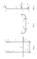
The ladder safety system as shown in the exploded view of FIG. 1 and the elevational views of FIGS. 2-4 includes a cross member 20 removably securable to a ladder and a lower brace 60 securable to the ladder below the cross member 20. A pair of hand rails 30 are attached to the cross member 20 and the lower brace 60, the hand rails 30, 31 including a upright tubular member 32 and a curved portion 34 extending from an upper end of each upright tubular member 32. Extending from the curved portion 34 is a straight handle portion 36. The upright tubular members 32 are pivotally attached to the cross member 20 and the lower brace 60 with pivot clams 40 which include a circular sleeve 42 slidingly attached to the upright tubular member 32 and a shaft 44 extending outward from the circular sleeve 42 and through an opening 28 on the cross member 20 or an opening 66 on the lower brace 60. The shaft 44 may be threaded so that female threads on a tension knob 46 engage the shaft 44. Tightening the tension knob 46 on the shaft 44 prevents the pivot clamps 40 from rotating on the cross member 20 or lower brace 60. The hand rails 30, 31 may also rotate separately and independently of one another about the upright tubular member cylindrical axis 98 in the directions indicated by rotation arrow 80 as shown in FIG. 8 .
The cross member 20 is an elongated tube or bar 22 with a curved portion 24 and a support arm 26 extending perpendicular to the elongated bar 20 at each end of the elongated bar 20. Support arm end caps 51 may be disposed on the distal end of the support arm 26. Alternately, a boot or other covering may be placed on the outside of support arm 26 for protecting the surface to which the support arm 26 is to be placed against. The boot may also help in preventing the ladder from sliding sideways. Bottom end caps 54 may be disposed on the bottom end of the hand rails 30 and handle end caps 56 may be disposed on the open ends of the straight handle portion 36.
To transport the ladder safety system when not attached to the ladder, the cross member 20 and hand rails 30, 31 are folded against each other. FIGS. 5 and 6 show the ladder safety system in a fully collapsed position wherein the longitudinal axes of cross member 20, lower brace 60 and upright tubular members 32 are within an angle of about 10°, dependent upon the position of the pivot clams on the upright tubular member, and substantially parallel to one another. FIG. 7 shows the ladder safety system being opened with the hand rails 30, 31 rotating clockwise in the direction of arrows 50 about the pivot clamps 40 and the cross member 20 and lower brace 60 moving away from one another in the direction of arrows 52, 54. The cross member 20 and lower brace 60 maintain a relative parallel position independent of the state of collapse of the ladder safety system. The upright tubular members 32 also maintain a parallel position relative to one another.
To descend from the elevated surface, the user may grab the left or right hand rail while in a backward position. The user may orient himself with the elevated surface and the top rung of the ladder. With his free hand, the user may grab the other hand rail and start the descent. As the user reaches the bottom of the hand rails, the user would transition his hands back to the ladder and complete the descent.
If the hand rails 30, 31 are not needed for a particular task, the two hand rails may be removed, leaving the cross member 20 to support the ladder against the vertical surface which the support arms 26 contact.
In a method of using the ladder safety system, the system shown mounted on the upper end of a ladder 90 in FIG. 9 , a user begins with the system in a folded position wherein the cross member, lower brace member and first and second hand rails being substantially parallel to one another as shown in FIG. 6 . The tension knobs 46 are loosened to allow the pivot clamps 40 to rotate about the pivot clamp shaft. The hand rails 30, 31 are rotated until they are perpendicular to the cross member 20. The ladder safety system is placed on the ground with the support arms 26 contacting the ground. The ladder 90 is then placed on top of the ladder safety system with an upper ladder step rung 95 placed adjacent the cross member 20 and a lower step rung 95′ adjacent the lower brace. A pair of U-bolts 70 and U-bolt straps 72 secure the cross member 20 to an upper ladder step rung 95 and a pair of U-bolts 70′ and U-bolt straps 72′ secure the lower brace 60 one of the lower step rungs 95′. The tension knobs 46 may be tightened while the ladder is on the ground to prevent the hand rails from rotating relative to the cross member 20 and cross brace 60. The ladder 90 is lifted upright and placed in the desired position.
This configuration now allows the user to climb the ladder in the normal fashion. As the user reaches the bottom of the hand rails, the hands transition from the ladder to the hand rails 30, 31 as the user ascends. The user may alternately transition hand placement from the ladder to the elevated surface while holding on to the hand rails 30, 31. Once firm footing is established, the user can release his or her grip from the hand rails 30, 31. The hand rails 30, 31 may be rotated as shown by the rotation arrows 41, 43 in FIG. 1 , so that the straight handle portions 36 are in different respective rotational orientations, such as facing in the direction of one another so that they are essentially planar. This position allows for more compact storage as well as allowing a ladder to be placed closer to a surface when the straight handle portions 36 are below the roof line. The straight handle portions 36 may be rotated forward so that the hand rails 30, 31 may be extended upward without the straight handle portions 36 contacting or getting in the way of the support surface to which the ladder is leaned against.
The ladder safety system may also be used with only one hand rail attached, or one hand rail completely retracted to a shorter length than the other. Hand rail 30 or hand rail 31 may be removed by rotating the tension knobs 46 off the pivot clamp shaft 44 and removing the pivot clamps or by releasing the tension on the tension knobs 46 and sliding the hand rail 30 or hand rail 31 from the pivot clamp circular sleeve 42.
For removal of the ladder safety system from the ladder 90, the ladder 90 may be placed so the system is easily accessible, such as placing the ladder 90 along the ground. The U-bolts 60 and securing plate 72 are removed from the cross member 20 and the lower brace 60. The ladder 90 may then be lifted from the ladder safety system or the ladder safety system may be lifted from the ladder 90, depending on the position of the ladder 90 on the ground. The tension knobs 46 are then rotated counter clockwise until the tension is released. The ladder safety system may then be collapsed by rotating the hand rails 30, 31 about the pivot clamp shaft 44.
In one embodiment of the pivot clamp, an improved fastening system is shown in the exploded views of FIGS. 10 and 11 . The fastening assembly may be used for securing a cylindrical member 190 to a surface 160 such as fastening the upright tubular member 32 to the cross member 20. The fastening assembly includes, as shown in FIGS. 12 and 13 , a cylindrical riser 100 having a central opening 108 extending axially through the length of the cylinder and a circular aperture 110 having a diameter larger than diameter of the central opening 108. The cylindrical riser may be metal, polymer, composite or any material which provides sufficient strength to secure the cylindrical member to the surface. The circular aperture 110 extends from a top end of the cylindrical riser 100 to a distance less than the length of the cylindrical riser 100. The cylindrical riser 100 includes a first substantially cylindrical groove 102 extending across the top surface of the cylindrical riser 100 and a second substantially cylindrical groove 104 co-axially aligned with and inset into the first cylindrical groove 102 and having a diameter larger than the first cylindrical groove 102. The substantially cylindrical grooves 102, 104 have walls that conform to the exteriors of a cylindrical member 190 and cylindrical ring 122, respectively, when the longitudinal axes of the member 190 and ring 122 are oriented perpendicular to the longitudinal axis of riser opening 108. The length of first substantially cylindrical groove 102 is across the entire width or diameter of riser 100, and the length of the inset second substantially cylindrical groove 104 is less, and may be as or slightly longer than the length of cylindrical ring 122 discussed further below.
The fastening system includes a spring 130 disposed in the aperture 110. The bottom of the circular aperture 110, includes a seat 112 formed by the end of opening 108 for engaging and supporting the bottom end of spring 130. The fastening system includes a ring 122 having a shaft 124 extending radially from an arc of the ring 122, the shaft 124 including external threads 136 at the end opposite the ring 122. As shown in FIGS. 14 and 15 , the shaft 124 extends through the spring 130, the cylindrical riser central opening 108 and a surface opening 162 of the surface 160 to which a cylindrical member 190 is secured. A tension knob 140 is engagable with the treads 136 of the shaft 124 to secure the cylindrical member 190 to the surface 160. The ring 120 is fully engaged with and seated in the second cylindrical groove 104 when the fastening assembly is in a tightened position and the ring 120 is partially engaged with the second cylindrical groove 104 when the fastening assembly is in a loosened position. The cylindrical member 190 may be rotatable about the opening 162 in the surface 160 when the fastening assembly is in the loosened position and the cylindrical member 190 is non-rotatably secured to the surface 160 when the fastening assembly is in the tightened position.
A method of using the fastening assembly shown in FIGS. 14 and 15 includes a user ensuring the ring shaft 124 extends through the spring 130, riser opening 108 and the opening 162 in the surface 160. The user engages the tension knob 140 with the threads 136 of the shaft 124 and slides the cylindrical member 190 through the ring 122. The user tightens the tension knob 140 until the cylindrical member 190 is prevented from sliding through the ring 122 and the rotating about the surface opening 162. The user may partially loosen the tension knob 140 to allow the cylindrical member 190 to slide through the ring 122 and rotate about the surface opening 162.
The present invention as describe above provides a ladder safety system which allows a user to have additional support to safely dismount the ladder from the top of the ladder. The present invention also provides the user with the stability and confidence to make a smooth, safe transition from the ground or base level to firm footed position on an elevated surface. Stability while using the ladder as the platform while performing specific tasks is also provided. The present invention also provides a ladder safety system which when not in use, collapses to a compact footprint for transport and storage as well as providing a ladder safety system which allows a user to adjust the position of hand rails above the top of the ladder. The present invention also provides a fastener assembly which secures a cylindrical member to a surface in a rotatable or non-rotatable state
While the present invention has been particularly described, in conjunction with a specific preferred embodiment, it is evident that many alternatives, modifications and variations will be apparent to those skilled in the art in light of the foregoing description. It is therefore contemplated that the appended claims will embrace any such alternatives, modifications and variations as falling within the true scope and spirit of the present invention.
Claims (17)
1. A collapsible ladder safety system for a ladder having first and second vertical ladder rail and a plurality of step rungs extending between the first and second vertical rails, the system comprising:
first and second upright tubular hand rails; and
a cross member pivotally attached at a first location to the first upright tubular handrail and at a second location to the second upright tubular handrail for rotation about a pair of parallel axes spaced apart and normal to the upright tubular hand rails, the tubular hand rails or cross member being releasably securable to an upper end of the ladder;
wherein the first and second upright tubular hand rails are collapsible by rotation about the axes to a position substantially parallel to the cross member when not secured to the ladder so the safety system may be easily stored or transported.
2. The collapsible ladder safety system of claim 1 including a curved portion at an upper end of the first and second upright tubular hand rail.
3. The collapsible ladder safety system of claim 1 including a first and second pair of pivot clamps detachable from the cross member, the pivot clamps including a circular sleeve slidingly attached to the upright tubular member and a pin extending outward from the circular sleeve into an opening on the cross member, the circular sleeve allowing axial rotation of the upright tubular members and the pin allowing rotation of the upright tubular members about the pin.
4. The collapsible ladder safety system of claim 3 including a tension knob attached to each pivot clamp for adjusting the friction between the circular sleeve and the upright tubular member.
5. The collapsible ladder safety system of claim 1 including a lower brace member pivotally attached to each of the first and second upright tubular members, the lower brace member being parallel to the cross member.
6. The collapsible ladder safety system of claim 1 wherein the first and second upright tubular members are nearly parallel to the cross member when the system is in a closed position and the first and second upright tubular hand rails are perpendicular to the cross member when the system is an opened position with the upright tubular hand rails fully secured to the ladder.
7. The collapsible ladder safety system of claim 1 including a support arm extending from each end of the cross member toward a surface for which the ladder is meant to lean against.
8. A collapsible ladder safety system for a ladder having first and second vertical ladder rail and a plurality of step rungs extending between the first and second vertical rails, the system comprising:
first and second upright tubular hand rails;
a curved portion at an upper end of the first and second upright tubular hand rail;
a cross member pivotally attached at a first location to the first upright tubular handrail and at a second location to the second upright tubular handrail for rotation about a pair of parallel axes spaced apart and normal to the upright tubular hand rails, the tubular hand rails or cross member being releasably securable to an upper end of the ladder;
a support arm extending from each end of the cross member toward a support wall for which the ladder is meant to lean against;
a lower brace member pivotally attached to each of the first and second upright tubular members, the lower brace member being parallel to the cross member;
a first and second pair of pivot clamps, the pivot clamps including a circular sleeve slidingly attached to the upright tubular member and a pin extending outward from the circular sleeve into an opening on the cross member or the lower brace; and
a tension knob attached to each pivot clamp for adjusting the friction between the circular sleeve and the upright tubular member;
wherein the first and second upright tubular members are rotatable about the axes to a position nearly parallel to the cross member when the system is in a closed position for storage or transportation and the first and second upright tubular hand rails are perpendicular to the cross member when the system is an opened position.
9. The collapsible ladder safety system of claim 8 wherein the cross member is attachable to the ladder rails.
10. The collapsible ladder safety system of claim 8 wherein the cross member is attachable to at least one of the ladder step rungs.
11. The collapsible ladder safety system of claim 8 wherein the upright tubular hand rails are rotatable within the circular sleeve and rotation tension is adjustable with the tension knob.
12. The collapsible ladder safety system of claim 8 wherein the upright tubular hand rails are vertically slidable within the circular sleeve and slide tension is adjustable with the tension knob.
13. The collapsible ladder safety system of claim 8 wherein the upright tubular hand rails extend below the support arms and are spaced away from the ladder rails sufficient for a user to grasp around the entire circumference of the tubular hand rail.
14. The collapsible ladder safety system of claim 8 wherein the upright tubular hand rails extend below the lower brace member.
15. A method for using the collapsible ladder safety system according to claim 8 , the method comprising:
providing the first and second parallel upright tubular hand rails, the curved portion at the upper end of the first and second parallel upright tubular hand rail, the cross member pivotally attached to each of the first and second upright tubular hand rails, the support arm extending from each end of the cross member toward the support wall for which the ladder is meant to lean against, the lower brace member pivotally attached to each of the first and second upright tubular hand rails, the lower brace member being parallel to the cross member, the first and second pair of pivot clamps, the pivot clamps including the circular sleeve slidingly attached to the upright tubular member and the pin extending outward from the circular sleeve into an opening on the cross member or the lower brace and the tension knob attached to each pivot clamp for adjusting the friction between the circular sleeve and the upright tubular hand rail;
moving the first and second upright tubular hand rails from a closed position wherein the first and second upright tubular hand rails are nearly parallel to the cross member to a second open position wherein the first and second upright tubular hand rails are perpendicular to the cross member;
securing the first and second upright tubular hand rails or the cross member to an upper portion of the ladder;
placing the support arms against a wall or roof; and
adjusting the first and second parallel upright tubular hand rails to provide support for a user.
16. The method of claim 15 including the step of removing the first and second upright tubular hand rails or the cross member from the upper portion of the ladder when the user is finished using the ladder.
17. The method of claim 16 including the step of moving the first and second upright tubular hand rails from the second position to the first closed position.
Priority Applications (1)
| Application Number | Priority Date | Filing Date | Title |
|---|---|---|---|
| US14/978,048 US9932771B1 (en) | 2014-12-22 | 2015-12-22 | Ladder safety rails |
Applications Claiming Priority (2)
| Application Number | Priority Date | Filing Date | Title |
|---|---|---|---|
| US201462095370P | 2014-12-22 | 2014-12-22 | |
| US14/978,048 US9932771B1 (en) | 2014-12-22 | 2015-12-22 | Ladder safety rails |
Publications (1)
| Publication Number | Publication Date |
|---|---|
| US9932771B1 true US9932771B1 (en) | 2018-04-03 |
Family
ID=61724967
Family Applications (1)
| Application Number | Title | Priority Date | Filing Date |
|---|---|---|---|
| US14/978,048 Active US9932771B1 (en) | 2014-12-22 | 2015-12-22 | Ladder safety rails |
Country Status (1)
| Country | Link |
|---|---|
| US (1) | US9932771B1 (en) |
Cited By (6)
| Publication number | Priority date | Publication date | Assignee | Title |
|---|---|---|---|---|
| US20180044985A1 (en) * | 2016-08-11 | 2018-02-15 | Bobo Ladders Llc | Boat or recreatonal vehicle ladder apparatus |
| US20180258697A1 (en) * | 2017-03-09 | 2018-09-13 | Milton R. Torin | Safety assembly for ladders |
| US20200224495A1 (en) * | 2019-01-16 | 2020-07-16 | Benjamin Johnson | Ladder stability enhancing assembly |
| US20200248507A1 (en) * | 2019-02-05 | 2020-08-06 | Wing Enterprises, Incorporated | Extendable walkthrough device for ladders |
| US20230023715A1 (en) * | 2021-07-13 | 2023-01-26 | Stephen D. ANDREWS | Ladder stabilizer |
| US20230048647A1 (en) * | 2021-08-10 | 2023-02-16 | Charles J. Mackarvich | Ladder walkthrough |
Citations (43)
| Publication number | Priority date | Publication date | Assignee | Title |
|---|---|---|---|---|
| US626839A (en) * | 1899-06-13 | Step- ladder | ||
| US636507A (en) * | 1899-08-02 | 1899-11-07 | Moritz Eichler | Step-ladder. |
| US922306A (en) * | 1907-12-31 | 1909-05-18 | Edward C Mead | Step-ladder. |
| US995273A (en) * | 1910-09-27 | 1911-06-13 | Edward C Mead | Attachment for ladders. |
| US1191922A (en) * | 1915-01-23 | 1916-07-18 | Safety Folding Ladder Company | Step-ladder. |
| CH116778A (en) * | 1926-02-08 | 1927-02-01 | Armand Grosjean | Device to increase the stability of ordinary ladders. |
| US2327317A (en) * | 1941-10-09 | 1943-08-17 | Fred D Randall | Attachment for ladders |
| US2439430A (en) * | 1946-05-20 | 1948-04-13 | George K Hurd | Hook attachment for ladders |
| US2881028A (en) * | 1957-10-11 | 1959-04-07 | James D Baird | Ladder platform |
| FR1193183A (en) * | 1958-03-12 | 1959-10-30 | Removable support device intended to be associated with a ladder | |
| US2934163A (en) * | 1957-10-23 | 1960-04-26 | Casimer S Ladewski | Ladder attachment |
| US3139155A (en) * | 1963-02-14 | 1964-06-30 | Le Roy C Skeels | Ladder handrail |
| US3157248A (en) * | 1962-11-16 | 1964-11-17 | Patent Scaffolding Co Inc | Mobile extendable scaffold |
| FR1390439A (en) * | 1964-01-17 | 1965-02-26 | advanced scale | |
| US3459277A (en) * | 1967-12-11 | 1969-08-05 | Ezra F Frederick | Ladder jacks |
| US3902700A (en) * | 1974-07-16 | 1975-09-02 | Doyle W Cox | Step ladder supported portable bridge-crane structure for lifting materials to the top of an adjacent building |
| US4061203A (en) * | 1977-02-28 | 1977-12-06 | Spencer Tool & Mfg. Co. Inc. | Ladder attachment |
| US4164269A (en) * | 1978-10-23 | 1979-08-14 | E. L. Hilts & Company | Safety bracket for securing ladder in place |
| US4202428A (en) * | 1974-03-14 | 1980-05-13 | Inventec International Limited | Ladder |
| US4502566A (en) * | 1983-03-28 | 1985-03-05 | Little Giant Industries, Inc. | Wall stand-off apparatus |
| US4998982A (en) * | 1988-12-16 | 1991-03-12 | Arnold William F | Metal ladder construction with reinforced side rails |
| US5261507A (en) * | 1992-11-17 | 1993-11-16 | Houston Industries Incorporated | Ladder standoff |
| US5373913A (en) * | 1989-02-08 | 1994-12-20 | Joseph H. Couch, III | Ladder stabilizer comprising intermediate connection from ladder to vertical structure |
| US5941343A (en) | 1998-06-03 | 1999-08-24 | Kelsey; Dale | Ladder safety accessory |
| US6012546A (en) | 1998-03-05 | 2000-01-11 | Bee; Dana A. | Safety ladder |
| US6394229B1 (en) * | 2000-08-28 | 2002-05-28 | Russell J. Hastreiter | Ladder attachment kit |
| US6397644B1 (en) * | 2000-05-18 | 2002-06-04 | Mark Douglas Gidding | Service vehicle ladder lock |
| US6457559B1 (en) * | 2000-07-26 | 2002-10-01 | Mark R. Schlueter | Foldable ladder |
| WO2004001176A1 (en) * | 2002-06-24 | 2003-12-31 | Freeman Donald B | Adjustable step ladder |
| US6739349B2 (en) * | 2002-06-11 | 2004-05-25 | Westfaliasurge, Inc. | Bulk milk tank with adjustable ladder |
| US20050236227A1 (en) * | 2004-04-23 | 2005-10-27 | Clark Bruce D | Ladder top walk through extensions |
| US7066299B1 (en) * | 2004-04-08 | 2006-06-27 | Jeffrey John Fleming | Portable ladder suspension apparatus or a portable ladder for suspension or the combination thereof |
| US20060261623A1 (en) * | 2005-05-20 | 2006-11-23 | John Kuznarik | Compact truck tailgate and general purpose utility ladder |
| FR2889240A1 (en) * | 2005-08-01 | 2007-02-02 | Duarib Soc Par Actions Simplif | Ascension device e.g. ladder, stabilizer, has legs and device deformably connected by fastening unit, where stabilizer uses support point in polygon formed by device ground support points and their orthogonal ground projections on structure |
| US20080190692A1 (en) * | 2007-02-12 | 2008-08-14 | Feik Frederick G | Ladder anchor |
| US20120012423A1 (en) * | 2009-03-25 | 2012-01-19 | Russell Edward Murphy | Emergency escape ladder |
| US20120061181A1 (en) * | 2010-09-15 | 2012-03-15 | Funmi Onobrakpeya | Easy step examination table device |
| US20120175188A1 (en) | 2011-01-12 | 2012-07-12 | Changliang Xu | Multi - Function Ladder Attachment |
| US8235175B1 (en) * | 2005-01-20 | 2012-08-07 | Feldhaus Daniel E | Ladder standoff arrangement |
| US20130199874A1 (en) * | 2010-12-23 | 2013-08-08 | Don M. Davis, Jr. | Ladder safety apparatus |
| US8602163B2 (en) | 2010-12-23 | 2013-12-10 | Don M. Davis, Jr. | Ladder safety apparatus |
| US20140159410A1 (en) * | 2003-07-31 | 2014-06-12 | Lippert Components, Inc. | Bed lift |
| US8839907B2 (en) * | 2010-12-23 | 2014-09-23 | Don M. Davis, Jr. | Ladder safety apparatus |
-
2015
- 2015-12-22 US US14/978,048 patent/US9932771B1/en active Active
Patent Citations (44)
| Publication number | Priority date | Publication date | Assignee | Title |
|---|---|---|---|---|
| US626839A (en) * | 1899-06-13 | Step- ladder | ||
| US636507A (en) * | 1899-08-02 | 1899-11-07 | Moritz Eichler | Step-ladder. |
| US922306A (en) * | 1907-12-31 | 1909-05-18 | Edward C Mead | Step-ladder. |
| US995273A (en) * | 1910-09-27 | 1911-06-13 | Edward C Mead | Attachment for ladders. |
| US1191922A (en) * | 1915-01-23 | 1916-07-18 | Safety Folding Ladder Company | Step-ladder. |
| CH116778A (en) * | 1926-02-08 | 1927-02-01 | Armand Grosjean | Device to increase the stability of ordinary ladders. |
| US2327317A (en) * | 1941-10-09 | 1943-08-17 | Fred D Randall | Attachment for ladders |
| US2439430A (en) * | 1946-05-20 | 1948-04-13 | George K Hurd | Hook attachment for ladders |
| US2881028A (en) * | 1957-10-11 | 1959-04-07 | James D Baird | Ladder platform |
| US2934163A (en) * | 1957-10-23 | 1960-04-26 | Casimer S Ladewski | Ladder attachment |
| FR1193183A (en) * | 1958-03-12 | 1959-10-30 | Removable support device intended to be associated with a ladder | |
| US3157248A (en) * | 1962-11-16 | 1964-11-17 | Patent Scaffolding Co Inc | Mobile extendable scaffold |
| US3139155A (en) * | 1963-02-14 | 1964-06-30 | Le Roy C Skeels | Ladder handrail |
| FR1390439A (en) * | 1964-01-17 | 1965-02-26 | advanced scale | |
| US3459277A (en) * | 1967-12-11 | 1969-08-05 | Ezra F Frederick | Ladder jacks |
| US4202428A (en) * | 1974-03-14 | 1980-05-13 | Inventec International Limited | Ladder |
| US3902700A (en) * | 1974-07-16 | 1975-09-02 | Doyle W Cox | Step ladder supported portable bridge-crane structure for lifting materials to the top of an adjacent building |
| US4061203A (en) * | 1977-02-28 | 1977-12-06 | Spencer Tool & Mfg. Co. Inc. | Ladder attachment |
| US4164269A (en) * | 1978-10-23 | 1979-08-14 | E. L. Hilts & Company | Safety bracket for securing ladder in place |
| US4502566A (en) * | 1983-03-28 | 1985-03-05 | Little Giant Industries, Inc. | Wall stand-off apparatus |
| US4998982A (en) * | 1988-12-16 | 1991-03-12 | Arnold William F | Metal ladder construction with reinforced side rails |
| US5373913A (en) * | 1989-02-08 | 1994-12-20 | Joseph H. Couch, III | Ladder stabilizer comprising intermediate connection from ladder to vertical structure |
| US5261507A (en) * | 1992-11-17 | 1993-11-16 | Houston Industries Incorporated | Ladder standoff |
| US6012546A (en) | 1998-03-05 | 2000-01-11 | Bee; Dana A. | Safety ladder |
| US5941343A (en) | 1998-06-03 | 1999-08-24 | Kelsey; Dale | Ladder safety accessory |
| US6397644B1 (en) * | 2000-05-18 | 2002-06-04 | Mark Douglas Gidding | Service vehicle ladder lock |
| US6457559B1 (en) * | 2000-07-26 | 2002-10-01 | Mark R. Schlueter | Foldable ladder |
| US6394229B1 (en) * | 2000-08-28 | 2002-05-28 | Russell J. Hastreiter | Ladder attachment kit |
| US6739349B2 (en) * | 2002-06-11 | 2004-05-25 | Westfaliasurge, Inc. | Bulk milk tank with adjustable ladder |
| WO2004001176A1 (en) * | 2002-06-24 | 2003-12-31 | Freeman Donald B | Adjustable step ladder |
| US20140159410A1 (en) * | 2003-07-31 | 2014-06-12 | Lippert Components, Inc. | Bed lift |
| US7066299B1 (en) * | 2004-04-08 | 2006-06-27 | Jeffrey John Fleming | Portable ladder suspension apparatus or a portable ladder for suspension or the combination thereof |
| US20050236227A1 (en) * | 2004-04-23 | 2005-10-27 | Clark Bruce D | Ladder top walk through extensions |
| US8235175B1 (en) * | 2005-01-20 | 2012-08-07 | Feldhaus Daniel E | Ladder standoff arrangement |
| US20060261623A1 (en) * | 2005-05-20 | 2006-11-23 | John Kuznarik | Compact truck tailgate and general purpose utility ladder |
| FR2889240A1 (en) * | 2005-08-01 | 2007-02-02 | Duarib Soc Par Actions Simplif | Ascension device e.g. ladder, stabilizer, has legs and device deformably connected by fastening unit, where stabilizer uses support point in polygon formed by device ground support points and their orthogonal ground projections on structure |
| US20080190692A1 (en) * | 2007-02-12 | 2008-08-14 | Feik Frederick G | Ladder anchor |
| US20120012423A1 (en) * | 2009-03-25 | 2012-01-19 | Russell Edward Murphy | Emergency escape ladder |
| US20120061181A1 (en) * | 2010-09-15 | 2012-03-15 | Funmi Onobrakpeya | Easy step examination table device |
| US20130199874A1 (en) * | 2010-12-23 | 2013-08-08 | Don M. Davis, Jr. | Ladder safety apparatus |
| US8602163B2 (en) | 2010-12-23 | 2013-12-10 | Don M. Davis, Jr. | Ladder safety apparatus |
| US8839908B2 (en) | 2010-12-23 | 2014-09-23 | Don M. Davis, Jr. | Ladder safety apparatus |
| US8839907B2 (en) * | 2010-12-23 | 2014-09-23 | Don M. Davis, Jr. | Ladder safety apparatus |
| US20120175188A1 (en) | 2011-01-12 | 2012-07-12 | Changliang Xu | Multi - Function Ladder Attachment |
Cited By (13)
| Publication number | Priority date | Publication date | Assignee | Title |
|---|---|---|---|---|
| US20180044985A1 (en) * | 2016-08-11 | 2018-02-15 | Bobo Ladders Llc | Boat or recreatonal vehicle ladder apparatus |
| US10961778B2 (en) * | 2016-08-11 | 2021-03-30 | Bobo Ladders Llc | Boat or recreational vehicle ladder apparatus |
| US10858887B2 (en) * | 2016-08-11 | 2020-12-08 | Bobo Ladders Llc | Boat or recreational vehicle ladder apparatus |
| US20180258697A1 (en) * | 2017-03-09 | 2018-09-13 | Milton R. Torin | Safety assembly for ladders |
| US10883310B2 (en) * | 2019-01-16 | 2021-01-05 | Benjamin Johnson | Ladder stability enhancing assembly |
| US20200224495A1 (en) * | 2019-01-16 | 2020-07-16 | Benjamin Johnson | Ladder stability enhancing assembly |
| US20200248507A1 (en) * | 2019-02-05 | 2020-08-06 | Wing Enterprises, Incorporated | Extendable walkthrough device for ladders |
| WO2020163373A1 (en) * | 2019-02-05 | 2020-08-13 | Wing Enterprises, Incorporated | Extendable walkthrough device for ladders |
| US11732530B2 (en) * | 2019-02-05 | 2023-08-22 | Little Giant Ladder Systems, Llc | Extendable walkthrough device for ladders |
| US20230023715A1 (en) * | 2021-07-13 | 2023-01-26 | Stephen D. ANDREWS | Ladder stabilizer |
| US11851950B2 (en) * | 2021-07-13 | 2023-12-26 | Ladder Armor Llc | Ladder stabilizer |
| US20230048647A1 (en) * | 2021-08-10 | 2023-02-16 | Charles J. Mackarvich | Ladder walkthrough |
| US11913283B2 (en) * | 2021-08-10 | 2024-02-27 | Charles J. Mackarvich | Ladder walkthrough |
Similar Documents
| Publication | Publication Date | Title |
|---|---|---|
| US9932771B1 (en) | Ladder safety rails | |
| US8839908B2 (en) | Ladder safety apparatus | |
| US20110247895A1 (en) | Walk through ladder platform | |
| US20160215563A1 (en) | Safety device for ladders | |
| US8839907B2 (en) | Ladder safety apparatus | |
| US8602163B2 (en) | Ladder safety apparatus | |
| US11732530B2 (en) | Extendable walkthrough device for ladders | |
| US9038778B1 (en) | Upright adaptor for ladder tree stand | |
| US8695762B1 (en) | Upright tree stand | |
| US20110226551A1 (en) | Quick-release ladder stabilizer and leveler | |
| US20100230208A1 (en) | Convertible multipurpose ladder stabilizers | |
| US20100116592A1 (en) | Adjustable Stepladder | |
| US8424639B1 (en) | Collapsible tree stand with dolly | |
| US9273515B2 (en) | Roofing ladder with a modular angularly adjustable platform | |
| US20120024630A1 (en) | Ladder Supported Tree Stand | |
| US10900282B2 (en) | Safety ladder | |
| EP2215323A1 (en) | A telescopic ladder assembly | |
| HUE029463T2 (en) | Collapsible ladder | |
| US20130256481A1 (en) | Ladder Accessory | |
| US20230023588A1 (en) | Safety accessory | |
| US9534443B1 (en) | Ladder and related methods | |
| US8701828B1 (en) | Stable stepladder with utility tray | |
| US20150191975A1 (en) | Vehicle Hitch Ladder Support Device | |
| US11856941B2 (en) | Ladder stand and activity rail assembly | |
| US20080035426A1 (en) | Ladder tray |
Legal Events
| Date | Code | Title | Description |
|---|---|---|---|
| AS | Assignment |
Owner name: SAFETY SOLUTIONS, INC., CONNECTICUT Free format text: ASSIGNMENT OF ASSIGNORS INTEREST;ASSIGNORS:BRAMWELL, MICHAEL;SHEARD, KEVIN;REEL/FRAME:037928/0262 Effective date: 20160303 |
|
| STCF | Information on status: patent grant |
Free format text: PATENTED CASE |
|
| CC | Certificate of correction | ||
| MAFP | Maintenance fee payment |
Free format text: PAYMENT OF MAINTENANCE FEE, 4TH YR, SMALL ENTITY (ORIGINAL EVENT CODE: M2551); ENTITY STATUS OF PATENT OWNER: SMALL ENTITY Year of fee payment: 4 |