US9925613B2 - Inverter-based generator and welding system - Google Patents
Inverter-based generator and welding system Download PDFInfo
- Publication number
- US9925613B2 US9925613B2 US14/229,353 US201414229353A US9925613B2 US 9925613 B2 US9925613 B2 US 9925613B2 US 201414229353 A US201414229353 A US 201414229353A US 9925613 B2 US9925613 B2 US 9925613B2
- Authority
- US
- United States
- Prior art keywords
- welding
- power output
- power
- inverter
- output
- Prior art date
- Legal status (The legal status is an assumption and is not a legal conclusion. Google has not performed a legal analysis and makes no representation as to the accuracy of the status listed.)
- Active, expires
Links
Images



Classifications
-
- B—PERFORMING OPERATIONS; TRANSPORTING
- B23—MACHINE TOOLS; METAL-WORKING NOT OTHERWISE PROVIDED FOR
- B23K—SOLDERING OR UNSOLDERING; WELDING; CLADDING OR PLATING BY SOLDERING OR WELDING; CUTTING BY APPLYING HEAT LOCALLY, e.g. FLAME CUTTING; WORKING BY LASER BEAM
- B23K9/00—Arc welding or cutting
- B23K9/10—Other electric circuits therefor; Protective circuits; Remote controls
- B23K9/1006—Power supply
- B23K9/1012—Power supply characterised by parts of the process
-
- B—PERFORMING OPERATIONS; TRANSPORTING
- B23—MACHINE TOOLS; METAL-WORKING NOT OTHERWISE PROVIDED FOR
- B23K—SOLDERING OR UNSOLDERING; WELDING; CLADDING OR PLATING BY SOLDERING OR WELDING; CUTTING BY APPLYING HEAT LOCALLY, e.g. FLAME CUTTING; WORKING BY LASER BEAM
- B23K9/00—Arc welding or cutting
- B23K9/10—Other electric circuits therefor; Protective circuits; Remote controls
- B23K9/1006—Power supply
- B23K9/1043—Power supply characterised by the electric circuit
-
- B—PERFORMING OPERATIONS; TRANSPORTING
- B23—MACHINE TOOLS; METAL-WORKING NOT OTHERWISE PROVIDED FOR
- B23K—SOLDERING OR UNSOLDERING; WELDING; CLADDING OR PLATING BY SOLDERING OR WELDING; CUTTING BY APPLYING HEAT LOCALLY, e.g. FLAME CUTTING; WORKING BY LASER BEAM
- B23K9/00—Arc welding or cutting
- B23K9/10—Other electric circuits therefor; Protective circuits; Remote controls
- B23K9/1006—Power supply
-
- B—PERFORMING OPERATIONS; TRANSPORTING
- B23—MACHINE TOOLS; METAL-WORKING NOT OTHERWISE PROVIDED FOR
- B23K—SOLDERING OR UNSOLDERING; WELDING; CLADDING OR PLATING BY SOLDERING OR WELDING; CUTTING BY APPLYING HEAT LOCALLY, e.g. FLAME CUTTING; WORKING BY LASER BEAM
- B23K9/00—Arc welding or cutting
- B23K9/10—Other electric circuits therefor; Protective circuits; Remote controls
- B23K9/1006—Power supply
- B23K9/1012—Power supply characterised by parts of the process
- B23K9/1037—Means preventing crater forming at the extremity of the seam
-
- B—PERFORMING OPERATIONS; TRANSPORTING
- B23—MACHINE TOOLS; METAL-WORKING NOT OTHERWISE PROVIDED FOR
- B23K—SOLDERING OR UNSOLDERING; WELDING; CLADDING OR PLATING BY SOLDERING OR WELDING; CUTTING BY APPLYING HEAT LOCALLY, e.g. FLAME CUTTING; WORKING BY LASER BEAM
- B23K9/00—Arc welding or cutting
- B23K9/10—Other electric circuits therefor; Protective circuits; Remote controls
- B23K9/1006—Power supply
- B23K9/1075—Parallel power supply, i.e. multiple power supplies or multiple inverters supplying a single arc or welding current
-
- B—PERFORMING OPERATIONS; TRANSPORTING
- B23—MACHINE TOOLS; METAL-WORKING NOT OTHERWISE PROVIDED FOR
- B23K—SOLDERING OR UNSOLDERING; WELDING; CLADDING OR PLATING BY SOLDERING OR WELDING; CUTTING BY APPLYING HEAT LOCALLY, e.g. FLAME CUTTING; WORKING BY LASER BEAM
- B23K9/00—Arc welding or cutting
- B23K9/32—Accessories
- B23K9/327—Means for transporting supplies
Definitions
- the invention relates generally to welding systems and, more particularly, to inverter-based welding systems.
- Welding is a process that has become increasingly ubiquitous in various industries and applications. As such, a variety of welding applications, such as construction and shipbuilding, may require welding devices that are portable and can easily be transported to a remote welding location. Accordingly, in some cases, it is often desirable for such welding devices to be operable as standalone units remote from a power grid or other primary power source. Therefore, a variety of welding systems utilizing alternate power sources, such as small gasoline-fueled engines, have been developed. However, certain welding tasks such as welding performed off-road or remotely to quickly repair certain equipment and/or other machinery, for example, may include load demands that are very small as compared to other larger welding tasks. It may be useful to provide a more compact and efficient portable welding system.
- a system in one embodiment, includes an engine configured to drive a generator to produce a first power output, and a first inverter communicatively coupled to the generator.
- the first inverter is configured to convert the first power output into a second power output.
- the system includes a second inverter communicatively coupled to the generator.
- the second inverter is configured to convert the first power output into a third power output.
- the third power output includes a welding power output.
- a welding power supply unit in a second embodiment, includes an engine configured to drive a generator to produce a first power output, and a first inverter communicatively coupled to the generator.
- the first inverter is configured to convert the first power output into a second power output.
- the welding power supply unit includes a second inverter communicatively coupled to the generator.
- the second inverter is configured to convert the first power output into a welding power output.
- the welding power supply unit includes a welding torch detachably coupled to the welding power supply unit and configured to receive the welding power output.
- a welding system in a third embodiment, includes an enclosure.
- the enclosure includes an engine configured to drive a generator to produce a first power output, and a plurality of inverters communicatively coupled to the generator.
- the plurality of inverters is configured to convert the first power output into a second power output and a third power output concurrently.
- the third power output includes a welding power output.
- FIG. 1 is a perspective view of an inverter-based power supply unit, which functions to power, control, and provide consumables to a welding operation and/or auxiliary equipment;
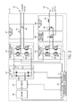
- FIG. 2 is a schematic diagram of the inverter-based power supply unit of FIG. 1 including a welding circuit, in accordance with present embodiments;
- FIG. 3 is a series of plots illustrating the power conversion techniques and outputs of the inverter-based power supply unit of FIG. 1 , in accordance with present embodiments.
- the inverter-based generator and welding system may be useful in permitting the system to be moved from place to place relatively easily, or may be designed as a generally stationary system.
- the inverter-based generator and welding system may be designed for field operation, in which case it may include an engine-generator unit within the enclosure that provides the necessary power for a given welding operation.
- the inverter-based generator and welding system may be designed for use in various applications and locations (e.g., remote locations, locations away from typical work areas or workstations, off-road locations, and so forth) in which one or more sources of utility power may be at least temporarily inaccessible.
- the inverter-based generator and welding system may be configured to operate as a standalone generator, a standalone welder, or concurrently as a standalone generator and as a standalone welder.
- the inverter-based generator and welding system may provide an operator with the advantage of having sufficient power for auxiliary equipment (e.g., lighting at a campsite or other off-road worksite) as well as sufficient power to perform one or more welding operations (e.g., at the campsite or the off-road worksite).
- FIG. 1 an embodiment of a generator and welding system, such as an inverter-based generator and welding system 10 , is illustrated in FIG. 1 .
- the inverter-based welding system 10 may provide power and control for a welding operation and/or auxiliary equipment.
- the inverter-based welding system 10 may include a power supply unit 12 enclosed in a cabinet or enclosure 14 .
- the inverter-based welding system 10 may be useful in enabling the power supply unit 12 to be moved from place to place relatively easily, or may be designed as a generally stationary system.
- the inverter-based welding system 10 may be designed for field operation, in which case it may include, for example, one or more of an engine-generator unit, a fuel cell, and an energy storage device within the enclosure 14 that provide the necessary power for a given welding operation or other application.
- the inverter-based welding system 10 may be designed for use in various locations (e.g., remote locations, locations away from typical work areas or workstations, off-road locations, and so forth) in which one or more sources of utility power may be at least temporarily inaccessible.
- the power supply unit 12 may operate as a standalone unit, generating the power necessary for a welding operation and/or auxiliary operations while isolated from additional power sources.
- the power supply unit 12 may include a control panel 16 , through which an operator may, for example, control the machine operational characteristics, such as power, weld output, and so forth, for a welding operation via dials and switches 18 .
- the control panel 16 may also include an auxiliary power output receptacle 20 and welding power output connectors 21 for outputting alternating current (AC) and/or direct current (DC) output power, respectively.
- AC alternating current
- DC direct current
- signals may be generated and received by one or more control circuits that may be included within the power supply unit 12 .
- the power supply unit 12 controller may implement the desired welding operation in accordance with these inputs. For example, in one embodiment, the controller may implement a constant current regime for use with a shielded metal arc welding (SMAW) or stick welding operation and/or process type.
- SMAW shielded metal arc welding
- an electrode assembly 22 may extend from the welding power output connectors 21 of the power supply unit 12 to the location of the weld.
- a first cable 24 and a welding torch 26 may be coupled to the power supply unit 12 as components of the electrode assembly 22 .
- the welding torch 26 may be used to secure a welding electrode suitable for shielded metal arc welding (SMAW) (e.g., stick welding) operations.
- SMAW shielded metal arc welding
- a work assembly 28 extending from the welding power output connectors 21 of the power supply unit 12 to the weld includes a second cable 30 terminating in a work lead clamp 32 .
- the work lead clamp 32 may be coupled to a workpiece 34 to create a circuit between the welding torch 26 , the workpiece 34 , and the power supply unit 12 . That is, as the welding operator, for example, contacts or closely approaches the tip of the electrode of the welding torch 26 to the workpiece 34 , an electrical circuit is completed through the cables 24 and 30 , the welding torch 26 , the workpiece 34 , and the work lead clamp 32 to generate an electrical arc between the electrode tip and the workpiece 34 to perform a weld of the workpiece 34 .
- a detachable (e.g., removable) receptacle 36 may be included as part of the power supply unit 12 .
- the detachable receptacle 36 may be useful in storing one or more components of the inverter-based welding system 10 .
- the detachable receptacle 36 may be a pouch, a tote, or similar receptacle that may couple to an exterior portion of the power supply unit 12 .
- the detachable receptacle 36 may be provided to facilitate the portability of the inverter-based welding system 10 .
- the detachable receptacle 36 may be used by an operator of the inverter-based welding system 10 to package or store one or more components (e.g., the cable 24 , the welding torch 26 , and so forth) of the electrode assembly 22 and/or components (e.g., the cable 30 , the work lead clamp 32 , and so forth) of the work assembly 28 .
- FIG. 2 illustrates a schematic embodiment of the inverter-based power supply unit 12 of FIG. 1 .
- the inverter-based power supply unit 12 may include an engine 38 , a generator 40 , a DC bus 42 , inverters 43 and 44 , a step-down and/or isolation transformer 46 , output circuits 47 and 48 , and control circuitry 50 all enclosed within the single enclosure 14 .
- the inverter-based power supply unit 12 may be used to generate commanded power output levels for an auxiliary operation and/or welding operation, as described in detail below. Such commanded power output levels may be commanded based on one or more of amperage, voltage, wire type, wire feed speed, electrode diameter, and so forth.
- the engine 38 may be used to drive the generator 40 to produce power (e.g., electrical power), which may be utilized to provide an auxiliary power output 52 (e.g., AC electrical output), to power an additional device or other auxiliary equipment (e.g., lights, grinding equipment, cutting tools, and so forth) and/or to produce a welding power output 54 (e.g., DC electrical output).
- power e.g., electrical power
- auxiliary power output 52 e.g., AC electrical output
- additional device or other auxiliary equipment e.g., lights, grinding equipment, cutting tools, and so forth
- a welding power output 54 e.g., DC electrical output
- the engine 38 may include a fuel source useful in providing power to the generator 40 .
- the engine 38 may include a combustion engine powered by gasoline, diesel, LP fuel, natural gas, or other fuels, and may be configured to drive one or more rotating drive shafts.
- the engine 38 may include an industrial gas/diesel engine having a power rating of below approximately 15 hp, below approximately 10 hp, or below approximately 5 hp.
- the generator 40 coupled to the engine 38 may convert the power output (e.g., mechanical energy) of the engine 38 into electrical power, producing an alternating current (AC) voltage output.
- the generator 40 may be rated at less than approximately 1000 watts (W), less than approximately 2000 W, less than approximately 3000 W, less than approximately 4000 W, or otherwise up to approximately 5000 W.
- the power supply unit 12 may include the DC bus 42 and the inverters 43 and 44 .
- the DC bus 42 may include a bridge rectifier 56 connected to a bus capacitance 58 (Cbus).
- the bridge rectifier 56 may include a configuration (e.g., an H-bridge configuration) of diodes (e.g., D 1 , D 2 , D 3 , and D 4 ) for converting (e.g., rectifying) the incoming AC voltage signal (e.g., 115V, 120V, 200V, 208V, 230V, or similar voltage rating) generated via the generator 40 into a filtered direct current (DC) voltage signal.
- DC direct current
- a boost circuit could be incorporated into the DC bus 42 to raise the voltage to the desired operational level.
- the rectified and filtered DC voltage signal may then be transmitted to power switches 60 (e.g., semiconductor switches Q 1 , Q 2 , Q 3 , Q 4 ) of the auxiliary inverter 43 or to power switches 62 (e.g., semiconductor switches Q 5 , Q 6 , Q 7 , Q 8 ) of the welding power inverter 44 to respectively produce the AC auxiliary power output 52 and the DC welding power output 54 .
- the power switches 60 may convert the rectified and filtered DC voltage signal into an AC voltage signal, which may be then filtered via an inductor 64 and capacitor 66 of the output circuit 47 to produce a constant AC auxiliary power output 52 .
- the power switches 60 and 62 may include any configuration of integrated power electronic switching devices such as insulated gate bipolar transistors (IGBTs), field-effect transistors (FETs), and so forth, which may be controlled (e.g., by the control circuitry 50 ) to switch from “ON” (e.g., activated) and “OFF” (e.g., deactivated) states to control the power conversion via the inverter 43 and/or inverter 44 , and by extension, the AC auxiliary power output 52 and the DC welding power output 54 .
- IGBTs insulated gate bipolar transistors
- FETs field-effect transistors
- the power switches 62 may convert the rectified and filtered DC voltage signal into an AC voltage signal, which may be then reduced (e.g., stepped down) via a step-down and/or isolation transformer 46 to a voltage level (e.g., approximately 70 VAC, or other similar voltage rating) suitable for producing a welding power output.
- the transformer 46 may be any device capable of reducing the AC voltage signal produced, for example, by the power switches 62 of the inverter 44 to a voltage level suitable for producing a welding power output to supply to the welding torch 26 .
- the transformer 46 may also be used to isolate the welding-specific circuitry of the inverter-based power supply unit 12 from the AC auxiliary power output 52 circuitry of the power supply unit 12 .
- the output circuit 48 may then convert the welding-level AC voltage signal received from the transformer 46 back into a DC voltage signal via an output rectifier 68 .
- the new DC voltage signal may be then useful for supporting various welding operations and/or processes (e.g., a SMAW welding process).
- the AC auxiliary power output 52 may be used to power another external device and/or other auxiliary equipment.
- the inverter-based power supply unit 12 may supply the voltage AC auxiliary power output 52 to external lighting equipment, grinding equipment, cutting tools, and so forth.
- the inverter-based power supply unit 12 may also be used to generate a welding power output, for example, to perform one or more welding operations.
- the inverter-based power supply unit 12 may operate markedly quieter than other generator and/or welding systems.
- the engine 38 , the generator 40 , the DC bus 42 , and the inverters 43 and 44 may each be controlled and/or commanded by the control circuitry 50 .
- the control circuitry 50 may include an analog control circuit, or it may include a processor 70 and/or other data processing circuitry that may be communicatively coupled to a memory 72 to execute instructions to control, for example, one or more parameters of the engine 38 , the generator 40 , and the bridge rectifier 56 , and the power switches 60 and 62 of the respective inverters 43 and 44 .
- These instructions may be encoded in programs or code stored in tangible non-transitory computer-readable medium, such as the memory 72 and/or other storage.
- the processor 70 may be a general purpose processor, system-on-chip (SoC) device, application-specific integrated circuit (ASIC), or other processor configuration.
- the memory 72 may include, for example, random-access memory (RAM), read-only memory (ROM), flash memory (e.g., NAND), and so forth.
- control circuitry 50 may be useful in controlling the power switches 60 and 62 of the respective inverters 43 and 44 , or other components of the inverter-based power supply unit 12 to produce a stabilized AC power output (e.g., AC auxiliary power output 52 ) to power auxiliary equipment and/or a stabilized DC welding power output to support one or more welding operations and/or processes.
- the inverter-based power supply unit 12 may be used to support a stick (SMAW) welding process, which may generally use a constant current (CC) welding power output controlled by the control circuitry 50 .
- SMAW stick
- CC constant current
- control circuitry 50 may control the amperage output (e.g., amperage of an electrical arc generated via the welding torch 26 ) to a predetermined CC value by adjusting voltage and/or amperage feedback signals detected at the output stage of the inverter 44 .
- the inverter-based power supply unit 12 may be used to perform other user-selected welding processes, such as a flux cored welding process, a metal inert gas (MIG) welding process, and the like.
- the welding power output 54 may be generated in place of, in addition to, or concurrently (e.g., at the same time) with the AC auxiliary power output 52 . That is, the power supply unit 12 may produce the AC auxiliary power output 52 and the DC welding power output 54 substantially simultaneously (e.g., occurring at substantially the same time) and/or concurrently (e.g., occurring in parallel or at substantially the same time).
- the power supply unit 12 may provide 3000 W of power as the AC auxiliary power output 52 , 3000 W of power as the DC welding power output 54 , or concurrently provide 1500 W for each of the AC auxiliary power output 52 and the DC welding power output 54 at substantially the same time.
- the power provided as the respective power outputs 52 and 54 may be dependent upon the specific auxiliary equipment receiving the power output 52 and/or the specific welding operation or task being performed via the power output 54 .
- the total power output e.g., 1000 W, 2000 W, 3000 W, 3500 W, and so forth
- the total power output may or may not be divided evenly between the respective power outputs 52 and 54 .
- the present embodiments of the inverter-based power supply unit 12 may be designed for use in various locations (e.g., remote locations, locations away from typical work areas or stations, off-road locations, and so forth), having the ability to operate as a standalone generator, a standalone welder, or concurrently as a standalone generator and as a standalone welder may allow an operator the advantage of having sufficient power for auxiliary equipment (e.g., lighting at a campsite or other off-road worksite) as well as sufficient power to perform one or more welding operations (e.g., at the campsite or the off-road worksite).
- auxiliary equipment e.g., lighting at a campsite or other off-road worksite
- welding operations e.g., at the campsite or the off-road worksite
- FIG. 3 depicts a series of waveform plots 76 , 78 , 80 , and 82 illustrating examples of the previously discussed power conversion and control techniques of the inverter-based power supply unit 12 implemented using, for example, the control circuitry 30 .
- the control circuitry 50 may generate a reference sine wave AC voltage signal 86 (e.g., modulating signal) to be compared against a generated triangular wave AC voltage signal 84 (e.g., saw-tooth carrier signal).
- the control circuitry 50 may also compare an inversion of the sine wave AC voltage signal 86 against the triangular wave AC voltage signal 84 .
- the AC voltage signal 86 may also be totally synthesized within software stored in the memory 72 of the in the control circuitry 50 .
- the signals 84 and 86 may then be used to drive and/or control the power switches 60 of the inverter 43 and/or the power switches 62 of the inverter 44 .
- the resultant output voltage signal of the inverter 43 and/or the inverter 44 may be a pulse-width modulated (PWM) inverted signal 90 as illustrated by plot 78 .
- PWM pulse-width modulated
- the signal 90 may be then filtered (e.g., filtered via the AC output circuit 47 ) to produce a filtered (e.g., “clean” and stabilized) AC voltage signal as the auxiliary power output 52 , as illustrated by plot 80 .
- auxiliary power output 52 may be provided at the power receptacle 20 of the inverter-based power supply unit 12 to which an external device and/or other auxiliary equipment (e.g., lighting equipment, grinding equipment, cutting tools, and so forth) may be coupled.
- auxiliary equipment e.g., lighting equipment, grinding equipment, cutting tools, and so forth
- a volt amp signal 91 of plot 82 may be reduced (e.g., stepped down) via the transformer 46 and converted via the DC output circuit 48 to produce a DC welding voltage signal (e.g., CC welding output) as the welding power output 54 , as illustrated by plot 82 .
- the welding power output 54 may be provided to the welding torch 26 of the inverter-based power supply unit 12 , which may be then used to generate an electrical arc to perform one or welding operations and/or processes. It should again be appreciated that the inverter-based power supply unit 12 may produce the auxiliary power output 52 and the welding power output 54 individually or substantially simultaneously (e.g., in parallel).
Landscapes
- Engineering & Computer Science (AREA)
- Physics & Mathematics (AREA)
- Plasma & Fusion (AREA)
- Mechanical Engineering (AREA)
- Arc Welding Control (AREA)
- Generation Of Surge Voltage And Current (AREA)
- Inverter Devices (AREA)
Priority Applications (8)
| Application Number | Priority Date | Filing Date | Title |
|---|---|---|---|
| US14/229,353 US9925613B2 (en) | 2014-03-28 | 2014-03-28 | Inverter-based generator and welding system |
| CA2938648A CA2938648C (en) | 2014-03-28 | 2015-01-06 | Inverter-based generator and welding system |
| PCT/US2015/010250 WO2015147953A1 (en) | 2014-03-28 | 2015-01-06 | Inverter-based generator and welding system |
| EP15701065.3A EP3122507B1 (de) | 2014-03-28 | 2015-01-06 | Wechselrichter basierender generator und schweisssystem |
| CN201580016399.5A CN106132619B (zh) | 2014-03-28 | 2015-01-06 | 逆变器式发电机和焊接系统 |
| MX2016009921A MX358236B (es) | 2014-03-28 | 2015-01-06 | Sistema generador y de soldadura a base de inversores. |
| US15/935,674 US10661374B2 (en) | 2014-03-28 | 2018-03-26 | Inverter-based generator and welding system |
| US16/883,556 US12042888B2 (en) | 2014-03-28 | 2020-05-26 | Inverter-based generator and welding system |
Applications Claiming Priority (1)
| Application Number | Priority Date | Filing Date | Title |
|---|---|---|---|
| US14/229,353 US9925613B2 (en) | 2014-03-28 | 2014-03-28 | Inverter-based generator and welding system |
Related Child Applications (1)
| Application Number | Title | Priority Date | Filing Date |
|---|---|---|---|
| US15/935,674 Continuation US10661374B2 (en) | 2014-03-28 | 2018-03-26 | Inverter-based generator and welding system |
Publications (2)
| Publication Number | Publication Date |
|---|---|
| US20150273608A1 US20150273608A1 (en) | 2015-10-01 |
| US9925613B2 true US9925613B2 (en) | 2018-03-27 |
Family
ID=52395236
Family Applications (3)
| Application Number | Title | Priority Date | Filing Date |
|---|---|---|---|
| US14/229,353 Active 2034-06-29 US9925613B2 (en) | 2014-03-28 | 2014-03-28 | Inverter-based generator and welding system |
| US15/935,674 Active 2034-11-29 US10661374B2 (en) | 2014-03-28 | 2018-03-26 | Inverter-based generator and welding system |
| US16/883,556 Active 2034-08-06 US12042888B2 (en) | 2014-03-28 | 2020-05-26 | Inverter-based generator and welding system |
Family Applications After (2)
| Application Number | Title | Priority Date | Filing Date |
|---|---|---|---|
| US15/935,674 Active 2034-11-29 US10661374B2 (en) | 2014-03-28 | 2018-03-26 | Inverter-based generator and welding system |
| US16/883,556 Active 2034-08-06 US12042888B2 (en) | 2014-03-28 | 2020-05-26 | Inverter-based generator and welding system |
Country Status (6)
| Country | Link |
|---|---|
| US (3) | US9925613B2 (de) |
| EP (1) | EP3122507B1 (de) |
| CN (1) | CN106132619B (de) |
| CA (1) | CA2938648C (de) |
| MX (1) | MX358236B (de) |
| WO (1) | WO2015147953A1 (de) |
Cited By (5)
| Publication number | Priority date | Publication date | Assignee | Title |
|---|---|---|---|---|
| US20200306863A1 (en) * | 2019-03-29 | 2020-10-01 | Illinois Tool Works Inc. | Methods and apparatus to convert welding-type power to welding-type power and resistive preheating power |
| US20210296057A1 (en) * | 2020-03-23 | 2021-09-23 | Autab, Llc | Battery-ultracapacitor stud welder |
| US20210299774A1 (en) * | 2020-03-31 | 2021-09-30 | Illinois Tool Works Inc. | Methods and apparatus to synergically control a welding-type output during a welding-type operation |
| US11897062B2 (en) | 2018-12-19 | 2024-02-13 | Illinois Tool Works Inc. | Systems, methods, and apparatus to preheat welding wire |
| US12208476B2 (en) | 2015-12-10 | 2025-01-28 | Illinois Tool Works Inc. | Systems, methods, and apparatus to preheat welding wire |
Families Citing this family (14)
| Publication number | Priority date | Publication date | Assignee | Title |
|---|---|---|---|---|
| US20160175968A1 (en) * | 2014-12-19 | 2016-06-23 | Illinois Tool Works Inc. | Method and apparatus for providing welding and auxiliary power |
| US10751826B2 (en) * | 2015-12-31 | 2020-08-25 | Illinois Tool Works Inc. | Constant current control systems and methods |
| US11084115B2 (en) * | 2017-08-31 | 2021-08-10 | Illinois Tool Works Inc. | Cooling for inverter-based engine-driven welding-type power supply |
| USD890089S1 (en) * | 2018-09-20 | 2020-07-14 | Shenzhen Poweroak Newener Co., Ltd | Portable power supply |
| IT201800020563A1 (it) * | 2018-12-20 | 2020-06-20 | Jasic Tech Europe S R L | Sistema di saldatura di tipo modulabile |
| USD911935S1 (en) * | 2019-01-18 | 2021-03-02 | Fna Group, Inc. | Inverter generator |
| USD899357S1 (en) * | 2019-03-07 | 2020-10-20 | Black & Decker Inc. | Generator |
| JP1651581S (de) * | 2019-05-10 | 2020-01-27 | ||
| USD942934S1 (en) * | 2019-12-28 | 2022-02-08 | Shenzhen Poweroak Newener Co., Ltd | Power station |
| USD942932S1 (en) * | 2019-12-28 | 2022-02-08 | Shenzhen Poweroak Newener Co., Ltd | Power station |
| CN111438425B (zh) * | 2020-04-13 | 2021-08-06 | 电王精密电器(北京)有限公司 | 一种多功能脉冲弧焊电源 |
| USD971828S1 (en) * | 2020-06-19 | 2022-12-06 | Shenzhen Del Contemporary Technology Ltd. | Battery |
| USD1005947S1 (en) * | 2022-01-27 | 2023-11-28 | Xuejiao ZHOU | Power station |
| USD1123849S1 (en) * | 2024-05-16 | 2026-04-28 | Chongqing Dinking Power Machinery Co., Ltd | Inverter generator |
Citations (12)
| Publication number | Priority date | Publication date | Assignee | Title |
|---|---|---|---|---|
| US5601741A (en) | 1994-11-18 | 1997-02-11 | Illinois Tool Works, Inc. | Method and apparatus for receiving a universal input voltage in a welding power source |
| US6469401B2 (en) | 1997-05-19 | 2002-10-22 | Illinois Tool Works Inc. | Engine driven welding power supply with inverter auxiliary power |
| US20030164645A1 (en) | 2002-03-04 | 2003-09-04 | Crandell John O. | Integrated mobile tool and welder power supply system |
| EP1484128A1 (de) | 2003-06-04 | 2004-12-08 | Illinois Tool Works Inc. | Bolzenschweissgerät |
| US6987242B2 (en) | 2000-03-31 | 2006-01-17 | Illinois Tool Works Inc. | Method and apparatus for receiving a universal input voltage in a welding, plasma or heating power source |
| US20060037953A1 (en) | 2004-08-17 | 2006-02-23 | Lincoln Global, Inc., A Delaware Corporation | Hybrid powered welder |
| WO2009029360A1 (en) | 2007-08-31 | 2009-03-05 | Hobart Brothers Company | Portable battery powered welder |
| US20090159577A1 (en) * | 2007-12-19 | 2009-06-25 | Illinois Tool Works Inc. | Multi-Stage Compressor in a Plasma Cutter |
| CN201287231Y (zh) | 2008-10-28 | 2009-08-12 | 上海沪工电焊机制造有限公司 | 基于dsp芯片的弧焊逆变控制系统 |
| US20090277881A1 (en) * | 2008-05-09 | 2009-11-12 | Illinois Tool Works Inc. | Plasma cutter with disconnectable torch and work assemblies |
| US20100187210A1 (en) * | 2004-06-01 | 2010-07-29 | Illinois Tool Works Inc. | Hybrid welding-type power source |
| US20110006046A1 (en) * | 2009-07-13 | 2011-01-13 | Illinois Tool Works Inc. | Hybrid welding systems and devices |
Family Cites Families (2)
| Publication number | Priority date | Publication date | Assignee | Title |
|---|---|---|---|---|
| US8426772B2 (en) * | 2009-09-02 | 2013-04-23 | Lincoln Global, Inc. | Auxiliary power supply for a welding machine |
| US20140042138A1 (en) * | 2012-08-10 | 2014-02-13 | Lincoln Global, Inc. | Hot-wire welding power supply |
-
2014
- 2014-03-28 US US14/229,353 patent/US9925613B2/en active Active
-
2015
- 2015-01-06 CA CA2938648A patent/CA2938648C/en active Active
- 2015-01-06 EP EP15701065.3A patent/EP3122507B1/de active Active
- 2015-01-06 MX MX2016009921A patent/MX358236B/es active IP Right Grant
- 2015-01-06 WO PCT/US2015/010250 patent/WO2015147953A1/en not_active Ceased
- 2015-01-06 CN CN201580016399.5A patent/CN106132619B/zh not_active Expired - Fee Related
-
2018
- 2018-03-26 US US15/935,674 patent/US10661374B2/en active Active
-
2020
- 2020-05-26 US US16/883,556 patent/US12042888B2/en active Active
Patent Citations (14)
| Publication number | Priority date | Publication date | Assignee | Title |
|---|---|---|---|---|
| US5601741A (en) | 1994-11-18 | 1997-02-11 | Illinois Tool Works, Inc. | Method and apparatus for receiving a universal input voltage in a welding power source |
| US6469401B2 (en) | 1997-05-19 | 2002-10-22 | Illinois Tool Works Inc. | Engine driven welding power supply with inverter auxiliary power |
| US6987242B2 (en) | 2000-03-31 | 2006-01-17 | Illinois Tool Works Inc. | Method and apparatus for receiving a universal input voltage in a welding, plasma or heating power source |
| US20030164645A1 (en) | 2002-03-04 | 2003-09-04 | Crandell John O. | Integrated mobile tool and welder power supply system |
| EP1484128A1 (de) | 2003-06-04 | 2004-12-08 | Illinois Tool Works Inc. | Bolzenschweissgerät |
| US20040245219A1 (en) * | 2003-06-04 | 2004-12-09 | Moran Sean Patrick | Stud welder |
| US20100187210A1 (en) * | 2004-06-01 | 2010-07-29 | Illinois Tool Works Inc. | Hybrid welding-type power source |
| US20060037953A1 (en) | 2004-08-17 | 2006-02-23 | Lincoln Global, Inc., A Delaware Corporation | Hybrid powered welder |
| US20120074116A1 (en) * | 2004-08-17 | 2012-03-29 | Lincoln Global, Inc. | Hybrid powered welder |
| WO2009029360A1 (en) | 2007-08-31 | 2009-03-05 | Hobart Brothers Company | Portable battery powered welder |
| US20090159577A1 (en) * | 2007-12-19 | 2009-06-25 | Illinois Tool Works Inc. | Multi-Stage Compressor in a Plasma Cutter |
| US20090277881A1 (en) * | 2008-05-09 | 2009-11-12 | Illinois Tool Works Inc. | Plasma cutter with disconnectable torch and work assemblies |
| CN201287231Y (zh) | 2008-10-28 | 2009-08-12 | 上海沪工电焊机制造有限公司 | 基于dsp芯片的弧焊逆变控制系统 |
| US20110006046A1 (en) * | 2009-07-13 | 2011-01-13 | Illinois Tool Works Inc. | Hybrid welding systems and devices |
Non-Patent Citations (1)
| Title |
|---|
| International Search Report from PCT application No. PCT/US2015/010250, dated Jun. 10, 2015, 11 pgs. |
Cited By (10)
| Publication number | Priority date | Publication date | Assignee | Title |
|---|---|---|---|---|
| US12208476B2 (en) | 2015-12-10 | 2025-01-28 | Illinois Tool Works Inc. | Systems, methods, and apparatus to preheat welding wire |
| US11897062B2 (en) | 2018-12-19 | 2024-02-13 | Illinois Tool Works Inc. | Systems, methods, and apparatus to preheat welding wire |
| US20200306863A1 (en) * | 2019-03-29 | 2020-10-01 | Illinois Tool Works Inc. | Methods and apparatus to convert welding-type power to welding-type power and resistive preheating power |
| CN111745270A (zh) * | 2019-03-29 | 2020-10-09 | 伊利诺斯工具制品有限公司 | 将焊接功率转换成焊接功率和电阻预加热功率的方法和设备 |
| CN111745270B (zh) * | 2019-03-29 | 2024-02-20 | 伊利诺斯工具制品有限公司 | 将焊接功率转换成焊接功率和电阻预加热功率的方法和设备 |
| US12583048B2 (en) * | 2019-03-29 | 2026-03-24 | Illinois Tool Works Inc. | Methods and apparatus to convert welding-type power to welding-type power and resistive preheating power |
| US20210296057A1 (en) * | 2020-03-23 | 2021-09-23 | Autab, Llc | Battery-ultracapacitor stud welder |
| US12260990B2 (en) * | 2020-03-23 | 2025-03-25 | Autab, Llc | Battery-ultracapacitor stud welder |
| US20210299774A1 (en) * | 2020-03-31 | 2021-09-30 | Illinois Tool Works Inc. | Methods and apparatus to synergically control a welding-type output during a welding-type operation |
| US12521809B2 (en) * | 2020-03-31 | 2026-01-13 | Illinois Tool Works Inc. | Methods and apparatus to synergically control a welding-type output during a welding-type operation |
Also Published As
| Publication number | Publication date |
|---|---|
| CN106132619A (zh) | 2016-11-16 |
| CA2938648A1 (en) | 2015-10-01 |
| US20200282486A1 (en) | 2020-09-10 |
| WO2015147953A1 (en) | 2015-10-01 |
| US20180214970A1 (en) | 2018-08-02 |
| US10661374B2 (en) | 2020-05-26 |
| CA2938648C (en) | 2019-11-12 |
| US12042888B2 (en) | 2024-07-23 |
| MX358236B (es) | 2018-08-10 |
| EP3122507B1 (de) | 2019-06-26 |
| US20150273608A1 (en) | 2015-10-01 |
| MX2016009921A (es) | 2017-04-10 |
| EP3122507A1 (de) | 2017-02-01 |
| CN106132619B (zh) | 2018-09-18 |
Similar Documents
| Publication | Publication Date | Title |
|---|---|---|
| US12042888B2 (en) | Inverter-based generator and welding system | |
| US20240009749A1 (en) | Welding system utilizing a distributed power bus | |
| EP1981676B1 (de) | Vorrichtung zum schweissen mittels batteriebetrieb | |
| US9839968B2 (en) | Welding power to auxiliary power conversion system and method | |
| CN105142841B (zh) | 具有辅助充电器的焊接系统 | |
| US9421632B2 (en) | Multi-output engine welder supplying full electrical power capacity to a single welding output | |
| US9981334B2 (en) | Dual power integrated MIG welder and generator system | |
| CN105189009A (zh) | 复合焊接控制技术 | |
| US20170028501A1 (en) | Welding System Having Multiple Weld Outputs | |
| CA2970277C (en) | Method and apparatus for providing welding and auxiliary power | |
| CN107635712A (zh) | 用于提供焊接和辅助电力的方法和设备 | |
| US20220258269A1 (en) | Energy storage caddy for welding system | |
| US20210114128A1 (en) | Variable speed engine driven generator for providing welding and auxiliary power | |
| US20140027442A1 (en) | Inductor and system for welding for maintaining welding arcs | |
| US8304685B2 (en) | System and method for converting welding power to plasma-cutting power | |
| US20190061037A1 (en) | Engine-Driven Welding-Type Power Supplies Configured to Simultaneously Use External and Engine Power | |
| KR20160071731A (ko) | Bldc 모터를 구비하는 용접 시스템 |
Legal Events
| Date | Code | Title | Description |
|---|---|---|---|
| AS | Assignment |
Owner name: HOBART BROTHERS COMPANY, OHIO Free format text: ASSIGNMENT OF ASSIGNORS INTEREST;ASSIGNORS:ROZMARYNOWSKI, SCOTT RYAN;SICKELS, DARRELL LEE;SIGNING DATES FROM 20140325 TO 20140326;REEL/FRAME:032557/0037 |
|
| STCF | Information on status: patent grant |
Free format text: PATENTED CASE |
|
| MAFP | Maintenance fee payment |
Free format text: PAYMENT OF MAINTENANCE FEE, 4TH YEAR, LARGE ENTITY (ORIGINAL EVENT CODE: M1551); ENTITY STATUS OF PATENT OWNER: LARGE ENTITY Year of fee payment: 4 |
|
| MAFP | Maintenance fee payment |
Free format text: PAYMENT OF MAINTENANCE FEE, 8TH YEAR, LARGE ENTITY (ORIGINAL EVENT CODE: M1552); ENTITY STATUS OF PATENT OWNER: LARGE ENTITY Year of fee payment: 8 |