US9923617B2 - Communication channel optimization systems and methods in multi-user communication systems - Google Patents
Communication channel optimization systems and methods in multi-user communication systems Download PDFInfo
- Publication number
- US9923617B2 US9923617B2 US14/257,949 US201414257949A US9923617B2 US 9923617 B2 US9923617 B2 US 9923617B2 US 201414257949 A US201414257949 A US 201414257949A US 9923617 B2 US9923617 B2 US 9923617B2
- Authority
- US
- United States
- Prior art keywords
- signals
- wireless devices
- state information
- channel state
- matrix
- Prior art date
- Legal status (The legal status is an assumption and is not a legal conclusion. Google has not performed a legal analysis and makes no representation as to the accuracy of the status listed.)
- Expired - Lifetime
Links
- 238000004891 communication Methods 0.000 title claims abstract description 100
- 238000000034 method Methods 0.000 title claims abstract description 29
- 238000005457 optimization Methods 0.000 title description 7
- 239000011159 matrix material Substances 0.000 claims description 92
- 238000012545 processing Methods 0.000 claims description 12
- 238000000354 decomposition reaction Methods 0.000 claims description 4
- 238000010586 diagram Methods 0.000 description 17
- 239000013598 vector Substances 0.000 description 17
- 230000005540 biological transmission Effects 0.000 description 15
- 238000000926 separation method Methods 0.000 description 9
- 239000010410 layer Substances 0.000 description 8
- 238000001514 detection method Methods 0.000 description 7
- 238000007476 Maximum Likelihood Methods 0.000 description 6
- 238000013459 approach Methods 0.000 description 5
- 230000000875 corresponding effect Effects 0.000 description 4
- 238000004088 simulation Methods 0.000 description 4
- 230000008901 benefit Effects 0.000 description 3
- 230000008859 change Effects 0.000 description 2
- 230000000694 effects Effects 0.000 description 2
- 238000005516 engineering process Methods 0.000 description 2
- 238000005562 fading Methods 0.000 description 2
- 230000008569 process Effects 0.000 description 2
- 230000005855 radiation Effects 0.000 description 2
- 230000003595 spectral effect Effects 0.000 description 2
- 241001522296 Erithacus rubecula Species 0.000 description 1
- 230000006978 adaptation Effects 0.000 description 1
- 230000003044 adaptive effect Effects 0.000 description 1
- 230000006835 compression Effects 0.000 description 1
- 238000007906 compression Methods 0.000 description 1
- 230000021615 conjugation Effects 0.000 description 1
- 230000002596 correlated effect Effects 0.000 description 1
- 238000009795 derivation Methods 0.000 description 1
- 239000011229 interlayer Substances 0.000 description 1
- 238000012986 modification Methods 0.000 description 1
- 230000004048 modification Effects 0.000 description 1
- 238000010606 normalization Methods 0.000 description 1
- 230000010363 phase shift Effects 0.000 description 1
- 230000009467 reduction Effects 0.000 description 1
- 238000013468 resource allocation Methods 0.000 description 1
- 238000012552 review Methods 0.000 description 1
- 238000000638 solvent extraction Methods 0.000 description 1
- 238000001228 spectrum Methods 0.000 description 1
- 230000009466 transformation Effects 0.000 description 1
- 238000000844 transformation Methods 0.000 description 1
Images


Classifications
-
- H—ELECTRICITY
- H04—ELECTRIC COMMUNICATION TECHNIQUE
- H04B—TRANSMISSION
- H04B7/00—Radio transmission systems, i.e. using radiation field
- H04B7/02—Diversity systems; Multi-antenna system, i.e. transmission or reception using multiple antennas
- H04B7/04—Diversity systems; Multi-antenna system, i.e. transmission or reception using multiple antennas using two or more spaced independent antennas
- H04B7/0413—MIMO systems
- H04B7/0456—Selection of precoding matrices or codebooks, e.g. using matrices antenna weighting
- H04B7/0482—Adaptive codebooks
-
- H—ELECTRICITY
- H04—ELECTRIC COMMUNICATION TECHNIQUE
- H04B—TRANSMISSION
- H04B7/00—Radio transmission systems, i.e. using radiation field
- H04B7/02—Diversity systems; Multi-antenna system, i.e. transmission or reception using multiple antennas
- H04B7/04—Diversity systems; Multi-antenna system, i.e. transmission or reception using multiple antennas using two or more spaced independent antennas
- H04B7/0413—MIMO systems
- H04B7/0417—Feedback systems
-
- H—ELECTRICITY
- H04—ELECTRIC COMMUNICATION TECHNIQUE
- H04B—TRANSMISSION
- H04B7/00—Radio transmission systems, i.e. using radiation field
- H04B7/02—Diversity systems; Multi-antenna system, i.e. transmission or reception using multiple antennas
- H04B7/04—Diversity systems; Multi-antenna system, i.e. transmission or reception using multiple antennas using two or more spaced independent antennas
- H04B7/0413—MIMO systems
- H04B7/0452—Multi-user MIMO systems
-
- H—ELECTRICITY
- H04—ELECTRIC COMMUNICATION TECHNIQUE
- H04B—TRANSMISSION
- H04B7/00—Radio transmission systems, i.e. using radiation field
- H04B7/02—Diversity systems; Multi-antenna system, i.e. transmission or reception using multiple antennas
- H04B7/04—Diversity systems; Multi-antenna system, i.e. transmission or reception using multiple antennas using two or more spaced independent antennas
- H04B7/06—Diversity systems; Multi-antenna system, i.e. transmission or reception using multiple antennas using two or more spaced independent antennas at the transmitting station
- H04B7/0613—Diversity systems; Multi-antenna system, i.e. transmission or reception using multiple antennas using two or more spaced independent antennas at the transmitting station using simultaneous transmission
- H04B7/0615—Diversity systems; Multi-antenna system, i.e. transmission or reception using multiple antennas using two or more spaced independent antennas at the transmitting station using simultaneous transmission of weighted versions of same signal
- H04B7/0619—Diversity systems; Multi-antenna system, i.e. transmission or reception using multiple antennas using two or more spaced independent antennas at the transmitting station using simultaneous transmission of weighted versions of same signal using feedback from receiving side
- H04B7/0621—Feedback content
- H04B7/0626—Channel coefficients, e.g. channel state information [CSI]
-
- H—ELECTRICITY
- H04—ELECTRIC COMMUNICATION TECHNIQUE
- H04L—TRANSMISSION OF DIGITAL INFORMATION, e.g. TELEGRAPHIC COMMUNICATION
- H04L1/00—Arrangements for detecting or preventing errors in the information received
- H04L1/02—Arrangements for detecting or preventing errors in the information received by diversity reception
- H04L1/06—Arrangements for detecting or preventing errors in the information received by diversity reception using space diversity
- H04L1/0618—Space-time coding
- H04L1/0637—Properties of the code
- H04L1/0656—Cyclotomic systems, e.g. Bell Labs Layered Space-Time [BLAST]
-
- H—ELECTRICITY
- H04—ELECTRIC COMMUNICATION TECHNIQUE
- H04L—TRANSMISSION OF DIGITAL INFORMATION, e.g. TELEGRAPHIC COMMUNICATION
- H04L25/00—Baseband systems
- H04L25/02—Details ; arrangements for supplying electrical power along data transmission lines
- H04L25/03—Shaping networks in transmitter or receiver, e.g. adaptive shaping networks
- H04L25/03006—Arrangements for removing intersymbol interference
- H04L2025/0335—Arrangements for removing intersymbol interference characterised by the type of transmission
- H04L2025/03426—Arrangements for removing intersymbol interference characterised by the type of transmission transmission using multiple-input and multiple-output channels
-
- H—ELECTRICITY
- H04—ELECTRIC COMMUNICATION TECHNIQUE
- H04L—TRANSMISSION OF DIGITAL INFORMATION, e.g. TELEGRAPHIC COMMUNICATION
- H04L25/00—Baseband systems
- H04L25/02—Details ; arrangements for supplying electrical power along data transmission lines
- H04L25/0202—Channel estimation
- H04L25/024—Channel estimation channel estimation algorithms
- H04L25/0242—Channel estimation channel estimation algorithms using matrix methods
- H04L25/0248—Eigen-space methods
-
- H—ELECTRICITY
- H04—ELECTRIC COMMUNICATION TECHNIQUE
- H04L—TRANSMISSION OF DIGITAL INFORMATION, e.g. TELEGRAPHIC COMMUNICATION
- H04L25/00—Baseband systems
- H04L25/02—Details ; arrangements for supplying electrical power along data transmission lines
- H04L25/03—Shaping networks in transmitter or receiver, e.g. adaptive shaping networks
- H04L25/03006—Arrangements for removing intersymbol interference
- H04L25/03343—Arrangements at the transmitter end
Definitions
- the invention relates to communication systems in general, and particularly to communication channel optimization in multi-user communication systems.
- the quality and capacity of a communication channel are affected by such factors as interference, allocation of communication resources, the communication schemes or algorithms used on the communication channel, and the particular communication equipment implemented at transmitting and receiving ends of the channel.
- processing operations intended to compensate for other communication channel effects are primarily receiver based. For example, interference cancellation is performed by a receiver in known communication systems.
- the implementation of different types of communication equipment in conjunction with the same type of channel, such as different communication terminals in a wireless communication system for instance, may affect received signal processing operations at all receivers.
- Communication terminals at the ends of a communication channel are seldom identical.
- user communication terminals at one end of a communication channel normally have much more limited resources than base stations.
- MIMO Multiple Input Multiple Output
- each receiver has at least as many antennas as a transmitter. This constraint is difficult to satisfy where communication equipment on opposite ends of a communication channel are significantly different, as in the case of wireless communication terminals and base stations in wireless communication systems, for example.
- resource limitations at one receiver in such a multi-user system can also affect other receivers in the system.
- a method of processing signals to be transmitted to receivers on communication channels includes determining pre-coding signal weights based on channel state information associated with the communication channels to provide proportional power allocation to the signals, and applying the signal weights to the signals.
- the channel state information is received from the receivers.
- the invention also provides, in another aspect, a method which includes receiving over a sub-group of communication channels a subset of signals to which pre-coding signal weights based on channel state information associated with the communication channels to provide proportional power allocation have been applied.
- the receiver uses inverses of the pre-coding signal weights based on channel state information associated with the sub-group of channels to decode the received subset of signals.
- the signals to be transmitted include respective groups of signals to be transmitted to the receivers, and the pre-coding weights are determined to separate the respective groups of signals. Decoding then separates individual signals in the received subset of signals.
- the invention provides a system for processing signals to be transmitted to receivers on communication channels.
- the system preferably includes an input for receiving the signals and a processor.
- the processor is configured to determine pre-coding signal weights based on channel state information associated with the communication channels to provide proportional power allocation to the signals, and to apply the signal weights to the signals.
- the system further includes multiple antennas which provide respective sub-MIMO channels to the receivers.
- the invention also provides a system that includes an input for receiving over a sub-group of communication channels a subset of signals to which pre-coding signal weights based on channel state information associated with the communication channels to provide proportional power allocation have been applied, and a processor.
- the processor is configured to decode the received subset of signals using inverses of the pre-coding signal weights based on channel state information associated with the sub-group of the channels.
- a further method of processing signals to be concurrently transmitted to receivers over communication channels includes determining channel state information for the communication channels, determining a spatial coding matrix which includes a respective set of spatial coding weights for each of the receivers based on the channel state information, and applying the spatial coding weights in the spatial coding matrix to the signals.
- a method in accordance with a still further aspect of the invention includes determining channel state information for a communication channel between a receiver and a transmitter, transmitting the channel state information to the transmitter, and receiving from the transmitter one of a plurality of demodulation matrices for demodulating subsequently received communication signals to which spatial coding weights comprising respective sets of spatial coding weights for multiple receivers have been applied.
- a network element for processing signals to be concurrently transmitted to multiple communication terminals in a communication network is also provided.
- the network element preferably includes an input configured to receive the signals, and a processor.
- the processor is configured to determine channel state information for each communication channel between the network element and the communication terminals, to determine a spatial coding matrix comprising a respective set of spatial coding weights for each of the communication terminals based on the channel state information, and to apply the spatial coding weights in the spatial coding matrix to the signals.
- a communication terminal for operation in a communication network.
- a processor in the terminal is configured to determine channel state information for communication channels between the communication terminal and a network element in the communication network.
- the terminal also includes at least one antenna for transmitting the channel state information from the communication terminal to the network element, receiving a demodulation matrix from the network element, and receiving signals concurrently transmitted to multiple communication terminals from the network element.
- the processor is further configured to demodulate the received signals using the demodulation matrix.
- FIG. 1 is a block diagram of a 6 ⁇ 6 MIMO system
- FIG. 2 is a block diagram of a decomposed 6 ⁇ 6 MIMO system
- FIG. 3 is a block diagram of a MIMO system, illustrating inter-user interference
- FIG. 4 is a block diagram of a MIMO system using polarized communication channels, illustrating inter-user interference
- FIG. 5 shows a block diagram of a MIMO system according to an embodiment of the invention
- FIG. 6 is a block diagram of a MIMO BLAST system
- FIG. 7 is a block diagram of a multi-user MIMO system in accordance with another embodiment of the invention.
- FIG. 8 is a block diagram of a conventional null beamforming MIMO system
- FIG. 9 is a block diagram of a known multi-user BLAST MIMO system
- FIG. 10 is a block diagram of a known round-robin TDM (Time Division Multiplexing) BLAST MIMO system
- FIG. 11 is a plot of BLER (Block Error Rate) versus SNR (Signal-to-Noise Ratio) for an embodiment of the invention and several known communication schemes;
- FIG. 12 is a plot of BLER versus Eb/No (Energy per Bit to Spectral Noise Density ratio) for an embodiment of the invention and several known communication schemes;
- FIG. 13 is a plot of BLER versus SNR for several embodiments of the invention.
- systems and methods which enhance the performance of communication channels in a communication system, to thereby improve, for example, the transmission performance of multi-user MIMO (Multiple Input Multiple Output) communication systems.
- MIMO Multiple Input Multiple Output
- a multi-data stream transmitter at a base transceiver station (BTS) that provides communication services for a coverage area or cell in a wireless communication system transmits communication signals to user terminals via multiple antennas.
- User terminals are also commonly referred to as user equipment (UE), communication devices, and mobile stations, for instance.
- UE user equipment
- multiple receive antennas are employed for each user.
- FIG. 1 is a block diagram of a 6 ⁇ 6 MIMO system, which includes a plurality of antennas 16 at a BTS 10 , and a plurality of antennas 18 and a MIMO decoder 20 at a UE 12 .
- 6 communication signals 14 intended for the UE 20 labelled as s 1 (1) through s 6 (1) are transmitted via the antennas 16 from the BTS 10 to the UE 12 .
- each of the antennas 18 receives the signals transmitted from the antennas 16 , and the received signals are decoded in a MIMO decoder 20 .
- BTSs include further components in addition to the antennas 16 , such as components to generate the signals s 1 (1) through s 6 (1) for instance.
- the UE 12 includes components to further process received signals decoded by the MIMO decoder 20 .
- the BTS 10 and the UE 12 normally support both transmit and receive operations.
- MIMO multi-user MIMO transmissions where each UE does not have at least the same number of antennas as a BTS. Instead, MIMO is typically used as a single “fat-pipe”, and multiple users are served through the use of time division techniques. In addition, it is practically difficult to realize very large dimension MIMO systems, 8 ⁇ 8 systems for example, due the physical size limitations of UEs. As the physical size of a UE is usually limited, the distance by which multiple antennas for larger dimension MIMO systems can be separated is also limited, such that the antennas at the UE become highly correlated. This drastically reduces the MIMO channel capacity.
- FIG. 2 is a block diagram of a decomposed 6 ⁇ 6 MIMO system.
- the decomposed 6 ⁇ 6 MIMO system includes antennas 32 at a BTS 22 , and three UEs 24 , 26 , 28 , each of which includes a pair of antennas 34 / 36 , 40 / 42 , 46 / 48 and a MIMO decoder 38 , 44 , 50 .
- signals s 1 (1) /s 2 (1) , s 1 (2) /s 2 (2) , s 1 (3) /s 2 (3) are transmitted via a respective antenna in each of a plurality of sub-groups, pairs in FIG. 2 , of the antennas 32 to corresponding UEs 24 , 26 , 28 .
- the superscripts ( 1 ), ( 2 ), ( 3 ) indicate for which UE 24 , 26 , 28 , a signal is intended.
- Each pair of the antennas 32 forms a 2 ⁇ 2 sub-MIMO channel with the pair of antennas of a respective one of the UEs 24 , 26 , 28 .
- each pair of signals s 1 (1) /s 2 (1) , s 1 (2) /s 2 (2) , s 1 (3) /s 2 (3) may be intended for a particular UE 24 , 26 , 28
- the antennas 34 / 36 , 40 / 42 , 46 / 48 in each of the UEs 24 , 26 , 28 receive communication signals from all of the antennas 32 .
- the number of receive antennas must be equal to or greater than the number of transmit antennas.
- the number of antennas that can be provided at a UE is limited.
- the number of receive antennas is typically smaller than the number of transmit antennas.
- FIGS. 3 and 4 are block diagrams of MIMO systems, and illustrate inter-user interference.
- the signals 58 labelled s 1 (1) /s 2 (1) , s 1 (2) /s 2 (2) , are transmitted from the BTS 52 via respective ones of each pair of the antennas 60 to the UEs 54 , 56 .
- Signals received by the antennas 62 / 64 , 68 / 70 in the UEs 54 , 56 are processed by the MIMO decoders 66 , 72 .
- Interference in the MIMO system of FIG. 3 is indicated at 73 .
- any communication signals that are received at one of the UEs 54 , 56 but intended for the other of the UEs 54 , 56 represent interference at that UE.
- versions of s 1 (2) and s 2 (2) received at the UE 54 represent interference.
- the signals 80 are transmitted from the BTS 74 via respective ones of each pair of the antennas 82 to the UEs 76 , 78 , received by the antennas 84 / 86 , 90 / 92 , and processed by the MIMO decoders 88 , 94 .
- Polarized channels provided by the vertical- and horizontal-polarization antennas V and H in the example system of FIG. 4 , reduce interference 95 relative to the general MIMO system of FIG. 3 , but do not cancel the inter-user interference to such a degree that interference cancellation is unnecessary.
- the task of interference cancellation is typically performed at a user terminal.
- downlink communication channel interference cancellation is effectively split between the BTS (transmit) side and the UE (receive) side.
- a BTS may perform inter-user separation based pre-coding of data to be transmitted, while at the UE side, a UE performs MIMO layer separation and decoding.
- One type of multi-user MIMO system in which the invention may be implemented delivers communication signals according to the layered space-time known as MIMO-BLAST concurrently to multiple users.
- MIMO-BLAST layered space-time
- Such a system is preferably realized with feedback of communication channel state information from each UE to a BTS.
- Channel state feedback techniques are very well suited for application in conjunction with fixed or nomadic wireless communication channels due to the slow variation of such channels, which allows accurate channel state information feedback from the UEs to the BTS.
- a closed-loop pre-coded transmit antenna array for sub-MIMO transmission preferably MIMO-BLAST transmission, in a multi-user environment.
- Channel state information is measured by or fed back to a BTS, and at the BTS side, jointly optimized weights are computed and applied to antenna input signals to cancel inter-user MIMO interference. Therefore, in one sense, a system in accordance with this embodiment of the invention may be considered as an adaptive weighted transmit antenna array operating in the MIMO-BLAST mode. This concept is a departure from the conventional beamforming phased antenna array.
- y [y 1 y 2 . . . y N ] T is a vector of communication signals received at a receiver;
- s [s 1 s 2 . . . s M ] T is a vector of communication signals transmitted by a transmitter;
- ⁇ [ ⁇ 1 ⁇ 2 . . . ⁇ N ] T is a vector of noise components affecting the transmitted communication signals;
- H [ h 11 h 12 ... h 1 ⁇ ⁇ M h 21 h 22 ... h 2 ⁇ ⁇ M ⁇ ⁇ ⁇ ⁇ h N ⁇ ⁇ 1 h N ⁇ ⁇ 2 ... h nM ] is a channel attenuation factors;
- N is a number of antennas at the receiver
- M is a number of antennas at the transmitter.
- the post-detection SNR signal-to-noise ratio for a decoded element s i of s is given by
- ⁇ i ⁇ s i ⁇ 2 ⁇ 2 ⁇ ⁇ g _ i ⁇ 2 , ( 4 )
- g i is the i th row of G
- ⁇ 2 represents the variance of the elements in ⁇ (assuming that all the elements in ⁇ have the same level of variance).
- the post-detection signal power is a fixed value
- System performance can be improved by reducing post-detection noise, which is represented by ⁇ g i ⁇ 2 .
- One possible issue to consider in this regard is whether, when a transmitter has information about H, pre-equalization can improve system performance.
- the SNR for this pre-equalized signal can be expressed as
- ⁇ i ⁇ s i ⁇ 2 ⁇ j _ i ⁇ 2 ⁇ ⁇ 2 , ( 7 ) where j i is the i th row of J.
- the pre-equalization approach is similar to power control, i.e., the weak user gets more power so that all the users are equal. However, this is not an efficient approach to utilize system power.
- pre-equalization matrix J is completely determined by the channel matrix H. That is, except for making up an identity matrix, there are no other kinds of optimizations in J.
- An embodiment of the invention provides for user separation at the transmitter.
- One preferred user separation technique allows the use of ML (Maximum Likelihood) detection schemes at a receiver, such that the diversity order for each receiver is increased.
- ML Maximum Likelihood
- system performance may be improved in at least two further aspects, namely, to enhance an equivalent channel matrix and proportional transmitting power allocation.
- FIG. 5 shows a block diagram of a MIMO system according to an embodiment of the invention.
- the system includes a BTS 100 having a pre-coder 106 and a plurality of antennas 108 , 110 , 112 , 114 , and UEs 102 , 104 , each having a plurality of antennas 116 / 118 , 122 / 124 and a MIMO decoder 120 , 126 .
- M 4
- M U*N i .
- the system of FIG. 5 is a MIMO BLAST system.
- FIG. 5 is one illustrative example of a system in which the invention may be implemented.
- the invention is in no way limited thereto. Extension of the principles of the present invention to systems having other dimensions will be apparent to those skilled in the art.
- the BTS 100 preferably uses the U degrees of freedom (one per UE 102 , 104 ) of the transmit antennas 108 , 110 , 112 , 114 to perform weighted pre-coding of the signals s 1 (1) , s 2 (1) , s 1 (2) , s 2 (2) in the pre-coder 106 , while reserving the N i degrees of freedom (one per receive antenna of each UE 102 , 104 ) of the transmit antennas 108 , 110 , 112 , 114 to maximize the N i ⁇ N i sub-MIMO channel capacity and proportional antenna power allocation for each user.
- each UE 102 , 104 decodes communication signals received at its antennas 116 / 118 , 122 / 124 , using ML or MMSE (Minimum Mean Squared Error) decoding, for example.
- ML or MMSE Minimum Mean Squared Error
- the N i antennas also provide diversity gain.
- the UE- 1 102 preferably determines and feeds back channel state information H 1 (4 ⁇ 2) to the BTS 100 .
- the UE- 2 104 similarly preferably determines and feeds back channel state information H 2 (4 ⁇ 2) to the BTS 100 .
- channel state information may instead be determined locally by the BTS 100 .
- channel state information determination is shown conceptually in FIG. 5 outside the UEs 102 , 104 .
- DSP digital signal processor
- a general-purpose processor adapted to execute signal processing software for example.
- channel state information Various techniques for determining channel state information will be apparent to those skilled in the art, including estimation based on pilot channels in CDMA (Code Division Multiple Access) systems or preambles and scattered pilot tones in OFDM (Orthogonal Frequency Division Multiplexing) systems, for example.
- CDMA Code Division Multiple Access
- OFDM Orthogonal Frequency Division Multiplexing
- the BTS 100 Based on the channel state information H 1 and H 2 , the BTS 100 computes an antenna weight matrix or pre-coding matrix P, which preferably cancels inter-user MIMO interference between UE- 1 102 and UE- 2 104 and maximizes MIMO system channel capacity for UE- 1 102 and UE- 2 104 .
- the set of elements in a pre-equalization matrix ⁇ j 11 ,j 21 ,j 12 ,j 22 ⁇ are used to satisfy the following condition:
- Equation (10) can be manipulated to the form of
- each UE has only one receive antenna and receives only one layer of the MIMO signal, then proportional power allocation may be achieved. However, if a UE has multiple antennas and receives multiple layers of signals, as in FIG. 5 , then the situation will be different.
- the pre-coder 106 at the BTS 100 determines and applies pre-coding weights to the signals s 1 (1) , s 2 (1) , s 1 (2) , s 2 (2) to perform the function of inter-user interference cancellation through user separation.
- Each receiver, UEs 102 , 104 in FIG. 5 then performs the function of inter-antenna interference cancellation.
- algorithms such as ML and iterative ZF (Zero Forcing)/MMSE can be used to further improve detection results.
- ZF Zero Forcing
- the pre-coding matrix P is selected so that the combined channel matrix C has the format of
- the combined channel matrix C has a form of U N i ⁇ N i sub-matrices, diagonal elements of which are respective diagonal elements of C. Elements of C outside the plurality of N i ⁇ N i sub-matrices are zero.
- C may be considered as having groups of rows associated with UEs and groups of columns respectively associated with antenna pairs.
- c 1 and c 2 are associated with the UE- 1 102 as described above, and the columns of C are respectively associated with the antennas 108 , 110 , 112 , 114 .
- the antenna pairs 108 / 110 and 112 / 114 provide sub-MIMO channels to the UEs 102 and 104 , each pair may be considered to be associated with a respective one of the UEs 102 and 104 .
- each element of C positioned in a row associated with a particular UE and a column corresponding to an antenna that is associated with a different UE is forced to zero by selection of pre-coding weights in the pre-coding matrix P.
- the first two columns of the pre-coding matrix P are determined such that they satisfy
- [ y 1 y 2 ] [ c 11 c 12 c 21 c 22 ] ⁇ [ s 1 s 2 ] , ( 17 ) which represents a 2 ⁇ 2 MIMO system.
- the diversity order is two.
- the decoders 120 , 126 decode received signals using an inverse matrix such as the Moore-Penrose pseudo-inverse matrix of a corresponding sub-matrix of P.
- Q 1 and Q 2 indicate sub-matrices of such an inverse matrix Q that relate to the UEs 102 , 104 , respectively.
- These matrices can be derived by each receiver based on channel estimation using pilot channels, for example.
- the BTS 100 sends pilot tones to UEs 102 , 104 , and each UE estimates the elements of its corresponding inverse sub-matrix.
- [ p 11 p 12 p 21 p 22 ] may be chosen according to different criteria, such as improving channel matrix condition and providing proportional power allocation, for example.
- the pre-coding weights for the UE- 1 102 may be set to
- c 11 and c 22 are enhanced constructively, while c 12 and c 21 are constructed randomly. Therefore, the condition of C becomes more robust.
- layer- 1 s 1 (1) and layer- 2 s 2 (1) are beamed onto antenna- 1 108 and antenna- 2 110 , respectively, following the MRC (Maximum Ratio Combining) criterion.
- the elements of P may be selected in an analogous manner.
- v is as defined above.
- a new scheme to further enhance multi-user MIMO system performance has been described.
- the above embodiments are based on splitting the interference cancellation task between a transmitter and receivers.
- a transmitter performs inter-user separation pre-coding to define sub-MIMO channels, while receivers perform individual layer separation.
- the transmitter and each receiver benefit from this task partitioning. From the transmitter point of view, since it is no longer required to provide individual layer separation, it has the freedom to perform beamforming, which results in more robust equivalent channel matrix, and proportional power allocation.
- the receiver since multiple antennas are receiving signals from multiple layers, when the ML decoding algorithm is used, additional diversity gain can be achieved.
- FIG. 6 is a block diagram of a MIMO BLAST system.
- the system of FIG. 6 includes a BTS 130 and a UE 132 .
- the BTS includes a modulator 134 , an S/P (serial-to-parallel) converter 136 , and a plurality of M antennas 140 .
- S/P serial-to-parallel
- FIG. 6 shows a general case of an M ⁇ N MIMO system. Although three representative signals and antennas are shown at the BTS 130 and the UE 132 , the invention is in no way restricted to any particular dimension of MIMO system. M and N may be equal to, larger than, or smaller than 3. Also, as described above in conjunction with FIG. 1 , BTSs and UEs typically include further components that have not been shown in FIG. 6 to avoid congestion in the drawing.
- BLAST a sequence of the modulated symbols, each symbol having a duration of T, from the modulator 134 , is serial-to-parallel converted in the S/P converter 136 into parallel transmission blocks in the signals 138 .
- Each transmission block consists of K ch symbols, where K ch is the number of spatial channels.
- K ch is equal to the number of antennas, M, at the BTS 130 . All of the symbols of a transmission block are simultaneously radiated into space, and each symbol is radiated by a respective one of the antennas 140 .
- the radiated signal requires spectrum width equal to a fraction (1/K ch ) of that of the original signal. This achieves a very high spectral efficiency.
- P s is the total transmitted power
- y , M, H, s , and ⁇ are as defined above.
- H is preferably independent Gaussian complex random variables, with zero mean and E ⁇
- 2 ⁇ 1 variances.
- the mean power of each radiated symbol is equal to unity, i.e., E ⁇
- 2 ⁇ 1.
- the MMSE algorithm provides a significant gain as contrasted with the ZF algorithm in a channel with Rayleigh fading.
- the MIMO channel capacity is proportional to min ⁇ N,M ⁇ . It well known that the throughput capacity of MIMO grows linearly with an increase of min ⁇ N,M ⁇ .
- Conventional MIMO-BLAST receiver processing schemes require co-processing of signals received by all antennas in the MIMO system. However, such a method cannot be applied for multi-user combined MIMO systems, as the signals received by all other UEs may not always be accessible to each UE. Therefore, usage of MIMO BLAST in multi-user systems to provide for multiple access may be inefficient, despite a marginal increase of throughput capacity at the expense of an increase in the number transmitting and receiving antennas.
- the capacity of a multi-user system with open-loop transmit diversity is determined by min ⁇ M,N 1 ,N 2 , . . . N U ⁇ , where U, as above, is the number of UEs in a multi-user system.
- U as above, is the number of UEs in a multi-user system.
- common throughput capacity will be limited by UEs with the least number of receiving antennas.
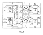
- FIG. 7 is a block diagram of a multi-user MIMO system in accordance with another embodiment of the invention.
- the system of FIG. 7 includes a BTS 160 with a beamforming module 166 and a plurality of antennas 168 , 170 , 172 , 174 , and two UEs 162 , 164 , each having a pair of antennas 176 / 178 , 182 / 184 and a decoder 180 , 186 .
- the beamforming module 166 includes respective beamformers 188 , 190 and signal combiners 192 / 194 , 196 / 198 for each UE 162 , 164 .
- the beamformers 188 , 190 , and possibly the signal combiners 192 , 194 , 196 , 198 , are preferably implemented using signal processing software in conjunction with either a DSP or a general-purpose processor at the BTS 160 .
- the decoders 180 , 186 are also preferably software-based.
- Closed-Loop Transmit Diversity (CLTD), with different configurations for the two UEs 162 , 164 , is provided by feeding back channel state information shown as H 1 , H 2 from the UEs 162 , 164 to the BTS 160 .
- H 1 , H 2 channel state information
- H 2 channel state information
- FIG. 7 is one illustrative example of a MIMO system to which the present invention may be applied, and that the invention is not limited thereto. This will become apparent from the following generalized analysis of multi-user MIMO with CLTD.
- K ch,i channels to the i th UE.
- tr ⁇ • ⁇ is the trace of a matrix.
- signals output from each beamformer 188 , 190 are combined in the signal combiners 192 , 194 , 196 , 198 and output to respective antennas 168 , 170 , 172 , 174 .
- s _ ( i ) [ s 1 ( i ) , s 2 ( i ) ⁇ ⁇ ... ⁇ ⁇ s K ch , i ( i ) ] T is a H ch,i -dimensioned vector of symbols of the i th UE;
- s [s 1 , s 2 . . . s M ] T is a K ch -dimensioned vector of symbols of all UEs;
- H (i) is an N ⁇ M-dimensioned matrix of complex channel gains from the BTS to the i th user;
- N In multi-user systems in which UEs have different numbers of antennas, N would be replaced with N i above, where N i is the number of antennas at the i th UE.
- CLTD multi-user MIMO can be considered as the optimization of signal detection matrices.
- the number of transmitting antennas is the same as the number of receiving antennas, so-called transmit and receive channel reciprocity exists.
- optimum weighting coefficients for beamforming for each UE are calculated at a BTS.
- the computed weighting coefficients are then used for radiation of a signal by the BTS. If the total number of receiving antennas of all UEs is equal to the number of transmitting antennas of the BTS, the full division of each transmitted signal, directly, on UE receiving antennas is satisfied.
- ⁇ circumflex over (F) ⁇ (i) is the optimal virtual CLTD space time coding matrix of N i ⁇ K ch,i dimension;
- the “ ⁇ ” symbol indicates matrices and vectors associated with the virtual reverse channel.
- H U ⁇ V H
- U and V are unitary matrices with M ⁇ M and N i ⁇ N i dimensions, respectively, and ⁇ is a non-negative diagonal matrix with M ⁇ N i dimension.
- the squares of diagonal elements of ⁇ are equal to eigenvalues of the ⁇ ′ matrix.
- the columns of U are eigenvectors of the ⁇ ′ matrix, and the columns of V are also eigenvectors of the ⁇ ′ matrix.
- ⁇ circumflex over (F) ⁇ V ⁇ , (32)
- V is a matrix with N i ⁇ K ch,i dimension, constructed from K ch,i columns of V
- ⁇ is a diagonal matrix with K ch,i ⁇ K ch,i dimension having non-negative diagonal elements satisfying the following condition:
- Some possible alternative versions of power allocation include:
- ⁇ k , k 2 2 ⁇ ⁇ ⁇ 2 ⁇ k , k [ log ( ⁇ k , k 2 ⁇ ⁇ ⁇ 2 ) - ⁇ ] + ; and ( 36 ) 3.
- MCIR Maximum Capacity and Information Rate
- ⁇ is a factor that is selected to define each criteria.
- ⁇ F (i) ( ⁇ (i) ⁇ circumflex over (F) ⁇ (i) )/ ⁇ square root over (2 ⁇ ⁇ ,i 2 ) ⁇ is a matrix of the virtual reverse MIMO channel with M ⁇ K ch,i dimension;
- a personal beamforming matrix ⁇ circumflex over (F) ⁇ (i) can thereby be constructed in a closed loop fashion for each individual user in the absence of other users.
- the presence of inter-user MIMO interference prevents such a straightforward user-specific personal beamforming approach.
- An embodiment of the invention provides a solution for the multi-user CLTD by using the MMSE criterion to minimize the inter-user MIMO interference, and a network solution for optimizing the multi-user MIMO allocation.
- s _ ⁇ ⁇ ( s _ ⁇ ( 1 ) ) T , ( s _ ⁇ ( 2 ) ) T , ... ⁇ ⁇ ( s _ ⁇ ( K ⁇ ch ) ) T ] T is a ⁇ circumflex over (K) ⁇ ch -dimensioned vector of symbols, and
- ⁇ F ⁇ F (1) , ⁇ F (2) , . . . ⁇ F ⁇ circumflex over (K) ⁇ ch ⁇ is an M ⁇ circumflex over (K) ⁇ ch -dimensioned matrix of the reverse virtual MIMO Channel.
- ⁇ circumflex over (K) ⁇ ch ⁇ K ch ⁇ M i.e. the number of estimated symbols is less than or equal to the number of received signals.
- G ⁇ [ G ⁇ ( 1 ) G ⁇ ( 2 ) ⁇ G ⁇ ( U ) ] .
- personal beamforming matrices are preferably determined by
- the model of an observed (received) signal at the input of the UE of the i th user can be written as
- the UEs feed back channel matrices to the BTS.
- the BTS can compute the personalized demodulation matrix for the i th user as
- Integrating all transformations for calculating the CLTD matrix (personal beamforming matrices F (i) at a BTS side and personal beamforming matrices ⁇ (i) at UE side), yields the following algorithm to achieve CLTD based multi-user MIMO transmission in accordance with an embodiment of the invention:
- the first constraint of (47) specifies that the total number of parallel channels should not exceed the number of BTS antennas, which actually determines the number of parallel spatial channels.
- the second constraint specifies that the number of receiving antennas at a UE should be greater than or equal to the number of parallel spatial channels assigned to it.
- the BTS determines all relevant parameters, calculates both the BTS and UE beamforming matrices, and feeds back a personal beamforming receive matrix ⁇ (i) to each UE.
- all the UEs can determine and feed back the initial SVD (Singular Value Decomposition) beamforming matrix ⁇ circumflex over (F) ⁇ (i) to the BTS, which then jointly integrates all ⁇ circumflex over (F) ⁇ (i) matrices to compute the dedicated beamforming transmit matrix ⁇ circumflex over (F) ⁇ (i) for each UE.
- the BTS then computes and sends a respective beamforming receive matrix ⁇ (i) to each mobile terminal.
- Embodiments of the above CLTD-based multi-user MIMO exhibit performance advantages relative to conventional open-loop solutions.
- Null beamforming is an open-loop scheme where the number of transmitting antennas is equal to the total number of receiving antennas, namely
- the number of transmitting antennas is the same as the number of receiving antennas for each UE, as shown in FIG. 9 , and the number of channels is equal to the number of transmitting antennas.
- a UE receive signal can be expressed as
- y _ ( i ) P s K ch , i ⁇ H ( i ) ⁇ s _ + ⁇ _ ( i ) , where s is an M-dimensioned vector of symbols.
- N i ⁇ M it is possible to use an MMSE algorithm for demodulation of the entire vector. Therefore, from the demodulated a vector, the symbols transmitted to a particular user are extracted.
- K ck,i M/U and N i ⁇ M.
- a BTS it is possible for a BTS to group together the signals of each user into units with M symbols to thereby obtain units to sequentially transmit in a round robin fashion.
- the i th time slot is demodulated by the i th user with an MMSE decoder.
- This type of system in shown in FIG. 10 .
- the performance of such a system is the same as a point-to-point BLAST system, with the compression of the duration of radiation of a signal of each user by a factor of 1/U in time without increasing the transmit power.
- We evaluate the configuration 2 ⁇ 8 ⁇ 8 and U 4 for such a system.
- FIGS. 11-13 show simulation results for embodiments of the invention and the above known technologies.
- FIG. 11 shows a plot of BLER versus SNR for an embodiment of the invention and several known communication schemes. It can be seen from FIG. 11 that for 8 transmit antennas at a BTS and 4 concurrent users each with 2 receive antennas at each UE, a CLTD scheme according to an embodiment of the invention has 19 dB gain over open-loop null beamforming. This simulated CLTD scheme also achieves virtually the same performance as the 4 users open-loop multi-user BLAST each with 8 receive antennas. In this case, a reduction of 6 receive antennas at each UE can be realized.
- the proposed CLTD scheme achieves 5 dB gain over the conventional open-loop TDM BLAST, 9 dB gain over multi-user BLAST, and 3.8 dB gain over the closed-loop TDM BLAST.
- FIG. 12 is a plot of BLER versus Eb/No for an embodiment of the invention and several known communication schemes.
- the simulated CLTD scheme from which the plot of FIG. 12 was generated is clearly superior to point-to-point MIMO (open-loop BLAST) and null beamforming.
- FIG. 13 is a plot of BLER versus SNR for several embodiments of the invention, and demonstrates the scalability of multi-user MIMO and MISO (Multiple Input Single Output) configurations according to embodiments of the invention. For the different configurations indicated in FIG. 13 , all users achieve substantially the same level of QoS (Quality of Service).
- QoS Quality of Service
- references to transmitting or sending signals is not intended to limit the invention only to embodiments in which signals are transmitted exactly as generated, without any further processing.
- signals may be compressed or otherwise processed prior to transmission, or stored for subsequent transmission at a later time.
Abstract
Systems and methods of optimizing communication channels in multi-user communication systems are provided. Coding weights are determined based on communication channel state information for communication channels between a transmitter and multiple receivers. The coding weights are applied to communication signals to be transmitted from the transmitter to the receivers. Each receiver decodes received signals using inverses of the coding weights. Embodiments of the invention support multi-user MIMO (Multiple Input Multiple Output) where each receiver has fewer antennas than the transmitter, and enhance system performance if the total number of antennas at all of the receivers exceeds the number of antennas at the transmitter.
Description
This application is a continuation of U.S. application Ser. No. 10/792,127, filed Mar. 4, 2004, entitled, “COMMUNICATION CHANNEL OPTIMIZATION SYSTEMS AND METHODS IN MULTI-USER COMMUNICATIONS SYSTEMS”, which claims the benefit of U.S. Provisional Patent Application Ser. No. 60/517,893, filed Nov. 7, 2003 entitled, “CLOSED LOOP MULTI-USER MISO/MIMO”, and of U.S. Provisional Patent Application Ser. No. 60/517,389, filed Nov. 6, 2003 entitled, “MULTI-USER MIMO WITH CHANNEL FEEDBACK FOR FIXED WIRELESS SYSTEM”, which are herein incorporated by reference in their entirety.
The invention relates to communication systems in general, and particularly to communication channel optimization in multi-user communication systems.
In any communication system, the quality and capacity of a communication channel are affected by such factors as interference, allocation of communication resources, the communication schemes or algorithms used on the communication channel, and the particular communication equipment implemented at transmitting and receiving ends of the channel.
The effects of certain factors may be mitigated through efficient resource allocation and selection of communication schemes and equipment. According to some conventional communication techniques, processing operations intended to compensate for other communication channel effects are primarily receiver based. For example, interference cancellation is performed by a receiver in known communication systems. In addition, the implementation of different types of communication equipment in conjunction with the same type of channel, such as different communication terminals in a wireless communication system for instance, may affect received signal processing operations at all receivers.
Communication terminals at the ends of a communication channel are seldom identical. In wireless communication systems, for example, user communication terminals at one end of a communication channel normally have much more limited resources than base stations. In known MIMO (Multiple Input Multiple Output) systems, each receiver has at least as many antennas as a transmitter. This constraint is difficult to satisfy where communication equipment on opposite ends of a communication channel are significantly different, as in the case of wireless communication terminals and base stations in wireless communication systems, for example. In addition, resource limitations at one receiver in such a multi-user system can also affect other receivers in the system.
According to one aspect of the invention, a method of processing signals to be transmitted to receivers on communication channels is provided. The method includes determining pre-coding signal weights based on channel state information associated with the communication channels to provide proportional power allocation to the signals, and applying the signal weights to the signals. In a preferred embodiment, the channel state information is received from the receivers.
The invention also provides, in another aspect, a method which includes receiving over a sub-group of communication channels a subset of signals to which pre-coding signal weights based on channel state information associated with the communication channels to provide proportional power allocation have been applied. The receiver uses inverses of the pre-coding signal weights based on channel state information associated with the sub-group of channels to decode the received subset of signals.
According to an embodiment of the invention, the signals to be transmitted include respective groups of signals to be transmitted to the receivers, and the pre-coding weights are determined to separate the respective groups of signals. Decoding then separates individual signals in the received subset of signals.
In another aspect, the invention provides a system for processing signals to be transmitted to receivers on communication channels. The system preferably includes an input for receiving the signals and a processor. The processor is configured to determine pre-coding signal weights based on channel state information associated with the communication channels to provide proportional power allocation to the signals, and to apply the signal weights to the signals. In a preferred embodiment, the system further includes multiple antennas which provide respective sub-MIMO channels to the receivers.
The invention also provides a system that includes an input for receiving over a sub-group of communication channels a subset of signals to which pre-coding signal weights based on channel state information associated with the communication channels to provide proportional power allocation have been applied, and a processor. The processor is configured to decode the received subset of signals using inverses of the pre-coding signal weights based on channel state information associated with the sub-group of the channels.
A further method of processing signals to be concurrently transmitted to receivers over communication channels, in accordance with still another aspect of the invention, includes determining channel state information for the communication channels, determining a spatial coding matrix which includes a respective set of spatial coding weights for each of the receivers based on the channel state information, and applying the spatial coding weights in the spatial coding matrix to the signals.
A method in accordance with a still further aspect of the invention includes determining channel state information for a communication channel between a receiver and a transmitter, transmitting the channel state information to the transmitter, and receiving from the transmitter one of a plurality of demodulation matrices for demodulating subsequently received communication signals to which spatial coding weights comprising respective sets of spatial coding weights for multiple receivers have been applied.
A network element for processing signals to be concurrently transmitted to multiple communication terminals in a communication network is also provided. The network element preferably includes an input configured to receive the signals, and a processor. The processor is configured to determine channel state information for each communication channel between the network element and the communication terminals, to determine a spatial coding matrix comprising a respective set of spatial coding weights for each of the communication terminals based on the channel state information, and to apply the spatial coding weights in the spatial coding matrix to the signals.
In a related aspect, a communication terminal for operation in a communication network is provided. A processor in the terminal is configured to determine channel state information for communication channels between the communication terminal and a network element in the communication network. The terminal also includes at least one antenna for transmitting the channel state information from the communication terminal to the network element, receiving a demodulation matrix from the network element, and receiving signals concurrently transmitted to multiple communication terminals from the network element. The processor is further configured to demodulate the received signals using the demodulation matrix.
Other aspects and features of the present invention will become apparent to those ordinarily skilled in the art upon review of the following description of the specific embodiments of the invention.
The invention will now be described in greater detail with reference to the accompanying diagrams, in which:
According to embodiments of the present invention, systems and methods are provided which enhance the performance of communication channels in a communication system, to thereby improve, for example, the transmission performance of multi-user MIMO (Multiple Input Multiple Output) communication systems.
In MIMO systems, a multi-data stream transmitter at a base transceiver station (BTS) that provides communication services for a coverage area or cell in a wireless communication system transmits communication signals to user terminals via multiple antennas. User terminals are also commonly referred to as user equipment (UE), communication devices, and mobile stations, for instance. At a UE side, multiple receive antennas are employed for each user.
It should be appreciated that the system of FIG. 1 is intended for illustrative purposes only. As will be apparent to those skilled in the art to which the present invention pertains, BTSs include further components in addition to the antennas 16, such as components to generate the signals s1 (1) through s6 (1) for instance. Similarly, the UE 12 includes components to further process received signals decoded by the MIMO decoder 20. Also, the BTS 10 and the UE 12 normally support both transmit and receive operations.
Known MIMO systems do not support simultaneous multi-user MIMO transmissions where each UE does not have at least the same number of antennas as a BTS. Instead, MIMO is typically used as a single “fat-pipe”, and multiple users are served through the use of time division techniques. In addition, it is practically difficult to realize very large dimension MIMO systems, 8×8 systems for example, due the physical size limitations of UEs. As the physical size of a UE is usually limited, the distance by which multiple antennas for larger dimension MIMO systems can be separated is also limited, such that the antennas at the UE become highly correlated. This drastically reduces the MIMO channel capacity.
However, large dimension MIMO systems may be decomposed into combined sub-MIMO systems, because in general, channel fading between different UEs is un-correlated. MIMO channel capacity can then be more efficiently exploited. FIG. 2 is a block diagram of a decomposed 6×6 MIMO system. The decomposed 6×6 MIMO system includes antennas 32 at a BTS 22, and three UEs 24, 26, 28, each of which includes a pair of antennas 34/36, 40/42, 46/48 and a MIMO decoder 38, 44, 50. At the BTS 22, signals s1 (1)/s2 (1), s1 (2)/s2 (2), s1 (3)/s2 (3) are transmitted via a respective antenna in each of a plurality of sub-groups, pairs in FIG. 2 , of the antennas 32 to corresponding UEs 24, 26, 28. The superscripts (1), (2), (3) indicate for which UE 24, 26, 28, a signal is intended. Each pair of the antennas 32 forms a 2×2 sub-MIMO channel with the pair of antennas of a respective one of the UEs 24, 26, 28.
To apply the MIMO technique to a multi-user system, inter-user MIMO interference is a major issue. In FIG. 2 , for example, although each pair of signals s1 (1)/s2 (1), s1 (2)/s2 (2), s1 (3)/s2 (3) may be intended for a particular UE 24, 26, 28, the antennas 34/36, 40/42, 46/48 in each of the UEs 24, 26, 28 receive communication signals from all of the antennas 32. In order to cancel such interference using known techniques, the number of receive antennas must be equal to or greater than the number of transmit antennas. Due primarily to physical space and form factor constraints on UEs, the number of antennas that can be provided at a UE is limited. Thus, for downlink (BTS to UE) transmissions, the number of receive antennas is typically smaller than the number of transmit antennas.
Similarly, in FIG. 4 , the signals 80, labelled s1 (1)/s2 (1), s1 (2)/s2 (2), are transmitted from the BTS 74 via respective ones of each pair of the antennas 82 to the UEs 76, 78, received by the antennas 84/86, 90/92, and processed by the MIMO decoders 88, 94. Polarized channels, provided by the vertical- and horizontal-polarization antennas V and H in the example system of FIG. 4 , reduce interference 95 relative to the general MIMO system of FIG. 3 , but do not cancel the inter-user interference to such a degree that interference cancellation is unnecessary.
The task of interference cancellation is typically performed at a user terminal. In accordance with an embodiment of the invention, downlink communication channel interference cancellation is effectively split between the BTS (transmit) side and the UE (receive) side. For example, a BTS may perform inter-user separation based pre-coding of data to be transmitted, while at the UE side, a UE performs MIMO layer separation and decoding.
One type of multi-user MIMO system in which the invention may be implemented delivers communication signals according to the layered space-time known as MIMO-BLAST concurrently to multiple users. Such a system is preferably realized with feedback of communication channel state information from each UE to a BTS. Channel state feedback techniques are very well suited for application in conjunction with fixed or nomadic wireless communication channels due to the slow variation of such channels, which allows accurate channel state information feedback from the UEs to the BTS.
In one embodiment, a closed-loop pre-coded transmit antenna array for sub-MIMO transmission, preferably MIMO-BLAST transmission, in a multi-user environment is provided. Channel state information is measured by or fed back to a BTS, and at the BTS side, jointly optimized weights are computed and applied to antenna input signals to cancel inter-user MIMO interference. Therefore, in one sense, a system in accordance with this embodiment of the invention may be considered as an adaptive weighted transmit antenna array operating in the MIMO-BLAST mode. This concept is a departure from the conventional beamforming phased antenna array.
A MIMO system can be expressed as
y =Hs +η , (1)
where
where
is a channel attenuation factors;
N is a number of antennas at the receiver; and
M is a number of antennas at the transmitter.
To decode the transmitted signal s , the receiver performs the inverse process
s =Gy −Gη (2)
where
G=H +=(H′H)−1 H′ (3)
is the Moore-Penrose pseudo-inverse of H, and H′ is a conjugate matrix of H, illustratively a Hermitian conjugation or conjugate transpose. The post-detection SNR (signal-to-noise ratio) for a decoded element si ofs is given by
where
G=H +=(H′H)−1 H′ (3)
is the Moore-Penrose pseudo-inverse of H, and H′ is a conjugate matrix of H, illustratively a Hermitian conjugation or conjugate transpose. The post-detection SNR (signal-to-noise ratio) for a decoded element si of
where
From equation (2), it can be seen that the post-detection signal power is a fixed value |si|2, such that yi is in fact determined by the second term Gη only. System performance can be improved by reducing post-detection noise, which is represented by ∥gi∥2. One possible issue to consider in this regard is whether, when a transmitter has information about H, pre-equalization can improve system performance.
By defining a new signal vector, illustratively for the square channel matrix case in which M=N,
x =Js =H′(HH′)−1 s , (5)
we have
r =Hx =s . (6)
we have
The matrices G and J are equal in this example, when His a square matrix (M=N).
The SNR for this pre-equalized signal can be expressed as
where
The pre-equalization approach is similar to power control, i.e., the weak user gets more power so that all the users are equal. However, this is not an efficient approach to utilize system power.
Another important observation is that the pre-equalization matrix J is completely determined by the channel matrix H. That is, except for making up an identity matrix, there are no other kinds of optimizations in J.
An embodiment of the invention provides for user separation at the transmitter. One preferred user separation technique allows the use of ML (Maximum Likelihood) detection schemes at a receiver, such that the diversity order for each receiver is increased. In addition, since layers need not be separated within a BTS, system performance may be improved in at least two further aspects, namely, to enhance an equivalent channel matrix and proportional transmitting power allocation.
Of course, the system of FIG. 5 is one illustrative example of a system in which the invention may be implemented. The invention is in no way limited thereto. Extension of the principles of the present invention to systems having other dimensions will be apparent to those skilled in the art.
At the BTS side, the BTS 100 preferably uses the U degrees of freedom (one per UE 102, 104) of the transmit antennas 108, 110, 112, 114 to perform weighted pre-coding of the signals s1 (1), s2 (1), s1 (2), s2 (2) in the pre-coder 106, while reserving the Ni degrees of freedom (one per receive antenna of each UE 102, 104) of the transmit antennas 108, 110, 112, 114 to maximize the Ni×Ni sub-MIMO channel capacity and proportional antenna power allocation for each user.
At the UE side, each UE 102, 104 decodes communication signals received at its antennas 116/118, 122/124, using ML or MMSE (Minimum Mean Squared Error) decoding, for example. The Ni antennas also provide diversity gain.
The UE-1 102 preferably determines and feeds back channel state information H1 (4×2) to the BTS 100. The UE-2 104 similarly preferably determines and feeds back channel state information H2 (4×2) to the BTS 100. For some types of communication channel, channel state information may instead be determined locally by the BTS 100. Thus, channel state information determination is shown conceptually in FIG. 5 outside the UEs 102, 104. Those skilled in the art will appreciate that channel state determination may be performed in the UEs 102, 104 or the BTS 100 by a digital signal processor (DSP) or a general-purpose processor adapted to execute signal processing software, for example. Various techniques for determining channel state information will be apparent to those skilled in the art, including estimation based on pilot channels in CDMA (Code Division Multiple Access) systems or preambles and scattered pilot tones in OFDM (Orthogonal Frequency Division Multiplexing) systems, for example.
Based on the channel state information H1 and H2, the BTS 100 computes an antenna weight matrix or pre-coding matrix P, which preferably cancels inter-user MIMO interference between UE-1 102 and UE-2 104 and maximizes MIMO system channel capacity for UE-1 102 and UE-2 104.
Before proceeding with a detailed analysis of the system of FIG. 5 , a combined (with respect to users) 2×2 MIMO system, in which M=2, Ni=1, and U=2, is first considered. In this system, there are no multiple layers associated with each user. The channel matrix H can be expressed as
Now we define a pre-coding matrix P, so that
One goal is to identify if a solution to the following equation exists:
In the pre-equalization approach, the set of elements in a pre-equalization matrix {j11,j21,j12,j22} are used to satisfy the following condition:
Given the same ∥
Equation (10) can be manipulated to the form of
Although there is no optimized solution to equation (12), selection of p11 and p22 such that
improves the system capacity.
If each UE has only one receive antenna and receives only one layer of the MIMO signal, then proportional power allocation may be achieved. However, if a UE has multiple antennas and receives multiple layers of signals, as in FIG. 5 , then the situation will be different.
As described briefly above, the pre-coder 106 at the BTS 100 determines and applies pre-coding weights to the signals s1 (1), s2 (1), s1 (2), s2 (2) to perform the function of inter-user interference cancellation through user separation. Each receiver, UEs 102, 104 in FIG. 5 , then performs the function of inter-antenna interference cancellation. Thus, algorithms such as ML and iterative ZF (Zero Forcing)/MMSE can be used to further improve detection results. The concept of splitting interference cancellation functions between the transmitter and receivers is described in further detail below.
For the combined 2×2 MIMO multi-user system of FIG. 5 , the pre-coding matrix P is selected so that the combined channel matrix C has the format of
Note that only
The first two columns of the pre-coding matrix P are determined such that they satisfy
The second two columns of P, related to the UE-2 104, are preferably determined in an analogous manner.
From equation (14), it is not difficult to see that the equivalent system for UE-1 102 is
which represents a 2×2 MIMO system. When an ML decoder is used at a UE, the diversity order is two.
The decoders 120, 126 decode received signals using an inverse matrix such as the Moore-Penrose pseudo-inverse matrix of a corresponding sub-matrix of P. In FIG. 5 , Q1 and Q2 indicate sub-matrices of such an inverse matrix Q that relate to the UEs 102, 104, respectively. Preferably, an inverse matrix D of C=HP, or strictly sub-matrices D1 and D2 thereof, are used by the decoders 120, 126 in FIG. 5 . These matrices can be derived by each receiver based on channel estimation using pilot channels, for example. In one embodiment, the BTS 100 sends pilot tones to UEs 102, 104, and each UE estimates the elements of its corresponding inverse sub-matrix.
For brevity, the following analysis relates only to the UE-1 102. Those skilled in the art will appreciate that the analysis for the UE-2 104 would be similar.
In equation (15), let p31 and p41 force c13=c14=0, which gives
where Δ=h33h44−h34h43.
If A is defined as
As the matrix A is determined by the channel matrix H, p11 and p12 are free to be chosen, and as such can be used for channel matrix optimization.
Similarly, from equation (16),
By combining equations (20) and (22), we can establish a relation between
and the parameters in
provide for optimization of the channel matrix
Note that in the pre-equalization case,
is selected in such a way that
is set to
On the contrary, in this procedure, two goals are achieved during pre-coding, namely, separating the layers with respect to receivers and allocating transmitting power to facilitate equal layer performance. Since individual layers now no longer need to be separated at a transmitter, and power allocation is not pre-equalization, the matrix
may be chosen according to different criteria, such as improving channel matrix condition and providing proportional power allocation, for example.
To improve channel matrix condition,
should be maximized. One possible way to achieve this is to force the elements in A to add constructively to form the diagonal elements c11 and c22. In particular, the pre-coding weights for the UE-1 102 may be set to
where v is a power normalization factor and the elements aij are elements of A. Substituting (24) into (23) yields
It can thus be seen that c11 and c22 are enhanced constructively, while c12 and c21 are constructed randomly. Therefore, the condition of C becomes more robust. From a beamforming point of view, layer-1 s1 (1) and layer-2 s2 (1) are beamed onto antenna-1 108 and antenna-2 110, respectively, following the MRC (Maximum Ratio Combining) criterion. The elements c12 and c21 represent both inter-layer interference and receiver diversity. Recall that λ1+λ2=c11+c22, where λi (i=1,2) are eigenvalues of
Since c11 and c22 are enhanced constructively, so are λ1 and λ2. In addition, according to Cauchy-Schwarz Inequality, we always have
For the UE-2 104, the elements of P may be selected in an analogous manner. The elements p13, p23, p14, and p24 are preferably selected to force c31=c32=c41=c42=0, and p33, p43, p34, and p44 are preferably selected as p33=va33*, p43=va34*, p34=va43*, and p44=va44*, where v is as defined above. For UE-2 104, however,
and Δ=h11h22−h12h21.
A new scheme to further enhance multi-user MIMO system performance has been described. The above embodiments are based on splitting the interference cancellation task between a transmitter and receivers. Specifically, a transmitter performs inter-user separation pre-coding to define sub-MIMO channels, while receivers perform individual layer separation. The transmitter and each receiver benefit from this task partitioning. From the transmitter point of view, since it is no longer required to provide individual layer separation, it has the freedom to perform beamforming, which results in more robust equivalent channel matrix, and proportional power allocation. At the receiver, since multiple antennas are receiving signals from multiple layers, when the ML decoding algorithm is used, additional diversity gain can be achieved.
The above description relates primarily to MIMO systems in which sub-MIMO channels between the BTS 100 and each UE 102, 104 have the same dimension. However, it should be appreciated that these embodiments of the invention may also be extended to systems in which UEs do not have the same number of antennas, such that sub-MIMO channels of different dimensions are supported in the same system.
Further embodiments of the present invention will be best appreciated in conjunction with the following detailed analysis of MIMO, particularly MIMO BLAST. FIG. 6 is a block diagram of a MIMO BLAST system.
The system of FIG. 6 includes a BTS 130 and a UE 132. The BTS includes a modulator 134, an S/P (serial-to-parallel) converter 136, and a plurality of M antennas 140. At the UE 132, communication signals received at a plurality of N antennas 142 are decoded in a decoder 150 to recover the transmitted signals s1 (1), . . . , sM (1) at 152. Communication channel noise is represented by the adders 144, 146, 148.
According to the basic point-to-point Layered STC architecture known as BLAST, a sequence of the modulated symbols, each symbol having a duration of T, from the modulator 134, is serial-to-parallel converted in the S/P converter 136 into parallel transmission blocks in the signals 138. Each transmission block consists of Kch symbols, where Kch is the number of spatial channels. In the downlink transmission case, Kch is equal to the number of antennas, M, at the BTS 130. All of the symbols of a transmission block are simultaneously radiated into space, and each symbol is radiated by a respective one of the antennas 140. As the equivalent time duration of the transmission block relative to the original modulated signal output by the modulator 134 is KchT, the radiated signal requires spectrum width equal to a fraction (1/Kch) of that of the original signal. This achieves a very high spectral efficiency.
The reception of a signal in such systems requires multiple antennas, with N≧M. The model of a received signal is described by the following vector-matrix expression
y =√{square root over (P s /M)}Hs +η , (26)
where
where
Ps is the total transmitted power; and
The elements of H are preferably independent Gaussian complex random variables, with zero mean and E{|hmn|2}=1 variances. η also preferably has zero mean, and R=2ση 2IN covariance matrix, where IN is an N×N-dimensioned unit matrix and ση 2 is the variance of one quadrature component of η . The mean power of each radiated symbol is equal to unity, i.e., E{|sm|2}=1.
The solution for linear estimation of a vector of modulated symbols can be carried out, for example, by the ZF criterion expressed as
{tilde over (s)} =H + y /(P s /M). (27)
Estimation by the MMSE criterion is as follows:
where IM is an M×M-dimensioned unit matrix.
The MMSE algorithm provides a significant gain as contrasted with the ZF algorithm in a channel with Rayleigh fading.
For single user point-to-point MIMO with an open-loop transmission, the MIMO channel capacity is proportional to min{N,M}. It well known that the throughput capacity of MIMO grows linearly with an increase of min{N,M}. Conventional MIMO-BLAST receiver processing schemes require co-processing of signals received by all antennas in the MIMO system. However, such a method cannot be applied for multi-user combined MIMO systems, as the signals received by all other UEs may not always be accessible to each UE. Therefore, usage of MIMO BLAST in multi-user systems to provide for multiple access may be inefficient, despite a marginal increase of throughput capacity at the expense of an increase in the number transmitting and receiving antennas.
In the multi-user point-to-multi-point case, since the inter-user communication is typically not done, the capacity of a multi-user system with open-loop transmit diversity is determined by min{M,N1,N2, . . . NU}, where U, as above, is the number of UEs in a multi-user system. Thus, common throughput capacity will be limited by UEs with the least number of receiving antennas.
Closed-Loop Transmit Diversity (CLTD), with different configurations for the two UEs 162, 164, is provided by feeding back channel state information shown as H1, H2 from the UEs 162, 164 to the BTS 160. It should be appreciated that the combined 4×2 (M=4, N=2, U=2) multi-user system of FIG. 7 is one illustrative example of a MIMO system to which the present invention may be applied, and that the invention is not limited thereto. This will become apparent from the following generalized analysis of multi-user MIMO with CLTD.
The BTS 160 has Kch spatial channels and M=4 antennas 168, 170, 172, 174, with Kch≦M. In a multi-user system, there exist only Kch,i channels to the ith UE. Signal vectors s (i) of symbols intended for the ith UE are multiplied in the beamformers 188, 190 by respective elements of F=[F(1), F(2), . . . F(U)], which is a spatial coding matrix of spatial coding weights. Each element F(i) is a personal beamforming matrix for ith UE with M×Kck,i dimension and satisfying
tr{F (i) F (i)T }=tr{F (i) T F (i) }=P s , i=1,2, . . . , U (29)
where
tr{F (i) F (i)
where
tr{•} is the trace of a matrix.
As shown, signals output from each beamformer 188, 190 are combined in the signal combiners 192, 194, 196, 198 and output to respective antennas 168, 170, 172, 174.
In this case, a constant and equal transmitted power is applied to signals for all UEs. The vector signal received by the ith UE is described by
where
is a Hch,i-dimensioned vector of symbols of the ith UE;
is the total number of channels for the BTS;
H(i) is an N×M-dimensioned matrix of complex channel gains from the BTS to the ith user;
η(i)=[η1 (i), η2 (i) . . . ηN (i)]T is an N-dimensioned complex vector of noise of observation for the ith user with zero mean and R(i)=2ση (i) 2 IN covariance matrix.
In multi-user systems in which UEs have different numbers of antennas, N would be replaced with Ni above, where Ni is the number of antennas at the ith UE.
CLTD multi-user MIMO can be considered as the optimization of signal detection matrices. When the number of transmitting antennas is the same as the number of receiving antennas, so-called transmit and receive channel reciprocity exists. In this case, optimum weighting coefficients for beamforming for each UE are calculated at a BTS. The computed weighting coefficients are then used for radiation of a signal by the BTS. If the total number of receiving antennas of all UEs is equal to the number of transmitting antennas of the BTS, the full division of each transmitted signal, directly, on UE receiving antennas is satisfied.
Now consider a reverse channel problem for a single user, to determine a CLTD matrix for data transmission from an ith UE, with Ni antennas on Kch,i parallel channels. The virtual reverse channel signal, observed at the BTS 166, is described by
ŷ (i) =Ĥ (i) F (i) ŝ (i)+{circumflex over (η)} (i) (31)
where
where
Ĥ(i)=[H(i)]′ is an M×Ni-dimensional channel matrix of the virtual reverse MIMO channel;
{circumflex over (F)}(i) is the optimal virtual CLTD space time coding matrix of Ni×Kch,i dimension; and
the “^” symbol indicates matrices and vectors associated with the virtual reverse channel.
There are several ways to construct the {circumflex over (F)}(i) matrix. Consider first a singular decomposition of the channel matrix H, H =UΛVH, where U and V are unitary matrices with M×M and Ni×Ni dimensions, respectively, and Λ is a non-negative diagonal matrix with M×Ni dimension. The squares of diagonal elements of Λ are equal to eigenvalues of the ĤĤ′ matrix. The columns of U are eigenvectors of the ĤĤ′ matrix, and the columns of V are also eigenvectors of the ĤĤ′ matrix.
The optimum value of {circumflex over (F)} can be shown to be
{circumflex over (F)}=V φ, (32)
whereV is a matrix with Ni×Kch,i dimension, constructed from Kch,i columns of V, and φ is a diagonal matrix with Kch,i×Kch,i dimension having non-negative diagonal elements satisfying the following condition:
{circumflex over (F)}=
where
The diagonal elements of matrix φ determine channel power allocation. A uniform power allocation gives
φk,k 2 =P s /K ch,i. (34)
Some possible alternative versions of power allocation include:
1. MMSE criterion
2. Minimum Symbol-Error-Rate (MSER) criterion
3. Maximum Capacity and Information Rate (MCIR) criterion, also commonly known as the water-filling algorithm
ξk,k=λk,k 2 are eigenvalues of the ĤĤ′ matrix, and λk,k are diagonal elements of the Λ matrix; and
μ is a factor that is selected to define each criteria.
After the CLTD matrix is constructed at the transmitter, equation (31) becomes
ŷ (i) =Ĥ F (i)ŝ (i)+{circumflex over (η)}(i) i=1,2, . . . U, (38)
where
ŷ (i) =Ĥ F (i)
where
ĤF (i)=(Ĥ(i){circumflex over (F)}(i))/√{square root over (2ση,i 2)} is a matrix of the virtual reverse MIMO channel with M×Kch,i dimension; and
A personal beamforming matrix {circumflex over (F)}(i) can thereby be constructed in a closed loop fashion for each individual user in the absence of other users. However, in a multi-user scenario, the presence of inter-user MIMO interference prevents such a straightforward user-specific personal beamforming approach. An embodiment of the invention provides a solution for the multi-user CLTD by using the MMSE criterion to minimize the inter-user MIMO interference, and a network solution for optimizing the multi-user MIMO allocation.
To integrate signals of all users into a virtual model, it is possible to re-write the virtual reverse MIMO channel model for multiple users, as given below:
ŷ =Ĥ F ŝ +{circumflex over (η)} , (39)
where
where
is a {circumflex over (K)}ch-dimensioned vector of symbols, and
and
ĤF=└ĤF (1),ĤF (2), . . . ĤF {circumflex over (K)} ch ┘ is an M×{circumflex over (K)}ch-dimensioned matrix of the reverse virtual MIMO Channel.
It should be noted that {circumflex over (K)}ch≦Kch≦M, i.e. the number of estimated symbols is less than or equal to the number of received signals. In this situation, a very effective estimation can be carried out using, for example, a linear MMSE algorithm, as follows:
ŝ =Ĝŷ . (40)
where
Ĝ=(Ĥ F Ĥ F +I {circumflex over (K)}ch,i )−1 Ĥ F′=(Ĥ F′(Ĥ F Ĥ F ′+I {circumflex over (K)} ch,i )−1
or
ŝ (i) =Ĝ (i) ŷ , (41)
where
Ĝ (i) =Ĥ F (i)′(Ĥ F Ĥ F ′+I {circumflex over (K)}ch,i )−1 , i=1,2, . . . U; and
where
Ĝ=(Ĥ F Ĥ F +I {circumflex over (K)}
or
where
Ĝ (i) =Ĥ F (i)′(Ĥ F Ĥ F ′+I {circumflex over (K)}
Using a principle of identity (or duality) of receiving and transmitting channels, an optimum demodulation matrix Ĝ is preferably used for generating F=[F(1),F(2), . . . F(U)], the CLTD or beamforming matrix, at a BTS. In this case, personal beamforming matrices are preferably determined by
where ĝm,n is (m, n)th element of Ĝ(i).
The model of an observed (received) signal at the input of the UE of the ith user can be written as
Where HF (i,n)=H(i)F(n), HF (i)=[HF (i,1), . . . HF (i,U)]. In some communication systems, the BTS can measure the HF (i,n) n=1, 2 . . . U matrices. In other systems, the UEs feed back channel matrices to the BTS.
The BTS can compute the personalized demodulation matrix for the ith user as
and sends to each UE its respective demodulation matrix Ĝ(i).
Integrating all transformations for calculating the CLTD matrix (personal beamforming matrices F(i) at a BTS side and personal beamforming matrices Ĝ(i) at UE side), yields the following algorithm to achieve CLTD based multi-user MIMO transmission in accordance with an embodiment of the invention:
At a BTS Side:
At a UE Side:
In the above multi-user system, the following constraints are preferably satisfied:
The first constraint of (47) specifies that the total number of parallel channels should not exceed the number of BTS antennas, which actually determines the number of parallel spatial channels. The second constraint specifies that the number of receiving antennas at a UE should be greater than or equal to the number of parallel spatial channels assigned to it. These conditions allow the use of linear methods to construct the personal beamforming matrices at both the BTS and UE for all users.
For TDD (Time Division Duplexing) communications, all the computing can be done at a BTS. The BTS determines all relevant parameters, calculates both the BTS and UE beamforming matrices, and feeds back a personal beamforming receive matrix Ĝ(i) to each UE.
For the FDD (Frequency Division Duplexing) case, all the UEs can determine and feed back the initial SVD (Singular Value Decomposition) beamforming matrix {circumflex over (F)}(i) to the BTS, which then jointly integrates all {circumflex over (F)}(i) matrices to compute the dedicated beamforming transmit matrix {circumflex over (F)}(i) for each UE. The BTS then computes and sends a respective beamforming receive matrix Ĝ(i) to each mobile terminal.
Embodiments of the above CLTD-based multi-user MIMO exhibit performance advantages relative to conventional open-loop solutions. For the purposes of comparison, the following simulation conditions were used: (1) R=½ turbo coding, block length 1280 bits, (2) QPSK (Quadrature Phase Shift Keying) modulation, (3) MMSE receiver for all schemes, and (4) ideal channel feedback.
Before proceeding with a discussion of simulation results, each of the conventional technologies with which comparison is made will be briefly described.
Null beamforming is an open-loop scheme where the number of transmitting antennas is equal to the total number of receiving antennas, namely
such as shown in
In one known open-loop multi-user BLAST technique, the number of transmitting antennas is the same as the number of receiving antennas for each UE, as shown in FIG. 9 , and the number of channels is equal to the number of transmitting antennas. A UE receive signal can be expressed as
where
Let Kck,i=M/U and Ni≧M. In this case, it is possible for a BTS to group together the signals of each user into units with M symbols to thereby obtain units to sequentially transmit in a round robin fashion. At a UE side, the ith time slot is demodulated by the ith user with an MMSE decoder. This type of system in shown in FIG. 10 . The performance of such a system is the same as a point-to-point BLAST system, with the compression of the duration of radiation of a signal of each user by a factor of 1/U in time without increasing the transmit power. We evaluate the configuration 2×8×8 and U=4 for such a system.
Numerous modifications and variations of the present invention are possible in light of the above teachings. It is therefore to be understood that within the scope of the appended claims, the invention may be practised otherwise than as specifically described herein.
Of course it is to be understood that in a given application, specific parameters may change. For example, different numbers of users, transmit antennas, and receive antennas may change the particular derivation details and equations above. However, adaptation of the above and further embodiments of the invention to other types and dimensions of systems than those explicitly described will be apparent to those skilled in the art from the foregoing.
It should also be appreciated that references to transmitting or sending signals is not intended to limit the invention only to embodiments in which signals are transmitted exactly as generated, without any further processing. For example, signals may be compressed or otherwise processed prior to transmission, or stored for subsequent transmission at a later time.
Claims (20)
1. A method of processing signals to be concurrently transmitted by a transmitter to a plurality of wireless devices over a plurality of communication channels comprising:
at the transmitter:
determining channel state information for the plurality of communication channels;
determining jointly a plurality of demodulation matrices based on the channel state information, each demodulation matrix corresponding to one of the plurality of wireless devices and determined using a linear minimum mean squared error (MMSE) criterion;
determining a plurality of spatial coding matrices to minimize inter-wireless-device multiple input multiple output (MIMO) interference, each spatial coding matrix corresponding to one of the plurality of wireless devices and comprising a set of spatial coding weights based on a channel power allocation and on a corresponding one of the plurality of demodulation matrices;
transmitting to each of the wireless devices the corresponding one of the demodulation matrices;
applying, for each of the wireless devices, the set of spatial coding weights in the corresponding spatial coding matrix to a subset of signals for the corresponding wireless device to generate a set of weighted signals for the corresponding wireless device,
wherein the signals comprise a plurality of subsets of signals, each subset of signals corresponding to one of the plurality of wireless devices, and each subset of signals comprising less than all signals transmitted to the plurality of wireless devices over the plurality of communication channels;
combining the weighted signals for all of the plurality of wireless devices; and
transmitting the combined weighted signals concurrently to the plurality of wireless devices over the plurality of communication channels.
2. The method of claim 1 , wherein the plurality of subsets of signals comprises at least two subsets of signals comprising different numbers of signals.
3. The method of claim 1 , wherein determining channel state information comprises:
receiving the channel state information from the plurality of wireless devices; and
combining portions of the channel state information at the transmitter to form the plurality of demodulation matrices.
4. The method of claim 1 ,
wherein a combined spatial coding matrix F comprises elements [F(1),F(2), . . . F(U)], U an integer, where each element F(i) is the spatial coding matrix comprising the set of spatial coding weights for an ith one of the plurality of wireless devices and satisfies tr{F(i)F(i)′}=tr{F(i)′F(i)}=Ps, i=1, 2, U, where tr{•} is the trace of a matrix, and Ps is a total transmitted power of the signals.
5. The method of claim 1 , implemented at the transmitter operating in a multi-user MIMO (Multiple Input Multiple Output) communication system that provides an N×N sub-MIMO channel to one of the plurality of wireless devices, wherein the subset of the plurality of signals comprises N signals.
6. The method of claim 1 , wherein the channel power allocation is designed to satisfy a Minimum Mean Square Error (MMSE) criterion based on eigenvalues associated with the channel state information.
7. The method of claim 1 , wherein the channel power allocation is designed to satisfy an information rate water-filling criterion.
8. The method of claim 1 , wherein the channel power allocation is designed to satisfy a symbol error rate criterion based on a matrix decomposition associated with the channel state information.
9. An apparatus configurable for operation in a network element for processing signals to be concurrently transmitted to a plurality of wireless devices over a plurality of communication channels, the apparatus comprising:
a processor; and
a memory communicatively coupled to the processor and storing instructions that, when executed by the processor, cause the network element to perform actions including:
determining channel state information for the plurality of communication channels;
determining jointly a plurality of demodulation matrices based on the channel state information, each demodulation matrix corresponding to one of the plurality of wireless devices and determined using a linear minimum mean squared error (MMSE) criterion;
determining a plurality of spatial coding matrices to minimize inter-wireless-device multiple input multiple output (MIMO) interference, each spatial coding matrix corresponding to one of the plurality of wireless devices and comprising a set of spatial coding weights based on a channel power allocation and on a corresponding one of the plurality of demodulation matrices;
transmitting to each of the wireless devices the corresponding one of the demodulation matrices;
applying, for each of the wireless devices, the set of spatial coding weights in the corresponding spatial coding matrix to a subset of signals for the corresponding wireless device to generate a set of weighted signals for the corresponding wireless device, wherein the signals comprise a plurality of subsets of signals, each subset of signals corresponding to one of the plurality of wireless devices, and each subset of signals comprising less than all signals transmitted to the plurality of wireless devices over the plurality of communication channels;
combining the weighted signals for all of the plurality of wireless devices; and
transmitting the combined weighted signals concurrently to the plurality of wireless devices over the plurality of communication channels.
10. The apparatus of claim 9 , wherein the plurality of subsets of signals comprises at least two subsets of signals comprising different numbers of signals.
11. The apparatus of claim 9 , wherein determining channel state information comprises:
receiving the channel state information from the plurality of wireless devices; and
combining portions of the channel state information at the transmitter to form the plurality of demodulation matrices.
12. The apparatus of claim 9 ,
wherein a combined spatial coding matrix F comprises elements [F(1),F(2), . . . F(U)], U an integer, where each element F(i) is the spatial coding matrix comprising the set of spatial coding weights for an ith one of the plurality of wireless devices and satisfies tr{F(i)F(i)′}=tr{F(i)′F(i)}=Ps, i=1, 2, U, where tr{•} is the trace of a matrix, and Ps is a total transmitted power of the signals.
13. The apparatus of claim 9 , wherein the channel power allocation is designed to satisfy a Minimum Mean Square Error (MMSE) criterion based on eigenvalues associated with the channel state information.
14. The apparatus of claim 9 , wherein the channel power allocation is designed to satisfy an information rate water-filling criterion.
15. The apparatus of claim 9 , wherein the channel power allocation is designed to satisfy a symbol error rate criterion based on a matrix decomposition associated with the channel state information.
16. A network element for processing signals to be concurrently transmitted to a plurality of wireless devices over a plurality of communication channels, the network comprising:
a plurality of antennas;
a processor communicatively coupled to the plurality of antennas; and
a memory communicatively coupled to the processor and storing instructions that, when executed by the processor, cause the network element to perform actions including:
determining channel state information for the plurality of communication channels;
determining jointly a plurality of demodulation matrices based on the channel state information, each demodulation matrix corresponding to one of the plurality of wireless devices and determined using a linear minimum mean squared error (MMSE) criterion;
determining a plurality of spatial coding matrices to minimize inter-wireless-device multiple input multiple output (MIMO) interference, each spatial coding matrix corresponding to one of the plurality of wireless devices and comprising a set of spatial coding weights based on a channel power allocation and on a corresponding one of the plurality of demodulation matrices;
transmitting to each of the wireless devices the corresponding one of the demodulation matrices;
applying, for each of the wireless devices, the set of spatial coding weights in the corresponding spatial coding matrix to a subset of signals for the corresponding wireless device to generate a set of weighted signals for the corresponding wireless device, wherein the signals comprise a plurality of subsets of signals, each subset of signals corresponding to one of the plurality of wireless devices, and each subset of signals comprising less than all signals transmitted to the plurality of wireless devices over the plurality of communication channels;
combining the weighted signals for all of the plurality of wireless devices; and
transmitting the combined weighted signals concurrently to the plurality of wireless devices over the plurality of communication channels.
17. The network element of claim 16 , wherein the plurality of subsets of signals comprises at least two subsets of signals comprising different numbers of signals.
18. The network element of claim 16 , wherein determining channel state information comprises:
receiving the channel state information from the plurality of wireless devices; and
combining portions of the channel state information at the transmitter to form the plurality of demodulation matrices.
19. The network element of claim 16 , implemented in a multi-user MIMO (Multiple Input Multiple Output) communication system that provides an N×N sub-MIMO channel to one of the plurality of wireless devices, wherein the subset of the plurality of signals comprises N signals.
20. The network element of claim 16 , wherein the channel power allocation is designed to satisfy a Minimum Mean Square Error (MMSE) criterion based on eigenvalues associated with the channel state information.
Priority Applications (1)
| Application Number | Priority Date | Filing Date | Title |
|---|---|---|---|
| US14/257,949 US9923617B2 (en) | 2003-11-06 | 2014-04-21 | Communication channel optimization systems and methods in multi-user communication systems |
Applications Claiming Priority (4)
| Application Number | Priority Date | Filing Date | Title |
|---|---|---|---|
| US51738903P | 2003-11-06 | 2003-11-06 | |
| US51789303P | 2003-11-07 | 2003-11-07 | |
| US10/792,127 US8705659B2 (en) | 2003-11-06 | 2004-03-04 | Communication channel optimization systems and methods in multi-user communication systems |
| US14/257,949 US9923617B2 (en) | 2003-11-06 | 2014-04-21 | Communication channel optimization systems and methods in multi-user communication systems |
Related Parent Applications (1)
| Application Number | Title | Priority Date | Filing Date |
|---|---|---|---|
| US10/792,127 Continuation US8705659B2 (en) | 2003-11-06 | 2004-03-04 | Communication channel optimization systems and methods in multi-user communication systems |
Publications (2)
| Publication Number | Publication Date |
|---|---|
| US20140226744A1 US20140226744A1 (en) | 2014-08-14 |
| US9923617B2 true US9923617B2 (en) | 2018-03-20 |
Family
ID=34557392
Family Applications (2)
| Application Number | Title | Priority Date | Filing Date |
|---|---|---|---|
| US10/792,127 Active 2030-12-23 US8705659B2 (en) | 2003-11-06 | 2004-03-04 | Communication channel optimization systems and methods in multi-user communication systems |
| US14/257,949 Expired - Lifetime US9923617B2 (en) | 2003-11-06 | 2014-04-21 | Communication channel optimization systems and methods in multi-user communication systems |
Family Applications Before (1)
| Application Number | Title | Priority Date | Filing Date |
|---|---|---|---|
| US10/792,127 Active 2030-12-23 US8705659B2 (en) | 2003-11-06 | 2004-03-04 | Communication channel optimization systems and methods in multi-user communication systems |
Country Status (3)
| Country | Link |
|---|---|
| US (2) | US8705659B2 (en) |
| EP (2) | EP1692783A1 (en) |
| WO (1) | WO2005046081A1 (en) |
Cited By (1)
| Publication number | Priority date | Publication date | Assignee | Title |
|---|---|---|---|---|
| RU2782542C2 (en) * | 2020-11-17 | 2022-10-31 | Российская Федерация, от имени которой выступает Министерство цифрового развития, связи и массовых коммуникаций | Method for signal transmission and reception in multiuser radio communication system with multiple input and multiple output antennas |
Families Citing this family (166)
| Publication number | Priority date | Publication date | Assignee | Title |
|---|---|---|---|---|
| US7715508B2 (en) * | 2005-11-15 | 2010-05-11 | Tensorcomm, Incorporated | Iterative interference cancellation using mixed feedback weights and stabilizing step sizes |
| US8705659B2 (en) * | 2003-11-06 | 2014-04-22 | Apple Inc. | Communication channel optimization systems and methods in multi-user communication systems |
| KR100690872B1 (en) * | 2004-01-20 | 2007-03-09 | 엘지전자 주식회사 | Method for transmission of closed-loop mimo systems |
| US9826537B2 (en) * | 2004-04-02 | 2017-11-21 | Rearden, Llc | System and method for managing inter-cluster handoff of clients which traverse multiple DIDO clusters |
| US9312929B2 (en) | 2004-04-02 | 2016-04-12 | Rearden, Llc | System and methods to compensate for Doppler effects in multi-user (MU) multiple antenna systems (MAS) |
| US11394436B2 (en) | 2004-04-02 | 2022-07-19 | Rearden, Llc | System and method for distributed antenna wireless communications |
| US8542763B2 (en) * | 2004-04-02 | 2013-09-24 | Rearden, Llc | Systems and methods to coordinate transmissions in distributed wireless systems via user clustering |
| US8170081B2 (en) * | 2004-04-02 | 2012-05-01 | Rearden, LLC. | System and method for adjusting DIDO interference cancellation based on signal strength measurements |
| US10200094B2 (en) * | 2004-04-02 | 2019-02-05 | Rearden, Llc | Interference management, handoff, power control and link adaptation in distributed-input distributed-output (DIDO) communication systems |
| US11309943B2 (en) | 2004-04-02 | 2022-04-19 | Rearden, Llc | System and methods for planned evolution and obsolescence of multiuser spectrum |
| US8571086B2 (en) * | 2004-04-02 | 2013-10-29 | Rearden, Llc | System and method for DIDO precoding interpolation in multicarrier systems |
| US10187133B2 (en) * | 2004-04-02 | 2019-01-22 | Rearden, Llc | System and method for power control and antenna grouping in a distributed-input-distributed-output (DIDO) network |
| US10749582B2 (en) | 2004-04-02 | 2020-08-18 | Rearden, Llc | Systems and methods to coordinate transmissions in distributed wireless systems via user clustering |
| US10886979B2 (en) * | 2004-04-02 | 2021-01-05 | Rearden, Llc | System and method for link adaptation in DIDO multicarrier systems |
| US9819403B2 (en) * | 2004-04-02 | 2017-11-14 | Rearden, Llc | System and method for managing handoff of a client between different distributed-input-distributed-output (DIDO) networks based on detected velocity of the client |
| US10985811B2 (en) | 2004-04-02 | 2021-04-20 | Rearden, Llc | System and method for distributed antenna wireless communications |
| US7636381B2 (en) * | 2004-07-30 | 2009-12-22 | Rearden, Llc | System and method for distributed input-distributed output wireless communications |
| US10425134B2 (en) | 2004-04-02 | 2019-09-24 | Rearden, Llc | System and methods for planned evolution and obsolescence of multiuser spectrum |
| US11451275B2 (en) | 2004-04-02 | 2022-09-20 | Rearden, Llc | System and method for distributed antenna wireless communications |
| US7885354B2 (en) * | 2004-04-02 | 2011-02-08 | Rearden, Llc | System and method for enhancing near vertical incidence skywave (“NVIS”) communication using space-time coding |
| US7599420B2 (en) * | 2004-07-30 | 2009-10-06 | Rearden, Llc | System and method for distributed input distributed output wireless communications |
| US8654815B1 (en) | 2004-04-02 | 2014-02-18 | Rearden, Llc | System and method for distributed antenna wireless communications |
| US8160121B2 (en) * | 2007-08-20 | 2012-04-17 | Rearden, Llc | System and method for distributed input-distributed output wireless communications |
| US7633994B2 (en) | 2004-07-30 | 2009-12-15 | Rearden, LLC. | System and method for distributed input-distributed output wireless communications |
| US10277290B2 (en) | 2004-04-02 | 2019-04-30 | Rearden, Llc | Systems and methods to exploit areas of coherence in wireless systems |
| US20050286663A1 (en) * | 2004-06-23 | 2005-12-29 | Intel Corporation | Compact feedback for closed loop MIMO systems |
| US7738595B2 (en) * | 2004-07-02 | 2010-06-15 | James Stuart Wight | Multiple input, multiple output communications systems |
| US7548592B2 (en) * | 2004-07-02 | 2009-06-16 | James Stuart Wight | Multiple input, multiple output communications systems |
| WO2006002550A1 (en) * | 2004-07-07 | 2006-01-12 | Nortel Networks Limited | System and method for mapping symbols for mimo transmission |
| US9685997B2 (en) | 2007-08-20 | 2017-06-20 | Rearden, Llc | Systems and methods to enhance spatial diversity in distributed-input distributed-output wireless systems |
| US7583982B2 (en) * | 2004-08-06 | 2009-09-01 | Interdigital Technology Corporation | Method and apparatus to improve channel quality for use in wireless communications systems with multiple-input multiple-output (MIMO) antennas |
| US8023589B2 (en) * | 2004-08-09 | 2011-09-20 | Texas Instruments Incorporated | Wireless MIMO transmitter with antenna and tone precoding blocks |
| US7773535B2 (en) * | 2004-08-12 | 2010-08-10 | Motorola, Inc. | Method and apparatus for closed loop transmission |
| US8040788B2 (en) * | 2004-08-13 | 2011-10-18 | Broadcom Corporation | Multi-dimensional network resource allocation |
| US7554985B2 (en) * | 2004-08-17 | 2009-06-30 | Lg Electronics Inc. | Packet transmission in a wireless communication system using multiple antennas |
| US7680212B2 (en) * | 2004-08-17 | 2010-03-16 | The Board Of Trustees Of The Leland Stanford Junior University | Linear precoding for multi-input systems based on channel estimate and channel statistics |
| US7362822B2 (en) * | 2004-09-08 | 2008-04-22 | Intel Corporation | Recursive reduction of channel state feedback |
| US7539253B2 (en) * | 2004-09-10 | 2009-05-26 | Intel Corporation | Interpolation in channel state feedback |
| US7492829B2 (en) * | 2004-09-10 | 2009-02-17 | Intel Corporation | Closed loop feedback in MIMO systems |
| KR20060028989A (en) * | 2004-09-30 | 2006-04-04 | 엘지전자 주식회사 | Method for processing receving signals in mimo system |
| US7236748B2 (en) | 2004-09-30 | 2007-06-26 | Intel Corporation | Closed loop feedback in MIMO systems |
| KR20060038812A (en) * | 2004-11-01 | 2006-05-04 | 엘지전자 주식회사 | Method for transmitting precoding matrix and transmitting signal using the precoding matrix |
| US7719993B2 (en) | 2004-12-30 | 2010-05-18 | Intel Corporation | Downlink transmit beamforming |
| EP1867118B1 (en) * | 2005-04-07 | 2015-11-11 | Nokia Technologies Oy | Data processing method, equalizer, receiver, communication system, network element, and terminal using simplified channel matrix inversion |
| US7991088B2 (en) | 2005-11-15 | 2011-08-02 | Tommy Guess | Iterative interference cancellation using mixed feedback weights and stabilizing step sizes |
| US7826516B2 (en) | 2005-11-15 | 2010-11-02 | Rambus Inc. | Iterative interference canceller for wireless multiple-access systems with multiple receive antennas |
| US20060251421A1 (en) * | 2005-05-09 | 2006-11-09 | Ben Gurion University Of The Negev, Research And Development Authority | Improved free space optical bus |
| US20060285606A1 (en) * | 2005-06-01 | 2006-12-21 | Nec Laboratories America, Inc. | Quantized Power Control in Multiple Antenna Communication System |
| US8064837B2 (en) * | 2005-06-16 | 2011-11-22 | Qualcomm Incorporated | Method and apparatus for optimum selection of MIMO and interference cancellation |
| US20090116571A1 (en) * | 2005-06-30 | 2009-05-07 | Matsushita Electric Industrial Co., Ltd. | Transmitter, receiver, and communication method |
| US7917101B2 (en) | 2005-09-21 | 2011-03-29 | Broadcom Corporation | Method and system for a greedy user group selection with range reduction in TDD multiuser MIMO downlink transmission |
| US7917100B2 (en) * | 2005-09-21 | 2011-03-29 | Broadcom Corporation | Method and system for a double search user group selection scheme with range in TDD multiuser MIMO downlink transmission |
| US7899421B2 (en) * | 2005-09-21 | 2011-03-01 | Broadcom Corporation | Double search algorithm of user group selection for multiuser MIMO downlink transmission |
| BRPI0617868A2 (en) * | 2005-10-27 | 2011-08-09 | Qualcomm Inc | pre-coding for segment-sensitive programming in wireless communication systems |
| DE602005008073D1 (en) * | 2005-10-31 | 2008-08-21 | Mitsubishi Electric Corp | Method for controlling the transmission of message signals |
| KR100761818B1 (en) | 2005-11-07 | 2007-09-28 | 한국전자통신연구원 | Transmitting Method and System for Performance of Closed Loop MIMO using Predefined Precoding Matrix with Two Unitary Matrix |
| US20070110135A1 (en) * | 2005-11-15 | 2007-05-17 | Tommy Guess | Iterative interference cancellation for MIMO-OFDM receivers |
| US7623602B2 (en) * | 2005-11-15 | 2009-11-24 | Tensorcomm, Inc. | Iterative interference canceller for wireless multiple-access systems employing closed loop transmit diversity |
| US10020858B2 (en) * | 2006-03-03 | 2018-07-10 | Nec Corporation | Multi-input multi-output communication system, transmitter, and method of assigning resources therein |
| KR100819285B1 (en) * | 2006-03-16 | 2008-04-02 | 삼성전자주식회사 | Method for transmiting/receiving feedback information in a multi-antenna system of selporting multi-user and system thereof |
| US7627347B2 (en) * | 2006-03-17 | 2009-12-01 | Nokia Corporation | Data transmission parameter optimization in MIMO communications system |
| US8914015B2 (en) * | 2006-03-20 | 2014-12-16 | Qualcomm Incorporated | Grouping of users for MIMO transmission in a wireless communication system |
| US7499510B2 (en) * | 2006-05-20 | 2009-03-03 | Cisco Technology, Inc. | Method for estimating a weighting vector for an adaptive phased array antenna system |
| US8194760B2 (en) | 2006-06-01 | 2012-06-05 | Ntt Docomo, Inc. | Method and apparatus for distributed space-time coding in wireless radio networks |
| US8929485B2 (en) * | 2006-06-16 | 2015-01-06 | Samsung Electronics Co., Ltd. | System and method for broadcast pre-coding in a MIMO system |
| CA2660826A1 (en) * | 2006-08-07 | 2008-02-21 | Interdigital Technology Corporation | Method, apparatus and system for implementing multi-user virtual multiple-input multiple-output |
| US8374650B2 (en) * | 2006-09-27 | 2013-02-12 | Apple, Inc. | Methods for optimal collaborative MIMO-SDMA |
| US8626104B2 (en) | 2006-09-28 | 2014-01-07 | Apple Inc. | Generalized codebook design method for limited feedback systems |
| US7702029B2 (en) | 2006-10-02 | 2010-04-20 | Freescale Semiconductor, Inc. | MIMO precoding enabling spatial multiplexing, power allocation and adaptive modulation and coding |
| KR100903869B1 (en) * | 2006-10-04 | 2009-06-24 | 한국전자통신연구원 | Transmit method for synchronization channel signal |
| US8027407B2 (en) | 2006-11-06 | 2011-09-27 | Ntt Docomo, Inc. | Method and apparatus for asynchronous space-time coded transmission from multiple base stations over wireless radio networks |
| US8059732B2 (en) | 2006-11-28 | 2011-11-15 | Ntt Docomo, Inc. | Method and apparatus for wideband transmission from multiple non-collocated base stations over wireless radio networks |
| US8073069B2 (en) | 2007-01-05 | 2011-12-06 | Apple Inc. | Multi-user MIMO-SDMA for finite rate feedback systems |
| DK3174221T3 (en) | 2007-01-12 | 2019-01-07 | Ericsson Telefon Ab L M | Method and device in a wireless communication system |
| US8861356B2 (en) | 2007-03-13 | 2014-10-14 | Ntt Docomo, Inc. | Method and apparatus for prioritized information delivery with network coding over time-varying network topologies |
| US7961807B2 (en) * | 2007-03-16 | 2011-06-14 | Freescale Semiconductor, Inc. | Reference signaling scheme using compressed feedforward codebooks for multi-user, multiple input, multiple output (MU-MIMO) systems |
| US7809074B2 (en) * | 2007-03-16 | 2010-10-05 | Freescale Semiconductor, Inc. | Generalized reference signaling scheme for multi-user, multiple input, multiple output (MU-MIMO) using arbitrarily precoded reference signals |
| US8020075B2 (en) | 2007-03-16 | 2011-09-13 | Apple Inc. | Channel quality index feedback reduction for broadband systems |
| US8547986B2 (en) * | 2007-04-30 | 2013-10-01 | Apple Inc. | System and method for resource block-specific control signaling |
| US9319115B2 (en) * | 2007-04-30 | 2016-04-19 | Koninklijke Philips N.V. | Method for providing precoding information in a multi-user MIMO system |
| US8064548B2 (en) | 2007-05-18 | 2011-11-22 | Ntt Docomo, Inc. | Adaptive MaxLogMAP-type receiver structures |
| WO2008142733A1 (en) * | 2007-05-21 | 2008-11-27 | Fujitsu Limited | Data retransmission method and radio communication system adopting same |
| JP5134018B2 (en) * | 2007-06-23 | 2013-01-30 | パナソニック株式会社 | Method and system for communication channel optimization in a multiple-input multiple-output (MIMO) communication system |
| KR101346042B1 (en) * | 2007-07-31 | 2013-12-31 | 재단법인서울대학교산학협력재단 | Method of communicating multi input multi output and system using the same |
| US7907677B2 (en) * | 2007-08-10 | 2011-03-15 | Intel Corporation | Open loop MU-MIMO |
| US8989155B2 (en) | 2007-08-20 | 2015-03-24 | Rearden, Llc | Systems and methods for wireless backhaul in distributed-input distributed-output wireless systems |
| KR101805345B1 (en) * | 2007-08-20 | 2018-01-10 | 리어덴 엘엘씨 | System and method for distributed input distributed output wireless communications |
| US8155233B1 (en) | 2007-09-11 | 2012-04-10 | Marvell International Ltd. | MIMO decoding in the presence of various interfering sources |
| US20090075686A1 (en) * | 2007-09-19 | 2009-03-19 | Gomadam Krishna S | Method and apparatus for wideband transmission based on multi-user mimo and two-way training |
| US8509334B2 (en) * | 2007-10-15 | 2013-08-13 | Telefonaktiebolaget L M Ericsson (Publ) | Method and system for pre-coding for frequency selective radio communication channel |
| CN101425830B (en) * | 2007-11-01 | 2012-07-25 | 鼎桥通信技术有限公司 | Pre-encoding codeword determining method, system and apparatus |
| US8325840B2 (en) | 2008-02-25 | 2012-12-04 | Ntt Docomo, Inc. | Tree position adaptive soft output M-algorithm receiver structures |
| US8279954B2 (en) | 2008-03-06 | 2012-10-02 | Ntt Docomo, Inc. | Adaptive forward-backward soft output M-algorithm receiver structures |
| JP5233331B2 (en) * | 2008-03-12 | 2013-07-10 | 富士通株式会社 | Wireless base station, wireless terminal, and wireless communication method |
| US7978623B1 (en) * | 2008-03-22 | 2011-07-12 | Freescale Semiconductor, Inc. | Channel rank updates in multiple-input multiple-output communication systems |
| US8432885B2 (en) * | 2008-04-14 | 2013-04-30 | Futurewei Technologies, Inc. | System and method for channel status information feedback in a wireless communications system |
| EP2111006A1 (en) * | 2008-04-17 | 2009-10-21 | Nokia Siemens Networks Oy | Method for transmitting data in a MIMO system and communication system for transmitting data in a MIMO system |
| US20090262843A1 (en) * | 2008-04-18 | 2009-10-22 | Leonid Krasny | MIMO Slow Precoding Method and Apparatus |
| US20090274226A1 (en) * | 2008-05-05 | 2009-11-05 | Motorola, Inc. | Sounding channel based feedback in a wireless communication system |
| US8565329B2 (en) | 2008-06-03 | 2013-10-22 | Ntt Docomo, Inc. | Soft output M-algorithm receiver structures with generalized survivor selection criteria for MIMO systems |
| US8687718B2 (en) | 2008-07-07 | 2014-04-01 | Commonwealth Scientific And Industrial Research Organisation | Multiple-input multiple-output OFDM systems |
| WO2010007717A1 (en) * | 2008-07-16 | 2010-01-21 | 日本電気株式会社 | Control method of wireless communication system, wireless communication system, transmitter, and receiver |
| US9755705B2 (en) * | 2008-08-07 | 2017-09-05 | Qualcomm Incorporated | Method and apparatus for supporting multi-user and single-user MIMO in a wireless communication system |
| US9294160B2 (en) | 2008-08-11 | 2016-03-22 | Qualcomm Incorporated | Method and apparatus for supporting distributed MIMO in a wireless communication system |
| US8229443B2 (en) | 2008-08-13 | 2012-07-24 | Ntt Docomo, Inc. | Method of combined user and coordination pattern scheduling over varying antenna and base-station coordination patterns in a multi-cell environment |
| US8705484B2 (en) | 2008-08-15 | 2014-04-22 | Ntt Docomo, Inc. | Method for varying transmit power patterns in a multi-cell environment |
| US8451951B2 (en) | 2008-08-15 | 2013-05-28 | Ntt Docomo, Inc. | Channel classification and rate adaptation for SU-MIMO systems |
| US8542640B2 (en) | 2008-08-28 | 2013-09-24 | Ntt Docomo, Inc. | Inter-cell approach to operating wireless beam-forming and user selection/scheduling in multi-cell environments based on limited signaling between patterns of subsets of cells |
| US8411806B1 (en) | 2008-09-03 | 2013-04-02 | Marvell International Ltd. | Method and apparatus for receiving signals in a MIMO system with multiple channel encoders |
| US8855221B2 (en) | 2008-09-15 | 2014-10-07 | Ntt Docomo, Inc. | Method and apparatus for iterative receiver structures for OFDM/MIMO systems with bit interleaved coded modulation |
| CN101729115A (en) * | 2008-10-29 | 2010-06-09 | 华为技术有限公司 | Multi-antenna transmitting method, multi-antenna transmitting device and multi-antenna transmitting system |
| US8849190B2 (en) * | 2009-04-21 | 2014-09-30 | Andrew Llc | Radio communication systems with integrated location-based measurements for diagnostics and performance optimization |
| CN101877607B (en) * | 2009-04-30 | 2014-09-10 | 中兴通讯股份有限公司 | Method and device for configuring pre-coding weights in cells |
| US9048977B2 (en) | 2009-05-05 | 2015-06-02 | Ntt Docomo, Inc. | Receiver terminal driven joint encoder and decoder mode adaptation for SU-MIMO systems |
| KR101647377B1 (en) * | 2009-05-22 | 2016-08-10 | 엘지전자 주식회사 | A method for adaptive multi-antenna transmission based on antenna transmission power in wireless communication system and apparatus thereof |
| CN101989875B (en) * | 2009-07-30 | 2013-10-09 | 华为技术有限公司 | Multi-cell interference suppression method and base station controller |
| US8379705B2 (en) * | 2009-08-04 | 2013-02-19 | Qualcomm Incorporated | Hierarchical feedback of channel state information for wireless communication |
| CN101626262B (en) * | 2009-08-11 | 2012-12-19 | 中兴通讯股份有限公司 | Method and device for selecting precoding matrix |
| CN101997649B (en) * | 2009-08-21 | 2014-12-10 | 中兴通讯股份有限公司 | Method and device for processing MU-MIMO (Multiuser Multiple-Input Multiple-Output) based on orthogonal diversity |
| CN102035585B (en) | 2009-09-28 | 2015-03-11 | 华为技术有限公司 | Pre-coding method, communication device and relay device in cooperative relay system |
| CN102055562B (en) * | 2009-11-06 | 2014-04-09 | 中兴通讯股份有限公司 | Method and system for implementing multiple user complexing pre-coding in multi-point coordination transmission |
| JP5428788B2 (en) * | 2009-11-13 | 2014-02-26 | シャープ株式会社 | Receiving device, receiving method, and receiving program |
| US8514961B2 (en) | 2010-02-04 | 2013-08-20 | Ntt Docomo, Inc. | Method and apparatus for distributed space-time coding in wireless radio networks |
| JP5695183B2 (en) * | 2010-04-19 | 2015-04-01 | サムスン エレクトロニクス カンパニー リミテッド | Wireless communication system, wireless communication method thereof, and wireless station |
| US8675748B2 (en) * | 2010-05-25 | 2014-03-18 | CSR Technology, Inc. | Systems and methods for intra communication system information transfer |
| EP2701327A4 (en) | 2011-04-19 | 2015-03-11 | Panasonic Ip Corp America | Pre-coding method and pre-coding device |
| CN102821388B (en) * | 2011-06-10 | 2017-03-15 | 中兴通讯股份有限公司 | The suppressing method and device of presence of intercell interference ICI |
| CN103733554A (en) * | 2011-08-15 | 2014-04-16 | 夏普株式会社 | Wireless transmission device, wireless reception device, program, integrated circuit, and wireless communication system |
| US9774481B2 (en) | 2012-04-05 | 2017-09-26 | Qualcomm, Incorporated | Systems and methods for transmitting pilot tones |
| CN102710395B (en) * | 2012-06-06 | 2015-04-08 | 西安电子科技大学 | Cooperative transmission method based on united beam forming |
| KR101351595B1 (en) * | 2012-06-28 | 2014-01-16 | 전남대학교산학협력단 | A PRECODER FOR IMPROVING Spatial Multiplexing PERFORMANCE IN MOBILE BROADCAST SYSTEM |
| CN103634034B (en) * | 2012-08-23 | 2019-01-08 | 上海中兴软件有限责任公司 | beam forming processing method and device |
| CN103780331B (en) * | 2012-10-19 | 2017-08-18 | 电信科学技术研究院 | Transmit coding indication information and determine method, system and the equipment of pre-coding matrix |
| US10194346B2 (en) | 2012-11-26 | 2019-01-29 | Rearden, Llc | Systems and methods for exploiting inter-cell multiplexing gain in wireless cellular systems via distributed input distributed output technology |
| US11189917B2 (en) | 2014-04-16 | 2021-11-30 | Rearden, Llc | Systems and methods for distributing radioheads |
| US11190947B2 (en) | 2014-04-16 | 2021-11-30 | Rearden, Llc | Systems and methods for concurrent spectrum usage within actively used spectrum |
| US11050468B2 (en) | 2014-04-16 | 2021-06-29 | Rearden, Llc | Systems and methods for mitigating interference within actively used spectrum |
| WO2014088271A1 (en) * | 2012-12-09 | 2014-06-12 | 엘지전자 주식회사 | Method and device for transmitting and receiving signal in multi-cell cooperative communication system |
| CN103095423B (en) * | 2013-01-31 | 2015-11-25 | 西安电子科技大学 | Based on the multi-user collaborative transmission method communicated between D2D group |
| US10488535B2 (en) | 2013-03-12 | 2019-11-26 | Rearden, Llc | Apparatus and method for capturing still images and video using diffraction coded imaging techniques |
| US9973246B2 (en) | 2013-03-12 | 2018-05-15 | Rearden, Llc | Systems and methods for exploiting inter-cell multiplexing gain in wireless cellular systems via distributed input distributed output technology |
| US9923657B2 (en) | 2013-03-12 | 2018-03-20 | Rearden, Llc | Systems and methods for exploiting inter-cell multiplexing gain in wireless cellular systems via distributed input distributed output technology |
| US9197461B1 (en) | 2013-03-12 | 2015-11-24 | Marvell International Ltd. | Method and apparatus for memory efficient architecture of successive interference cancellation for MIMO systems |
| US10164698B2 (en) | 2013-03-12 | 2018-12-25 | Rearden, Llc | Systems and methods for exploiting inter-cell multiplexing gain in wireless cellular systems via distributed input distributed output technology |
| RU2767777C2 (en) * | 2013-03-15 | 2022-03-21 | Риарден, Ллк | Systems and methods of radio frequency calibration using the principle of reciprocity of channels in wireless communication with distributed input - distributed output |
| WO2015008992A1 (en) * | 2013-07-14 | 2015-01-22 | 엘지전자 주식회사 | Method for transceiving data symbol using antenna correlation in wireless access system which supports massive antenna |
| US9538483B2 (en) * | 2013-11-26 | 2017-01-03 | The Regents Of The University Of Colorado, A Body Corporate | Maximizing efficiency of multi-user communications networks |
| CN103595455B (en) * | 2013-11-26 | 2017-03-01 | 哈尔滨工业大学 | LTE A non-code book beam form-endowing method based on user satisfaction |
| US11290162B2 (en) | 2014-04-16 | 2022-03-29 | Rearden, Llc | Systems and methods for mitigating interference within actively used spectrum |
| US9537556B2 (en) * | 2014-07-11 | 2017-01-03 | Huawei Technologies Canada Co., Ltd. | Systems and methods for optimized beamforming and compression for uplink MIMO cloud radio access networks |
| CN104320171B (en) * | 2014-11-03 | 2017-05-03 | 东南大学 | Three-dimensional beam forming space division multi-access adaptive transmission method |
| WO2016082110A1 (en) * | 2014-11-25 | 2016-06-02 | 华为技术有限公司 | Method and apparatus for generating pilot frequency signal |
| WO2016117982A2 (en) * | 2015-01-23 | 2016-07-28 | 엘지전자 주식회사 | Method and apparatus for generating signal by device-to-device communication terminal in wireless communication system |
| CN104539339B (en) * | 2015-01-30 | 2017-11-03 | 哈尔滨工业大学 | Resource allocation methods based on SLNR multi-user's dual-stream beamforming |
| US9722730B1 (en) | 2015-02-12 | 2017-08-01 | Marvell International Ltd. | Multi-stream demodulation schemes with progressive optimization |
| CN105163329B (en) * | 2015-09-17 | 2018-09-07 | 哈尔滨工业大学 | Single double-current switching method based on effective speed in a kind of wave beam forming |
| TWI568210B (en) * | 2015-10-08 | 2017-01-21 | 財團法人工業技術研究院 | Interference mitigation method and network server using the same |
| CN106612135B (en) * | 2015-10-19 | 2021-07-27 | 北京三星通信技术研究有限公司 | Signal sending method, receiving method and device based on multi-carrier spatial modulation |
| CN105491563B (en) * | 2015-12-31 | 2020-06-30 | 南方电网科学研究院有限责任公司 | Method and system for improving security rate of MISO security communication system by utilizing artificial noise |
| EP3403339B1 (en) * | 2016-01-13 | 2020-11-04 | Telefonaktiebolaget LM Ericsson (publ) | Practical hybrid precoding scheme for multi-user massive mimo systems |
| CN105790804B (en) * | 2016-01-29 | 2018-06-26 | 西安交通大学 | A kind of double cell cooperative force zero method for precoding based on local channel correlation |
| US10659188B2 (en) | 2017-07-21 | 2020-05-19 | Qualcomm Incorporated | Transmitter link enhancement techniques |
| CN107820259B (en) * | 2017-11-09 | 2021-06-18 | 宇龙计算机通信科技(深圳)有限公司 | Method and equipment for determining channel idle based on beam |
| CN108777588B (en) * | 2018-04-24 | 2020-12-04 | 黑龙江科技大学 | MMSE precoding-based downlink two-user MISO system power allocation method |
| CN111130605B (en) * | 2018-10-30 | 2021-06-04 | 大唐移动通信设备有限公司 | Method and device for distributing transmitting power |
| CN114172615A (en) * | 2020-09-11 | 2022-03-11 | 维沃移动通信有限公司 | Transmission method, device, equipment and readable storage medium |
Citations (12)
| Publication number | Priority date | Publication date | Assignee | Title |
|---|---|---|---|---|
| US5828658A (en) * | 1991-12-12 | 1998-10-27 | Arraycomm, Inc. | Spectrally efficient high capacity wireless communication systems with spatio-temporal processing |
| US6320538B1 (en) * | 2000-04-07 | 2001-11-20 | Ball Aerospace & Technologies Corp. | Method and apparatus for calibrating an electronically scanned reflector |
| US20030103584A1 (en) * | 2001-12-03 | 2003-06-05 | Bjerke Bjorn A. | Iterative detection and decoding for a MIMO-OFDM system |
| US6594473B1 (en) * | 1999-05-28 | 2003-07-15 | Texas Instruments Incorporated | Wireless system with transmitter having multiple transmit antennas and combining open loop and closed loop transmit diversities |
| US20030139196A1 (en) * | 2002-01-23 | 2003-07-24 | Irina Medvedev | Reallocation of excess power for full channel-state information (CSI) multiple-input, multiple-output (MIMO) systems |
| US20030185310A1 (en) * | 2002-03-27 | 2003-10-02 | Ketchum John W. | Precoding for a multipath channel in a MIMO system |
| EP1359683A1 (en) | 2002-04-30 | 2003-11-05 | Motorola, Inc. | Wireless communication using multi-transmit multi-receive antenna arrays |
| US20040253986A1 (en) * | 2003-06-11 | 2004-12-16 | Hochwald Bertrand M. | Method of signal transmission to multiple users from a multi-element array |
| US20050053170A1 (en) * | 2003-07-09 | 2005-03-10 | Severine Catreux | Frequency selective transmit signal weighting for multiple antenna communication systems |
| US6873606B2 (en) * | 2002-10-16 | 2005-03-29 | Qualcomm, Incorporated | Rate adaptive transmission scheme for MIMO systems |
| US7359311B1 (en) * | 2003-04-18 | 2008-04-15 | Cisco Technology, Inc. | Decoding method and apparatus using channel state information for use in a wireless network receiver |
| US8705659B2 (en) * | 2003-11-06 | 2014-04-22 | Apple Inc. | Communication channel optimization systems and methods in multi-user communication systems |
-
2004
- 2004-03-04 US US10/792,127 patent/US8705659B2/en active Active
- 2004-11-04 EP EP04798406A patent/EP1692783A1/en active Pending
- 2004-11-04 EP EP10194625A patent/EP2293464A1/en not_active Withdrawn
- 2004-11-04 WO PCT/GB2004/004681 patent/WO2005046081A1/en active Application Filing
-
2014
- 2014-04-21 US US14/257,949 patent/US9923617B2/en not_active Expired - Lifetime
Patent Citations (13)
| Publication number | Priority date | Publication date | Assignee | Title |
|---|---|---|---|---|
| US5828658A (en) * | 1991-12-12 | 1998-10-27 | Arraycomm, Inc. | Spectrally efficient high capacity wireless communication systems with spatio-temporal processing |
| US6594473B1 (en) * | 1999-05-28 | 2003-07-15 | Texas Instruments Incorporated | Wireless system with transmitter having multiple transmit antennas and combining open loop and closed loop transmit diversities |
| US6320538B1 (en) * | 2000-04-07 | 2001-11-20 | Ball Aerospace & Technologies Corp. | Method and apparatus for calibrating an electronically scanned reflector |
| US20030103584A1 (en) * | 2001-12-03 | 2003-06-05 | Bjerke Bjorn A. | Iterative detection and decoding for a MIMO-OFDM system |
| US20030139196A1 (en) * | 2002-01-23 | 2003-07-24 | Irina Medvedev | Reallocation of excess power for full channel-state information (CSI) multiple-input, multiple-output (MIMO) systems |
| US20030185310A1 (en) * | 2002-03-27 | 2003-10-02 | Ketchum John W. | Precoding for a multipath channel in a MIMO system |
| EP1359683A1 (en) | 2002-04-30 | 2003-11-05 | Motorola, Inc. | Wireless communication using multi-transmit multi-receive antenna arrays |
| US20050085269A1 (en) * | 2002-04-30 | 2005-04-21 | Soodesh Buljore | Wireless communication using multi-transmit multi-receive antenna arrays |
| US6873606B2 (en) * | 2002-10-16 | 2005-03-29 | Qualcomm, Incorporated | Rate adaptive transmission scheme for MIMO systems |
| US7359311B1 (en) * | 2003-04-18 | 2008-04-15 | Cisco Technology, Inc. | Decoding method and apparatus using channel state information for use in a wireless network receiver |
| US20040253986A1 (en) * | 2003-06-11 | 2004-12-16 | Hochwald Bertrand M. | Method of signal transmission to multiple users from a multi-element array |
| US20050053170A1 (en) * | 2003-07-09 | 2005-03-10 | Severine Catreux | Frequency selective transmit signal weighting for multiple antenna communication systems |
| US8705659B2 (en) * | 2003-11-06 | 2014-04-22 | Apple Inc. | Communication channel optimization systems and methods in multi-user communication systems |
Non-Patent Citations (8)
| Title |
|---|
| Flikkema, Paul G.; Space-Time Zero-Forcing Pre-Equalization for Synchronous Dispersive Multi-User Channels; 5th International Symposium on Wireless Personal Multimedia Communications Proceedings; vol. 3, Oct. 27, 2002, pp. 1333-1336. |
| http://www.yourdictionare.com/subgroup; Screen capture of the defintion of this term was made Nov. 18, 2010. |
| http://www.yourdictionare.com/subset; Screen capture of the defintion of this term was made Nov. 18, 2010. |
| Lebrun, G. et al; MIMO Transmission Over a Time-Varying Channel Using SVD; Globecom'02, 2002-IEEE Global Telecommunications Conference, Conference Proceedings, Taipei, Taiwan, Nov. 17-21, 2002; pp. 414-418. |
| Love, David J. et al.; Limited Feedback Precoding for Spatial Multiplexing Systems Using Linear Receivers; 2003 Military Communications Conference; Milcom 2003, Boston, MA, Oct. 13-16, 2003. pp. 627-632. |
| Sampath, H. et al.; Joint Transmit and Receive Optimization for High Data Rate Wireless Communication Using Multiple Antennas; Signals, Systems, and Computers, 1999, Conference Record of the Thirty-Third Asilomar Conference on Oct. 24-27, 1999, Piscataway, NJ, IEEE, pp. 215-219. |
| Sampath, Hemanth; Linear Precoding and Decoding for Multiple Input Multiple Output (MIMO) Wireless Channels; Apr. 2001; pp. 1-177. |
| Windpassinger, C.; Precoding and Loading for Blast-Like Systems; 2003 IEEE International Conference on Communications, Anchorage, AK, May 11-15, 2003, pp. 3061-3065. |
Cited By (1)
| Publication number | Priority date | Publication date | Assignee | Title |
|---|---|---|---|---|
| RU2782542C2 (en) * | 2020-11-17 | 2022-10-31 | Российская Федерация, от имени которой выступает Министерство цифрового развития, связи и массовых коммуникаций | Method for signal transmission and reception in multiuser radio communication system with multiple input and multiple output antennas |
Also Published As
| Publication number | Publication date |
|---|---|
| EP1692783A1 (en) | 2006-08-23 |
| US20140226744A1 (en) | 2014-08-14 |
| EP2293464A1 (en) | 2011-03-09 |
| US8705659B2 (en) | 2014-04-22 |
| WO2005046081A1 (en) | 2005-05-19 |
| US20050101259A1 (en) | 2005-05-12 |
Similar Documents
| Publication | Publication Date | Title |
|---|---|---|
| US9923617B2 (en) | Communication channel optimization systems and methods in multi-user communication systems | |
| US11664880B2 (en) | Beamforming for non-collaborative, space division multiple access systems | |
| US8290098B2 (en) | Closed loop multiple transmit, multiple receive antenna wireless communication system | |
| EP1359683B1 (en) | Wireless communication using multi-transmit multi-receive antenna arrays | |
| US6987819B2 (en) | Method and device for multiple input/multiple output transmit and receive weights for equal-rate data streams | |
| US7181167B2 (en) | High data rate closed loop MIMO scheme combining transmit diversity and data multiplexing | |
| US7813458B2 (en) | System and method for precoding in a multiple-input multiple-output (MIMO) system | |
| EP1708386B1 (en) | Random beamforming method for a MIMO-system | |
| US20050032521A1 (en) | Method and apparatus for scheduling multiple users in a mobile communication system using multiple transmit/receive antennas | |
| Bayraktar et al. | A general framework and novel transceiver architecture based on hybrid beamforming for NOMA in massive MIMO channels | |
| Dong et al. | Antenna selection for MIMO systems in correlated channels with diversity technique | |
| Gesbert et al. | Multiple antenna techniques | |
| Getu et al. | MIMO systems in random uncorrelated, correlated and deterministic radio channels | |
| US20190305832A1 (en) | Wireless telecommunications system and transmission protocol for use with same | |
| Liang et al. | Combining transmit beamforming, space-time block coding and delay spread reduction | |
| Kumar et al. | A Simple and Efficient Antenna Subset Selection Scheme for MIMO Systems | |
| Choi et al. | On downlink beamforming methods: Capacity and error probability performance | |
| Jing | Improving distributed space-time coding through combining at the multiple-antenna relay | |
| JIN et al. | Modified precoding strategy over MIMO double-correlated channels | |
| Lee et al. | Block-ordered layered detector for MIMO-STBC combined with transmit and receive eigen-beamformers |
Legal Events
| Date | Code | Title | Description |
|---|---|---|---|
| STCF | Information on status: patent grant |
Free format text: PATENTED CASE |
|
| MAFP | Maintenance fee payment |
Free format text: PAYMENT OF MAINTENANCE FEE, 4TH YEAR, LARGE ENTITY (ORIGINAL EVENT CODE: M1551); ENTITY STATUS OF PATENT OWNER: LARGE ENTITY Year of fee payment: 4 |