US991257A - Locomotive ash-pan. - Google Patents
Locomotive ash-pan. Download PDFInfo
- Publication number
- US991257A US991257A US48438009A US1909484380A US991257A US 991257 A US991257 A US 991257A US 48438009 A US48438009 A US 48438009A US 1909484380 A US1909484380 A US 1909484380A US 991257 A US991257 A US 991257A
- Authority
- US
- United States
- Prior art keywords
- receptacle
- ash
- closure
- pan
- locomotive
- Prior art date
- Legal status (The legal status is an assumption and is not a legal conclusion. Google has not performed a legal analysis and makes no representation as to the accuracy of the status listed.)
- Expired - Lifetime
Links
- 230000003137 locomotive effect Effects 0.000 title description 15
- 239000002956 ash Substances 0.000 description 28
- 238000007789 sealing Methods 0.000 description 6
- 239000003818 cinder Substances 0.000 description 4
- 235000002918 Fraxinus excelsior Nutrition 0.000 description 3
- 230000005484 gravity Effects 0.000 description 2
- 230000007246 mechanism Effects 0.000 description 2
- 238000005452 bending Methods 0.000 description 1
- 230000000694 effects Effects 0.000 description 1
- 238000004519 manufacturing process Methods 0.000 description 1
- 239000002184 metal Substances 0.000 description 1
- 230000004048 modification Effects 0.000 description 1
- 238000012986 modification Methods 0.000 description 1
Images
Classifications
-
- F—MECHANICAL ENGINEERING; LIGHTING; HEATING; WEAPONS; BLASTING
- F23—COMBUSTION APPARATUS; COMBUSTION PROCESSES
- F23J—REMOVAL OR TREATMENT OF COMBUSTION PRODUCTS OR COMBUSTION RESIDUES; FLUES
- F23J1/00—Removing ash, clinker, or slag from combustion chambers
Definitions
- Figure 1 is a side elevation show- .WILLIAM E. W NE, or WILMINGTON, NORTH CAROLINA.
- the objectof my invention is to construct a locomotive ash pan that will eliminate the necessity of accurately machined or adjusted parts, and-so that it may be easily opened or dumped and closed in such a manner as not to allow ashes or cinders to loose out along the right of way,.even though the pivoted f I finer ashes will settle to the bottom and pack connections become worn and the pan or doors warped.
- a further object of my invention is to pro- 'duce a discharge door that will swing away from the discharge opening by gravity.
- a still further object of my invention is to i provide means for preventing the entrance of air betweenthe pan and the door.
- My invention therefore consistsof a door provided with flanges and adapted to close and seal an opening in the bottom of an ash pan hopper.
- Fig. 2 is a rear elevation
- Fig. 3 is a section of E. Winn, a z
- Fig. 4 is a section of the door and hopper on line 4c4.-.
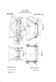
- FIG. 7 represents a locomotive ash pan divided into two hoppers 6 and 6 in the lower part thereof, to which are pivoted the doors 7 and 7 on the pivots 8 and'8 respectively.
- the revolved or open positions of these doors 7 and 7 being represented by 7 and 7 respectively.
- These doors 7 and 7 revolve about a horizontal axis onhthe pivots 8 and 8, on the sides of the hoppers 6 and 6 and do not come in contact with said hoppers at any other point, as will be seen from Figs.
- the hoppers. 6 and 6 are provided with cast metal frames 9' and 9 at the bottom of said hoppers.
- the doors 7 and 7 a are connected by parallel rods or links 10 on the pivots 11 and 11.
- the operating shaft;12,;t0 which are rigidly connected the crankarms 13 andthe endsthereof to prevent warping'or buckling operating lever 14, is supported by bearings I 15 which are rigidly connected to theloco motive frame. Between and connecting the I freeends of the crank arms 13 with pivots thereon tends to hold the operating arrangement in a locked position.
- This lock is eifected by so bending the rods 16 that 'a straight: line drawn through the centers of the two end connections thereof will pass well to the side of thecenter of the operating shaft 12, opposite to the rods 16.
- the latch 17 is only a safety appliance to prevent the operating arrangement from being thrown ofl of its locked position.
- the doors may, if desired, be operated by any other convenient means, instead of as shown on the accompanying drawing.
- My invention has been found in practice to enable the contents of large ash pans to bereadily discharged, and the mechanism employed insures the effective closure of the discharge openings, therebycpreventing the liability to dropping of hot cinders upon the right of way and eliminating the danger and lossby fire.
- I lkI'n a locomotive ash pan, the combination of an ash receptacle formed with a discharge opening in its lower portion, a dumpable closure for said receptacleadapted to cooperate with the discharge opening of the receptacle, said dumpableclosure bein adapted to retain an air sealing medium, an to form in connection with said receptacle an air seal, and means for operating said closure.
- a locomotive ash pan the combination of an ash receptacle formed with a discharge opening in its lower portion, a dumpable closure for said receptacle formedfwith fupwardly extending flanges surrounding the lower portion of said receptacle and spaced therefrom, when said closure is in a closed position, said closure adapted to retain an air sealing. medium and to form in connection with said receptacle an air seal, and means for operating said closure, substantially as specified.
- closures adapted to retain an air sealing medium and to form in connection with said receptacle an air seal, and means for operating said closures, substantially as specified.
- a locomotive ash pan the combination of an ash receptacle formed with 'a plurality of discharge openings in its lower portion, a' plurality of dumpable closures for said receptacle, one closure for each opening, formed with upwardly extending flanges surrounding the lower portions of said receptacle, when said closures are in a closed position, said closures adapted to retain an air sealing medium and to form in connection with said receptacle an air seal.
- a locomotive ash pan In a locomotive ash pan, the combination of an ash receptacle formed with a discharge opening in its lower portion, a swinging closure for said receptacle formed with upwardly extending flanges surrounding the lower portion of said receptacle, when said closure is in a closed position, said closure adapted to retain an air sealing medium and to form inconnection with said receptacle an air seal, said closure being provided with supporting members in the form of arms rigidly attached thereto, said supporting' members being pivoted at their free ends to said receptacle, and means for operating said closure, substantially as specified.
- a locomotive ash pan the combination of an ash receptacle formed with a discharge opening in its lower portion, a dumpable closure for said receptacle formed with upwardly inclined end flanges and vertical side flanges surrounding the lower portion of said receptacle, when said closure is in a closed position, said closure adapted to retain an air sealing medium and to form in connection with said receptacle an air seal, and means for operating said closure, substantially as specified.
Landscapes
- Engineering & Computer Science (AREA)
- Mechanical Engineering (AREA)
- General Engineering & Computer Science (AREA)
- Closures For Containers (AREA)
Description
W. E. WINE.
ILOGOMOTIVE ASH PAN. 7 APPLICATION FILED MAR.19, 1909.
Patented May. 2, 1911.
. fication.
My invention relates to locomotive ash invention, Figure 1 is a side elevation show- .WILLIAM E. W NE, or WILMINGTON, NORTH CAROLINA.
I ocoMoTIvE ASH-PAN.
' Specification of Letters Patent.
Patented May 2, 1911.
Application filed March 19, 1909. Serial No. 484,380.
T 0 all who'rn t't may concern:
Be it known that 1, WILLIAM citizen. of the United States, residing at Wilmington, in the county of New Hanover and State of North Carolina,- have invented new and useful Improvements in Locomotive Ash-Pans, of which the following is. a specipans, and has particular reference to the ash discharge doors therefor.
In ash pans commonly appliedto locomotives theash" discharge doors do not completely close the discharge openings when the hoppers or doors become warped, or when the pins or pivoted connections in the supporting and operating mechanisms become worn. As a consequence of this, great damage and loss by fire often occurs from hot cinders loosing out on the right of way, also the pan is often damaged from recombustion'of-unconsumfibcoal, caused by the admission of air between the doors and the an. 1 p The objectof my invention is to construct a locomotive ash pan that will eliminate the necessity of accurately machined or adjusted parts, and-so that it may be easily opened or dumped and closed in such a manner as not to allow ashes or cinders to loose out along the right of way,.even though the pivoted f I finer ashes will settle to the bottom and pack connections become worn and the pan or doors warped. I p
A further object of my invention is to pro- 'duce a discharge door that will swing away from the discharge opening by gravity.
A still further object of my invention is to i provide means for preventing the entrance of air betweenthe pan and the door.
My invention therefore consistsof a door provided with flanges and adapted to close and seal an opening in the bottom of an ash pan hopper.
In the accompanying drawing, which illustrates the preferred embodiment'of my ing the ash pan and operating arrangement in full lines, the open position of the doors and corresponding position of the operating arrangement by dotted lines and the other parts of the locomotive by broken lines; Fig. 2 is a rear elevation; Fig. 3 is a section of E. Winn, a z
the door and hopper on line 3-3; Fig. 4 is a section of the door and hopper on line 4c4.-.
Similar characters designate like parts throughout the several figures of the drawj ing.
Referring now to the parts by number, 5
represents a locomotive ash pan divided into two hoppers 6 and 6 in the lower part thereof, to which are pivoted the doors 7 and 7 on the pivots 8 and'8 respectively. The revolved or open positions of these doors 7 and 7 being represented by 7 and 7 respectively. These doors 7 and 7 revolve about a horizontal axis onhthe pivots 8 and 8, on the sides of the hoppers 6 and 6 and do not come in contact with said hoppers at any other point, as will be seen from Figs. 3 and 4, thus leaving aspaee all j around between said door and the lower part of said hopperg On account of the space between said door and said hopper, any wear in the pivoted connections, distortion of the door or hopper from heat or other cause, 1 inaccuracies in manufacture, erection or. adjustment, will not prevent the proper closing or operating of the door; The edges of the doors being flanged upwardly around p the lower ends of the hoppers,- the ashes or cinders are prevented from escaping through the space between said door and said hopper.
It has been found practice that the in said space sulficiently to prevent the ingress of air, which would cause recombustion in the hopper and thereby damage the an. I I
It may be desirable in warm climates to allow the injector overflow to discharge into the ash pan, which by reason of the upward ,flanges around the lower ends of the. hop
pers,-will effect anair tight seal.
The hoppers. 6 and 6 are provided with cast metal frames 9' and 9 at the bottom of said hoppers.
The doors 7 and 7 a are connected by parallel rods or links 10 on the pivots 11 and 11. The operating shaft;12,;t0 which are rigidly connected the crankarms 13 andthe endsthereof to prevent warping'or buckling operating lever 14, is supported by bearings I 15 which are rigidly connected to theloco motive frame. Between and connecting the I freeends of the crank arms 13 with pivots thereon tends to hold the operating arrangement in a locked position.
This lock is eifected by so bending the rods 16 that 'a straight: line drawn through the centers of the two end connections thereof will pass well to the side of thecenter of the operating shaft 12, opposite to the rods 16.
The latch 17 is only a safety appliance to prevent the operating arrangement from being thrown ofl of its locked position.
The positions of the parts 10, 11, 11*, 13, 14, and 16, when the doors 7 and 7 are open, are represented by 10, 11', 11*, 13,14, and16 respectively.
The doors may, if desired, be operated by any other convenient means, instead of as shown on the accompanying drawing.
My invention has been found in practice to enable the contents of large ash pans to bereadily discharged, and the mechanism employed insures the effective closure of the discharge openings, therebycpreventing the liability to dropping of hot cinders upon the right of way and eliminating the danger and lossby fire.
Having thus describedmy invention, I aim in the appended claims to cover all 'modifications which do not involve a departure from its spirit and scope.
What I claim as new and desire to secure by'Letters Patent of'the United States is:
I lkI'n a locomotive ash pan, the combination of an ash receptacle formed with a discharge opening in its lower portion, a dumpable closure for said receptacleadapted to cooperate with the discharge opening of the receptacle, said dumpableclosure bein adapted to retain an air sealing medium, an to form in connection with said receptacle an air seal, and means for operating said closure.
2. In a locomotive'ash pan, the combination of an ash receptacle formed with a discharge opening in its lower portion, a dumpable closure for said receptacle formed with upwardly extending flanges surrounding the to .form in connection with said receptacle an air seal, and means for operating said closure, substantially as specified.
3. In a locomotive ash pan, the combination of an ash receptacle formed with a discharge opening in its lower portion, a dumpable closure for said receptacle formedfwith fupwardly extending flanges surrounding the lower portion of said receptacle and spaced therefrom, when said closure is in a closed position, said closure adapted to retain an air sealing. medium and to form in connection with said receptacle an air seal, and means for operating said closure, substantially as specified.
4:. In a locomotive ash pan, the combination of an ash receptacle formed with a discharge opening in its lower portion, a plurality of dumpable closures for said receptacle formed with upwardly extending'flanges surrounding the lower portion of said receptacle when said closures are in a closed.
position, said closures adapted to retain an air sealing medium and to form in connection with said receptacle an air seal, and means for operating said closures, substantially as specified.
5.-In a locomotive ash pan, the combination of an ash receptacle formed with 'a plurality of discharge openings in its lower portion, a' plurality of dumpable closures for said receptacle, one closure for each opening, formed with upwardly extending flanges surrounding the lower portions of said receptacle, when said closures are in a closed position, said closures adapted to retain an air sealing medium and to form in connection with said receptacle an air seal.
-6.. In a locomotive ash pan, the combination of an ash receptacle formed with a discharge opening in its lower portion, a swinging closure for said receptacle formed with upwardly extending flanges surrounding the lower portion of said receptacle, when said closure is in a closed position, said closure adapted to retain an air sealing medium and to form inconnection with said receptacle an air seal, said closure being provided with supporting members in the form of arms rigidly attached thereto, said supporting' members being pivoted at their free ends to said receptacle, and means for operating said closure, substantially as specified. Y
7 In a locomotive ash pan, the combination of an ash receptacle formed with a discharge opening in its lower portion, a dumpable closure for said receptacle formed with upwardly inclined end flanges and vertical side flanges surrounding the lower portion of said receptacle, when said closure is in a closed position, said closure adapted to retain an air sealing medium and to form in connection with said receptacle an air seal, and means for operating said closure, substantially as specified.
-8. In a locomotive ash an, the combination of an ash receptacle ormed with a discharge opening in its lower portion, a swinging closure for said receptacle formed withsaid closure being provided with supporting In witness whereof I have hereunto set I members integral with said side flanges arlld my hand this 15th day of March 1909. pivoted at their top ends to said receptac e y the pivotal axis being so located that said WILLIAM closure will swing from said receptacle by Witnesses: gravity, and means for operating said 010- Gnonen G. THOMAS, J11, sure, substantially as specified. GUY R. DAVIS.
Copies 0: this patent may-be obtained for five cents each, by addressing the Commissioner of Patents,
Washington, D. G.
Priority Applications (1)
| Application Number | Priority Date | Filing Date | Title |
|---|---|---|---|
| US48438009A US991257A (en) | 1909-03-19 | 1909-03-19 | Locomotive ash-pan. |
Applications Claiming Priority (1)
| Application Number | Priority Date | Filing Date | Title |
|---|---|---|---|
| US48438009A US991257A (en) | 1909-03-19 | 1909-03-19 | Locomotive ash-pan. |
Publications (1)
| Publication Number | Publication Date |
|---|---|
| US991257A true US991257A (en) | 1911-05-02 |
Family
ID=3059593
Family Applications (1)
| Application Number | Title | Priority Date | Filing Date |
|---|---|---|---|
| US48438009A Expired - Lifetime US991257A (en) | 1909-03-19 | 1909-03-19 | Locomotive ash-pan. |
Country Status (1)
| Country | Link |
|---|---|
| US (1) | US991257A (en) |
-
1909
- 1909-03-19 US US48438009A patent/US991257A/en not_active Expired - Lifetime
Similar Documents
| Publication | Publication Date | Title |
|---|---|---|
| US991257A (en) | Locomotive ash-pan. | |
| US642161A (en) | Valve for chutes. | |
| US904756A (en) | Ash-scoop. | |
| US944317A (en) | Attachment for stoves. | |
| US754135A (en) | Heating-tank. | |
| US938824A (en) | Locomotive ash-pan | |
| US1226511A (en) | Refuse-receptacle. | |
| US949017A (en) | Locomotive ash-pan. | |
| US1530787A (en) | Feed door for garbage incinerators | |
| US1169302A (en) | Wall garbage-receptacle. | |
| US574336A (en) | Stove or range | |
| US436352A (en) | Ash-sifter | |
| US231625A (en) | Damper for cooking-stoves | |
| US929265A (en) | Radial door. | |
| US918210A (en) | Ventilator for skylights. | |
| US941815A (en) | Locomotive ash-pan. | |
| US1040084A (en) | Ventilating-shutter. | |
| US1038987A (en) | Locomotive ash-pan. | |
| US649535A (en) | Journal-box. | |
| US934269A (en) | Drop-door-operating mechanism for hopper-bottom cars. | |
| US1130411A (en) | Feeding and stoking attachment for furnaces. | |
| US198359A (en) | Improvement in carts for heating and conveying plastic composition | |
| US804412A (en) | Dumping-car. | |
| US413386A (en) | Edward | |
| US255783A (en) | Flue-cap for stove-pipes |