US9909751B2 - Heat sink for lighting device - Google Patents
Heat sink for lighting device Download PDFInfo
- Publication number
- US9909751B2 US9909751B2 US15/109,813 US201515109813A US9909751B2 US 9909751 B2 US9909751 B2 US 9909751B2 US 201515109813 A US201515109813 A US 201515109813A US 9909751 B2 US9909751 B2 US 9909751B2
- Authority
- US
- United States
- Prior art keywords
- lighting device
- cylindrical case
- heat
- heat sink
- outer case
- Prior art date
- Legal status (The legal status is an assumption and is not a legal conclusion. Google has not performed a legal analysis and makes no representation as to the accuracy of the status listed.)
- Active
Links
Images


Classifications
-
- F—MECHANICAL ENGINEERING; LIGHTING; HEATING; WEAPONS; BLASTING
- F21—LIGHTING
- F21V—FUNCTIONAL FEATURES OR DETAILS OF LIGHTING DEVICES OR SYSTEMS THEREOF; STRUCTURAL COMBINATIONS OF LIGHTING DEVICES WITH OTHER ARTICLES, NOT OTHERWISE PROVIDED FOR
- F21V29/00—Protecting lighting devices from thermal damage; Cooling or heating arrangements specially adapted for lighting devices or systems
- F21V29/50—Cooling arrangements
- F21V29/51—Cooling arrangements using condensation or evaporation of a fluid, e.g. heat pipes
-
- F—MECHANICAL ENGINEERING; LIGHTING; HEATING; WEAPONS; BLASTING
- F21—LIGHTING
- F21V—FUNCTIONAL FEATURES OR DETAILS OF LIGHTING DEVICES OR SYSTEMS THEREOF; STRUCTURAL COMBINATIONS OF LIGHTING DEVICES WITH OTHER ARTICLES, NOT OTHERWISE PROVIDED FOR
- F21V15/00—Protecting lighting devices from damage
- F21V15/01—Housings, e.g. material or assembling of housing parts
-
- F—MECHANICAL ENGINEERING; LIGHTING; HEATING; WEAPONS; BLASTING
- F21—LIGHTING
- F21V—FUNCTIONAL FEATURES OR DETAILS OF LIGHTING DEVICES OR SYSTEMS THEREOF; STRUCTURAL COMBINATIONS OF LIGHTING DEVICES WITH OTHER ARTICLES, NOT OTHERWISE PROVIDED FOR
- F21V17/00—Fastening of component parts of lighting devices, e.g. shades, globes, refractors, reflectors, filters, screens, grids or protective cages
- F21V17/10—Fastening of component parts of lighting devices, e.g. shades, globes, refractors, reflectors, filters, screens, grids or protective cages characterised by specific fastening means or way of fastening
- F21V17/104—Fastening of component parts of lighting devices, e.g. shades, globes, refractors, reflectors, filters, screens, grids or protective cages characterised by specific fastening means or way of fastening using feather joints, e.g. tongues and grooves, with or without friction
-
- F—MECHANICAL ENGINEERING; LIGHTING; HEATING; WEAPONS; BLASTING
- F21—LIGHTING
- F21V—FUNCTIONAL FEATURES OR DETAILS OF LIGHTING DEVICES OR SYSTEMS THEREOF; STRUCTURAL COMBINATIONS OF LIGHTING DEVICES WITH OTHER ARTICLES, NOT OTHERWISE PROVIDED FOR
- F21V29/00—Protecting lighting devices from thermal damage; Cooling or heating arrangements specially adapted for lighting devices or systems
- F21V29/50—Cooling arrangements
- F21V29/70—Cooling arrangements characterised by passive heat-dissipating elements, e.g. heat-sinks
- F21V29/74—Cooling arrangements characterised by passive heat-dissipating elements, e.g. heat-sinks with fins or blades
- F21V29/77—Cooling arrangements characterised by passive heat-dissipating elements, e.g. heat-sinks with fins or blades with essentially identical diverging planar fins or blades, e.g. with fan-like or star-like cross-section
- F21V29/773—Cooling arrangements characterised by passive heat-dissipating elements, e.g. heat-sinks with fins or blades with essentially identical diverging planar fins or blades, e.g. with fan-like or star-like cross-section the planes containing the fins or blades having the direction of the light emitting axis
-
- F—MECHANICAL ENGINEERING; LIGHTING; HEATING; WEAPONS; BLASTING
- F21—LIGHTING
- F21V—FUNCTIONAL FEATURES OR DETAILS OF LIGHTING DEVICES OR SYSTEMS THEREOF; STRUCTURAL COMBINATIONS OF LIGHTING DEVICES WITH OTHER ARTICLES, NOT OTHERWISE PROVIDED FOR
- F21V31/00—Gas-tight or water-tight arrangements
- F21V31/005—Sealing arrangements therefor
-
- F—MECHANICAL ENGINEERING; LIGHTING; HEATING; WEAPONS; BLASTING
- F21—LIGHTING
- F21V—FUNCTIONAL FEATURES OR DETAILS OF LIGHTING DEVICES OR SYSTEMS THEREOF; STRUCTURAL COMBINATIONS OF LIGHTING DEVICES WITH OTHER ARTICLES, NOT OTHERWISE PROVIDED FOR
- F21V7/00—Reflectors for light sources
- F21V7/0066—Reflectors for light sources specially adapted to cooperate with point like light sources; specially adapted to cooperate with light sources the shape of which is unspecified
-
- F—MECHANICAL ENGINEERING; LIGHTING; HEATING; WEAPONS; BLASTING
- F21—LIGHTING
- F21V—FUNCTIONAL FEATURES OR DETAILS OF LIGHTING DEVICES OR SYSTEMS THEREOF; STRUCTURAL COMBINATIONS OF LIGHTING DEVICES WITH OTHER ARTICLES, NOT OTHERWISE PROVIDED FOR
- F21V7/00—Reflectors for light sources
- F21V7/22—Reflectors for light sources characterised by materials, surface treatments or coatings, e.g. dichroic reflectors
-
- F—MECHANICAL ENGINEERING; LIGHTING; HEATING; WEAPONS; BLASTING
- F21—LIGHTING
- F21Y—INDEXING SCHEME ASSOCIATED WITH SUBCLASSES F21K, F21L, F21S and F21V, RELATING TO THE FORM OR THE KIND OF THE LIGHT SOURCES OR OF THE COLOUR OF THE LIGHT EMITTED
- F21Y2115/00—Light-generating elements of semiconductor light sources
- F21Y2115/10—Light-emitting diodes [LED]
Definitions
- the present invention relates to a heat sink for a lighting device that radiates the heat generated from the lighting device to cool the lighting device.
- a lighting device generates light therefrom and collects the generated light thereto to emit the light in one direction.
- the lighting device includes a fluorescent light, an incandescent light, a halogen light, a mercury light, a sodium light, a metal light or the like.
- an LED Light Emitting Diode
- the LED is an optoelectronic device which has a bonding structure of p-type and n-type semiconductors to allow electrons and holes to be bonded to each other upon application of power to emit the light of energy corresponding to the band gap of the semiconductors therefrom.
- the LED has relatively low power consumption, semi-permanent life span, low fatigue in optic nerves, and various colors, and accordingly, the LED has been recently used for indoor and outdoor lighting.
- the brightness of the LED is proportional to the strength of electric current applied to the LED.
- the strength of electric current is increased to raise the brightness of the LED
- the strength of heat generated from the LED is also increased to cause the LED to be damaged due to the heat, thereby undesirably shortening the life span of the LED.
- Korean Patent No. 10-1142936 (dated on May 10, 2012) entitled “light emitting device”.
- the conventional light emitting device includes a substrate having a heat pipe, an insulation film disposed on the substrate, electrode terminals located on the insulation film, and an LED package mounted on the electrode terminals, wherein the substrate having the heat pipe includes a body having at least one empty internal space, an operating fluid injected into the empty internal space, and a wick disposed on the inner peripheral wall of the empty internal space.
- the LED package or a light emitting chip is mounted on the substrate having the heat pipe, and the heat generated from the LED package or the light emitting chip is radiated to the outside, thereby cooling the LED package or the light emitting chip.
- the substrate having the heat pipe itself absorbs the heat generated from the LED package to cause the heat to be increased locally, thereby undesirably resulting in the malfunction of the LED package.
- the substrate having the heat pipe has a shape of a simple container plate to cause the returning passage of the operating fluid to be extended further, so that the circulation of heat through the operating fluid is not gently achieved, thereby undesirably failing to efficiently radiate the heat.
- the present invention has been made in view of the above-mentioned problems occurring in the prior art, and it is an object of the present invention to provide a heat sink for a lighting device that is capable of improving the heat radiation effects of the lighting device radiating high luminance light therefrom to efficiently cool an LED module.
- a heat sink for a lighting device which radiates the heat generated from the lighting device, including: an outer case coupled to the lighting device; an inner case accommodated into the outer case in such a manner as to be spaced apart therefrom to form a filling space between the inner case and the outer case; and a cooling medium vaporized on a portion of the outer case coupled to the lighting device by means of the heat generated from the lighting device to cool the lighting device.
- capillary protrusions are formed protrudingly from any one of the inner peripheral surface of the outer case and the outer peripheral surface of the inner case or both of the inner peripheral surface of the outer case and the outer peripheral surface of the inner case to reduce the filling space so that the cooling medium is dispersed to the filling space through the capillary phenomenon of the capillary protrusions.
- the outer case has heat radiation fins protruding from the outer peripheral surface thereof to enlarge the surface area thereof.
- one pair of heat radiation fins constitutes one set so that a plurality of heat radiation fin sets protrudes from the outer peripheral surface of the outer case, and the outer case has heat radiation plates fitted to each pair of heat radiation fins to perform the heat exchange with the outside of the outer case.
- a sealing cover is located between the inner case and the outer case to seal the filling space.
- the sealing cover is made of an insulation material to prevent the heat of the outer case from being transmitted to the inner case.
- the outer case has medium dispersion passages formed on the inner surface of the portion coupled to the lighting device to disperse the cooling medium of liquid phase therealong.
- the inner case has an accommodation space adapted to accommodate a power supplier for supplying power to the lighting device thereinto and a cap adapted to close the accommodation space.
- the lighting device is an LED module.
- the LED module includes: an LED lamp coupled to the outer case to emit the light therefrom; a reflection plate adapted to reflect the light around the LED lamp in a radiation direction of the light of the LED lamp; a guider adapted to surroundingly protect the LED lamp; a lens seated on the guider to collect the light emitted from the LED lamp thereto; and a packing adapted to seal the space between the guider and the lens.
- the heat sink for the lighting device is configured wherein the medium dispersion passages serve to improve the vaporization speed of the cooling medium to prevent the heat generated from the LED module from being raised locally to the outer case, thereby improving the heat radiation effects.
- the heat sink for the lighting device is configured wherein the cooling medium is rapidly dispersed to the filling space by means of the capillary protrusions so that it may be dispersed uniformly to the entire portion of the filling space and further circulated gently, thereby allowing the heat generated from the LED module to be rapidly and uniformly cooled on the entire portion of the outer case.
- the heat sink for the lighting device is configured wherein the heat radiation fins serve to increase the area contacted with the external air, thereby improving the heat radiation effects.
- FIG. 1 is a perspective view showing a heat sink for a lighting device according to the present invention.
- FIG. 2 is a sectional view showing the heat sink for a lighting device according to the present invention.
- FIG. 3 is a partially cut-off perspective view showing the heat sink for a lighting device according to the present invention.
- FIG. 4 is a sectional view showing a lighting device-coupling part of an outer case in the heat sink for a lighting device according to the present invention.
- FIG. 5 is an enlarged view showing a filling space of the heat sink for a lighting device according to the present invention.
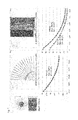
- FIGS. 6 and 7 are graphs showing the comparison test results of heat distribution according to distances from an LED module so as to testify the heat radiation effects of the heat sink for a lighting device according to the present invention.
- heat sink for lighting device 200 outer case 210: lighting device-coupling part 220: medium dispersion passage 230: heat radiation fin 240: coupling groove 250: heat radiation plate 260: LED module 261: LED lamp 262: reflection plate 263: guider 264: lens 265: packing 270: capillary protrusion 300: inner case 310: accommodation space 320: filling space 330: cap 340: sealing cover 341: coupling part 342: locking part 400: cooling medium Mode for Invention
- a lighting device is adapted to generate light therefrom, collect the generated light thereto, and radiate the light therefrom.
- the lighting device includes all kinds of lights such as fluorescent lights, incandescent lights, halogen lights, mercury lights, sodium lights, metal lights and the like, while being not limited specifically thereto.
- the lighting device adopted in the present invention is an LED module 260 .
- a heat sink 100 for a lighting device includes an outer case 200 .
- the outer case 200 has a shape of a container empty in the interior thereof and having closed one end and includes a lighting device-coupling part 210 and a side wall part 215 .
- the side wall part 215 has a shape of a casing whose interior is empty and is closed on one end thereof by means of the lighting device-coupling part 210 , so that the entire shape of the outer case 200 looks like a container.
- the lighting device-coupling part 210 has a shape of a plate and is coupled to the lighting device on the outer surface thereof by means of fastening members like bolts, so that the heat generated from the lighting device is transmitted entirely to the outer case 200 .
- the lighting device-coupling part 210 has grooves formed correspondingly to the edges of the portion to which the lighting device is coupled, thereby allowing the lighting device to be press-fitted to the lighting device-coupling part 210 .
- thermal grease is applied between the lighting device-coupling part 210 and the lighting device so as to enhance a degree of contact between them coupled to each other.
- the side wall part 215 has a shape of the casing empty in the interior thereof to the form of a variety of shapes such as a rectangle, a triangle and so on.
- the outer case 215 is made of a metal having high thermal conductivity such as aluminum, copper, gold and their alloys so as to rapidly transmit the heat generated from the lighting device to the outer case 200 .
- the lighting device-coupling part 210 has medium dispersion passages 220 .
- the medium dispersion passages 220 are formed on the inner surface of the lighting device-coupling part 210 , that is, on the opposite surface to the surface to which the lighting device is coupled, thereby preventing the temperature of the outer case 200 from being raised locally by the heat generated from the LED module 260 (See FIG. 4 ).
- the medium dispersion passages 220 have the shape of a plurality of grooves formed on the lighting device-coupling part 210 , so that a cooling medium 400 as will be discussed later is dispersed entirely to the lighting device-coupling part 210 therealong.
- the outer case 200 includes a plurality of heat radiation fins 230 .
- One pair of heat radiation fins 230 constitutes one set so as to enlarge the surface area of the outer case 200 . Accordingly, a plurality of heat radiation fin sets 230 protrudes radially from the outer periphery of the outer case 200 .
- heat radiation fins 230 are extended in a longitudinal direction of the outer case 200 , and heat radiation plates 250 as will be discussed later are fitted to the heat radiation fins 230 .
- each heat radiation plate 250 is fitted to a coupling groove 240 formed between each pair of heat radiation fins 230 , so that the heat radiation plates 250 are coupled to the outer case 200 .
- the outer case 200 has the heat radiation plates 250 .
- the heat radiation plates 250 have shapes of plates of given thickness coupled to the coupling grooves 240 so as to transfer the heat transmitted to the outer case 200 to the outside, that is, to exchange the heat transmitted to the outer case 200 with the air in the space in which the heat sink 100 is mounted.
- the lengths of the heat radiation plates 250 are extended outwardly from the outer case 200 , the surface areas of the heat radiation plates 250 become enlarged, thereby improving the heat radiation effects thereof, but if so, the weights and sizes of the heat radiation plates 250 are increased to cause low portability.
- the lengths of the heat radiation plates 250 are not longer than a diameter of the outer case 200 .
- the heat radiation plates 250 are made of a metal having high thermal conductivity such as aluminum, copper, gold and their alloys so as to rapidly transmit the heat generated from the heat radiation fins 230 thereto.
- the heat sink 100 for a lighting device according to the present invention includes an inner case 300 .
- the inner case 300 is accommodated into the outer case 200 in such a manner as to be spaced apart therefrom to form a filling space 320 between the inner case 300 and the outer case 200 , and the cooling medium 400 is filled into the filling space 320 .
- the inner case 300 has a shape of a container whose one surface is open to form an accommodation space 310 therein to accommodate a power supplier (not shown) for supplying power to the lighting device thereinto.
- the heat sink 100 for a lighting device according to the present invention includes the cooling medium 400 .
- the cooling medium 400 is filled into the filling space 320 so as to cool the outer case 200 coupled to the lighting device.
- the cooling medium 400 has a phase change from liquid to gas through the heat of the lighting device-coupling part 210 transmitted from the lighting device and thus cools the outer case 200 , thereby improving the cooling efficiency of the lighting device.
- the cooling medium 400 of the liquid state is heated and vaporized on a portion of the outer case 200 , that is, on the lighting device-coupling part 210 to which the lighting device is coupled, by means of the heat generated from the lighting device.
- the cooling medium 400 As the cooling medium 400 is vaporized, at this time, it radiates the surrounding heat, thereby cooling the lighting device.
- the vaporized cooling medium 400 is liquefied on a portion of the filling space 320 whose temperature is lowered through the heat exchange with the outside on the heat radiation plates 250 and the outer case 200 .
- the vaporized cooling medium 400 is liquefied on an upper portion of the filling space 320 spaced from the lighting device and is circulated again to the lighting device-coupling part 210 , thereby cooling the lighting device efficiently.
- the cooling medium 400 includes a cooling medium having a relatively low temperature difference in phase change, such as water, alcohol, alkaline solution and so on.
- the heat sink 100 for a lighting device according to the present invention includes capillary protrusions 270 .
- the capillary protrusions 270 are adapted to reduce the distance between the outer case 200 and the inner case 300 so as to allow the cooling medium 400 to be dispersed to the entire portion of the filling space 320 through capillary phenomenon.
- the capillary protrusions 270 are formed protrudingly from the inner peripheral surface of the outer case 200 toward the inner case 300 , from the outer peripheral surface of the inner case 300 toward the outer case 200 , or from the corresponding positions between the inner peripheral surface of the outer case 200 and the outer peripheral surface of the inner case 300 .
- the capillary protrusions 270 are extended longer toward a direction in which the lighting device-coupling part 210 is located so as to guide the liquid phase cooling medium 400 therealong and supply it to the lighting device-coupling part 210 , and otherwise, the capillary protrusions 270 protrude from the outer peripheral surface of the inner case 300 , the inner peripheral surface of the outer case 200 , or the outer and inner peripheral surfaces of both of the inner case 300 and the outer case 200 .
- cooling medium 400 moves to the gap reduced by means of the capillary protrusions 270 under the capillary phenomenon, it is dispersed to the entire portion of the filling space 320 , thereby cooling the entire portion of the filling space 320 uniformly.
- the heat sink 100 for a lighting device according to the present invention includes a sealing cover 340 .
- the sealing cover 340 is adapted to close the end of the outer case 200 and the end of the inner case 300 so as to allow the filling space 320 to be sealed between the outer case 200 and the inner case 300 to prevent the cooling medium 400 from being discharged to the outside or prevent the external air from being introduced into the filling space 320 .
- the sealing cover 340 is made of an elastic material for improving the sealing force of the filling space 320 , for example, rubber, urethane, silicone and the like, and has a shape of a ring.
- the sealing cover 340 includes a coupling part 341 and a locking part 342 .
- the coupling part 341 has a corresponding shape to the sectional shape of the filling space 320 so as to allow the sealing cover 340 to be press-fitted to the end of the space between the inner case 300 and the outer case 200 to seal the filling space 320 .
- the locking part 342 is formed along the top of the coupling part 341 and has a larger periphery than the periphery of the coupling part 341 in such a manner as to be locked onto the end of the space between the inner case 300 and the outer case 200 .
- the heat sink 100 for a lighting device according to the present invention includes a cap 330 .
- the cap 330 is adapted to seal the end of the inner case 300 to close the accommodation space 310 formed in the inner case 300 and at the same time to prevent the sealing cover 340 from being escaped from the inner case 300 and the outer case 200 .
- the cap 330 is coupled to the end periphery of the outer case 200 by means of fastening members like bolts.
- the heat sink 100 for a lighting device includes an LED module 260 .
- the LED module 260 is coupled to the outer case 200 , that is, to the lighting device-coupling part 210 to radiate light therefrom.
- the LED module 260 includes an LED lamp 261 , a reflection plate 262 , a guider 263 , a lens 264 , and a packing 265 .
- the LED lamp 261 is mounted on a substrate (not shown) electrically connected thereto to emit light therefrom, so that the LED lamp 261 mounted on the substrate is surface-contacted with the lighting device-coupling part 210 .
- LED lamp 261 In addition to the LED lamp 261 , further, electric elements for controlling the LED lamp 261 , for example, condensers, resistors, transistors and so on are mounted on the substrate.
- condensers, resistors, transistors and so on are mounted on the substrate.
- the reflection plate 262 surrounds the edges of the LED lamp 261 in such a manner as to allow the LED lamp 261 to be located at the inside thereof and reflects the light around the LED lamp 261 in a radiation direction of the light of the LED lamp 261 .
- the reflection plate 262 is made of a metal plate having a silver color capable of reflecting the light of the LED lamp 261 , and otherwise, the reflection plate 262 is formed by applying a reflection material such as paints, metal materials and so on thereto.
- the guider 263 has a shape of a ring surroundingly protecting the LED lamp 261 so as to seat the lens 264 as will be discussed later on the LED lamp 261 .
- the lens 264 is seated on the guider 263 , is fixed to the LED lamp 261 , and collects the light emitted from the LED lamp 261 so as to farther emit the light of the LED lamp 261 .
- the lens 264 is a convex lens capable of collecting light thereto and may include different kinds of lenses laid on each other.
- the packing 265 has a shape of a ring and is located between the guider 263 and the lens 264 to seal the space between the guider 263 and the lens 264 .
- the packing 265 is made of an elastic material such as synthetic rubber, natural rubber, synthetic resin, urethane, silicone and so on.
- the heat radiation plates 250 are coupled to the coupling grooves 240 of the heat radiation fins 230 so as to transfer the heat transmitted to the outer case 200 to the outside.
- the inner case 300 is accommodated into the outer case 200 in such a manner as to be spaced apart therefrom, and the power supplier is accommodated into the accommodation space 310 of the inner case 300 so as to supply power to the LED module 260 .
- the plurality of heat radiation fin sets 230 are formed on the outer peripheral surface of the outer case 200 , and each heat radiation plate 250 is coupled to each pair of the heat radiation fins 230 .
- the cooling medium 400 is filled into the filling space 320 .
- the cooling medium 400 is filled in the state where the filling space 320 is vacuumed so that the phase change of the cooling medium 400 occurs dynamically.
- the coupling part 341 of the sealing cover 340 is located at the space between the end of the outer case 200 and the end of the inner case 300 so as to seal the filling space 320 therewith.
- the cap 330 is coupled to the end of the inner case 300 to completely close the accommodation space 310 .
- a portion of the LED module 260 where the heat is most generated is surface-contacted with the outer surface of the lighting device-coupling part 210 , and accordingly, the LED module 260 is electrically connected to the power supplier so as to receive the power from the power supplier accommodated in the internal space of the inner case 300 .
- the LED lamp 261 radiates light therefrom and at the same time generates heat therefrom according to the characteristics thereof.
- the heat is transmitted to the lighting device-coupling part 210 of the outer case 200 , and accordingly, the cooling medium 400 is heated and vaporized by means of the heat transmitted to the lighting device-coupling part 210 .
- the cooling medium 400 of the liquid phase is dispersed uniformly on the opposite surface to the surface to which the LED lamp 261 is coupled by means of the medium dispersion passages 220 and thus phase-changed.
- the cooling medium 400 is dispersed uniformly by means of the medium dispersion passages 220 to prevent the heat generated from the LED lamp 261 from being collected to the lighting device-coupling part 210 as a portion of the outer case 200 and to rapidly transfer the vaporized cooling medium 400 to the filling space 320 , thereby improving the cooling efficiency.
- the heat the cooling medium 400 has had is exchanged with the heat of the outer case 200 and the inner case 300 on the portion wherein the capillary protrusions 270 are not formed on the inner peripheral surface of the outer case 200 and on the outer peripheral surface of the inner case 300 , so that the cooling medium 400 of the gas state is changed to the liquid state.
- the cooling medium 400 phase-changed to the liquid state moves to the adjacent capillary protrusions 270 to each other by means of the capillary phenomenon, so that the cooling medium 400 is dispersed uniformly to the entire portion of the filling space 320 , thereby allowing the heat generated from the LED module 260 to be uniformly dispersed and at the same time rapidly cooled.
- the heat transferred to the outer case 200 is transmitted to the heat radiation plates 250 through the heat radiation fins 230 of the outer case 200 and thus exchanged with the external air on the heat radiation plates 250 , thereby cooling the outer case 200 .
- FIG. 6 shows a comparison example in which a heat sink has a convex-shaped body having the same size as the outer case 200 of the heat sink according to the present invention and heat radiation plates having the same sizes as those according to the present invention
- FIG. 7 shows the heat sink 100 according to the present invention.
- the x-axis indicates the distance from the LED module 260 in the unit of meter m and the y-axis indicates a temperature in the unit of Celsius ° C.
- the heat sink according to the comparison example shows that the heat generated from the LED module 260 is gradually lowered toward the circumferential direction of the LED module 260 from the center thereof so that the efficiency of the heat sink toward the outer periphery of the upper portion thereof becomes low, thereby undesirably reducing the heat radiation effects thereof.
- the heat sink 100 according to the present invention shows that there are only temperature differences according to the distances from the LED module 260 and the heat radiation effects are provided uniformly in upward and downward directions thereof so that the heat sink 100 according to the present invention can obtain more excellent heat radiation effects than the heat sink according to the comparison example.
- FIG. 7 is a graph showing the heat distribution test results of the heat sink 100 according to the present invention, and as shown in FIG. 7 , the heat generated from the LED module 260 is prevented from being raised locally on the outer case 200 and the heat radiation plates 250 , thereby allowing the heat to be distributed uniformly to the outer case 200 and the heat radiation plates 250 .
- the medium dispersion passages 220 serve to improve the vaporization speed of the cooling medium 400 so that the heat generated from the LED module 260 is prevented from being raised locally on the outer case 200 , thereby improving the heat radiation effects.
- the cooling medium 400 is rapidly dispersed to the filling space 320 by means of the capillary protrusions 270 so that it may be dispersed uniformly to the entire portion of the filling space 320 and further circulated gently, thereby allowing the heat generated from the LED module 260 to be rapidly and uniformly cooled on the entire portion of the outer case 200 .
- the heat radiation fins 230 serve to increase the area contacted with the external air, thereby improving the heat radiation effects.
- the present invention is useful in various industrial fields for heat radiation of all kinds of lighting fixtures and heat radiation appliances.
Landscapes
- Engineering & Computer Science (AREA)
- General Engineering & Computer Science (AREA)
- Arrangement Of Elements, Cooling, Sealing, Or The Like Of Lighting Devices (AREA)
Applications Claiming Priority (3)
| Application Number | Priority Date | Filing Date | Title |
|---|---|---|---|
| KR10-2014-0001039 | 2014-01-06 | ||
| KR1020140001039A KR101674673B1 (ko) | 2014-01-06 | 2014-01-06 | 조명용 방열장치 |
| PCT/KR2015/000008 WO2015102422A1 (fr) | 2014-01-06 | 2015-01-02 | Dissipateur thermique pour lumière |
Publications (2)
| Publication Number | Publication Date |
|---|---|
| US20160320043A1 US20160320043A1 (en) | 2016-11-03 |
| US9909751B2 true US9909751B2 (en) | 2018-03-06 |
Family
ID=53493690
Family Applications (1)
| Application Number | Title | Priority Date | Filing Date |
|---|---|---|---|
| US15/109,813 Active US9909751B2 (en) | 2014-01-06 | 2015-01-02 | Heat sink for lighting device |
Country Status (5)
| Country | Link |
|---|---|
| US (1) | US9909751B2 (fr) |
| EP (1) | EP3096080A4 (fr) |
| KR (1) | KR101674673B1 (fr) |
| CN (1) | CN106062477A (fr) |
| WO (1) | WO2015102422A1 (fr) |
Families Citing this family (4)
| Publication number | Priority date | Publication date | Assignee | Title |
|---|---|---|---|---|
| KR101959327B1 (ko) * | 2017-05-31 | 2019-03-18 | 황윤철 | 바닥 냉난방 장치 |
| CN108775566A (zh) * | 2018-06-09 | 2018-11-09 | 江苏泓睿德智能科技有限公司 | 一种led灯散热器 |
| CN108716659A (zh) * | 2018-06-09 | 2018-10-30 | 江苏泓睿德智能科技有限公司 | 一种大功率led灯散热装置 |
| KR102416269B1 (ko) * | 2021-12-23 | 2022-07-06 | (주)삼백테크놀로지 | 상변화물질이 포함된 엘이디 조명모듈 |
Citations (11)
| Publication number | Priority date | Publication date | Assignee | Title |
|---|---|---|---|---|
| KR20090077120A (ko) | 2008-01-10 | 2009-07-15 | 김종희 | 컵형상 히트 스프레더 및 이를 이용한 led모듈용냉각장치 |
| KR20100127971A (ko) | 2009-05-27 | 2010-12-07 | 지엘레페주식회사 | 엘이디 조명등용 히트 스프레더 유니트 및 이를 이용한 엘이디 조명등용 히트 스프레더 |
| US20110044038A1 (en) * | 2009-08-18 | 2011-02-24 | Fu Zhun Precision Industry (Shen Zhen) Co., Ltd. | Led lamp |
| KR20110069226A (ko) | 2009-12-17 | 2011-06-23 | 티티엠주식회사 | 엘이디 램프 |
| US20110169391A1 (en) * | 2010-01-13 | 2011-07-14 | Fu Zhun Precision Industry (Shen Zhen) Co., Ltd. | Led lamp |
| US20120008329A1 (en) * | 2010-07-06 | 2012-01-12 | Leader Trend Technology Corp. | Led street lamp |
| KR20120024860A (ko) | 2009-05-28 | 2012-03-14 | 코닌클리즈케 필립스 일렉트로닉스 엔.브이. | 광원을 둘러싸는 봉입체를 갖는 조명 장치 |
| KR101142936B1 (ko) | 2004-12-31 | 2012-05-10 | 서울반도체 주식회사 | 발광 장치 |
| US20130163247A1 (en) | 2011-12-21 | 2013-06-27 | Lite-On Technology Corp. | Lamp base and lamp having the same |
| US20130223064A1 (en) * | 2012-02-27 | 2013-08-29 | Zhongshan Weiqiang Technology Co., Ltd. | Led projection lamp |
| KR20130116589A (ko) | 2012-04-16 | 2013-10-24 | 김용길 | 방열장치 및 방열장치의 제조방법 |
Family Cites Families (5)
| Publication number | Priority date | Publication date | Assignee | Title |
|---|---|---|---|---|
| US8196643B2 (en) * | 2009-01-20 | 2012-06-12 | Shyh Ming Chen | Ring heat dissipating device formed by punching and riveting through a shaping mold |
| CN101825235A (zh) * | 2009-03-05 | 2010-09-08 | 富准精密工业(深圳)有限公司 | 发光二极管灯具及其光引擎 |
| KR20110069225A (ko) * | 2009-12-17 | 2011-06-23 | 티티엠주식회사 | 엘이디 램프 |
| CN102235615A (zh) * | 2010-04-21 | 2011-11-09 | 中国科学院工程热物理研究所 | 一种腔式发光二极管灯 |
| KR20120080022A (ko) * | 2011-01-06 | 2012-07-16 | 삼성엘이디 주식회사 | 조명 장치 |
-
2014
- 2014-01-06 KR KR1020140001039A patent/KR101674673B1/ko active Active
-
2015
- 2015-01-02 WO PCT/KR2015/000008 patent/WO2015102422A1/fr not_active Ceased
- 2015-01-02 EP EP15733238.8A patent/EP3096080A4/fr not_active Withdrawn
- 2015-01-02 US US15/109,813 patent/US9909751B2/en active Active
- 2015-01-02 CN CN201580003699.XA patent/CN106062477A/zh active Pending
Patent Citations (12)
| Publication number | Priority date | Publication date | Assignee | Title |
|---|---|---|---|---|
| KR101142936B1 (ko) | 2004-12-31 | 2012-05-10 | 서울반도체 주식회사 | 발광 장치 |
| KR20090077120A (ko) | 2008-01-10 | 2009-07-15 | 김종희 | 컵형상 히트 스프레더 및 이를 이용한 led모듈용냉각장치 |
| KR20100127971A (ko) | 2009-05-27 | 2010-12-07 | 지엘레페주식회사 | 엘이디 조명등용 히트 스프레더 유니트 및 이를 이용한 엘이디 조명등용 히트 스프레더 |
| KR20120024860A (ko) | 2009-05-28 | 2012-03-14 | 코닌클리즈케 필립스 일렉트로닉스 엔.브이. | 광원을 둘러싸는 봉입체를 갖는 조명 장치 |
| US20110044038A1 (en) * | 2009-08-18 | 2011-02-24 | Fu Zhun Precision Industry (Shen Zhen) Co., Ltd. | Led lamp |
| KR20110069226A (ko) | 2009-12-17 | 2011-06-23 | 티티엠주식회사 | 엘이디 램프 |
| US20110169391A1 (en) * | 2010-01-13 | 2011-07-14 | Fu Zhun Precision Industry (Shen Zhen) Co., Ltd. | Led lamp |
| US20120008329A1 (en) * | 2010-07-06 | 2012-01-12 | Leader Trend Technology Corp. | Led street lamp |
| US20130163247A1 (en) | 2011-12-21 | 2013-06-27 | Lite-On Technology Corp. | Lamp base and lamp having the same |
| US20130223064A1 (en) * | 2012-02-27 | 2013-08-29 | Zhongshan Weiqiang Technology Co., Ltd. | Led projection lamp |
| US8888319B2 (en) * | 2012-02-27 | 2014-11-18 | Zhongshan Weiqiang Technology Co., Ltd. | LED projection lamp having a cylindrical heat sink |
| KR20130116589A (ko) | 2012-04-16 | 2013-10-24 | 김용길 | 방열장치 및 방열장치의 제조방법 |
Non-Patent Citations (1)
| Title |
|---|
| International Search Report for PCT/KR2015/000008 dated Jan. 21, 2015 from Korean Intellectual Property Office. |
Also Published As
| Publication number | Publication date |
|---|---|
| US20160320043A1 (en) | 2016-11-03 |
| EP3096080A1 (fr) | 2016-11-23 |
| KR101674673B1 (ko) | 2016-11-09 |
| WO2015102422A1 (fr) | 2015-07-09 |
| EP3096080A4 (fr) | 2017-10-18 |
| KR20150081501A (ko) | 2015-07-15 |
| CN106062477A (zh) | 2016-10-26 |
Similar Documents
| Publication | Publication Date | Title |
|---|---|---|
| US8710526B2 (en) | Thermal conductivity and phase transition heat transfer mechanism including optical element to be cooled by heat transfer of the mechanism | |
| US9234655B2 (en) | Lamp with remote LED light source and heat dissipating elements | |
| US9395051B2 (en) | Gas cooled LED lamp | |
| CN101413649B (zh) | 发光二极管灯具 | |
| US7997750B2 (en) | High power LED lamp with heat dissipation enhancement | |
| US8227961B2 (en) | Lighting device with reverse tapered heatsink | |
| US8723205B2 (en) | Phosphor incorporated in a thermal conductivity and phase transition heat transfer mechanism | |
| US8564007B2 (en) | Semiconductor component comprising an optically active layer, arrangement comprising a multiplicity of optically active layers and method for producing a semiconductor component | |
| US9068701B2 (en) | Lamp structure with remote LED light source | |
| CN104136836A (zh) | 具有led阵列的灯 | |
| KR20130114578A (ko) | Led광원 및 그 제조 방법 | |
| KR20130061142A (ko) | 액냉식 led 발광장치 | |
| KR101011379B1 (ko) | 발광 다이오드를 이용한 등기구 | |
| US9909751B2 (en) | Heat sink for lighting device | |
| TWI582342B (zh) | 相變化散熱裝置及燈具 | |
| KR101077137B1 (ko) | Led 조명장치 | |
| JP2010103282A (ja) | 流体対流放熱装置 | |
| KR20060086057A (ko) | 엘이디 패키지의 열 방출 구조 및 그 구조를 구비한엘이디 패키지 | |
| US20170268765A1 (en) | Lamp capable of isolating heat source | |
| KR101274040B1 (ko) | 양방향 발광 장치 | |
| US20140197444A1 (en) | Light emitting element, backlight module, liquid crystal display device | |
| CN104019396A (zh) | 强散热led防爆灯具 | |
| EP2893254A1 (fr) | Lampe à source de lumière à del distante et éléments de dissipation thermique | |
| US20140265811A1 (en) | Led light bulb with a phosphor structure in an index-matched liquid | |
| CN201531838U (zh) | 一体式封装散热led构造 |
Legal Events
| Date | Code | Title | Description |
|---|---|---|---|
| AS | Assignment |
Owner name: ENERGYN INC., KOREA, REPUBLIC OF Free format text: ASSIGNMENT OF ASSIGNORS INTEREST;ASSIGNORS:HWANG, IHN KEE;JANG, JIN SUK;REEL/FRAME:039077/0964 Effective date: 20160705 |
|
| STCF | Information on status: patent grant |
Free format text: PATENTED CASE |
|
| MAFP | Maintenance fee payment |
Free format text: PAYMENT OF MAINTENANCE FEE, 4TH YR, SMALL ENTITY (ORIGINAL EVENT CODE: M2551); ENTITY STATUS OF PATENT OWNER: SMALL ENTITY Year of fee payment: 4 |
|
| MAFP | Maintenance fee payment |
Free format text: PAYMENT OF MAINTENANCE FEE, 8TH YR, SMALL ENTITY (ORIGINAL EVENT CODE: M2552); ENTITY STATUS OF PATENT OWNER: SMALL ENTITY Year of fee payment: 8 |